Loading ...
Loading ...
Loading ...
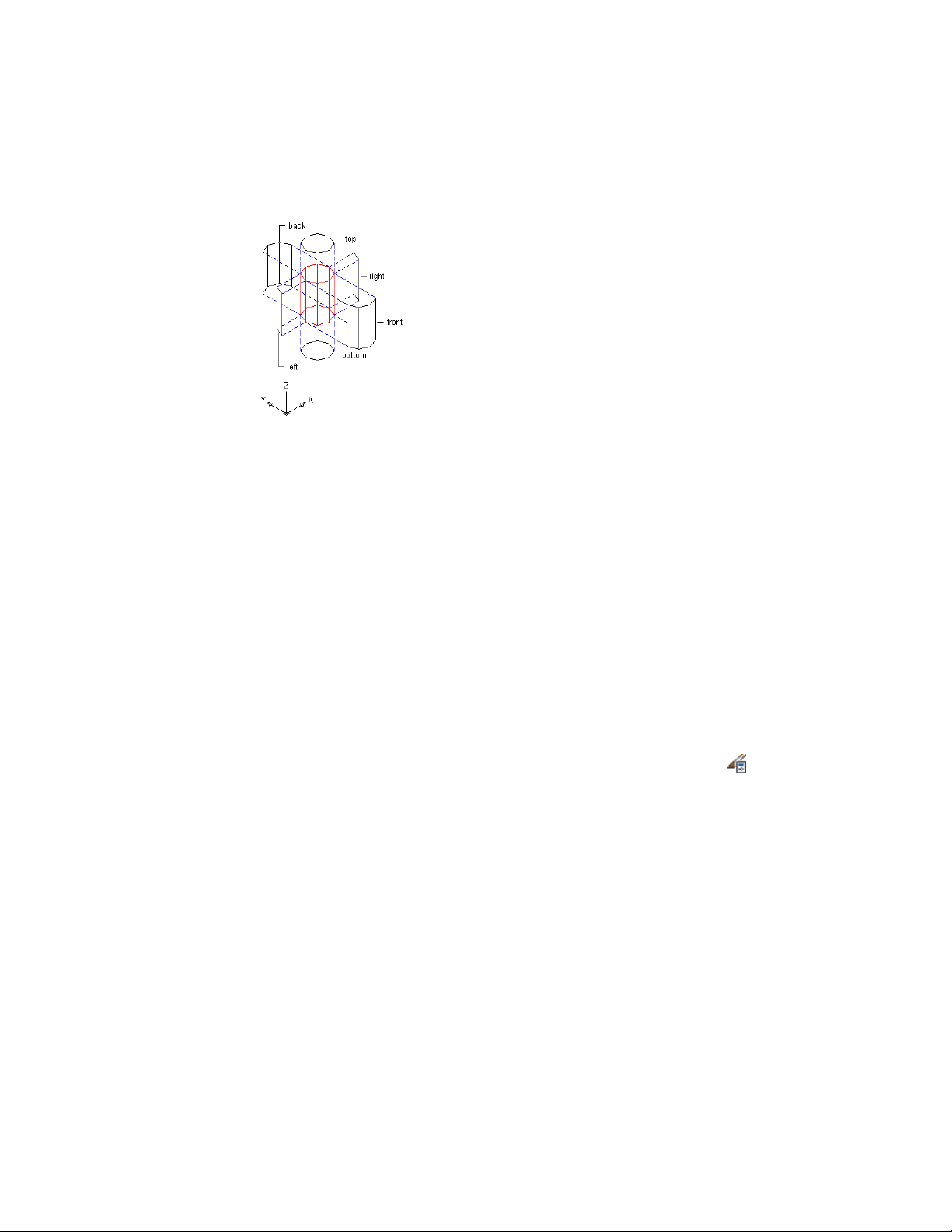
Face assignments from edges extruded in the Z direction
Specifying Faces on Extrusions
Use this procedure to specify the faces on object components created from
extruding a profile. These objects and components include extruded mass
elements, wall body modifiers, custom railing components, and other
components extruded from a profile.
When you create a profile, all the edges are marked for extrusion in the Z
direction. These edge positions are calculated based upon the quadrant in
which the midpoint of the edge lies. You can change the view direction of
edges and the extrusion direction in the profile definition.
Determine the direction of the profile edges before creating objects from the
profile. For example, if you created a profile for a custom railing baluster and
specified the direction of the individual edges, any baluster added to the railing
based on that profile has those assignments. If you later change the edge view
direction in the profile, existing balusters do not change accordingly.
1 Click Manage tab ➤ Style & Display panel ➤ Style Manager .
2 Expand Multi-Purpose Objects, and expand Profiles.
3 Select the profile for the extrusion.
4 Click the Profile Edges tab.
894 | Chapter 13 Materials
Loading ...
Loading ...
Loading ...