Loading ...
Loading ...
Loading ...
the member path, the rigid frame transforms from one shape to several shapes
along its path.
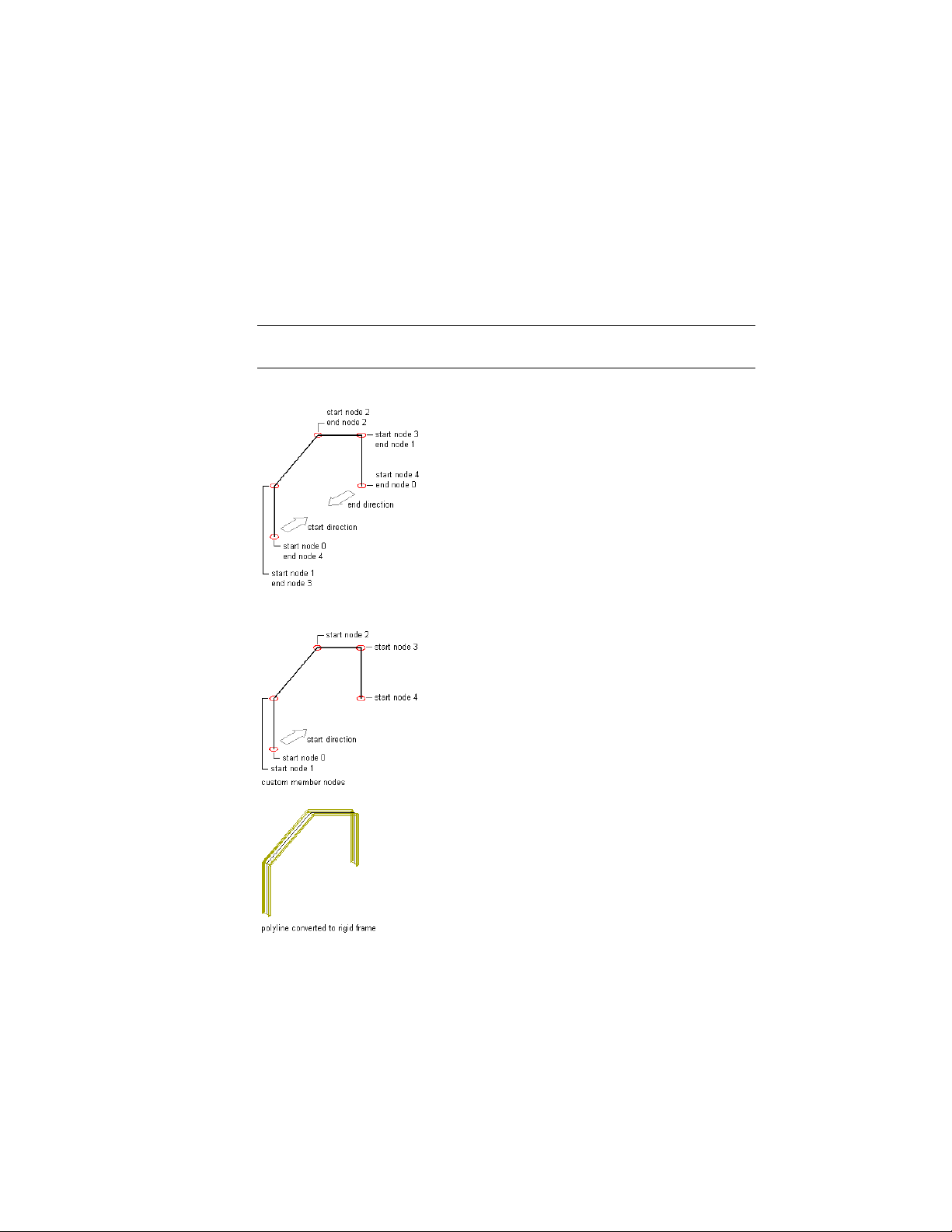
Assign shapes to the rigid frame member relative to the start of the member.
The start point is defined as Node 0. The first vertex of the member is defined
as Node 1, the next vertex is Node 2, and so on until the endpoint of the
member, which is defined as the end node.
NOTE If you assign shapes relative to the end of the member, the endpoint of
the member is defined as Node 0.
Identifying nodes on the member path
Creating the rigid frame
The process of creating this rigid frame has seven steps:
2634 | Chapter 31 Structural Members
Loading ...
Loading ...
Loading ...