Loading ...
Loading ...
Loading ...
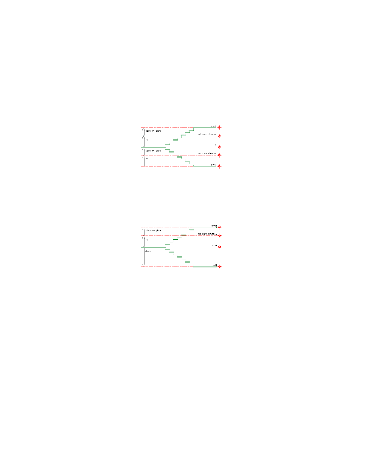
When the Override Display Configuration Cut Plane option is
selected, the cut height elevation is measured from the bottom
of each stair run. The up display components and the above cut
plane display components above the current level are displayed,
and the down display components are not.
Specifying cut plane elevation with display configuration override
When the Override Display Configuration Cut Plane option is
cleared, the cut height elevation is measured from the current
level. The up display components above the current level are
displayed, as are the down display components below the current
level.
Specifying cut plane elevation without display configuration override
6 Make changes to the display of stair components as needed, then
click OK twice.
Specifying Stair Display at Different Levels
1 The following procedure provides an example of how to specify
the display of stair components at different levels in a stair tower.
Create a U-shaped stair, 5’-0” (1520 mm) wide and 12’-0” (3650
mm) high to represent the lobby stairs.
2 Create a second U-shaped stair, 3’-8” (1120 mm) wide and 10’-0”
(3050 mm) high, and locate it 12’-0” (1520 mm) above the lobby
stairs.
Specifying Stair Component Display by Cut Plane Elevation | 2229
Loading ...
Loading ...
Loading ...