Loading ...
Loading ...
Loading ...
independently. For more information, see Specifying the Display of Door and
Window Assemblies on page 1754.
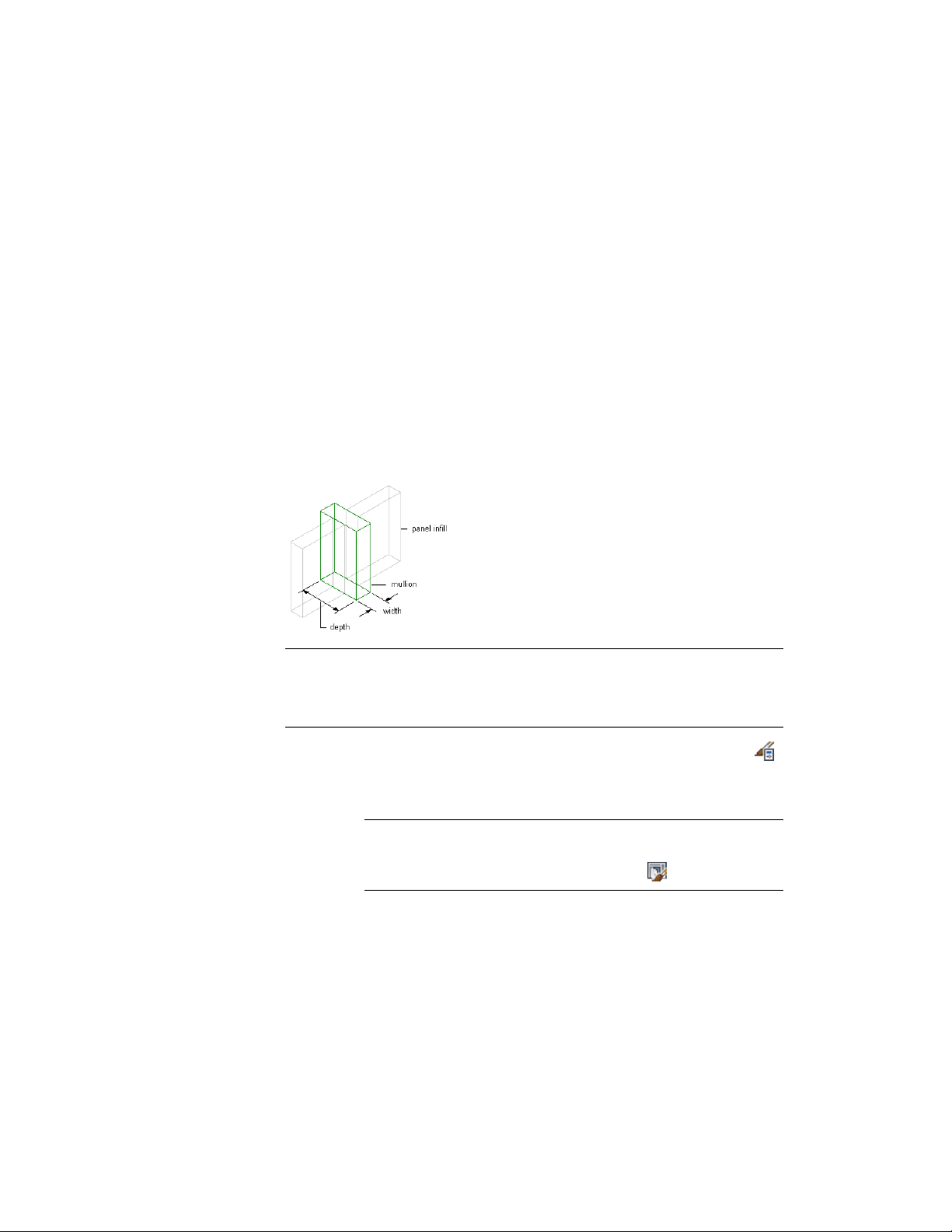
Defining Door and Window Assembly Mullions by Width and
Depth
Use this procedure to define mullions by specifying a width and a depth.
Because door/window assemblies can contain multiple nested grids with
different mullions, it is helpful to use a naming convention for grid mullions
that indicates the grid location or purpose within the door/window assembly.
For example, L3-FL1- Window Mullion identifies a mullion for a window in
a third-level grid on Floor 1.
Specifying Door/Window Assembly mullion width and depth
TIP To remove mullions for butt glazing, create a definition with both width and
depth set to zero. Then assign that definition to the mullions that you want to
remove. For more information, see Removing Mullions from a Door and Window
Assembly Grid on page 1750.
1 Click Manage tab ➤ Style & Display panel ➤ Style Manager .
2 Expand Architectural Objects, and expand Door/Window
Assembly Styles.
NOTE Alternatively, select a door/window assembly in the drawing,
and click Door/Window Assembly tab ➤ General panel ➤ Edit Style
drop-down ➤ Door/Window Assembly Styles .
3 Select a door/window assembly style.
4 Click the Design Rules tab.
5 In the left pane, select Mullions under Element Definitions.
Door and Window Assembly Styles | 1723
Loading ...
Loading ...
Loading ...