Loading ...
Loading ...
Loading ...
Cut Planes and Levels
Levels are represented separately by one or more files and are assembled in a
view or sheet to represent the entire building.
You set the cut plane individually for each level of a building. You create a
drawing file—a construct or a view—that represents the level, and assign a
cut plane to a display configuration within the drawing.
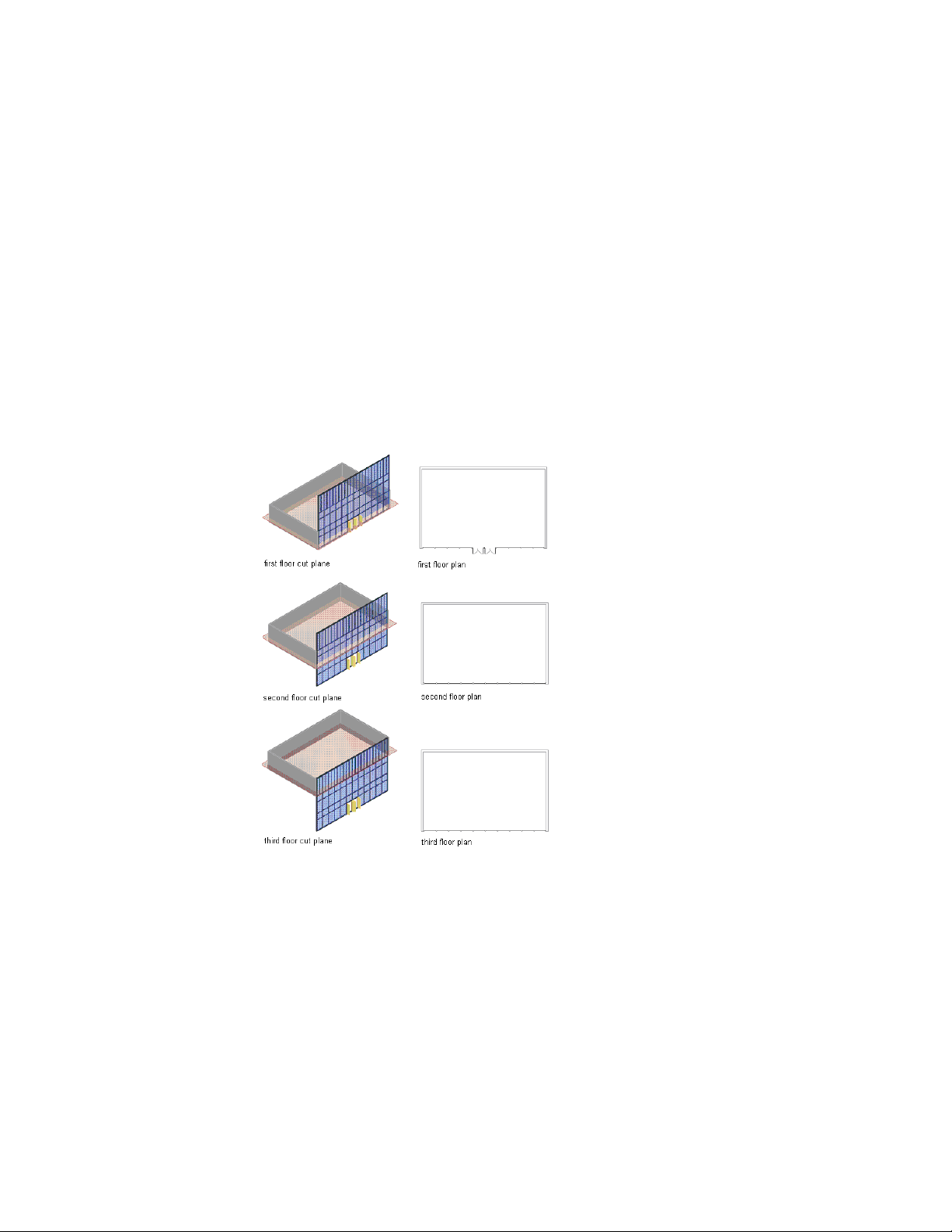
The following images illustrate a curtain wall that spans 3 levels. The images
on the left indicate the cut plane for the associated level drawing. The plans
to the right show how the curtain wall would be displayed in plan view at
each level. Notice the different appearance of the doors and mullions on the
various floor plans.
Specifying 3 cut plane levels
Global Cut Planes
The global cut plane cuts all objects in a drawing at the same height. It is
defined separately for each of the display configurations that can be applied
536 | Chapter 6 Drawing Management
Loading ...
Loading ...
Loading ...