Loading ...
Loading ...
Loading ...
7 If you selected Yes for Override cut plane, enter a value for Height
to define the cut plane for this object.
8 For Cut line angle, enter a value to specify the angle between the
stair cut lines.
9 For Cut line distance, enter a value to specify the distance between
the 2 cut lines.
10 If you selected No for Override cut plane, for Show entire stair
down, specify whether you want to display the stair’ s down display
components (Stringer down, Riser down, Nosing down, and so
on; for more information, see Specifying Stair Component Display
by Cut Plane Elevation on page 2227).
You can also access and modify these same cut plane settings through the
stair’s context menu, as follows:
1 Select the stair you want to change, right-click, and click Edit
Object Display.
2 Click the Display Properties tab.
3 Select the display representation where you want the changes to
appear, and select Object Override.
The display representation in bold is the current display
representation.
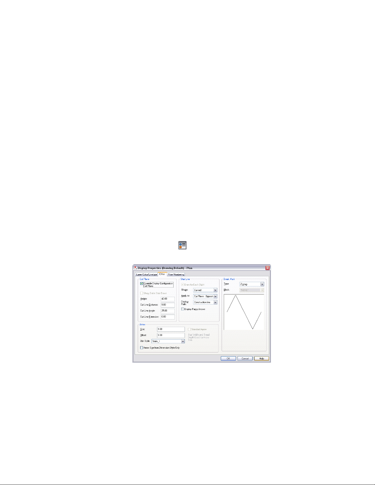
4 If necessary, click .
5 Click the Other tab.
6 In the Cut Plane panel, change the settings as needed.
2240 | Chapter 27 Stairs
Loading ...
Loading ...
Loading ...