Loading ...
Loading ...
Loading ...
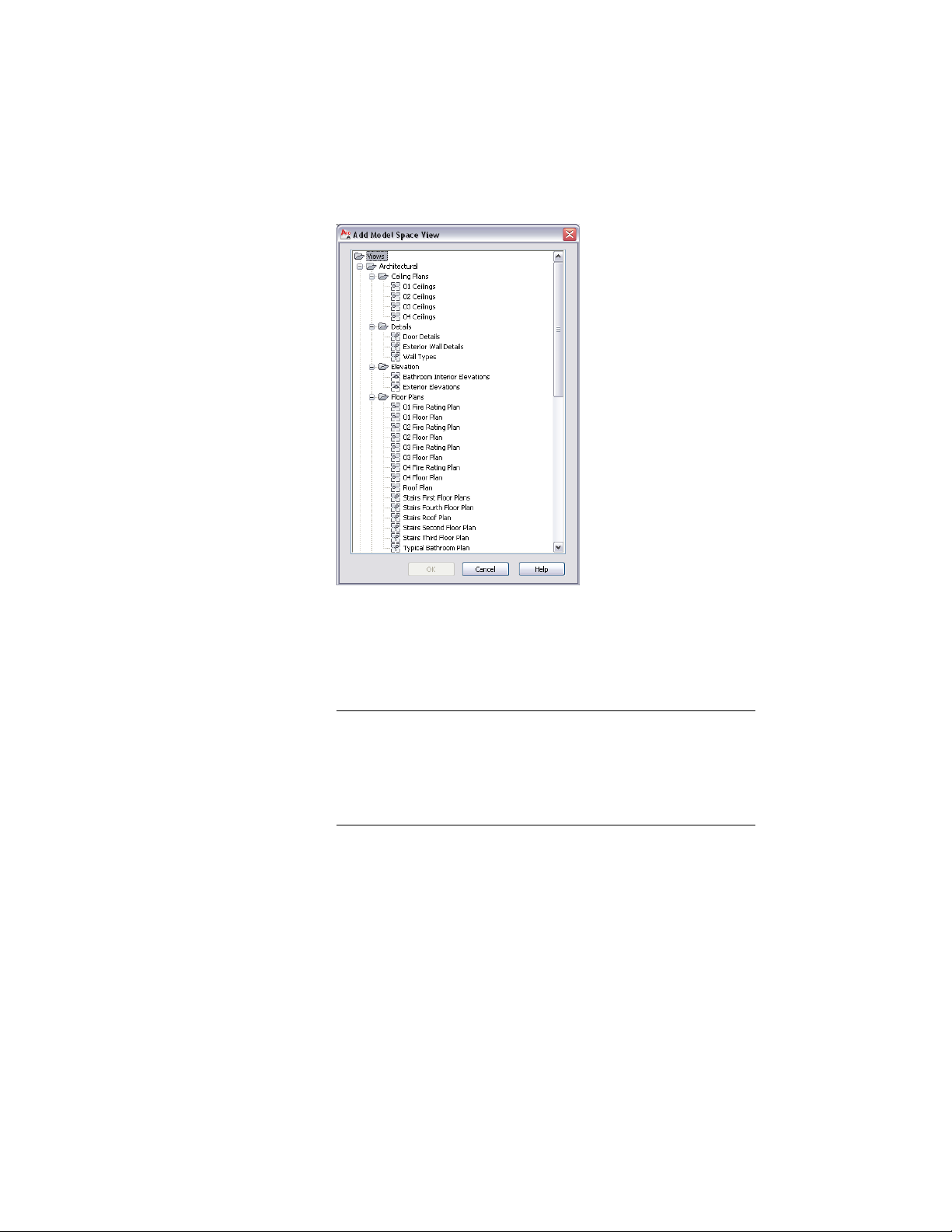
Select a drawing to place the section
15 In the Add Model Space View dialog, select the project view
drawing in which the model space view should be placed, and
click OK.
16 In the drawing area, select the insertion point of the generated
section.
NOTE Although you select the insertion point in the current drawing,
it will be used in the target drawing where the section result is placed.
That way, you have control over the insertion point of the 2D section
without opening the target drawing. You can change the location of
the 2D section later, when you open the drawing in which the 2D
section was placed, and change it there.
Once the model space view has been placed, the field placeholders
in the section callout change to a question mark. To resolve them,
the model space view needs to be placed onto a sheet, as described
in Resolving Fields in Callout Symbols on page 3689.
17 To display the section view in the Project Navigator, navigate to
the target drawing, and expand it.
The model space view is listed under the drawing.
3676 | Chapter 48 Callouts
Loading ...
Loading ...
Loading ...