Loading ...
Loading ...
Loading ...
Or press ENTER to use the line along the X axis as the default
baseline.
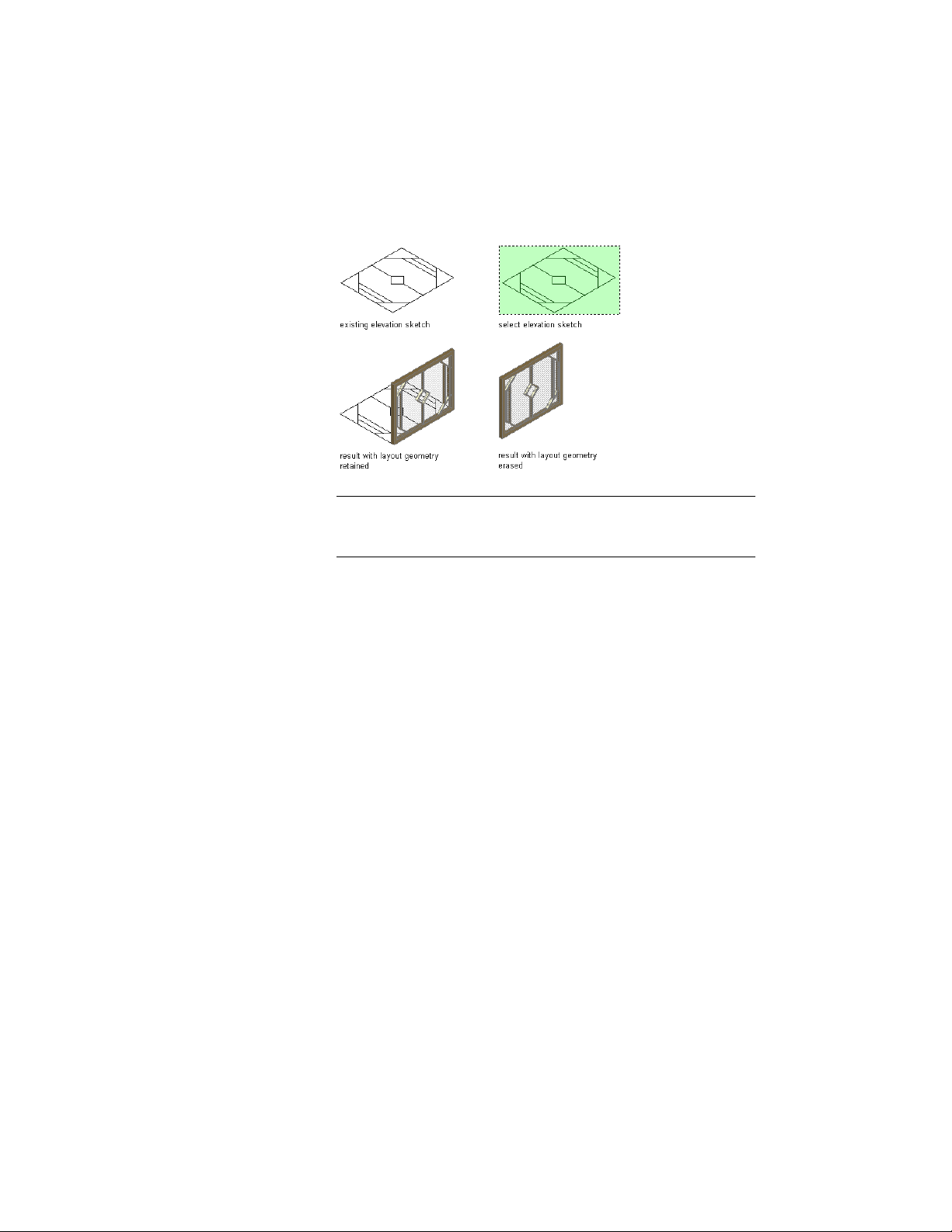
TIP If you draw your linework in the XY plane (in Plan view) and
accept the default baseline, the resulting door/window assembly is
displayed from the Z direction.
6 To erase the lines, enter y (Yes). To have the lines remain after
the door/window assembly is created, enter n (No).
If there is a style applied to the door/window assembly tool, the
new custom style is based on the existing style. The infill, mullion,
and frame definitions are those of the existing style. You can
modify the style without having to create a new one from scratch.
For more information, see Assigning Definitions to Door and
Window Assembly Elements on page 1729.
7 Select the resulting custom door/window assembly, click
Door/Window Assembly tab ➤ Modify panel ➤ Design Rules
drop-down ➤ Save to Style.
8 Click New to create a new door/window assembly style.
9 Enter a name for the new door/window assembly style.
10 Click OK twice.
Creating a Door and Window Assembly Tool
Use this procedure to create a door/window assembly tool and add it to a tool
palette. You may want to create your own door/window assembly tools if you
1684 | Chapter 22 Door and Window Assemblies
Loading ...
Loading ...
Loading ...