Loading ...
Loading ...
Loading ...
Mixed signal option (MSO, R&S MXO5-B1)
R&S
®
MXO 5 Series
385User Manual 1802.3369.02 ─ 02
You can adjust the display of the logic bus signals and the individual digital channels to
optimize the analysis of bus data:
●
Show the digital channels which are assigned to the bus, drag them to the optimal
position, and scale them.
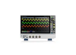
●
Adjust size and position of the logic signal: Therefore, tap the Lx signal or the sig-
nal icon, and use the [Position] and [Scale] knobs.
●
Adjust size and position of all active digital channels: Therefore, tap one of the Dx
signals, and use the [Position] and [Scale] knobs.
●
Show the result table of the decoded clocked bus signal.
Remote commands:
●
PBUS<pb>:DIGSignals:POSition on page 754
●
PBUS<pb>:DIGSignals:SCALe on page 755
●
PBUS<pb>:POSition on page 756
●
PBUS<pb>:SCALe on page 756
To access and analyze one or more specific acquisitions, you can use the "History" in
the common way.
Furthermore, you can zoom in digital signals and bus signal in the same way as in ana-
log waveforms.
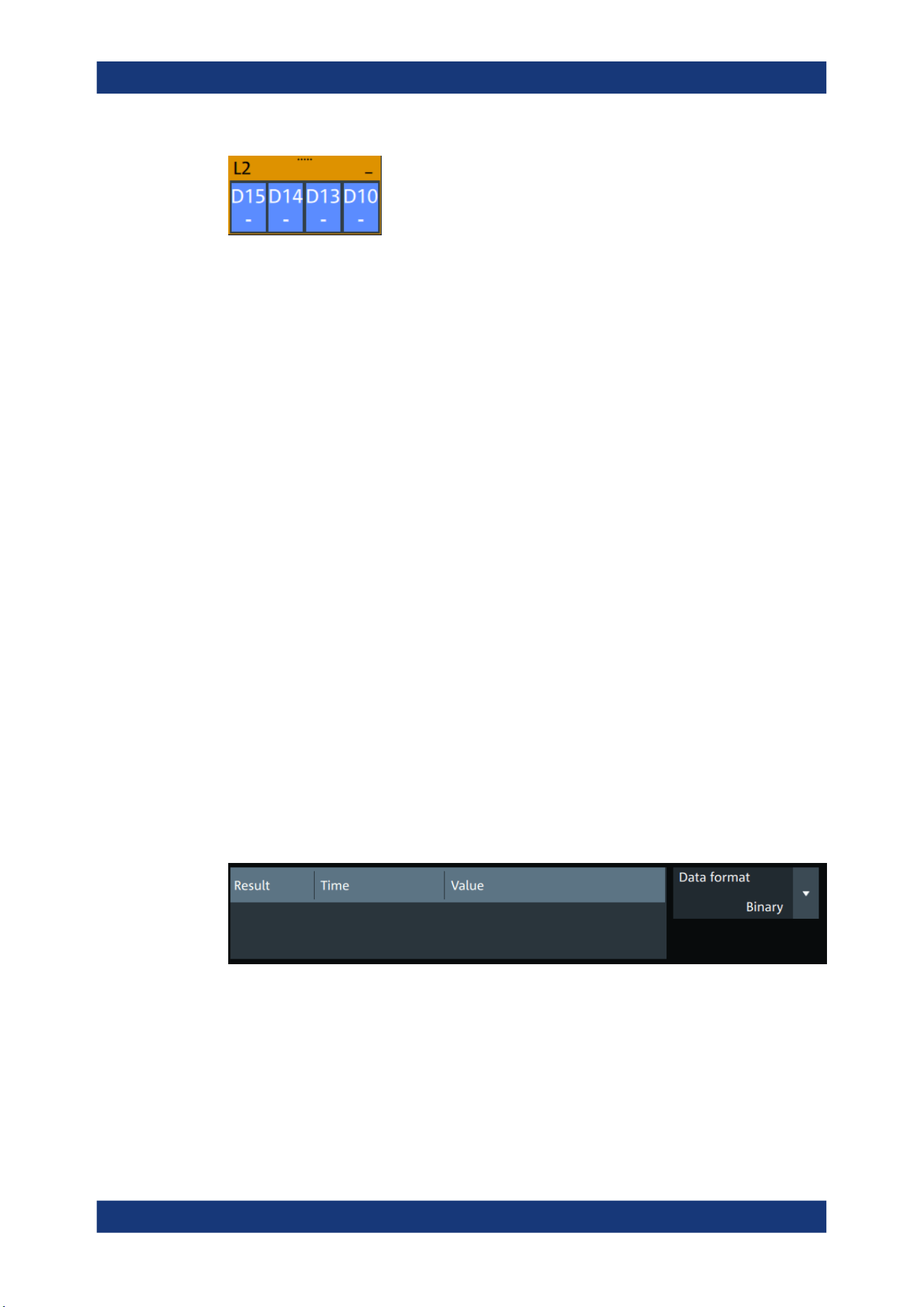
14.2.1 Logic bus - decode table
Decoding is available for clocked buses.
The decode table shows the decoded data words of the bus signal and the corre-
sponding time. Each clock edge corresponds to one row in the table. Beside the table,
you can select the data format of the bus values.
The results can be saved to a .csv or .html file.
Display
Loading ...
Loading ...
Loading ...