Loading ...
Loading ...
Loading ...
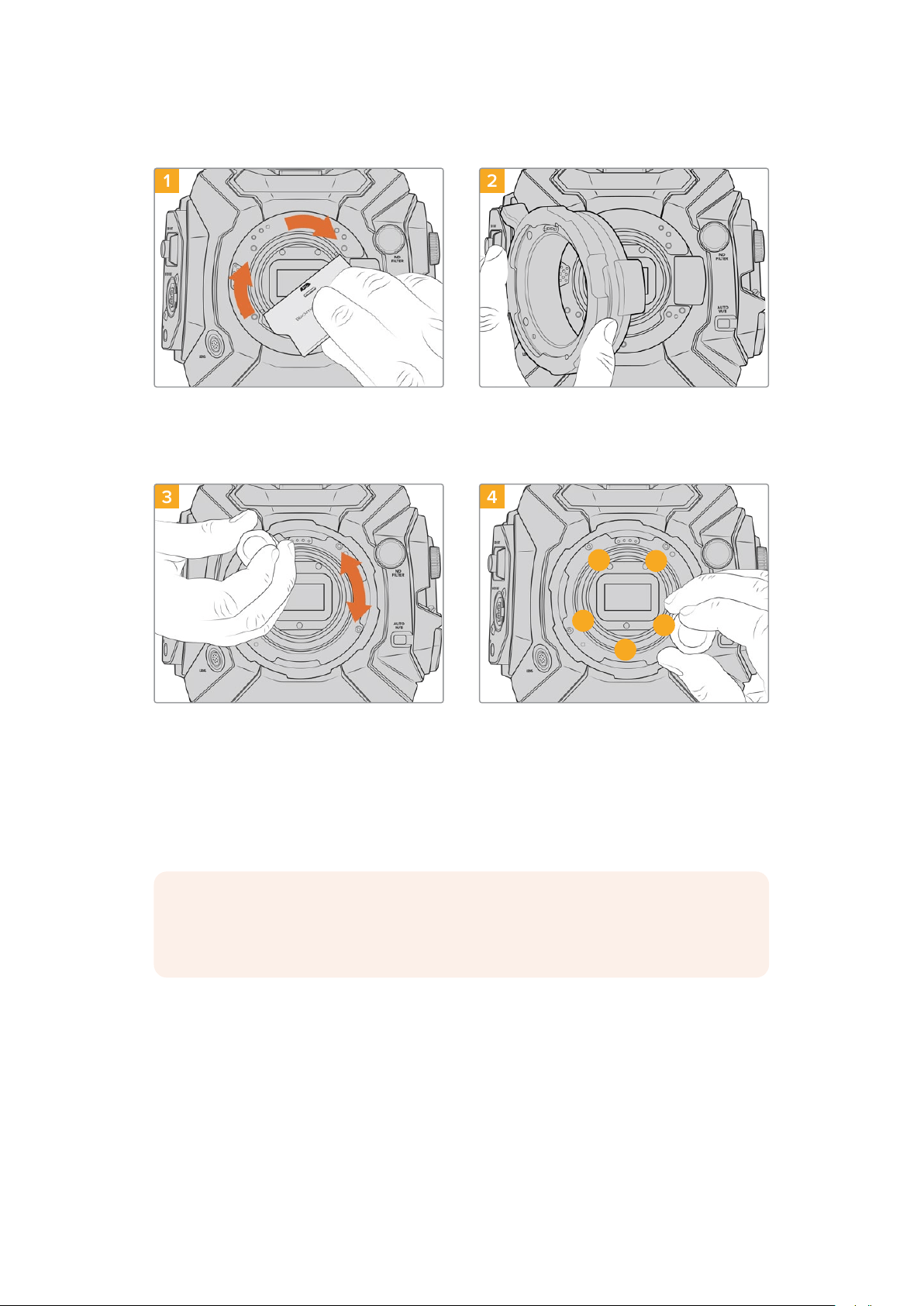
Attaching the PL Mount
1 2
Gently insert the PL baffle into the center of the lens
mount and turn until it is finger tight. Use the wide
end of the baffle tool to tighten the baffle slightly.
You need just enough pressure to keep it in place.
Ensurethe pins on the PL mount for
Cooke/iTechnology are located at the
12o’clockposition.
3 4
1
3
4
5
2
Loosely turn the five mounting screws until initial
contact is made with the shoulder of the lens
mount. To access all five screws, you will need to
rotate the PL locking ring, as some holes are
obscured when the ring is either open or closed.
Using the 2mm Hex driver, or torque wrench with
2mm Hex key, apply one full turn of pressure to
mounting screw 1, followed by one full turn to
screw2. Repeat for screws 3and 4, then 5.
Continue to apply one full turn to each screw in
the sequence above until all screws have reached
the maximum torque of 0.45Nm.
NOTE When removing the PL mount, simply follow the instructions in reverse order
from step 4 to step 1. Don’t forget to remove the PL baffle and store it securely with the
PL mount.
To attach a PL mount lens:
1 Open your camera’s PL locking ring by rotating it counterclockwise until it stops.
2 Align one of the lens’ four flange notches with the locating pin on the camera mount.
Be sure to align the lens for easy viewing of the lens marks.
3 Tighten the PL locking ring by rotating it clockwise. If attaching a PL lens with a servo
unit to URSA Broadcast G2, you can also connect the 12 pin broadcast connector for
servo control.
197Interchangeable Lens Mount
Loading ...
Loading ...
Loading ...