Loading ...
Loading ...
Loading ...
Operating the instrument
R&S
®
MXO 4 Series
47User Manual 1335.5337.02 ─ 05
Diagram
A diagram shows one or more waveforms: channel, reference, and math waveforms.
Zoom details, spectrum and other special waveforms are shown in separate diagrams.
To arrange the diagrams on the screen, the Rohde & Schwarz SmartGrid function
helps you to find the target place simply and quickly. For details, see Chapter 4.5,
"Rohde & Schwarz SmartGrid", on page 53. You can also adjust the diagram size by
dragging the diagram border.
Layout
A layout shows a set of diagrams and result tables. You can configure up to four lay-
outs using the SmartGrid functionality. For details, see Chapter 4.5, "Rohde & Schwarz
SmartGrid", on page 53.
Grid
The grid shows the vertical and horizontal divisions. The division lines are labeled with
the correspondent values. The grid labels have the color of the waveform to which they
belong. If several waveforms are shown in one diagram, the grid has the color of the
selected waveform.
Trigger position and trigger level
The blue markers show the horizontal position of the trigger and the vertical trigger
level. You can touch and move the trigger markers in the diagram to set the positions.
The trigger point is the zero point of the diagram.
The trigger position can be moved outside the diagram.
Trigger, Horizontal, Acquisition
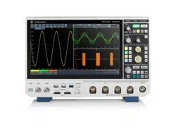
The "Trigger", "Horizontal" and "Acquisition" labels show the main timebase and trigger
settings. If you tap a label, the relevant dialog box opens.
Figure 4-2: Trigger label on the toolbar
1 = Trigger source
2 = Trigger type
3 = Trigger level
4 = Trigger mode
5 = Trigger state
6 = Trigger type specific settings
7 = Trigger slope
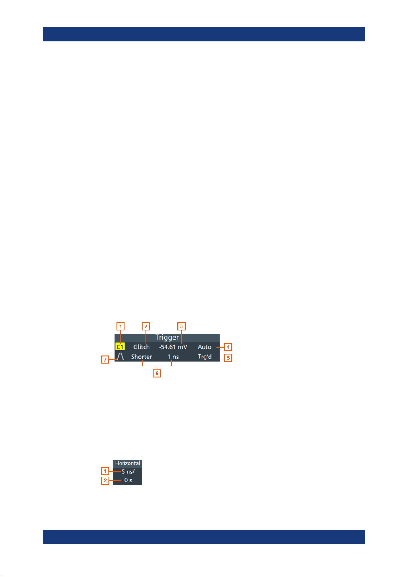
Figure 4-3: Horizontal label on the toolbar
Touchscreen display
Loading ...
Loading ...
Loading ...