Loading ...
Loading ...
Loading ...
3 Function diagrams
3.16 Signals and monitoring functions
SINAMICS G120C
440 List Manual (LH13), 04/2014, A5E33840768B AA
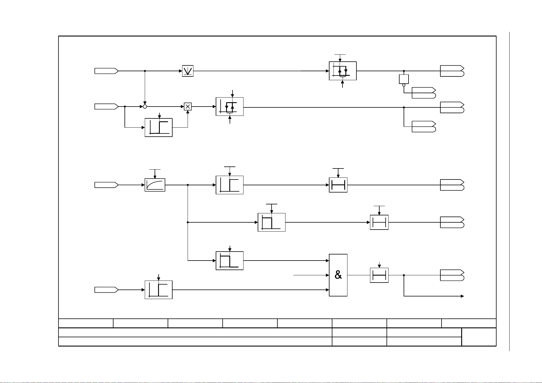
Fig. 3-104 8020 – Monitoring functions 1
- 8020 -
Function diagram
87654321
fp_8020_97_05.vsd
Signals and monitoring functions
SINAMICS G120C
07.04.2014 V4.7
Monitoring functions 1
0
1
[8010.2]
+
–
[3050.8]
[6714.8]
[6730.4]
[6731.4]
0
1
0
T0
1
0
0
0
1
n_min
p1080
ZSW monitor 1
r2197
r2197
r2169
n_act smth message [rpm]
r1119
RFG setp at inp [rpm]
r0068
I_act abs val [Arms]
r0072
U_output [Vrms]
[2511.6]
[2511.6]
ZSW monitor 1
r2197
r2197
Enable Pulses
1 = |n_act| <= n_min p1080
1 = |n_act| >= n_set
1 = Output load is not
present
Drive: No motor detected
A07929
-1
1
0
[0]
2.00 [1/min]
Hysteresis speed 3
2.00 [1/min]
Hysteresis speed 3
2000 ms
<1> Calculated.
<1>
<1>
1
.0
[2534.2]
[2534.2]
[2534.2]
r2197.4
r2197
r0053.2
r0053
r0053.6
r0053
M_act_filt T
0 ... 1000000 [ms]
p3233 [D] (100)
I_thres
p2170
I_thresh rch t_del
p2171
1
0
0T
0
1
I_thres
p2170
I_thresh rch t_del
p2171
0T
ZSW monitor 2
r2198
r2198
ZSW monitor 1
r2197
r2197
1 = I_act >=
I_threshold value p2170
1 = |I_act| <
I_threshold value p2170
.8
.8
.11
[2534.2]
[2536.2]
p0305 • 3%
Loading ...
Loading ...
Loading ...