Loading ...
Loading ...
Loading ...
3 Function diagrams
3.13 Vector control
SINAMICS G120C
406 List Manual (LH13), 04/2014, A5E33840768B AA
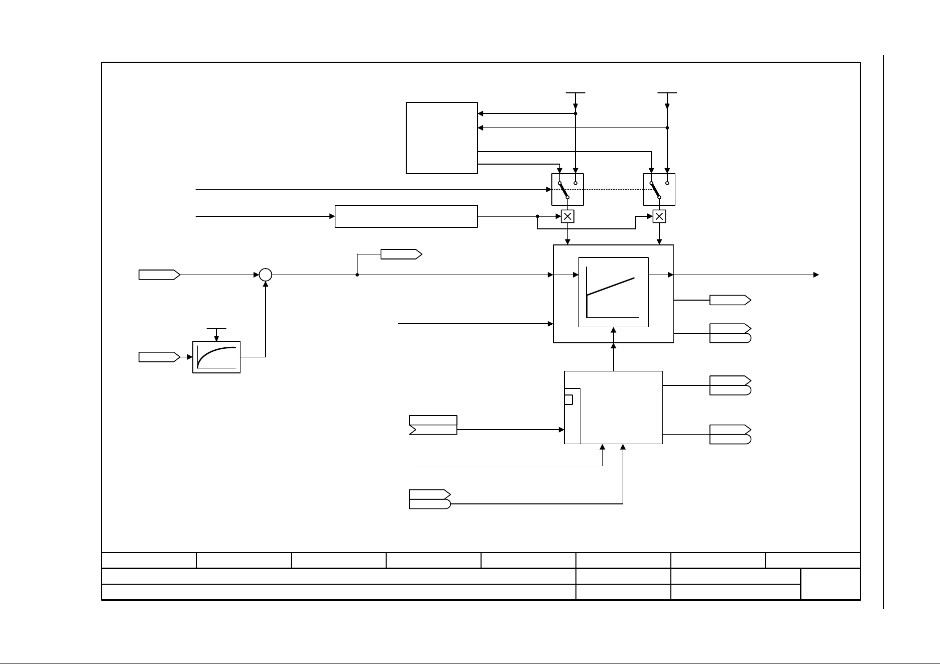
Fig. 3-73 6040 – Speed controller
ZSW n_ctrl
r1407
r1407
- 6040 -
Function diagram
87654321
fp_6040_97_05.vsd
Vector control
SINAMICS G120C
07.04.2014 V4.7
Speed controller
[6030.8]
+
-
[6060.1]
[6030.1]
Kp_n_basic
Tn_n_basic
Tn_n_adapt
1 01 0
Kp_n_adapt
[2522.7]
[2522.3]
[2522.3]
Kp
<1>
Tn
[2522.3]
<1>
1 = Kp/Tn adaptation active
1 = Automatic Kp/Tn adaptation active
Dynamic reduction, field weakening
r0064
n_ctrl system dev [rpm]
r1438
n_ctrl n_set [rpm]
r0063
n_act [rpm]
n_C n_act T_s SL
0.00 ... 32000.00 [ms]
p1452 [D] (10.00)
Enable speed controller
from sequence control: Operation
.7
For p1472 = 0.0 s or 100.0 s, the I component is
inhibited (integral action time = infinite).
1 = Torque limit reached
Integrator control
Speed controller
n_ctrl SL Kp
0.000 ... 999999.000
p1470 [D] (0.300)
M_set from speed controller
1 = Speed controller active
ZSW n_ctrl
r1407
r1407
.5
1 = Speed controller, I component set
ZSW n_ctrl
r1407
r1407
.6
ZSW n_ctrl
r1407
r1407
.3
r1482
n_ctrl I-M_outp [Nm]
n_ctrl SL Tn
0.0 ... 100000.0 [ms]
p1472 [D] (20.0)
[6721.8]
Torque setting value, speed controller
n_ctrl M_sv MHB
(0)
p1475 [C]
Kp_n/Tn_n
adaptation
Kp Tn
1 = Speed controller, I component held
Loading ...
Loading ...
Loading ...