Loading ...
Loading ...
Loading ...
SINAMICS G120C
List Manual (LH13), 04/2014, A5E33840768B AA
423
3 Function diagrams
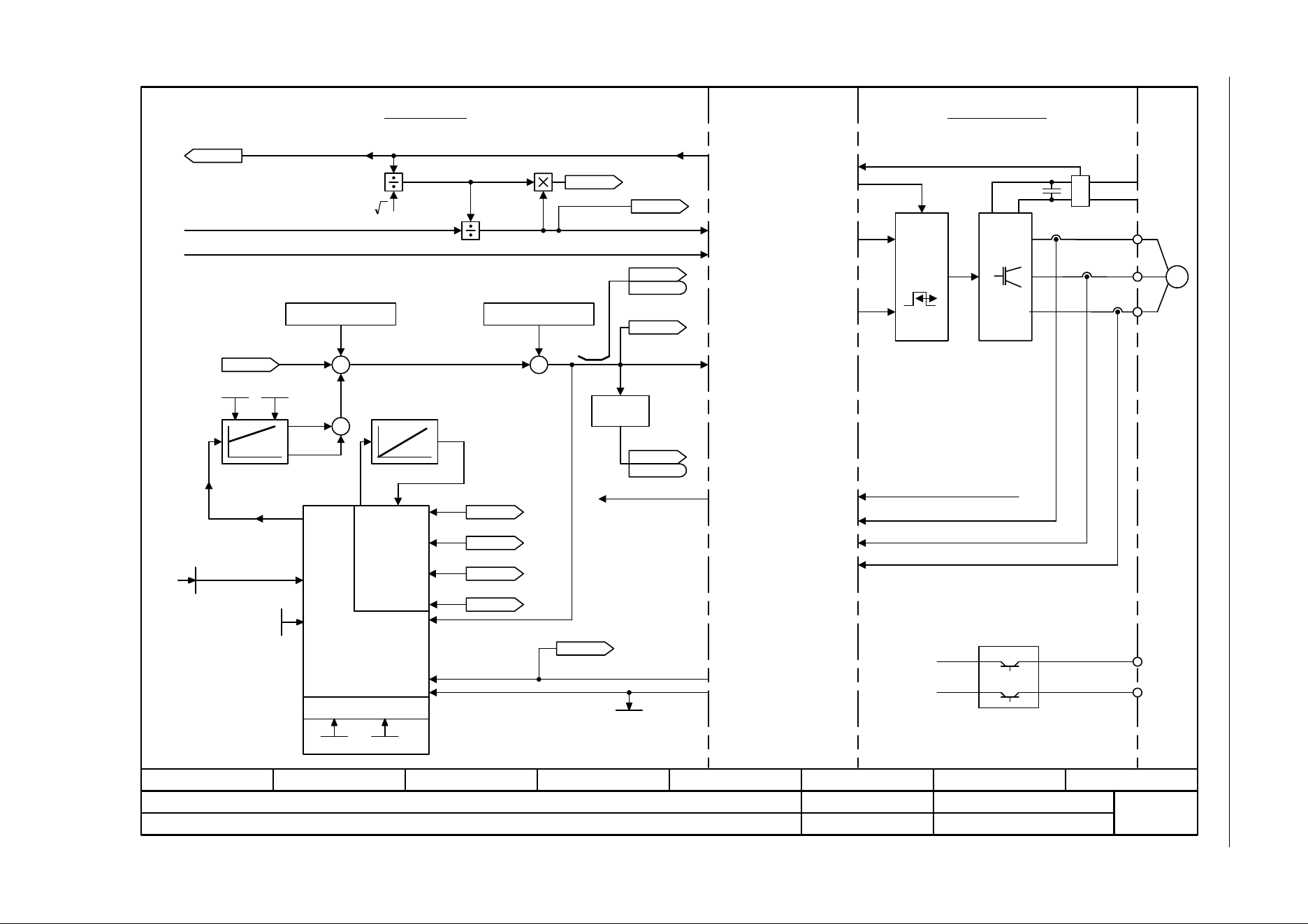
3.13 Vector control
Fig. 3-90 6731 – Interface to the Power Module (PEM, p0300 = 2)
- 6731 -
Function diagram
87654321
fp_6731_97_05.vsd
Vector control
SINAMICS G120C
07.04.2014 V4.7
Interface to the Power Module (PEM, p0300 = 2)
PWM
M
~
U
V
W
+ BRP
-BRN
P24
M
2
I_max Power Module
[6640.1]
[6310.1]
[6799.1]
[6714.8]
[6714.8]
[6799.1]
[6799.1]
[6724.1]
[6799.1]
p1764 p1767
+
[2526.2]
Pre-control speed
Brake control
I_max PM
Pulse enable HW
DC link voltage
Power ModuleControl Unit
U_set
U_angle
Motor model
Model control
kT estimator
p0316
p0357
p1780.3
PEM: Permanent-magnet synchronous motor
r0070
Vdc act val [V]
r0072
U_output [Vrms]
r0074
Modulat_depth [%]
ZSW cl-loop ctrl
r0056
r0056
.11
r0066
f_outp [Hz]
ZSW cl-loop ctrl
r0056
r0056
U_phase act val
r0089
r1733
Quad U set [Vrms]
r0077
Iq_set [Arms]
r0076
Id_act [Arms]
R_stator act [Ohm]
r0395 [D]
Vibration damping
Sign
+ or -
Current model
[6030.8]
p1755
Outp_ph_seq rev
p1820
r0063
n_act [rpm]
[0]
r1732
Direct U set [Vrms]
[0]
r0069[0..6]
I_phase act value [A]
Internal interface Power Module - Control Unit
+
+
+
.7
[6714.1]
[6714.6]
[6714.6]
p1756
[2701.8]
Loading ...
Loading ...
Loading ...