Loading ...
Loading ...
Loading ...
3 Function diagrams
3.8 Internal control/status words
SINAMICS G120C
374 List Manual (LH13), 04/2014, A5E33840768B AA
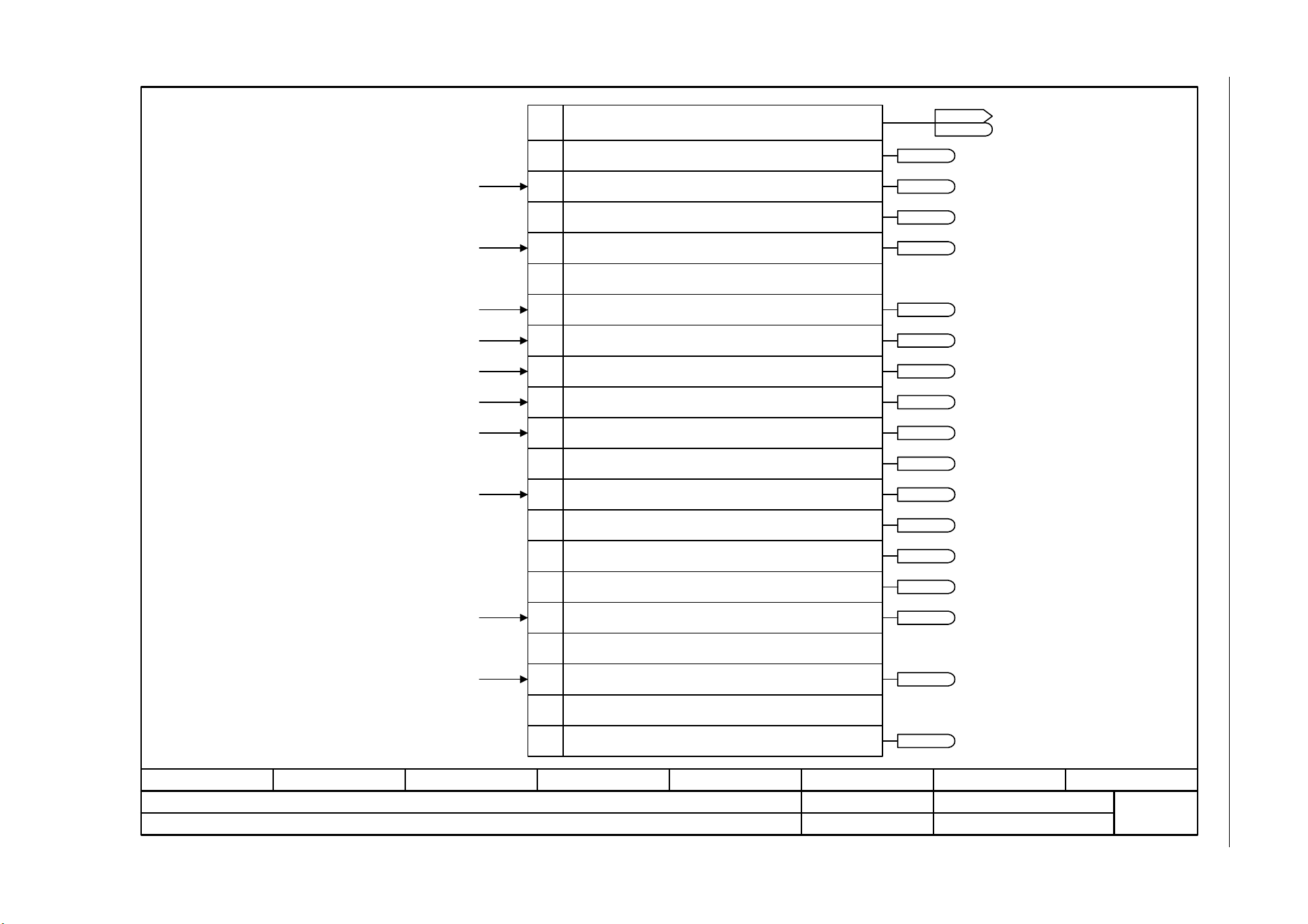
Fig. 3-46 2522 – Status word, speed controller
- 2522 -
Function diagram
87654321
fp_2522_97_05.vsd
Internal control/status words
SINAMICS G120C
07.04.2014 V4.7
Status word, speed controller (r1407)
1
2
3
4
5
6
7
8
9
10
11
0
12
13
14
15
r1407.8
r1407.9
r1407.11
r1407.1
r1407.7
r1407.10
r1407.11
r1407.5
r1407.6
r1407.3
r1407.12
r1407.13
r1407.0
From the changeover, closed-loop control types
From the control unit
Status word speed controller (r1407)
Bit No.
1 = U/f control active
1 = Sensorless operation active
1 = Closed-loop speed control active
1 = Speed controller, I component held
1 = Speed controller, I component set
1 = Torque limit reached
1 = Torque limiting, upper, active
1 = Torque limiting, lower, active
1 = Droop enabled
1 = Speed setpoint limited
1 = Ramp-function generator set
1 = Sensorless operation due to a fault
1 = I/f control active
1 = Torque limit reached (without pre-control)
Ramp-function generator tracking [1550.7]
Speed controller [6040.4]
Motor locked/stalled [8012.5]
From the speed setpoint [6030.3]
From the torque setpoint [6060.4], [6060.7]
From the torque setpoint [6060.5]
From the speed controller [6040.7]
From the speed controller [6040.7]
ZSW n_ctrl
r1407
r1407
Reserved
From the torque setpoint [6060.5]
0 = Torque control active
16
17
Reserved
1 = Speed limiting control active
From the speed limiting [6640.8]
r1407.17
r1407.15
r1407.14
From the torque setpoint [6060.5]
r1407.2
...
23
Reserved
1 = Acceleration model switched on
r1407.23
Loading ...
Loading ...
Loading ...