Loading ...
Loading ...
Loading ...
3 Function diagrams
3.13 Vector control
SINAMICS G120C
418 List Manual (LH13), 04/2014, A5E33840768B AA
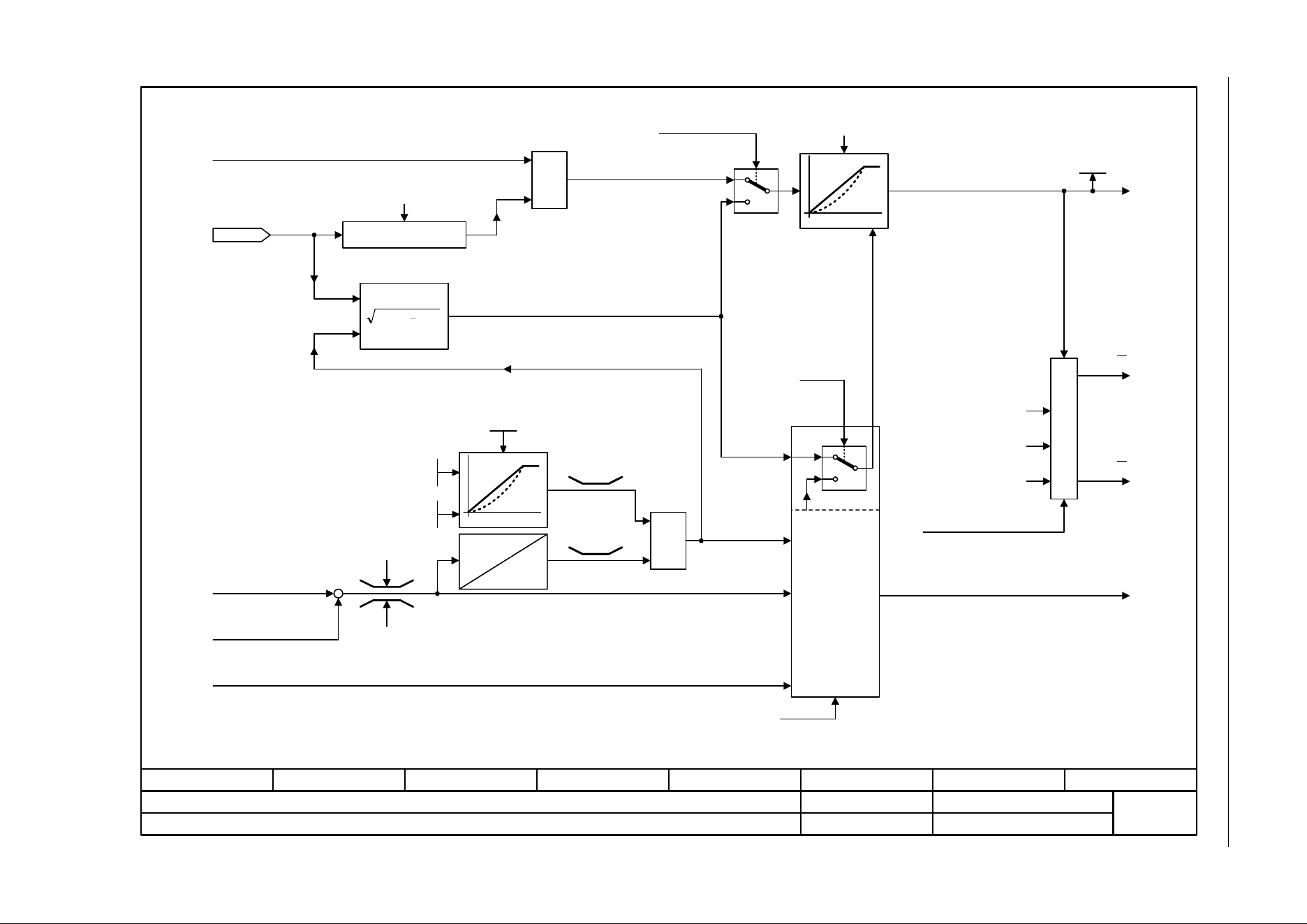
Fig. 3-85 6721 – Id setpoint (PEM, p0300 = 2)
- 6721 -
Function diagram
87654321
fp_6721_97_05.vsd
Vector control
SINAMICS G120C
07.04.2014 V4.7
Id setpoint (PEM, p0300 = 2)
1
0
[6060.7]
[6714]
MAX
MIN
22
Iq
Iabs
[6724]
M
Iq
[6640.5]
[6710.2]
[6799.7]
[6714]
Ld
Lq
kt
Rel
[6731.2]
[6040.4]
[6731.3]
[6060.4]
r1538
r1539
n-Ctrl = 1
Iabs
pre
M
1
0
Iabs
(r1407.2)
0 = M-Ctrl
1 = n-Ctrl
I
d
Id_inject
Iq
M
From Id_field weakening
r1515 M_suppl total
M_acceleration
Motor model deviation component 1
Load angle correction
from the model
control
M adaptation
To current controller
kT adaptation corrective value
from model control
Torque setting value, speed controller
Id_set
Mot t_excitation
0.000 ... 20.000 [s]
p0346 [D] (0.000)
Id_setp total [Arms]
r1624
PEM: Permanent-magnet synchronous motor
Load angle for
synchronous motors
90°
r0077
Iq_set [Arms]
40 [ms]
Motor reluctance torque
constant
Motor leakage inductance,
total
Motor stator inductance,
d axis
M_set static
-200.0 ... 200.0 [%]
p1610 [D] (50.0)
M_suppl_accel
0.0 ... 200.0 [%]
p1611 [D] (30.0)
0.9 x
r0067
r0067
Loading ...
Loading ...
Loading ...