Loading ...
Loading ...
Loading ...
3 Function diagrams
3.2 Explanation of the function diagrams
SINAMICS G120C
324 List Manual (LH13), 04/2014, A5E33840768B AA
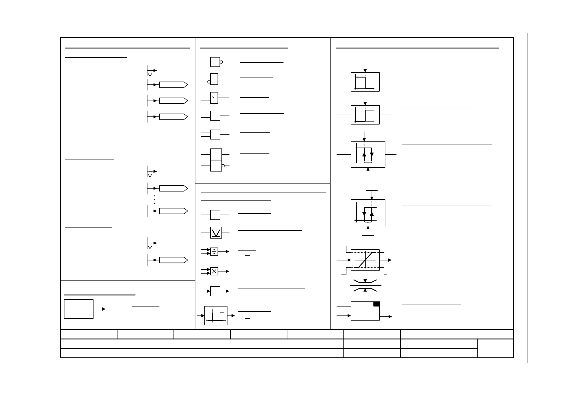
Fig. 3-2 1021 – Explanation of the symbols (part 2)
- 1021 -
Function diagram
87654321
fp_1021_97_61.vsd
Explanations on the function diagrams
SINAMICS G120C
07.04.2014 V4.7
Explanation of the symbols (part 2)
y = -x
y = |x|
y =
1
&
x
y
xy
>0
-1
xy
x
2
x
1
y
S Q
R Q
S
y
x
1
0
0
1
y
x
S
y =
LU
LL MLL
MLU
xy
SET
S & H
xyx
y
0
1
S
H
y
x
0
1
H
S
yx
Symbols for logic functions
Logical inversion
AND element
R/S flip-flop
S = setting input
R = reset input
Q = non-inverted output
Q = inverted output
Symbols for computational and closed-loop control
functions
Threshold value switch 1/0
Outputs at y a logical "1" if x < S.
Threshold value switch 0/1
Outputs at y a logical "1" if x > S.
Threshold value 1/0 with hysteresis
Outputs a logical "1" at y if x < S.
If x >= S + H then y returns to 0.
Threshold value 0/1 with hysteresis
Outputs a logical "1" at y if x > S.
If x <= S - H then y returns to 0.
Limiter
x is limited to the upper limit LU and the lower limit LL
and output at y.
The digital signals MLU and MLL have the value "1", if
the upper or lower limit is active.
Sample & Hold element
Sample and hold element.
y = x if SET = 1
(not retentively saved at POWER OFF)
Symbols for computational and closed-
loop control functions
Sign reversal
Absolute value generator
Divider
Comparator greater than 0
y = 1, if the analog signal x > 0, i.e. is
positive.
Differentiator
Symbol for monitoring
Monitoring
Monitoring
Axxxxx
or
Fxxxxx
OR element
Exclusiv-OR/XOR
y = 1 when x1 x2 is.
or
x
1
x
2
1
=1
x
1
y
x
2
dx
dt
p2900[D]
p2901[D]
-10 000.00...10 000.00 [%]
p2900[D] (0.00)
-10 000.00...10 000.00 [%]
p2901[D] (0.00)
-210 000.000...210 000.000 [1/min]
p1001[D] (0.000)
p1001[D]
-210 000.000...210 000.000 [1/min]
p1015[D] (0.000)
p1015[D]
-100 000.00...100 000.00 [Nm]
p2930[D] (0.00)
p2930[D]
r2902[0...14]
[%]
p2902[0...14] (0.00)
p2902[0] = +0 %
p2902[1] = +5 %
p2902[2] = +10 %
p2902[3] = +20 %
p2902[4] = +50 %
p2902[5] = +100 %
p2902[6] = +150 %
p2902[7] = +200 %
p2902[8] = -5 %
p2902[9] = -10 %
p2902[10] = -20 %
p2902[11] = -50 %
p2902[12] = -100 %
p2902[13] = -150 %
p2902[14] = -200 %
d
dt
Pre-assigned connectors and binectors
Fixed speed values
Fixed torque value
n_set_fixed 1
-210000.000 ... 210000.000 [rpm]
p1001 [D] (0.000)
Fixed value 1 [%]
-10000.00 ... 10000.00 [%]
p2900 [D] (0.00)
Fixed value M [Nm]
-100000.00 ... 100000.00 [Nm]
p2930 [D] (0.00)
or
or
Fixed percentage values
or
Fixed value
2 [%]
Fixed value 1 [%]
n_set_fixed 1
n_set_fixed 15
Fixed value
M [Nm]
y = x
1
•x
2
x
2
x
1
y
Multiplier
Comparator
=
x
1
y
x
2
y = 1 when x1 = x2 is.
with logical inversion of an input signal
Fixed values
In the bottom right-hand
corner of the diagram.
Loading ...
Loading ...
Loading ...