Loading ...
Loading ...
Loading ...
3 Function diagrams
3.2 Explanation of the function diagrams
SINAMICS G120C
326 List Manual (LH13), 04/2014, A5E33840768B AA
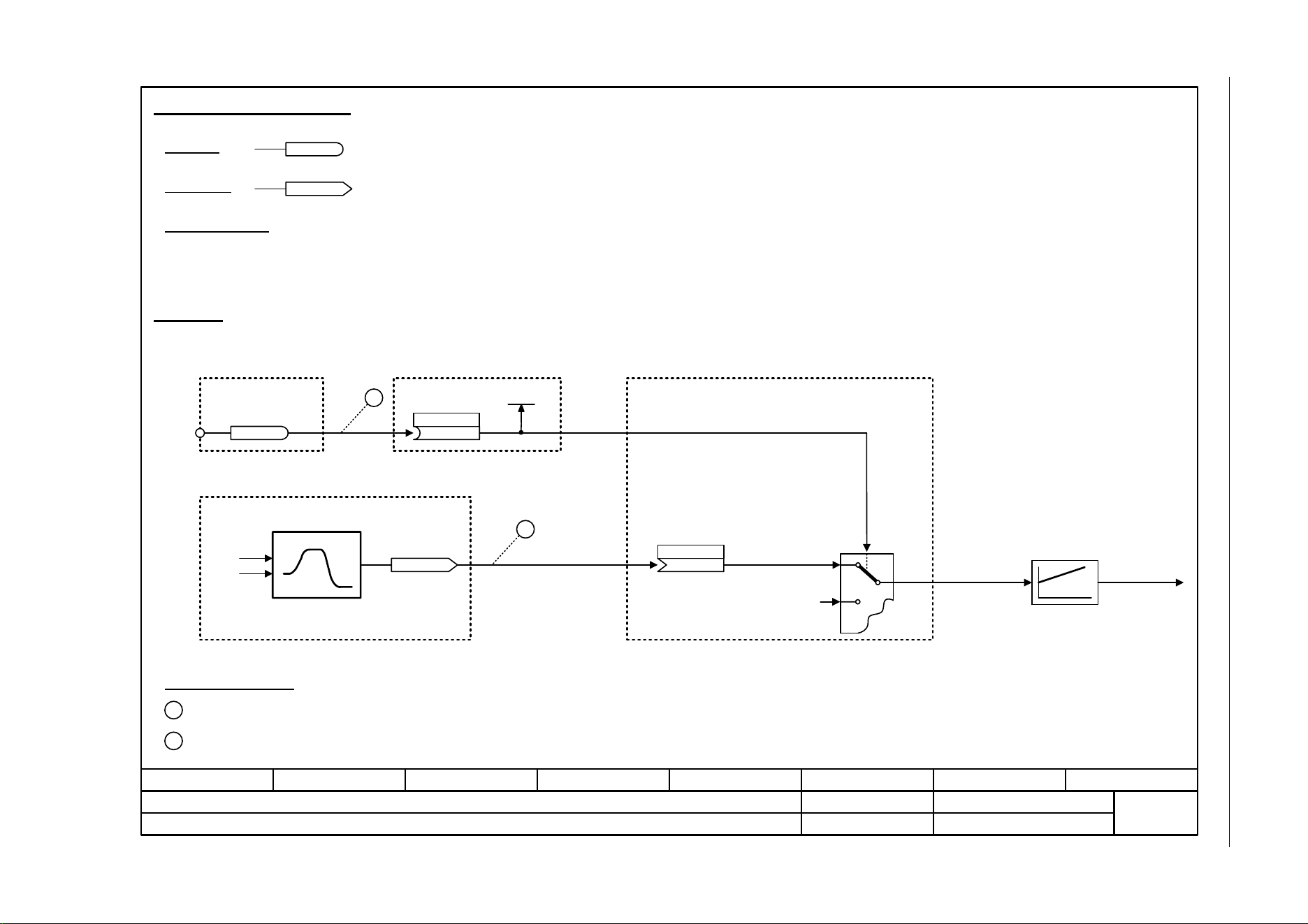
Fig. 3-4 1030 – Handling BICO technology
- 1030 -
Function diagram
87654321
fp_1030_97_61.vsd
Explanations on the function diagrams
SINAMICS G120C
07.04.2014 V4.7
Handling BICO technology
r0723.15
r0723
r0722.0
1
2
722.0
p1055[C]
Kl. 5
r0967.8
[2220] [2501]
[3020]
r1050
[3030]
2
1
p1055[0] = 722.0
p1070[0] = 1050
Main setpoint
(755[0])
p1070[C]
Handling BICO technology
Binector:
Connector:
Raise
Connectors are "analog signals" that can be freely interconnected (e.g. percentage variables, speeds or torques).
Connectors are also "CO:" display parameters (CO = Connector Output).
Parameterization:
At the signal destination, the required binector or connector is selected using appropriate parameters:
"BI:" parameter for binectors (BI = Binector Input)
or
"CI:" parameter for connectors (CI = Connector Input)
Example:
The main setpoint for the speed controller (CI: p1070) should be received from the output of the motorized potentiometer
(CO: r1050) and the "jog" command (BI: p1055) from Digital Input DI 0 (BO: r0722.0, Terminal 5 (Kl. 5)) on the CU.
Control bit 8
Digital Input DI0
Setpoint
channel
Motorized potentiometer
Jog setpoint 1
Speed controller
Parameterizing steps:
Terminal 5 (Kl. 5) acts as "Jog bit 0".
The output of the motorized potentiometer acts as main setpoint for the speed controller.
Lower
(1050)
Binectors are binary signals that can be freely interconnected (BO = Binector Output).
They represent a bit of a "BO:" display parameter (e.g. bit 15 from r0723).
Loading ...
Loading ...
Loading ...