Loading ...
Loading ...
Loading ...
3 Function diagrams
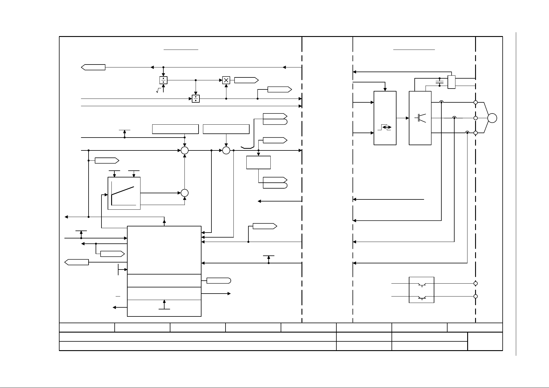
3.13 Vector control
SINAMICS G120C
422 List Manual (LH13), 04/2014, A5E33840768B AA
Fig. 3-89 6730 – Interface to the Power Module (ASM, p0300 = 1)
- 6730 -
Function diagram
87654321
fp_6730_97_05.vsd
Vector control
SINAMICS G120C
07.04.2014 V4.7
Interface to the Power Module (ASM, p0300 = 1)
[8012.3]
[6723.1]
[6799.1]
PWM
M
~
U
V
W
+ BRP
-BRN
P24
M
p1755
Kp Tn
p1764
2
[6300.1]
[6640.1]
Iq
M
[6722.7]
r1408.12
[6310.5]
[6640.5]
[6710.2]
+
[6300.8]
[6714.8]
[6799.1]
[6799.1]
[6799.1]
[2526.2]
Pre-control speed
n_act
Adaptation controller
Motor model
Stall monitoring
Model control
Vibration damping
Sign
+ or -
I_max PM
Brake control
I_max PM
Pulse enable HW
DC link voltage
Power ModuleControl Unit
U_set
U_angle
r0070
Vdc act val [V]
r0072
U_output [Vrms]
r0074
Modulat_depth [%]
f_Slip
r0065
ZSW cl-loop ctrl
r0056
r0056
.11
r0066
f_outp [Hz]
ZSW cl-loop ctrl
r0056
r0056
.07
R_stator act
r0395
r0087
Cos phi act
r0084
Flux act val [%]
[6030.8]
[6310.1] [6799.1]
Current model
Outp_ph_seq rev
p1820
p1767
U_phase act val [V]
r0089[0..2]
r0069[0..6]
I_phase act value [A]
r0063[0..2]
n_act [rpm]
p1745
Internal interface Power Module - Control Unit
+
+
+
+
+
+
ASM: Induction motor
[6714.1]
[2701.8]
Loading ...
Loading ...
Loading ...