s
SINAMICS
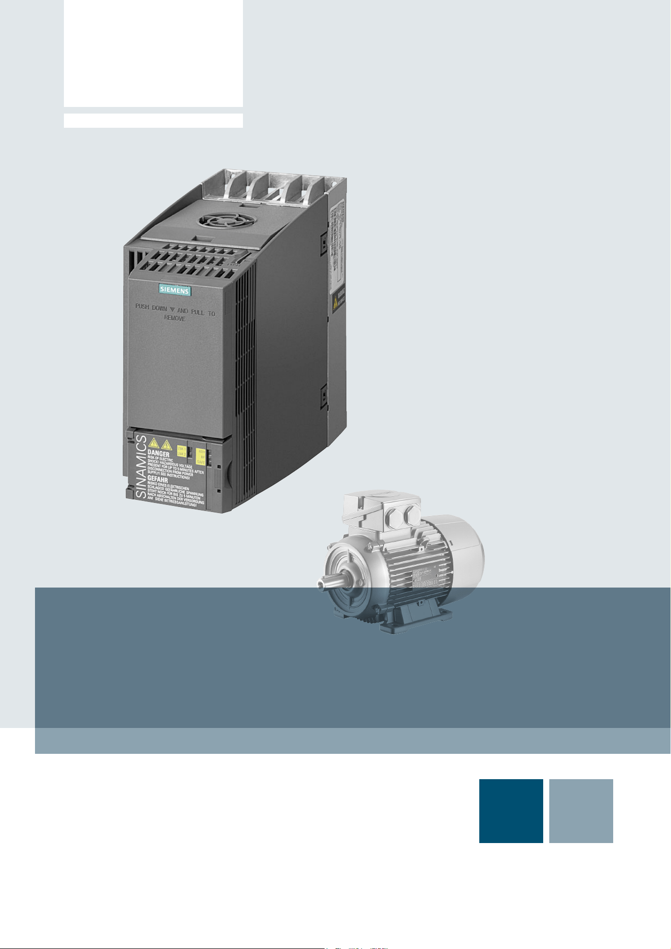
SINAMICS G120C
List Manual
04/2014Edition
Answers for industry.


Warning notice system
This Manual contains information which you must observe to ensure your own personal safety as well as to avoid
material damage. The notices referring to your personal safety are highlighted in the manual by a safety alert
symbol, notices referring only to equipment damage have no safety alert symbol. Depending on the hazard level,
warnings are indicated in a descending order as follows:
If more than one level of danger is simultaneously applicable, the warning notice for the highest level is used. A
notice warning of injury to persons with a safety alert symbol may also include a warning relating to property
damage.
Qualified personnel
The product/system described in this documentation may only be operated by personnel qualified for the specific
task in accordance with the relevant documentation for the specific task, in particular its warning notices and safety
instructions. Qualified personnel are those who, based on their training and experience, are capable of identifying
risks and avoiding potential hazards when working with these products/systems.
Proper Use of Siemens Products
Note the following:
Trademarks
All names identified with ® are registered trademarks of Siemens AG. Any other names used in this publication may
be trademarks whose use by third parties for their own purposes could violate the rights of the owner.
Disclaimer of liability
We have checked the contents of this publication for consistency with the hardware and software described. Since
variance cannot be precluded entirely, we cannot guarantee full consistency. The information given in this document
is reviewed at regular intervals and any corrections that might be necessary are made in the subsequent editions.
DANGER
indicates that death or serious injury will result if proper precautions are not taken.
WARNING
indicates that death or serious injury could result if proper precautions are not taken.
CAUTION
indicates that minor personal injury can result if proper precautions are not taken.
NOTICE
indicates that property damage can result if proper precautions are not taken.
WARNING
Siemens products are only permitted to be used for the applications listed in the catalog and in the associated
technical documentation. If third-party products and components are used, then they must be recommended or
approved by Siemens. These products can only function correctly and safely if they are transported, stored, set
up, mounted, installed, commissioned, operated and maintained correctly. The permissible ambient conditions
must be adhered to. Notes in the associated documentation must be observed.
Siemens AG
Industry Sector
Postfach 48 48
90026 NUREMBERG
GERMANY
Document order number: A5E33840768B AA
04/2014 Subject to change
Copyright © Siemens AG 2014.
All rights reserved
Legal information

SINAMICS G120C
List Manual (LH13), 04/2014, A5E33840768B AA
5
Table of contents
1 Fundamental safety instructions . . . . . . . . . . . . . . . . . . . . . . . . . . . . . . . . . . . . . . . . . . . . . . . . . . . 7
1.1 General safety instructions. . . . . . . . . . . . . . . . . . . . . . . . . . . . . . . . . . . . . . . . . . . . . . . . . . 8
1.2 Industrial security . . . . . . . . . . . . . . . . . . . . . . . . . . . . . . . . . . . . . . . . . . . . . . . . . . . . . . . . . 9
2 Parameters. . . . . . . . . . . . . . . . . . . . . . . . . . . . . . . . . . . . . . . . . . . . . . . . . . . . . . . . . . . . . . . . . . . . . 11
2.1 Overview of parameters . . . . . . . . . . . . . . . . . . . . . . . . . . . . . . . . . . . . . . . . . . . . . . . . . . . . 12
2.1.1 Explanation of the parameter list . . . . . . . . . . . . . . . . . . . . . . . . . . . . . . . . . . . . . . . . . . . . . 12
2.1.2 Number ranges of parameters . . . . . . . . . . . . . . . . . . . . . . . . . . . . . . . . . . . . . . . . . . . . . . . 22
2.2 List of parameters . . . . . . . . . . . . . . . . . . . . . . . . . . . . . . . . . . . . . . . . . . . . . . . . . . . . . . . . 25
2.3 Parameters for data sets . . . . . . . . . . . . . . . . . . . . . . . . . . . . . . . . . . . . . . . . . . . . . . . . . . . 299
2.3.1 Command Data Set (CDS). . . . . . . . . . . . . . . . . . . . . . . . . . . . . . . . . . . . . . . . . . . . . . . . . . 299
2.3.2 Drive Data Sets (DDS) . . . . . . . . . . . . . . . . . . . . . . . . . . . . . . . . . . . . . . . . . . . . . . . . . . . . . 300
2.3.3 Motor data sets (MDS) . . . . . . . . . . . . . . . . . . . . . . . . . . . . . . . . . . . . . . . . . . . . . . . . . . . . . 303
2.3.4 Power unit Data Sets (PDS). . . . . . . . . . . . . . . . . . . . . . . . . . . . . . . . . . . . . . . . . . . . . . . . . 305
2.3.5 Encoder Data Sets (EDS) . . . . . . . . . . . . . . . . . . . . . . . . . . . . . . . . . . . . . . . . . . . . . . . . . . 305
2.4 BICO parameters (connectors/binectors). . . . . . . . . . . . . . . . . . . . . . . . . . . . . . . . . . . . . . . 306
2.4.1 Binector inputs (BI). . . . . . . . . . . . . . . . . . . . . . . . . . . . . . . . . . . . . . . . . . . . . . . . . . . . . . . . 306
2.4.2 Connector inputs (CI) . . . . . . . . . . . . . . . . . . . . . . . . . . . . . . . . . . . . . . . . . . . . . . . . . . . . . . 307
2.4.3 Binector outputs (BO). . . . . . . . . . . . . . . . . . . . . . . . . . . . . . . . . . . . . . . . . . . . . . . . . . . . . . 307
2.4.4 Connector outputs (CO) . . . . . . . . . . . . . . . . . . . . . . . . . . . . . . . . . . . . . . . . . . . . . . . . . . . . 308
2.4.5 Connector/binector outputs (CO/BO) . . . . . . . . . . . . . . . . . . . . . . . . . . . . . . . . . . . . . . . . . . 310
2.5 Parameters for write protection and know-how protection . . . . . . . . . . . . . . . . . . . . . . . . . . 312
2.5.1 Parameters with "WRITE_NO_LOCK". . . . . . . . . . . . . . . . . . . . . . . . . . . . . . . . . . . . . . . . . 312
2.5.2 Parameters with "KHP_WRITE_NO_LOCK" . . . . . . . . . . . . . . . . . . . . . . . . . . . . . . . . . . . . 312
2.5.3 Parameters with "KHP_ACTIVE_READ" . . . . . . . . . . . . . . . . . . . . . . . . . . . . . . . . . . . . . . . 313
2.6 Quick commissioning (p0010 = 1) . . . . . . . . . . . . . . . . . . . . . . . . . . . . . . . . . . . . . . . . . . . . 314
3 Function diagrams . . . . . . . . . . . . . . . . . . . . . . . . . . . . . . . . . . . . . . . . . . . . . . . . . . . . . . . . . . . . . . 317
3.1 Table of contents . . . . . . . . . . . . . . . . . . . . . . . . . . . . . . . . . . . . . . . . . . . . . . . . . . . . . . . . . 318
3.2 Explanation of the function diagrams . . . . . . . . . . . . . . . . . . . . . . . . . . . . . . . . . . . . . . . . . . 322
3.3 Input/output terminals. . . . . . . . . . . . . . . . . . . . . . . . . . . . . . . . . . . . . . . . . . . . . . . . . . . . . . 327
3.4 PROFIenergy . . . . . . . . . . . . . . . . . . . . . . . . . . . . . . . . . . . . . . . . . . . . . . . . . . . . . . . . . . . . 336
3.5 PROFIdrive communication (PROFIBUS/PROFINET) . . . . . . . . . . . . . . . . . . . . . . . . . . . . 339
3.6 CANopen communication . . . . . . . . . . . . . . . . . . . . . . . . . . . . . . . . . . . . . . . . . . . . . . . . . . 353
3.7 Communication, fieldbus interface (USS, MODBUS) . . . . . . . . . . . . . . . . . . . . . . . . . . . . . 360
3.8 Internal control/status words . . . . . . . . . . . . . . . . . . . . . . . . . . . . . . . . . . . . . . . . . . . . . . . . 366
3.9 Brake control . . . . . . . . . . . . . . . . . . . . . . . . . . . . . . . . . . . . . . . . . . . . . . . . . . . . . . . . . . . . 384
3.10 Safety Integrated Basic Functions . . . . . . . . . . . . . . . . . . . . . . . . . . . . . . . . . . . . . . . . . . . . 386
3.11 Safety Integrated PROFIsafe . . . . . . . . . . . . . . . . . . . . . . . . . . . . . . . . . . . . . . . . . . . . . . . . 392

Table of contents
SINAMICS G120C
6 List Manual (LH13), 04/2014, A5E33840768B AA
3.12 Setpoint channel . . . . . . . . . . . . . . . . . . . . . . . . . . . . . . . . . . . . . . . . . . . . . . . . . . . . . . . . . 394
3.13 Vector control . . . . . . . . . . . . . . . . . . . . . . . . . . . . . . . . . . . . . . . . . . . . . . . . . . . . . . . . . . . . 403
3.14 Technology functions . . . . . . . . . . . . . . . . . . . . . . . . . . . . . . . . . . . . . . . . . . . . . . . . . . . . . . 425
3.15 Technology controller . . . . . . . . . . . . . . . . . . . . . . . . . . . . . . . . . . . . . . . . . . . . . . . . . . . . . . 427
3.16 Signals and monitoring functions . . . . . . . . . . . . . . . . . . . . . . . . . . . . . . . . . . . . . . . . . . . . . 432
3.17 Diagnostics. . . . . . . . . . . . . . . . . . . . . . . . . . . . . . . . . . . . . . . . . . . . . . . . . . . . . . . . . . . . . . 442
3.18 Data sets . . . . . . . . . . . . . . . . . . . . . . . . . . . . . . . . . . . . . . . . . . . . . . . . . . . . . . . . . . . . . . . 448
4 Faults and alarms . . . . . . . . . . . . . . . . . . . . . . . . . . . . . . . . . . . . . . . . . . . . . . . . . . . . . . . . . . . . . . . 451
4.1 Overview of faults and alarms . . . . . . . . . . . . . . . . . . . . . . . . . . . . . . . . . . . . . . . . . . . . . . . 452
4.1.1 General information . . . . . . . . . . . . . . . . . . . . . . . . . . . . . . . . . . . . . . . . . . . . . . . . . . . . . . . 452
4.1.2 Explanation of the list of faults and alarms. . . . . . . . . . . . . . . . . . . . . . . . . . . . . . . . . . . . . . 456
4.1.3 Number ranges of faults and alarms . . . . . . . . . . . . . . . . . . . . . . . . . . . . . . . . . . . . . . . . . . 461
4.2 List of faults and alarms . . . . . . . . . . . . . . . . . . . . . . . . . . . . . . . . . . . . . . . . . . . . . . . . . . . . 463
A Appendix . . . . . . . . . . . . . . . . . . . . . . . . . . . . . . . . . . . . . . . . . . . . . . . . . . . . . . . . . . . . . . . . . . . . . . 547
A.1 ASCII table (characters that can be displayed) . . . . . . . . . . . . . . . . . . . . . . . . . . . . . . . . . . 548
A.2 List of abbreviations . . . . . . . . . . . . . . . . . . . . . . . . . . . . . . . . . . . . . . . . . . . . . . . . . . . . . . . 551
Index . . . . . . . . . . . . . . . . . . . . . . . . . . . . . . . . . . . . . . . . . . . . . . . . . . . . . . . . . . . . . . . . . . . . . . . . . . 561


1 Fundamental safety instructions
1.1 General safety instructions
SINAMICS G120C
8 List Manual (LH13), 04/2014, A5E33840768B AA
1.1 General safety instructions
WARNING
Risk of death if the safety instructions and remaining risks are not carefully observed
If the safety instructions and residual risks are not observed in the associated hardware
documentation, accidents involving severe injuries or death can occur.
• Observe the safety instructions given in the hardware documentation.
• Consider the residual risks for the risk evaluation.
WARNING
Danger to life or malfunctions of the machine as a result of incorrect or changed
parameterization
As a result of incorrect or changed parameterization, machines can malfunction, which in turn
can lead to injuries or death.
• Protect the parameterization (parameter assignments) against unauthorized access.
• Respond to possible malfunctions by applying suitable measures
(e.g. EMERGENCY-STOP or EMERGENCY-OFF).

SINAMICS G120C
List Manual (LH13), 04/2014, A5E33840768B AA
9
1 Fundamental safety instructions
1.2 Industrial security
1.2 Industrial security
Note
Industrial security
Siemens provides products and solutions with industrial security functions that support the
secure operation of plants, solutions, machines, devices, and/or networks. They are important
components of a holistic industrial security concept. With this in mind, Siemens’ products and
solutions undergo continuous development. Siemens recommends strongly that you regularly
check for product updates.
To ensure that Siemens products and solutions are operated securely, suitable preventive
measures (e.g. cell protection concept) and each component must be integrated into a state-
of-the-art holistic industrial security concept. Third-party products that may be in use should
also be considered. You will find more information about industrial security at:
http://www.siemens.com/industrialsecurity
To receive information about product updates on a regular basis, register for our product
newsletter. You will find more information at:
http://support.automation.siemens.com
WARNING
Danger as a result of unsafe operating states resulting from software manipulation
Software manipulation (e.g. by viruses, Trojan horses, malware, worms) can cause unsafe
operating states to develop in your installation which can result in death, severe injuries
and/or material damage.
• Keep the software up to date.
Information and newsletters can be found at:
http://support.automation.siemens.com
• Incorporate the automation and drive components into a holistic, state-of-the-art industrial
security concept for the installation or machine.
For more information, visit:
http://www.siemens.com/industrialsecurity
• Make sure that you include all installed products into the holistic industrial security
concept.

1 Fundamental safety instructions
1.2 Industrial security
SINAMICS G120C
10 List Manual (LH13), 04/2014, A5E33840768B AA

2
SINAMICS G120C
List Manual (LH13), 04/2014, A5E33840768B AA
11
Parameters
Content
2.1 Overview of parameters 12
2.2 List of parameters 25
2.3 Parameters for data sets 299
2.4 BICO parameters (connectors/binectors) 306
2.5 Parameters for write protection and know-how protection 312
2.6 Quick commissioning (p0010 = 1) 314

2 Parameters
2.1 Overview of parameters
SINAMICS G120C
12 List Manual (LH13), 04/2014, A5E33840768B AA
2.1 Overview of parameters
2.1.1 Explanation of the parameter list
Basic structure of the parameter descriptions
The data in the following example has been chosen at random. The table below contains all
the information that can be included in a parameter description. Some of the information is
optional.
The "List of parameters" (Page 25) has the following structure:
- - - - - - - - - - - - Start of example - - - - - - - - - - - - - - - - - - - - - - - - - - - - - - - - - - - - - - - - - - - - - - - -
Description: Text
Value: 0: Name and meaning of value 0
1: Name and meaning of value 1
2: Name and meaning of value 2
etc.
Recommendation: Text
Index: [0] = Name and meaning of index 0
[1] = Name and meaning of index 1
[2] = Name and meaning of index 2
etc.
Dependency: Text
Refer to: pxxxx, rxxxx
Refer to: Fxxxxx, Axxxxx
Note: Information that might be useful.
- - - - - - - - - - - - End of example - - - - - - - - - - - - - - - - - - - - - - - - - - - - - - - - - - - - - - - - - - - - - - - -
The individual pieces of information are described in detail below.
pxxxx[0...n] BICO: Full parameter name / abbreviated name
CU/PM variants Access level: 3 Calculated: p0340 = 1 Data type: FloatingPoint32
Can be changed: C(x), U, T Scaling: p2002 Dyn. index: CDS, p0170
Unit group: 6_2 Unit selection: p0505 Func. diagram: 8070
Min Max Factory setting
0.00 [Nm] 10.00 [Nm] 0.00 [Nm]
Bit field: Bit Signal name 1 signal 0 signal FP
00 Name and meaning of bit 0 Yes no 8060
01 Name and meaning of bit 1 Yes no -
02 Name and meaning of bit 2 Yes no 8052
etc.
Danger: Warning: Caution: Safety notices with a warning triangle
Notice: Safety notice without a warning triangle

SINAMICS G120C
List Manual (LH13), 04/2014, A5E33840768B AA
13
2 Parameters
2.1 Overview of parameters
pxxxx[0...n] Parameter number
The parameter number is made up of a "p" or "r", followed by the parameter number and the
index or bit field (optional).
Examples of the representation in the parameter list:
Other examples of the notation in the documentation:
The following applies to adjustable parameters:
The parameter value as delivered is specified under "Factory setting" with the relevant unit in
square brackets. The value can be adjusted within the range defined by "Min" and "Max".
The term "linked parameterization" is used in cases where changes to adjustable parameters
affect the settings of other parameters.
Linked parameterization can occur, for example, as a result of the following actions and
parameters:
• Setting the PROFIBUS telegram (BICO interconnection)
p0922
• Set component lists
p0230, p0300, p0301, p0400
• Automatic calculation and pre-assignment
p0340, p3900
• Restoring the factory settings
p0970
The following applies to display parameters:
The fields "Min", "Max" and "Factory setting" are specified with a dash "-" and the relevant unit
in square brackets.
• p... Adjustable parameters (read and write parameters)
• r... Display parameters (read only)
• p0918 Adjustable parameter 918
• p2051[0...13] Adjustable parameter 2051, indices 0 to 13
• p1001[0...n] Adjustable parameter 1001, indices 0 to n (n = configurable)
• r0944 Display parameter 944
• r2129.0...15 Display parameter 2129 with bit field from bit 0 (smallest bit) to bit 15
(largest bit)
• p1070[1] Adjustable parameter 1070, index 1
• p2098[1].3 Adjustable parameter 2098, index 1 bit 3
• p0795.4 Adjustable parameter 795, bit 4
Note
The parameter list can contain parameters that are not visible in the expert lists of the particular
commissioning software (e.g. parameters for trace functions).

2 Parameters
2.1 Overview of parameters
SINAMICS G120C
14 List Manual (LH13), 04/2014, A5E33840768B AA
BICO: Full parameter name / abbreviated name
The following abbreviations can appear in front of the BICO parameter name:
G120C variants
Specifies for which G120C variants (communication) the parameter is valid is. If no G120C
variant is listed, then the parameter is valid for all variants.
The following information relating to "G120C variants" can be displayed under the parameter
number:
• BI: Binector Input
This parameter is used for selecting the source of a digital signal.
• BO: Binector output
This parameter is available as a digital signal for interconnection with other
parameters.
• CI: Connector Input
This parameter is used for selecting the source of an "analog" signal.
• CO: Connector output
This parameter is available as an "analog" signal for interconnection with other
parameters.
• CO/BO: Connector/Binector Output
This parameter is available as an "analog" and digital signal for interconnection
with other parameters.
Note
A BICO input (BI/CI) cannot be interconnected with just any BICO output (BO/CO, signal
source).
When interconnecting a BICO input using the commissioning software, only the corresponding
possible signal sources are listed.
Function diagrams 1020 ... 1030 explain the symbols for BICO parameters and how to deal
with BICO technology.
Table 2-1 Information in the "CU/PM variants" field
CU/PM variants Meaning
All G120C variants have this parameter.
G120C_CAN G120C with CAN interface
G120C_DP
G120C with PROFIBUS interface
G120C_PN
G120C with PROFINET interface
G120C_USS
G120C with USS interface

SINAMICS G120C
List Manual (LH13), 04/2014, A5E33840768B AA
15
2 Parameters
2.1 Overview of parameters
Access level
Specifies the minimum access level required to be able to display and change the relevant
parameter. The required access level can be set using p0003.
The system uses the following access levels:
• 1: Standard (not adjustable, included in p0003 = 3)
• 2: Extended (not adjustable, included in p0003 = 3)
• 3: Expert
• 4: Service
Parameters with this access level are password protected.
Calculated
Specifies whether the parameter is influenced by automatic calculations.
p0340 determines which calculations are to be performed:
• p0340 = 1 includes the calculations from p0340 = 2, 3, 4, 5.
• p0340 = 2 calculates the motor parameters (p0350 ... p0360, p0625).
• p0340 = 3 includes the calculations from p0340 = 4, 5.
• p0340 = 4 only calculates the controller parameters.
• p0340 = 5 only calculates the controller limits.
Parameters with a reference to p0340 after "Calculated" depend on the Power Module being
used and the motor. In this case, the values at "Factory setting" do not correspond to the actual
values because these values are calculated during the commissioning. This also applies to the
motor parameters.
Note
Parameter p0003 is CU-specific (belongs to the Control Unit).
A higher access level will also include the functions of the lower levels.
Note
For p3900 > 0, p0340 = 1 is also called automatically.
After p1900 = 1, 2, p0340 = 3 is also called automatically.

2 Parameters
2.1 Overview of parameters
SINAMICS G120C
16 List Manual (LH13), 04/2014, A5E33840768B AA
Data type
The information on the data type can consist of the following two items (separated by a slash):
• First item
Data type of the parameter.
• Second item (for binector or connector input only)
Data type of the signal source to be interconnected (binector-/connector output).
Parameters can have the following data types:
Depending on the data type of the BICO input parameter (signal sink) and BICO output
parameter (signal source), the following combinations are possible when creating BICO
interconnections:
• Integer8 I8 8-bit integer number
• Integer16 I16 16-bit integer number
• Integer32 I32 32-bit integer number
• Unsigned8 U8 8 bits without sign
• Unsigned16 U16 16 bits without sign
• Unsigned32 U32 32 bits without sign
• FloatingPoint32 Float 32-bit floating point number
Table 2-2 Possible combinations of BICO interconnections
BICO input parameter
CI parameter BI parameter
BICO output parameter Unsigned32 /
Integer16
Unsigned32 /
Integer32
Unsigned32 /
FloatingPoint32
Unsigned32 /
Binary
CO: Unsigned8 x x – –
CO: Unsigned16 x x – –
CO: Unsigned32 x x – –
CO: Integer16 x x r2050 –
CO: Integer32 x x r2060 –
CO: FloatingPoint32 x x x –
BO: Unsigned8 – – – x
BO: Unsigned16 – – – x
BO: Unsigned32 – – – x
BO: Integer16 – – – x
BO: Integer32 – – – x
BO: FloatingPoint32 – – – –
Legend: x :
–:
rxxxx:
BICO interconnection permitted
BICO interconnection not permitted
BICO interconnection is only permitted for the specified CO parameters

SINAMICS G120C
List Manual (LH13), 04/2014, A5E33840768B AA
17
2 Parameters
2.1 Overview of parameters
Can be changed
The "-" sign indicates that the parameter can be changed in any object state and that the
change will be effective immediately.
The information "C(x), T, U" ((x): optional) means that the parameter can be changed only in
the specified drive unit state and that the change will not take effect until the unit switches to
another state. This can be a single state or multiple states.
The following states are available:
Scaling
Specification of the reference variable with which a signal value is automatically converted for
a BICO interconnection.
The following reference variables are available:
• p2000 ... p2006: Reference speed, reference voltage, etc.
• PERCENT: 1.0 = 100 %
• 4000H: 4000 hex = 100 %
• C(x) commissioning C: Commissioning
Drive commissioning is in progress (p0010 > 0).
Pulses cannot be enabled.
The parameter can only be changed in the following drive commissioning settings
(p0010 > 0):
• C: Can be changed for all settings p0010 > 0.
• C(x): Can only be changed for the settings p0010 = x.
A modified parameter value does not take effect until drive commissioning mode is
exited with p0010 = 0.
• UOperation U: Run
Pulses are enabled.
• T Ready T: Ready to run
The pulses are not enabled and the status "C(x)" is not active.

2 Parameters
2.1 Overview of parameters
SINAMICS G120C
18 List Manual (LH13), 04/2014, A5E33840768B AA
Dyn. index (dynamic index)
For parameters with a dynamic index [0...n], the following information is specified here:
• Data set (if available).
• Parameter for the number of indices (n = number - 1).
The following information can be contained in this field:
• "CDS, p0170" (Command Data Set, CDS count)
Example:
p1070[0] main setpoint [command data set 0]
p1070[1] main setpoint [command data set 1], etc.
• "DDS, p0180" (Drive Data Set, DDS count)
• "EDS, p0140" (Encoder Data Set, EDS count)
• "MDS, p0130" (Motor Data Set, MDS count)
• "PDS, p0120" (Power unit Data Set, PDS count)
Data sets can only be created and deleted when p0010 = 15.
Unit group and unit selection
The standard unit of a parameter is specified in square brackets after the values for "Min",
"Max", and "Factory setting".
For parameters where the unit can be switched over, the specifications for "Unit group" and
"Unit selection" determine the group to which this parameter belongs and with which parameter
the unit can be changed over.
Example:
Unit group: 7_1, unit selection: p0505
The parameter belongs to unit group 7_1 and the unit can be changed over using p0505.
All the potential unit groups and possible unit selections are listed below.
Note
Information on the data sets can be taken from the following references:
Operating Instructions SINAMICS G120 Frequency Converter G120C.
Table 2-3 Unit group (p0100)
Unit group Unit selection for p0100 = Reference variable for %
012
7_4 Nm lbf ft Nm -
14_6 kW hp kW -
25_1 kg m
2
lb ft
2
kg m
2
-
27_1 kg lb kg -
28_1 Nm/A lbf ft/A Nm/A -

SINAMICS G120C
List Manual (LH13), 04/2014, A5E33840768B AA
19
2 Parameters
2.1 Overview of parameters
Function diagram
The parameter is included in this function diagram. The structure of the parameter function and
its relationship with other parameters is shown in the specified function diagram.
Table 2-4 Unit group (p0505)
Unit group Unit selection for p0505 = Reference variable for %
1234
2_1 Hz % Hz % p2000
3_1 1 rpm % 1 rpm % p2000
5_1 Vrms % Vrms % p2001
5_2 V % V % p2001
5_3 V % V % p2001
6_2 Arms % Arms % p2002
6_5 A % A % p2002
7_1 Nm % lbf ft % p2003
7_2 Nm Nm lbf ft lbf ft -
14_5 kW % hp % r2004
14_10 kW kW hp hp -
21_1 °C °C °F °F -
21_2 K K °F °F -
39_1 1/s
2
%1/s
2
% p2007
Table 2-5 Unit group (p0595)
Unit group Unit selection for p0595 = Reference variable for %
Value Unit
9_1 The values that can be set and the technological units are shown in p0595.

2 Parameters
2.1 Overview of parameters
SINAMICS G120C
20 List Manual (LH13), 04/2014, A5E33840768B AA
Parameter values
Description
Explanation of the function of a parameter
Values
Lists the possible values of a parameter.
Recommendation
Information about recommended settings.
Index
The name and meaning of each individual index is specified for indexed parameters.
The following applies to the values (Min, Max, Factory setting) for indexed adjustable
parameters:
• Min, Max:
The adjustment range and unit apply to all indices.
• Factory setting:
When all indices have the same factory setting, index 0 is specified with the unit to
represent all indices.
When the indices have different factory settings, they are all listed individually with the unit.
Min Minimum value of the parameter [unit]
Max Maximum value of the parameter [unit]
Factory setting Value when delivered [unit]
In the case of a binector/connector input, the signal source of the
default BICO interconnection is specified. A non-indexed connector
output is assigned the index [0].
A different value may be displayed for certain parameters (e.g. p1800)
at the initial commissioning stage or when establishing the factory
settings.
Reason:
The setting of these parameters is determined by the operating
environment of the Control Unit (e.g. depending on converter type,
power unit).

SINAMICS G120C
List Manual (LH13), 04/2014, A5E33840768B AA
21
2 Parameters
2.1 Overview of parameters
Bit field
For parameters with bit fields, the following information is provided about each bit:
• Bit number and signal name
• Meaning for signal states 1 and 0
• Function diagram (FP) (optional).
The signal is shown in this function diagram.
Dependency
Conditions that must be fulfilled in conjunction with this parameter. Also includes special effects
that can occur between this parameter and others.
Where necessary, "Refer to:" indicates the following information:
• List of other relevant parameters to be considered.
• List of faults and alarms to be considered.
Safety guidelines
Important information that must be observed to avoid the risk of physical injury or material
damage.
Information that must be observed to avoid any problems.
Information that the user may find useful.
Danger The description of this safety notice can be found at the beginning of this
manual (see "Legal information" (Page 4)).
Warning The description of this safety notice can be found at the beginning of this
manual (see "Legal information" (Page 4)).
Caution The description of this safety notice can be found at the beginning of this
manual (see "Legal information" (Page 4)).
Notice The description of this safety notice can be found at the beginning of this
manual (see "Legal information" (Page 4)).
Note Information that the user may find useful.

2 Parameters
2.1 Overview of parameters
SINAMICS G120C
22 List Manual (LH13), 04/2014, A5E33840768B AA
2.1.2 Number ranges of parameters
Parameters are grouped into the following number ranges:
Note
The following number ranges represent an overview for all the parameters available for the
SINAMICS drive family.
The parameters for the product described in this List Manual are described in detail in "List of
parameters" (Page 25).
Table 2-6 Number ranges for SINAMICS
Range Description
From To
0000 0099 Display and operation
0100 0199 Commissioning
0200 0299 Power section
0300 0399 Motor
0400 0499 Encoder
0500 0599 Technology and units, motor-specific data, probes
0600 0699 Thermal monitoring, maximum current, operating hours, motor data,
central probe
0700 0799 Control Unit terminals, measuring sockets
0800 0839 CDS, DDS data sets, motor changeover
0840 0879 Sequence control (e.g. signal source for ON/OFF1)
0880 0899 ESR, parking, control and status words
0900 0999 PROFIBUS/PROFIdrive
1000 1199 Setpoint channel (e.g. ramp-function generator)
1200 1299 Functions (e.g. motor holding brake)
1300 1399 U/f control
1400 1799 Closed-loop control
1800 1899 Gating unit
1900 1999 Power unit and motor identification
2000 2009 Reference values
2010 2099 Communication (fieldbus)
2100 2139 Faults and alarms
2140 2199 Signals and monitoring
2200 2359 Technology controller
2360 2399 Staging, hibernation
2500 2699 Position control (LR) and basic positioning (EPOS)
2700 2719 Reference values, display

SINAMICS G120C
List Manual (LH13), 04/2014, A5E33840768B AA
23
2 Parameters
2.1 Overview of parameters
2720 2729 Load gearbox
2800 2819 Logic operations
2900 2930 Fixed values (e. g. percentage, torque)
3000 3099 Motor identification results
3100 3109 Real-time clock (RTC)
3110 3199 Faults and alarms
3200 3299 Signals and monitoring
3400 3659 Infeed closed-loop control
3660 3699 Voltage Sensing Module (VSM), Braking Module internal
3700 3779 Advanced Positioning Control (APC)
3780 3819 Synchronization
3820 3849 Friction characteristic
3850 3899 Functions (e. g. long stator)
3900 3999 Management
4000 4599 Terminal Board, Terminal Module (e. g. TB30, TM31)
4600 4699 Sensor Module
4700 4799 Trace
4800 4849 Function generator
4950 4999 OA application
5000 5169 Spindle diagnostics
5200 5230 Current setpoint filter 5 ... 10 (r0108.21)
5400 5499 System droop control (e. g. shaft generator)
5500 5599 Dynamic grid support (solar)
5600 5614 PROFIenergy
5900 6999 SINAMICS GM/SM/GL/SL
7000 7499 Parallel connection of power units
7500 7599 SINAMICS SM120
7700 7729 External messages
7770 7789 NVRAM, system parameters
7800 7839 EEPROM read/write parameters
7840 8399 Internal system parameters
8400 8449 Real-time clock (RTC)
8500 8599 Data and macro management
8600 8799 CAN bus
8800 8899 Communication Board Ethernet (CBE), PROFIdrive
Table 2-6 Number ranges for SINAMICS, continued
Range Description
From To

2 Parameters
2.1 Overview of parameters
SINAMICS G120C
24 List Manual (LH13), 04/2014, A5E33840768B AA
8900 8999 Industrial Ethernet, PROFINET, CBE20
9000 9299 topology
9300 9399 Safety Integrated
9400 9499 Parameter consistency and storage
9500 9899 Safety Integrated
9900 9949 topology
9950 9999 Diagnostics, internal
10000 10199 Safety Integrated
11000 11299 Free technology controller 0, 1, 2
20000 20999 Free function blocks (FBLOCKS)
21000 25999 Drive Control Chart (DCC)
50000 53999 SINAMICS DC MASTER (closed-loop DC current control)
61000 61001 PROFINET
Table 2-6 Number ranges for SINAMICS, continued
Range Description
From To

SINAMICS G120C
List Manual (LH13), 04/2014, A5E33840768B AA
25
2 Parameters
2.2 List of parameters
2.2 List of parameters
Product: SINAMICS G120C, Version: 4702900, Language: eng
Objects: G120C_CAN, G120C_DP, G120C_PN, G120C_USS
Description: Operating display for the drive.
Value: 0: Operation - everything enabled
10: Operation - set "enable setpoint" = "1"
12: Operation - RFG frozen, set "RFG start" = "1"
13: Operation - set "enable RFG" = "1"
14: Operation - MotID, excit. running
15: Operation - open brake (p1215)
16: Operation - withdraw braking with OFF1 using "ON/OFF1" = "1"
17: Operation - braking with OFF3 can only be interrupted with OFF2
18: Operation - brake on fault, remove fault, acknowledge
19: Operation - DC braking active (p1230, p1231)
21: Ready for operation - set "Operation enable" = "1" (p0852)
22: Ready for operation - de-magnetizing running (p0347)
31: Ready for switching on - set "ON/OFF1" = "0/1" (p0840)
35: Switching on inhibited - carry out first commissioning (p0010)
41: Switching on inhibited - set "ON/OFF1" = "0" (p0840)
42: Switching on inhibited - set "OC/OFF2" = "1" (p0844, p0845)
43: Switching on inhibited - set "OC/OFF3" = "1" (p0848, p0849)
45: Switching on inhibited - rectify fault, acknowledge fault, STO
46: Switching on inhibited - exit comm mode (p0010)
70: Initialization
200: Wait for booting/partial booting
Dependency: Refer to: r0046
Notice: For several missing enable signals, the corresponding value with the highest number is displayed.
Note: OC: Operating condition
RFG: Ramp-function generator
COMM: Commissioning
MotID: Motor data identification
Description: Sets the access level to read and write parameters.
Value: 3: Expert
4: Service
Note: A higher set access level also includes the lower one.
Access level 3 (experts):
Expert know-how is required for these parameters (e.g. BICO parameterization).
Access level 4 (service):
For these parameters, it is necessary that authorized service personnel enter the appropriate password (p3950).
r0002 Drive operating display / Drv op_display
Access level: 2 Calculated: - Data type: Integer16
Can be changed: - Scaling: - Dyn. index: -
Units group: - Unit selection: - Func. diagram: -
Min Max Factory setting
0 200 -
p0003 Access level / Acc_level
Access level: 1 Calculated: - Data type: Integer16
Can be changed: C, U, T Scaling: - Dyn. index: -
Units group: - Unit selection: - Func. diagram: -
Min Max Factory setting
3 4 3

2 Parameters
2.2 List of parameters
SINAMICS G120C
26 List Manual (LH13), 04/2014, A5E33840768B AA
Description: Sets the parameter filter to commission a drive.
Setting this parameter filters out the parameters that can be written into in the various commissioning steps.
Value: 0: Ready
1: Quick commissioning
2: Power unit commissioning
3: Motor commissioning
5: Technological application/units
15: Data sets
29: Only Siemens int
30: Parameter reset
39: Only Siemens int
49: Only Siemens int
95: Safety Integrated commissioning
Dependency: Refer to: r3996
Notice: When the parameter is reset to a value of 0, short-term communication interruptions may occur.
Note: The drive can only be powered up outside the drive commissioning (inverter enable). To realize this, this parameter
must be set to 0.
By setting p3900 to a value other than 0, the quick commissioning is completed, and this parameter is automatically
reset to 0.
Procedure for "Reset parameter": Set p0010 to 30 and p0970 to 1.
Once the Control Unit has been booted up for the first time, the motor parameters suitable for the power unit have
been defined, and the control parameters have been calculated accordingly, p0010 is automatically reset to 0.
p0010 = 3 is used for the subsequent commissioning of additional drive data sets (creating data sets: see p0010 =
15).
p0010 = 29, 39, 49: Only for internal Siemens use!
Description: Runs the corresponding macro files.
Notice: After the value has been modified, no further parameter modifications can be made and the status is shown in r3996.
Modifications can be made again when r3996 = 0.
When executing a specific macro, the corresponding programmed settings are made and become active.
Note: Macros available as standard are described in the technical documentation of the particular product.
p0010 Drive commissioning parameter filter / Drv comm. par_filt
Access level: 1 Calculated: - Data type: Integer16
Can be changed: C(1), T Scaling: - Dyn. index: -
Units group: - Unit selection: - Func. diagram: 2800, 2818
Min Max Factory setting
0 95 1
p0015 Macro drive unit / Macro drv unit
G120C_CAN
G120C_USS
Access level: 1 Calculated: - Data type: Unsigned32
Can be changed: C, C(1) Scaling: - Dyn. index: -
Units group: - Unit selection: - Func. diagram: -
Min Max Factory setting
0 999999 12
p0015 Macro drive unit / Macro drv unit
G120C_DP
G120C_PN
Access level: 1 Calculated: - Data type: Unsigned32
Can be changed: C, C(1) Scaling: - Dyn. index: -
Units group: - Unit selection: - Func. diagram: -
Min Max Factory setting
0 999999 7

SINAMICS G120C
List Manual (LH13), 04/2014, A5E33840768B AA
27
2 Parameters
2.2 List of parameters
Description: Displays the firmware version of the Control Unit.
Dependency: Refer to: r0197, r0198
Note: Example:
The value 1010100 should be interpreted as V01.01.01.00.
Description: Displays the currently smoothed speed setpoint at the input of the speed controller or U/f characteristic (after the
interpolator).
Dependency: Refer to: r0060
Note: Smoothing time constant = 100 ms
The signal is not suitable as a process quantity and may only be used as a display quantity.
The speed setpoint is available smoothed (r0020) and unsmoothed (r0060).
Description: Displays the smoothed actual value of the motor speed.
For U/f control and when slip compensation is deactivated (see p1335), the synchronous speed to the output
frequency is shown in r0021.
Dependency: Refer to: r0022, r0063
Note: Smoothing time constant = 100 ms
The signal is not suitable as a process quantity and may only be used as a display quantity.
The speed actual value is available smoothed (r0021, r0022) and unsmoothed (r0063).
For U/f control, the mechanical speed calculated from the output frequency and the slip is shown in r0063[2] even if
slip compensation is deactivated.
Description: Displays the smoothed actual value of the motor speed.
r0022 is identical to r0021, however, it always has units of rpm and contrary to r0021 cannot be changed over.
For U/f control and when slip compensation is deactivated (see p1335), the synchronous speed to the output
frequency is shown in r0022.
Dependency: Refer to: r0021, r0063
Note: Smoothing time constant = 100 ms
The signal is not suitable as a process quantity and may only be used as a display quantity.
r0018 Control Unit firmware version / CU FW version
Access level: 3 Calculated: - Data type: Unsigned32
Can be changed: - Scaling: - Dyn. index: -
Units group: - Unit selection: - Func. diagram: -
Min Max Factory setting
0 4294967295 -
r0020 Speed setpoint smoothed / n_set smth
Access level: 2 Calculated: - Data type: FloatingPoint32
Can be changed: - Scaling: p2000 Dyn. index: -
Units group: 3_1 Unit selection: p0505 Func. diagram: 5020, 6799
Min Max Factory setting
- [rpm] - [rpm] - [rpm]
r0021 CO: Actual speed smoothed / n_act smooth
Access level: 2 Calculated: - Data type: FloatingPoint32
Can be changed: - Scaling: p2000 Dyn. index: -
Units group: 3_1 Unit selection: p0505 Func. diagram: 6799
Min Max Factory setting
- [rpm] - [rpm] - [rpm]
r0022 Speed actual value rpm smoothed / n_act rpm smooth
Access level: 3 Calculated: - Data type: FloatingPoint32
Can be changed: - Scaling: p2000 Dyn. index: -
Units group: - Unit selection: - Func. diagram: 6799
Min Max Factory setting
- [rpm] - [rpm] - [rpm]

2 Parameters
2.2 List of parameters
SINAMICS G120C
28 List Manual (LH13), 04/2014, A5E33840768B AA
The speed actual value is available smoothed (r0021, r0022) and unsmoothed (r0063).
For U/f control, the mechanical speed calculated from the output frequency and the slip is shown in r0063[2] even if
slip compensation is deactivated.
Description: Displays the smoothed converter frequency.
Dependency: Refer to: r0066
Note: Smoothing time constant = 100 ms
The signal is not suitable as a process quantity and may only be used as a display quantity.
The output frequency is available smoothed (r0024) and unsmoothed (r0066).
Description: Displays the smoothed output voltage of the power unit.
Dependency: Refer to: r0072
Note: Smoothing time constant = 100 ms
The signal is not suitable as a process quantity and may only be used as a display quantity.
The output voltage is available smoothed (r0025) and unsmoothed (r0072).
Description: Displays the smoothed actual value of the DC link voltage.
Dependency: Refer to: r0070
Notice: When measuring a DC link voltage < 200 V, for the Power Module a valid measured value is not supplied. In this
case, when an external 24 V power supply is connected, a value of approx. 24 V is displayed in the display
parameter.
Note: Smoothing time constant = 100 ms
The signal is not suitable as a process quantity and may only be used as a display quantity.
The DC link voltage is available smoothed (r0026) and unsmoothed (r0070).
r0026 sets itself to the lower value of the pulsating DC link voltage.
Description: Displays the smoothed absolute actual current value.
Dependency: Refer to: r0068
r0024 Output frequency smoothed / f_outp smooth
Access level: 3 Calculated: - Data type: FloatingPoint32
Can be changed: - Scaling: p2000 Dyn. index: -
Units group: - Unit selection: - Func. diagram: 5300, 5730, 6300,
6799
Min Max Factory setting
- [Hz] - [Hz] - [Hz]
r0025 CO: Output voltage smoothed / U_outp smooth
Access level: 2 Calculated: - Data type: FloatingPoint32
Can be changed: - Scaling: p2001 Dyn. index: -
Units group: - Unit selection: - Func. diagram: 5730, 6300, 6799
Min Max Factory setting
- [Vrms] - [Vrms] - [Vrms]
r0026 CO: DC link voltage smoothed / Vdc smooth
Access level: 2 Calculated: - Data type: FloatingPoint32
Can be changed: - Scaling: p2001 Dyn. index: -
Units group: - Unit selection: - Func. diagram: 6799
Min Max Factory setting
- [V] - [V] - [V]
r0027 CO: Absolute actual current smoothed / I_act abs val smth
Access level: 2 Calculated: - Data type: FloatingPoint32
Can be changed: - Scaling: p2002 Dyn. index: -
Units group: - Unit selection: - Func. diagram: 5730, 6799, 8850,
8950
Min Max Factory setting
- [Arms] - [Arms] - [Arms]

SINAMICS G120C
List Manual (LH13), 04/2014, A5E33840768B AA
29
2 Parameters
2.2 List of parameters
Notice: This smoothed signal is not suitable for diagnostics or evaluation of dynamic operations. In this case, the
unsmoothed value should be used.
Note: Smoothing time constant = 300 ms
The signal is not suitable as a process quantity and may only be used as a display quantity.
The absolute current actual value is available smoothed (r0027) and unsmoothed (r0068).
Description: Displays the smoothed actual value of the modulation depth.
Dependency: Refer to: r0074
Note: Smoothing time constant = 100 ms
The signal is not suitable as a process quantity and may only be used as a display quantity.
The modulation depth is available smoothed (r0028) and unsmoothed (r0074).
Description: Displays the smoothed field-generating actual current.
Dependency: Refer to: r0076
Note: Smoothing time constant = 300 ms
The signal is not suitable as a process quantity and may only be used as a display quantity.
The field-generating current actual value is available smoothed (r0029) and unsmoothed (r0076).
Description: Displays the smoothed torque-generating actual current.
Dependency: Refer to: r0078
Note: Smoothing time constant = 300 ms
The signal is not suitable as a process quantity and may only be used as a display quantity.
The torque-generating current actual value is available smoothed (r0030) and unsmoothed (r0078).
Description: Displays the smoothed torque actual value.
Dependency: Refer to: r0080
Note: Smoothing time constant = 100 ms
The signal is not suitable as a process quantity and may only be used as a display quantity.
The torque actual value is available smoothed (r0031) and unsmoothed (r0080).
r0028 Modulation depth smoothed / Mod_depth smth
Access level: 4 Calculated: - Data type: FloatingPoint32
Can be changed: - Scaling: p2002 Dyn. index: -
Units group: - Unit selection: - Func. diagram: 5730, 6799, 8950
Min Max Factory setting
- [%] - [%] - [%]
r0029 Current actual value field-generating smoothed / Id_act smooth
Access level: 4 Calculated: - Data type: FloatingPoint32
Can be changed: - Scaling: p2002 Dyn. index: -
Units group: - Unit selection: - Func. diagram: 6799
Min Max Factory setting
- [Arms] - [Arms] - [Arms]
r0030 Current actual value torque-generating smoothed / Iq_act smooth
Access level: 4 Calculated: - Data type: FloatingPoint32
Can be changed: - Scaling: p2002 Dyn. index: -
Units group: - Unit selection: - Func. diagram: 6799
Min Max Factory setting
- [Arms] - [Arms] - [Arms]
r0031 Actual torque smoothed / M_act smooth
Access level: 2 Calculated: - Data type: FloatingPoint32
Can be changed: - Scaling: p2003 Dyn. index: -
Units group: 7_1 Unit selection: p0505 Func. diagram: 5730, 6799
Min Max Factory setting
- [Nm] - [Nm] - [Nm]

2 Parameters
2.2 List of parameters
SINAMICS G120C
30 List Manual (LH13), 04/2014, A5E33840768B AA
Description: Displays the smoothed actual value of the active power.
Dependency: Refer to: r0082
Notice: This smoothed signal is not suitable for diagnostics or evaluation of dynamic operations. In this case, the
unsmoothed value should be used.
Note: Power delivered at the motor shaft.
The active power is available smoothed (r0032 with 100 ms) and unsmoothed (r0082).
Description: Displays the smoothed torque utilization as a percentage.
Dependency: This parameter is only available for vector control. For U/f control r0033 = 0 %.
Note: Smoothing time constant = 100 ms
The signal is not suitable as a process quantity and may only be used as a display quantity.
The torque utilization is available smoothed (r0033) and unsmoothed (r0081).
For M_set total (r0079) > 0, the following applies:
- Required torque = M_set total
- Actual torque limit = M_max upper effective (r1538)
For M_set total (r0079) <= 0, the following applies:
- Required torque = - M_set total
- Actual torque limit = - M_max lower effective (r1539)
For the actual torque limit = 0, the following applies: r0033 = 100 %
For the actual torque limit < 0, the following applies: r0033 = 0 %
Description: Displays the motor utilization from motor temperature model 1 (I2t).
Dependency: The thermal motor utilization is only determined for permanent-magnet synchronous motors when the motor
temperature model 1 (I2t) is activated.
For motor temperature model 1 (I2t) (p0612.0 = 1), the following applies:
- r0034 = (motor model temperature - 40 K) / (p0605 - 40 K) * 100 %
Refer to: p0611, p0612, p0615
Notice: After the drive is switched on, the system starts to determine the motor temperature with an assumed model value.
This means that the value for the motor utilization is only valid after a stabilization time.
Note: Smoothing time constant = 100 ms
The signal is not suitable as a process quantity and may only be used as a display quantity.
For r0034 = -200.0 %, the following applies:
The value is invalid (e.g. the motor temperature model is not activated or has been incorrectly parameterized).
r0032 CO: Active power actual value smoothed / P_actv_act smth
Access level: 2 Calculated: - Data type: FloatingPoint32
Can be changed: - Scaling: r2004 Dyn. index: -
Units group: 14_10 Unit selection: p0505 Func. diagram: 5730, 6799, 8750,
8850, 8950
Min Max Factory setting
- [kW] - [kW] - [kW]
r0033 Torque utilization smoothed / M_util smooth
Access level: 4 Calculated: - Data type: FloatingPoint32
Can be changed: - Scaling: PERCENT Dyn. index: -
Units group: - Unit selection: - Func. diagram: 8012
Min Max Factory setting
- [%] - [%] - [%]
r0034 CO: Motor utilization thermal / Mot_util therm
Access level: 2 Calculated: - Data type: FloatingPoint32
Can be changed: - Scaling: PERCENT Dyn. index: -
Units group: - Unit selection: - Func. diagram: 8017
Min Max Factory setting
- [%] - [%] - [%]

SINAMICS G120C
List Manual (LH13), 04/2014, A5E33840768B AA
31
2 Parameters
2.2 List of parameters
Description: Display and connector output for the actual temperature in the motor.
Note: For r0035 not equal to -200.0 °C, the following applies:
- this temperature display is valid.
- a KTY sensor is connected.
- for induction motors, the thermal motor model is activated (p0601 = 0).
For r0035 equal to -200.0 °C, the following applies:
- this temperature display is not valid (temperature sensor error).
- A PTC sensor or bimetallic NC contact is connected.
- for synchronous motors, the thermal motor model is activated (p0601 = 0).
Description: Displays the power unit overload determined using the I2t calculation.
A current reference value is defined for the I2t monitoring of the power unit. It represents the current that can be
conducted by the power unit without any influence of the switching losses (e.g. the continuously permissible current
of the capacitors, inductances, busbars, etc.).
If the I2t reference current of the power unit is not exceeded, then an overload (0 %) is not displayed.
In the other case, the degree of thermal overload is calculated, whereby 100% results in a trip.
Dependency: Refer to: p0290
Description: Display and connector output for the temperature in the power unit.
Index: [0] = Inverter maximum value
[1] = Depletion layer maximum value
[2] = Rectifier maximum value
[3] = Air intake
[4] = Interior of power unit
[5] = Inverter 1
[6] = Inverter 2
[7...10] = Reserved
[11] = Rectifier 1
[12] = Reserved
[13] = Depletion layer 1
[14] = Depletion layer 2
[15] = Depletion layer 3
[16] = Depletion layer 4
[17] = Depletion layer 5
[18] = Depletion layer 6
[19] = Reserved
Notice: Only for internal Siemens troubleshooting.
r0035 CO: Motor temperature / Mot temp
Access level: 2 Calculated: - Data type: FloatingPoint32
Can be changed: - Scaling: p2006 Dyn. index: -
Units group: 21_1 Unit selection: p0505 Func. diagram: 8016, 8017
Min Max Factory setting
- [°C] - [°C] - [°C]
r0036 CO: Power unit overload I2t / PU overload I2t
Access level: 3 Calculated: - Data type: FloatingPoint32
Can be changed: - Scaling: PERCENT Dyn. index: -
Units group: - Unit selection: - Func. diagram: 8014
Min Max Factory setting
- [%] - [%] - [%]
r0037[0...19] CO: Power unit temperatures / PU temperatures
Access level: 4 Calculated: - Data type: FloatingPoint32
Can be changed: - Scaling: p2006 Dyn. index: -
Units group: 21_1 Unit selection: p0505 Func. diagram: 8014
Min Max Factory setting
- [°C] - [°C] - [°C]

2 Parameters
2.2 List of parameters
SINAMICS G120C
32 List Manual (LH13), 04/2014, A5E33840768B AA
Note: The value of -200 indicates that there is no measuring signal.
r0037[0]: Maximum value of the inverter temperatures (r0037[5...10]).
r0037[1]: Maximum value of the depletion layer temperatures (r0037[13...18]).
r0037[2]: Maximum value of the rectifier temperatures (r0037[11...12]).
The maximum value is the temperature of the hottest inverter, depletion layer, or rectifier.
r0037[2, 3, 6, 11, 14...18] is only relevant for chassis power units.
In the case of a fault, the particular shutdown threshold depends on the power unit, and cannot be read out.
Description: Displays the smoothed actual power factor. This refers to the electrical power of the basic fundamental signals at the
converter output terminals.
Notice: For infeed units, the following applies:
For active powers < 25 % of the rated power, this does not provide any useful information.
Note: Smoothing time constant = 300 ms
The signal is not suitable as a process quantity and may only be used as a display quantity.
Description: Displays the energy values at the output terminals of the power unit.
Index: [0] = Energy balance (sum)
[1] = Energy drawn
[2] = Energy fed back
Dependency: Refer to: p0040
Note: Re index 0:
Sum of the energy drawn and energy that is fed back.
Description: Setting to reset the display in r0039 and r0041.
Procedure:
Set p0040 = 0 --> 1
The displays are reset and the parameter is automatically set to zero.
Dependency: Refer to: r0039
Description: Displays the saved energy referred to 100 operating hours.
r0038 Power factor smoothed / Cos phi smooth
Access level: 4 Calculated: - Data type: FloatingPoint32
Can be changed: - Scaling: - Dyn. index: -
Units group: - Unit selection: - Func. diagram: 6799, 8850, 8950
Min Max Factory setting
- - -
r0039[0...2] Energy display / Energy displ
Access level: 2 Calculated: - Data type: FloatingPoint32
Can be changed: - Scaling: - Dyn. index: -
Units group: - Unit selection: - Func. diagram: -
Min Max Factory setting
- [kWh] - [kWh] - [kWh]
p0040 Reset energy consumption display / Energy usage reset
Access level: 3 Calculated: - Data type: Unsigned8
Can be changed: U, T Scaling: - Dyn. index: -
Units group: - Unit selection: - Func. diagram: -
Min Max Factory setting
0 1 0
r0041 Energy consumption saved / Energy cons saved
Access level: 2 Calculated: - Data type: FloatingPoint32
Can be changed: - Scaling: - Dyn. index: -
Units group: - Unit selection: - Func. diagram: -
Min Max Factory setting
- [kWh] - [kWh] - [kWh]

SINAMICS G120C
List Manual (LH13), 04/2014, A5E33840768B AA
33
2 Parameters
2.2 List of parameters
Dependency: Refer to: p0040
Note: This display is used for a fluid-flow machine.
The flow characteristic is entered into p3320 ... p3329.
For an operating time of below 100 hours, the display is interpolated up to 100 hours.
Description: Sets the smoothing time constant for the following display values:
r0063[1], r0068[1], r0080[1], r0082[1].
Description: Display and BICO output for missing enable signals that are preventing the closed-loop drive control from being
commissioned.
Dependency: Refer to: r0002
Note: The value r0046 = 0 indicates that all enable signals for this drive are present.
Bit 00 = 1 (enable signal missing), if:
- the signal source in p0840 is a 0 signal.
- there is a "switching on inhibited".
Bit 01 = 1 (enable signal missing), if:
- the signal source in p0844 or p0845 is a 0 signal.
Bit 02 = 1 (enable signal missing), if:
- the signal source in p0848 or p0849 is a 0 signal.
Bit 03 = 1 (enable signal missing), if:
- the signal source in p0852 is a 0 signal.
Bit 04 =1 (DC brake active) when:
- the signal source in p1230 has a 1 signal
p0045 Display values smoothing time constant / Disp_val T_smooth
Access level: 3 Calculated: - Data type: FloatingPoint32
Can be changed: U, T Scaling: - Dyn. index: -
Units group: - Unit selection: - Func. diagram: 6714, 8012
Min Max Factory setting
0.00 [ms] 10000.00 [ms] 4.00 [ms]
r0046.0...31 CO/BO: Missing enable sig / Missing enable sig
Access level: 1 Calculated: - Data type: Unsigned32
Can be changed: - Scaling: - Dyn. index: -
Units group: - Unit selection: - Func. diagram: 2634
Min Max Factory setting
- - -
Bit field: Bit Signal name 1 signal 0 signal FP
00 OFF1 enable missing Yes No 7954
01 OFF2 enable missing Yes No -
02 OFF3 enable missing Yes No -
03 Operation enable missing Yes No -
04 DC braking enable missing Yes No -
08 Safety enable missing Yes No -
10 Ramp-function generator enable missing Yes No -
11 Ramp-function generator start missing Yes No -
12 Setpoint enable missing Yes No -
16 OFF1 enable internal missing Yes No -
17 OFF2 enable internal missing Yes No -
18 OFF3 enable internal missing Yes No -
19 Pulse enable internal missing Yes No -
20 DC braking internal enable missing Yes No -
21 Power unit enable missing Yes No -
26 Drive inactive or not operational Yes No -
27 De-magnetizing not completed Yes No -
28 Brake open missing Yes No -
30 Speed controller inhibited Yes No -
31 Jog setpoint active Yes No -

2 Parameters
2.2 List of parameters
SINAMICS G120C
34 List Manual (LH13), 04/2014, A5E33840768B AA
Bit 08 = 1 (enable signal missing), if:
- safety functions have been enabled and STO is active.
STO selected via onboard terminals:
- the pulse enable via fail-safe digital inputs is missing.
STO selected via PROFIsafe:
- A safety-relevant signal is present with a STOP A response.
Bit 10 = 1 (enable signal missing), if:
- the signal source in p1140 is a 0 signal.
Bit 11 = 1 (enable signal missing) if the speed setpoint is frozen, because:
- the signal source in p1141 is a 0 signal.
- the speed setpoint is entered from jogging and the two signal sources for jogging, bit 0 (p1055) and bit 1 (p1056)
have a 1 signal.
Bit 12 = 1 (enable signal missing), if:
- the signal source in p1142 is a 0 signal.
Bit 16 = 1 (enable signal missing), if:
- there is an OFF1 fault response. The system is only enabled if the fault is removed and was acknowledged and the
"switching on inhibited" withdrawn with OFF1 = 0.
Bit 17 = 1 (enable signal missing), if:
- commissioning mode is selected (p0010 > 0).
- there is an OFF2 fault response.
- the drive is not operational.
Bit 18 = 1 (enable signal missing), if:
- OFF3 has still not been completed or an OFF3 fault response is present.
Bit 19 = 1 (internal pulse enable missing), if:
- sequence control does not have a finished message.
Bit 20 = 1 (internal DC brake active), if:
- the drive is not in the state "Operation" or in "OFF1/3".
- the internal pulse enable is missing (r0046.19 = 0).
Bit 21 = 1 (enable signal missing), if:
- the power unit does not issue an enable signal (e.g. because DC link voltage is too low).
- the holding brake opening time (p1216) has still not expired.
- The hibernation mode is active.
Bit 26 = 1 (enable signal missing), if:
- the drive is not operational.
Bit 27 = 1 (enable signal missing), if:
- de-magnetization not completed.
Bit 28 = 1 (enable signal missing), if:
- the holding brake is closed or has still not been opened.
Bit 30 = 1 (speed controller inhibited), if one of the following reasons is present:
- the pole position identification is active.
- motor data identification is active (only certain steps).
Bit 31 = 1 (enable signal missing), if:
- the speed setpoint from jog 1 or 2 is entered.
Description: Displays the actual status for the motor data identification (stationary measurement) and the speed controller
optimization (rotating measurement).
Value: 0: No measurement
115: Measurement q leakage inductance (part 2)
120: Speed controller optimization (vibration test)
140: Calculate speed controller setting
r0047 Motor data identification and speed controller optimization / MotID and n_opt
Access level: 1 Calculated: - Data type: Integer16
Can be changed: - Scaling: - Dyn. index: -
Units group: - Unit selection: - Func. diagram: -
Min Max Factory setting
0 300 -

SINAMICS G120C
List Manual (LH13), 04/2014, A5E33840768B AA
35
2 Parameters
2.2 List of parameters
150: Measurement moment of inertia
170: Measurement magnetizing current and saturation characteristic
195: Measurement q leakage inductance (part 1)
200: Rotating measurement selected
220: identification leakage inductance
230: Identification rotor time constant
240: Identification stator inductance
250: Identification stator inductance LQLD
270: Identification stator resistance
290: Identification valve lockout time
300: Stationary measurement selected
Description: Displays the effective Command Data Set (CDS).
Dependency: Refer to: p0810, r0836
Note: The Command Data Set selected using a binector input (e.g. p0810) is displayed using r0836.
Description: Displays the effective Drive Data Set (DDS).
Dependency: Refer to: p0820, r0837
Note: When selecting the motor data identification routine and the rotating measurement, the drive data set changeover is
suppressed.
Description: Display and connector output for status word 1.
r0050.0...1 CO/BO: Command Data Set CDS effective / CDS effective
Access level: 3 Calculated: - Data type: Unsigned8
Can be changed: - Scaling: - Dyn. index: -
Units group: - Unit selection: - Func. diagram: 8560
Min Max Factory setting
- - -
Bit field: Bit Signal name 1 signal 0 signal FP
00 CDS eff bit 0 ON OFF -
01 CDS eff bit 1 ON OFF -
r0051.0 CO/BO: Drive Data Set DDS effective / DDS effective
Access level: 3 Calculated: - Data type: Unsigned8
Can be changed: - Scaling: - Dyn. index: -
Units group: - Unit selection: - Func. diagram: 8565
Min Max Factory setting
- - -
Bit field: Bit Signal name 1 signal 0 signal FP
00 DDS eff bit 0 ON OFF -
r0052.0...15 CO/BO: Status word 1 / ZSW 1
Access level: 2 Calculated: - Data type: Unsigned16
Can be changed: - Scaling: - Dyn. index: -
Units group: - Unit selection: - Func. diagram: -
Min Max Factory setting
- - -
Bit field: Bit Signal name 1 signal 0 signal FP
00 Rdy for switch on Yes No -
01 Ready Yes No -
02 Operation enabled Yes No -
03 Fault present Yes No -
04 Coast down active (OFF2) No Yes -
05 Quick Stop active (OFF3) No Yes -
06 Switching on inhibited active Yes No -
07 Alarm present Yes No -
08 Deviation setpoint/actual speed No Yes -
09 Control request Yes No -
10 Maximum speed reached Yes No -

2 Parameters
2.2 List of parameters
SINAMICS G120C
36 List Manual (LH13), 04/2014, A5E33840768B AA
Note: Re bit 03:
This signal is inverted if it is interconnected to a digital output.
Re r0052:
The status bits have the following sources:
Bit 00: r0899 Bit 0
Bit 01: r0899 Bit 1
Bit 02: r0899 Bit 2
Bit 03: r2139 Bit 3 (or r1214.10 for p1210 > 0)
Bit 04: r0899 Bit 4
Bit 05: r0899 Bit 5
Bit 06: r0899 Bit 6
Bit 07: r2139 Bit 7
Bit 08: r2197 Bit 7
Bit 09: r0899 Bit 7
Bit 10: r2197 Bit 6
Bit 11: r0056 Bit 13 (negated)
Bit 12: r0899 Bit 12
Bit 13: r2135 Bit 12 (negated)
Bit 14: r2197 Bit 3
Bit 15: r2135 Bit 15 (negated)
Description: Display and BICO output for status word 2.
Notice: p2081 is used to define the signal sources of the PROFIdrive status word interconnection.
Note: The following status bits are displayed in r0053:
Bit 00: r1239 Bit 8
Bit 02: r2197 Bit 0 (negated)
Bit 06: r2197 Bit 4
Bit 10: r2349 Bit 10
Bit 11: r2349 Bit 11
11 I, M, P limit reached No Yes -
12 Motor holding brake open Yes No -
13 Alarm motor overtemperature No Yes -
14 Motor rotates forwards Yes No -
15 Alarm drive converter overload No Yes -
r0053.0...11 CO/BO: Status word 2 / ZSW 2
Access level: 2 Calculated: - Data type: Unsigned16
Can be changed: - Scaling: - Dyn. index: -
Units group: - Unit selection: - Func. diagram: -
Min Max Factory setting
- - -
Bit field: Bit Signal name 1 signal 0 signal FP
00 DC braking active Yes No -
01 Reserved Yes No -
02 |n_act| > p1080 (n_min) Yes No -
03 Reserved Yes No -
04 Reserved Yes No -
05 Reserved Yes No -
06 |n_act| >= r1119 (n_set) Yes No -
07 Reserved Yes No -
08 Reserved Yes No -
09 Reserved Yes No -
10 Technology controller output at the lower
limit
Yes No -
11 Technology controller output at the upper
limit
Yes No -

SINAMICS G120C
List Manual (LH13), 04/2014, A5E33840768B AA
37
2 Parameters
2.2 List of parameters
Description: Displays control word 1.
Note: The following control bits are displayed in r0054:
Bit 00: r0898 Bit 0
Bit 01: r0898 Bit 1
Bit 02: r0898 Bit 2
Bit 03: r0898 Bit 3
Bit 04: r0898 Bit 4
Bit 05: r0898 Bit 5
Bit 06: r0898 Bit 6
Bit 07: r2138 Bit 7
Bit 08: r0898 Bit 8
Bit 09: r0898 Bit 9
Bit 10: r0898 Bit 10
Bit 11: r1198 Bit 11
Bit 13: r1198 Bit 13
Bit 14: r1198 Bit 14
Bit 15: r0836 Bit 0
Description: Display and BICO output for supplementary control word.
r0054.0...15 CO/BO: Control word 1 / STW 1
Access level: 2 Calculated: - Data type: Unsigned16
Can be changed: - Scaling: - Dyn. index: -
Units group: - Unit selection: - Func. diagram: -
Min Max Factory setting
- - -
Bit field: Bit Signal name 1 signal 0 signal FP
00 ON/OFF1 Yes No -
01 OC / OFF2 Yes No -
02 OC / OFF3 Yes No -
03 Operation enable Yes No -
04 Ramp-function generator enable Yes No -
05 Continue ramp-function generator Yes No -
06 Speed setpoint enable Yes No -
07 Acknowledge fault Yes No -
08 Jog bit 0 Yes No 3030
09 Jog bit 1 Yes No 3030
10 Master ctrl by PLC Yes No -
11 Direction reversal (setpoint) Yes No -
13 Motorized potentiometer raise Yes No -
14 Motorized potentiometer lower Yes No -
15 CDS bit 0 Yes No -
r0055.0...15 CO/BO: Supplementary control word / Suppl STW
Access level: 3 Calculated: - Data type: Unsigned16
Can be changed: - Scaling: - Dyn. index: -
Units group: - Unit selection: - Func. diagram: 2513
Min Max Factory setting
- - -
Bit field: Bit Signal name 1 signal 0 signal FP
00 Fixed setp bit 0 Yes No -
01 Fixed setp bit 1 Yes No -
02 Fixed setp bit 2 Yes No -
03 Fixed setp bit 3 Yes No -
04 DDS select. bit 0 Yes No -
05 Reserved Yes No -
08 Technology controller enable Yes No -
09 DC braking enable Yes No -
11 Reserved Yes No -

2 Parameters
2.2 List of parameters
SINAMICS G120C
38 List Manual (LH13), 04/2014, A5E33840768B AA
Note: CDS: Command Data Set
The following control bits are displayed in r0055:
Bit 00: r1198.0
Bit 01: r1198.1
Bit 02: r1198.2
Bit 03: r1198.3
Bit 04: r0837.0
Bit 08: r2349.0 (negated)
Bit 09: r1239.11
Bit 13: r2138.13 (negated)
Bit 15: r0836.1
Description: Display and BICO output for the status word of the closed-loop control.
Description: Displays the actual speed setpoint at the input of the speed controller or U/f characteristic (after the interpolator).
Dependency: Refer to: r0020
Note: The speed setpoint is available smoothed (r0020) and unsmoothed (r0060).
12 Reserved Yes No -
13 External fault 1 (F07860) No Yes -
15 CDS bit 1 Yes No -
r0056.0...15 CO/BO: Status word, closed-loop control / ZSW cl-loop ctrl
Access level: 3 Calculated: - Data type: Unsigned16
Can be changed: - Scaling: - Dyn. index: -
Units group: - Unit selection: - Func. diagram: -
Min Max Factory setting
- - -
Bit field: Bit Signal name 1 signal 0 signal FP
00 Initialization completed Yes No -
01 De-magnetizing completed Yes No -
02 Pulse enable available Yes No -
03 Soft starting present Yes No -
04 Magnetizing completed Yes No -
05 Voltage boost when starting Active Inactive 6301
06 Acceleration voltage Active Inactive 6301
07 Frequency negative Yes No -
08 Field weakening active Yes No -
09 Voltage limit active Yes No 6714
10 Slip limit active Yes No 6310
11 Frequency limit active Yes No -
12 Current limiting controller voltage output
active
Yes No -
13 Current/torque limiting Active Inactive 6060
14 Vdc_max controller active Yes No 6220,
6320
15 Vdc_min controller active Yes No 6220,
6320
r0060 CO: Speed setpoint before the setpoint filter / n_set before filt.
Access level: 3 Calculated: - Data type: FloatingPoint32
Can be changed: - Scaling: p2000 Dyn. index: -
Units group: 3_1 Unit selection: p0505 Func. diagram: 2701, 2704, 5020,
6030, 6799
Min Max Factory setting
- [rpm] - [rpm] - [rpm]

SINAMICS G120C
List Manual (LH13), 04/2014, A5E33840768B AA
39
2 Parameters
2.2 List of parameters
Description: Display and connector output for the speed setpoint after the setpoint filters.
Description: Displays the actual speed of the closed-loop speed control and the U/f control.
For U/f control and when slip compensation is deactivated (see p1335), the synchronous speed to the output
frequency is shown in r0063[0].
Index: [0] = Unsmoothed
[1] = Smoothed with p0045
[2] = Calculated from f_set - f_slip
Dependency: Refer to: r0021, r0022
Note: The speed actual value r0063[0] is additionally displayed - smoothed with p0045 - in r0063[1].
The speed (r0063[2]) calculated from the output frequency and slip can only be compared with the speed actual
value (r0063[0]) in the steady-state.
Description: Displays the actual system deviation of the speed controller.
Description: Displays the slip frequency for induction motors (ASM).
Description: Display and connector output for the output frequency of the power unit.
Dependency: Refer to: r0024
Note: The output frequency is available smoothed (r0024) and unsmoothed (r0066).
r0062 CO: Speed setpoint after the filter / n_set after filter
Access level: 3 Calculated: - Data type: FloatingPoint32
Can be changed: - Scaling: p2000 Dyn. index: -
Units group: 3_1 Unit selection: p0505 Func. diagram: 6020, 6030, 6031
Min Max Factory setting
- [rpm] - [rpm] - [rpm]
r0063[0...2] CO: Speed actual value / n_act
Access level: 3 Calculated: - Data type: FloatingPoint32
Can be changed: - Scaling: p2000 Dyn. index: -
Units group: 3_1 Unit selection: p0505 Func. diagram: 6020, 6799
Min Max Factory setting
- [rpm] - [rpm] - [rpm]
r0064 CO: Speed controller system deviation / n_ctrl system dev
Access level: 3 Calculated: - Data type: FloatingPoint32
Can be changed: - Scaling: p2000 Dyn. index: -
Units group: 3_1 Unit selection: p0505 Func. diagram: 5040, 6040
Min Max Factory setting
- [rpm] - [rpm] - [rpm]
r0065 Slip frequency / f_Slip
Access level: 3 Calculated: - Data type: FloatingPoint32
Can be changed: - Scaling: p2000 Dyn. index: -
Units group: 2_1 Unit selection: p0505 Func. diagram: 6310, 6700, 6727,
6730, 6732
Min Max Factory setting
- [Hz] - [Hz] - [Hz]
r0066 CO: Output frequency / f_outp
Access level: 3 Calculated: - Data type: FloatingPoint32
Can be changed: - Scaling: p2000 Dyn. index: -
Units group: 2_1 Unit selection: p0505 Func. diagram: 6300, 6310, 6730,
6731, 6799
Min Max Factory setting
- [Hz] - [Hz] - [Hz]

2 Parameters
2.2 List of parameters
SINAMICS G120C
40 List Manual (LH13), 04/2014, A5E33840768B AA
For vector control and operation with encoder (p0400 > 0), the following applies:
The parameter value corresponds to the actual encoder speed.
Description: Display and connector output for the maximum output current of the power unit.
Dependency: The maximum output current is determined by the parameterized current limit and the motor and converter thermal
protection.
Refer to: p0290, p0640
Description: Displays actual absolute current.
Index: [0] = Unsmoothed
[1] = Smoothed with p0045
Dependency: Refer to: r0027
Notice: The value is updated with the current controller sampling time.
Note: Absolute current value = sqrt(Iq^2 + Id^2)
The absolute value of the current actual value is available smoothed (r0027 with 300 ms, r0068[1] with p0045) and
unsmoothed (r0068[0]).
Description: Display and connector output for the measured actual phase currents as peak value.
Index: [0] = Phase U
[1] = Phase V
[2] = Phase W
[3] = Phase U offset
[4] = Phase V offset
[5] = Phase W offset
[6] = Total U, V, W
Note: In indices 3 ... 5, the offset currents of the 3 phases, which are added to correct the phase currents, are displayed.
The sum of the 3 corrected phase currents is displayed in index 6.
Description: Display and connector output for the measured actual value of the DC link voltage.
r0067 CO: Output current maximum / I_outp max
Access level: 3 Calculated: - Data type: FloatingPoint32
Can be changed: - Scaling: p2002 Dyn. index: -
Units group: 6_2 Unit selection: p0505 Func. diagram: 6300, 6640, 6724
Min Max Factory setting
- [Arms] - [Arms] - [Arms]
r0068[0...1] CO: Absolute current actual value / I_act abs val
Access level: 3 Calculated: - Data type: FloatingPoint32
Can be changed: - Scaling: p2002 Dyn. index: -
Units group: 6_2 Unit selection: p0505 Func. diagram: 6300, 6714, 6799,
7017, 8014, 8017, 8018
Min Max Factory setting
- [Arms] - [Arms] - [Arms]
r0069[0...6] CO: Phase current actual value / I_phase act value
Access level: 4 Calculated: - Data type: FloatingPoint32
Can be changed: - Scaling: p2002 Dyn. index: -
Units group: 6_5 Unit selection: p0505 Func. diagram: 6730, 6731
Min Max Factory setting
- [A] - [A] - [A]
r0070 CO: Actual DC link voltage / Vdc act val
Access level: 3 Calculated: - Data type: FloatingPoint32
Can be changed: - Scaling: p2001 Dyn. index: -
Units group: 5_2 Unit selection: p0505 Func. diagram: 6723, 6724, 6730,
6731, 6799
Min Max Factory setting
- [V] - [V] - [V]

SINAMICS G120C
List Manual (LH13), 04/2014, A5E33840768B AA
41
2 Parameters
2.2 List of parameters
Dependency: Refer to: r0026
Notice: When measuring a DC link voltage < 200 V, for the Power Module a valid measured value is not supplied. In this
case, when an external 24 V power supply is connected, a value of approx. 24 V is displayed in the display
parameter.
Note: The DC link voltage is available smoothed (r0026) and unsmoothed (r0070).
Description: Displays the maximum output voltage.
Dependency: The maximum output voltage depends on the actual DC link voltage (r0070) and the maximum modulation depth
(p1803).
Note: As the (driven) motor load increases, the maximum output voltage drops as a result of the reduction in DC link
voltage.
Description: Display and connector output for the actual output voltage of the power unit.
Dependency: Refer to: r0025
Note: The output voltage is available smoothed (r0025) and unsmoothed (r0072).
Description: Displays the maximum modulation depth.
Dependency: Refer to: p1803
Description: Displays the actual modulation depth.
Dependency: Refer to: r0028
Note: For space vector modulation, 100% corresponds to the maximum output voltage without overcontrol.
Values above 100 % indicate an overcontrol condition - values below 100% have no overcontrol.
The phase voltage (phase-to-phase, rms) is calculated as follows:(r0074 x r0070) / (sqrt(2) x 100 %).
The modulation depth is available smoothed (r0028) and unsmoothed (r0074).
r0071 Maximum output voltage / U_output max
Access level: 3 Calculated: - Data type: FloatingPoint32
Can be changed: - Scaling: p2001 Dyn. index: -
Units group: 5_1 Unit selection: p0505 Func. diagram: 6301, 6640, 6700,
6722, 6723, 6724, 6725, 6727
Min Max Factory setting
- [Vrms] - [Vrms] - [Vrms]
r0072 CO: Output voltage / U_output
Access level: 3 Calculated: - Data type: FloatingPoint32
Can be changed: - Scaling: p2001 Dyn. index: -
Units group: 5_1 Unit selection: p0505 Func. diagram: 5700, 6730, 6731,
6799
Min Max Factory setting
- [Vrms] - [Vrms] - [Vrms]
r0073 Maximum modulation depth / Modulat_depth max
Access level: 4 Calculated: - Data type: FloatingPoint32
Can be changed: - Scaling: PERCENT Dyn. index: -
Units group: - Unit selection: - Func. diagram: 6723, 6724
Min Max Factory setting
- [%] - [%] - [%]
r0074 CO: Modulat_depth / Modulat_depth
Access level: 4 Calculated: - Data type: FloatingPoint32
Can be changed: - Scaling: PERCENT Dyn. index: -
Units group: - Unit selection: - Func. diagram: 5730, 6730, 6731,
6799, 8940, 8950
Min Max Factory setting
- [%] - [%] - [%]

2 Parameters
2.2 List of parameters
SINAMICS G120C
42 List Manual (LH13), 04/2014, A5E33840768B AA
Description: Display and connector output for the field-generating current setpoint (Id_set).
Note: This value is irrelevant for the U/f control mode.
Description: Display and connector output for the field-generating current actual voltage (Id_act).
Dependency: Refer to: r0029
Note: This value is irrelevant for the U/f control mode.
The field-generating current actual value is available smoothed (r0029) and unsmoothed (r0076).
Description: Display and connector output for the torque-generating current setpoint.
Note: This value is irrelevant for the U/f control mode.
Description: Display and connector output for the torque-generating current actual voltage (Iq_act).
Dependency: Refer to: r0030
Note: This value is irrelevant for the U/f control mode.
The torque-generating current actual value is available smoothed (r0030 with 300 ms) and unsmoothed (r0078).
Description: Display and connector output for the torque setpoint at the output of the speed controller.
r0075 CO: Current setpoint field-generating / Id_set
Access level: 3 Calculated: - Data type: FloatingPoint32
Can be changed: - Scaling: p2002 Dyn. index: -
Units group: 6_2 Unit selection: p0505 Func. diagram: 6700, 6714, 6725
Min Max Factory setting
- [Arms] - [Arms] - [Arms]
r0076 CO: Current actual value field-generating / Id_act
Access level: 3 Calculated: - Data type: FloatingPoint32
Can be changed: - Scaling: p2002 Dyn. index: -
Units group: 6_2 Unit selection: p0505 Func. diagram: 5700, 5714, 5730,
6700, 6714, 6799
Min Max Factory setting
- [Arms] - [Arms] - [Arms]
r0077 CO: Current setpoint torque-generating / Iq_set
Access level: 3 Calculated: - Data type: FloatingPoint32
Can be changed: - Scaling: p2002 Dyn. index: -
Units group: 6_2 Unit selection: p0505 Func. diagram: 6700, 6710
Min Max Factory setting
- [Arms] - [Arms] - [Arms]
r0078 CO: Current actual value torque-generating / Iq_act
Access level: 3 Calculated: - Data type: FloatingPoint32
Can be changed: - Scaling: p2002 Dyn. index: -
Units group: 6_2 Unit selection: p0505 Func. diagram: 6310, 6700, 6714,
6799
Min Max Factory setting
- [Arms] - [Arms] - [Arms]
r0079 CO: Torque setpoint / M_set
Access level: 3 Calculated: - Data type: FloatingPoint32
Can be changed: - Scaling: p2003 Dyn. index: -
Units group: 7_1 Unit selection: p0505 Func. diagram: 6020, 6060, 6710
Min Max Factory setting
- [Nm] - [Nm] - [Nm]

SINAMICS G120C
List Manual (LH13), 04/2014, A5E33840768B AA
43
2 Parameters
2.2 List of parameters
Description: Display and connector output for actual torque value.
Index: [0] = Unsmoothed
[1] = Smoothed with p0045
Dependency: Refer to: r0031, p0045
Note: The value is available smoothed (r0031 with 100 ms, r0080[1] with p0045) and unsmoothed (r0080[0]).
Description: Displays the torque utilization as a percentage.
The torque utilization is obtained from the required smoothed torque referred to the torque limit.
Dependency: This parameter is only available for vector control. For U/f control r0081 = 0 %.
Refer to: r0033
Note: The torque utilization is available smoothed (r0033) and unsmoothed (r0081).
The torque utilization is obtained from the required torque referred to the torque limit as follows:
- Positive torque: r0081 = (r0079 / r1538) * 100 %
- Negative torque: r0081 = (-r0079 / -r1539) * 100 %
Description: Displays the instantaneous active power.
Index: [0] = Unsmoothed
[1] = Smoothed with p0045
[2] = Electric power
Dependency: Refer to: r0032
Note: The mechanical active power is available smoothed (r0032 with 100 ms, r0082[1] with p0045) and unsmoothed
(r0082[0]).
Description: Displays the flux setpoint.
r0080[0...1] CO: Torque actual value / M_act
Access level: 3 Calculated: - Data type: FloatingPoint32
Can be changed: - Scaling: p2003 Dyn. index: -
Units group: 7_1 Unit selection: p0505 Func. diagram: 6714, 6799
Min Max Factory setting
- [Nm] - [Nm] - [Nm]
r0081 CO: Torque utilization / M_Utilization
Access level: 4 Calculated: - Data type: FloatingPoint32
Can be changed: - Scaling: PERCENT Dyn. index: -
Units group: - Unit selection: - Func. diagram: 8012
Min Max Factory setting
- [%] - [%] - [%]
r0082[0...2] CO: Active power actual value / P_act
Access level: 3 Calculated: - Data type: FloatingPoint32
Can be changed: - Scaling: r2004 Dyn. index: -
Units group: 14_5 Unit selection: p0505 Func. diagram: 6714, 6799
Min Max Factory setting
- [kW] - [kW] - [kW]
r0083 CO: Flux setpoint / Flex setp
Access level: 4 Calculated: - Data type: FloatingPoint32
Can be changed: - Scaling: PERCENT Dyn. index: -
Units group: - Unit selection: - Func. diagram: 5722
Min Max Factory setting
- [%] - [%] - [%]

2 Parameters
2.2 List of parameters
SINAMICS G120C
44 List Manual (LH13), 04/2014, A5E33840768B AA
Description: Displays the flux actual value.
Index: [0] = Unsmoothed
[1] = Smoothed
Description: Displays the actual active power factor.
This value refers to the electrical power of the basic fundamental signals at the output terminals of the converter.
Description: Displays the actual phase voltage.
Index: [0] = Phase U
[1] = Phase V
[2] = Phase W
Note: The values are determined from the transistor power-on duration.
Description: Defines whether the motor and drive converter power settings (e.g. rated motor power, p0307) are expressed in [kW]
or [hp].
Depending on the selection, the rated motor frequency (p0310) is either set to 50 Hz or 60 Hz.
For p0100 = 0, 2, the following applies: The power factor (p0308) should be parameterized.
For p0100 = 1, the following applies: The efficiency (p0309) should be parameterized.
Value: 0: IEC-Motor (50 Hz, SI units)
1: NEMA motor (60 Hz, US units)
2: NEMA motor (60 Hz, SI units)
Dependency: If p0100 is changed, all of the rated motor parameters are reset. Only then are possible unit changeovers made.
The units of all motor parameters are changed that are involved with the selection IEC or NEMA.
Refer to: r0206, p0210, p0300, p0304, p0305, p0307, p0308, p0309, p0310, p0311, p0320, p0322, p0323, p0335,
p1800
Note: The parameter value is not reset when the factory setting is restored (p0010 = 30, p0970).
r0084[0...1] CO: Flux actual value / Flux act val
Access level: 4 Calculated: - Data type: FloatingPoint32
Can be changed: - Scaling: PERCENT Dyn. index: -
Units group: - Unit selection: - Func. diagram: 6730, 6731
Min Max Factory setting
- [%] - [%] - [%]
r0087 CO: Actual power factor / Cos phi act
Access level: 4 Calculated: - Data type: FloatingPoint32
Can be changed: - Scaling: - Dyn. index: -
Units group: - Unit selection: - Func. diagram: -
Min Max Factory setting
- - -
r0089[0...2] Actual phase voltage / U_phase act val
Access level: 4 Calculated: - Data type: FloatingPoint32
Can be changed: - Scaling: p2001 Dyn. index: -
Units group: 5_3 Unit selection: p0505 Func. diagram: 6719
Min Max Factory setting
- [V] - [V] - [V]
p0100 IEC/NEMA mot stds / IEC/NEMA mot stds
Access level: 1 Calculated: - Data type: Integer16
Can be changed: C(1) Scaling: - Dyn. index: -
Units group: - Unit selection: - Func. diagram: -
Min Max Factory setting
0 2 0

SINAMICS G120C
List Manual (LH13), 04/2014, A5E33840768B AA
45
2 Parameters
2.2 List of parameters
Description: Identification of the Control Unit using an LED.
Note: While p0124 = 1, the READY LED flashes green/orange or red/orange with 2 Hz at the appropriate Control Unit.
Description: Configuration of the motor when commissioning the motor.
Dependency: For standard induction motors (p0301 > 10000), bit 0 is automatically preassigned the connection type of the
selected data set.
For p0100 > 0 (60 Hz rated motor frequency), it is not possible to select bit 1.
Refer to: p0304, p0305, p1082
Note: Re bit 00:
When changing the bits, the rated motor voltage p0304 and the rated motor current p0305 are automatically
converted to the selected connection type (star/delta).
Re bit 01:
87 Hz operation is only possible in the delta connection type. When selected, the maximum speed p1082 is
automatically preassigned for a maximum output frequency of 87 Hz.
Description: Sets the number of Command Data Sets (CDS).
Dependency: Refer to: p0010, r3996
Notice: When the data sets are created, short-term communication interruptions may occur.
Note: It is possible to toggle between command parameters (BICO parameters) using this data set changeover.
Description: Sets the number of Drive Data Sets (DDS).
Dependency: Refer to: p0010, r3996
Notice: When the data sets are created, short-term communication interruptions may occur.
p0124[0...n] CU detection via LED / CU detection LED
Access level: 3 Calculated: - Data type: Unsigned8
Can be changed: U, T Scaling: - Dyn. index: PDS
Units group: - Unit selection: - Func. diagram: -
Min Max Factory setting
0 1 0
p0133[0...n] Motor configuration / Motor config
Access level: 2 Calculated: - Data type: Unsigned16
Can be changed: C(1, 3) Scaling: - Dyn. index: MDS
Units group: - Unit selection: - Func. diagram: -
Min Max Factory setting
- - 0000 bin
Bit field: Bit Signal name 1 signal 0 signal FP
00 Motor connection type Delta Star -
01 Motor 87 Hz operation Yes No -
p0170 Number of Command Data Sets (CDS) / CDS count
Access level: 2 Calculated: - Data type: Unsigned8
Can be changed: C(15) Scaling: - Dyn. index: -
Units group: - Unit selection: - Func. diagram: 8560
Min Max Factory setting
2 2 2
p0180 Number of Drive Data Sets (DDS) / DDS count
Access level: 3 Calculated: - Data type: Unsigned8
Can be changed: C(15) Scaling: - Dyn. index: -
Units group: - Unit selection: - Func. diagram: 8565
Min Max Factory setting
1 2 1

2 Parameters
2.2 List of parameters
SINAMICS G120C
46 List Manual (LH13), 04/2014, A5E33840768B AA
Description: Displays the bootloader version.
Index 0:
Displays the bootloader version.
Index 1:
Displays the bootloader version 3 (for CU320-2 and CU310-2)
Value 0 means that boot loader 3 is not available.
Dependency: Refer to: r0018, r0198
Note: Example:
The value 1010100 should be interpreted as V01.01.01.00.
Description: Displays the BIOS and EEPROM data version.
r0198[0]: BIOS version
r0198[1]: EEPROM data version EEPROM 0
r0198[2]: EEPROM data version EEPROM 1
Dependency: Refer to: r0018, r0197
Note: Example:
The value 1010100 should be interpreted as V01.01.01.00.
Description: Sets the actual code number from r0200 to acknowledge the power unit being used.
When commissioned for the first time, the code number is automatically transferred from r0200 into p0201.
Note: The parameter is used to identify when the drive is being commissioned for the first time.
The power unit commissioning can only be exited (p0201 = r0200), if the actual and acknowledged code numbers are
identical (p0010 = 2).
When the code number is changed, the connection voltage (p0210) is checked and, if necessary, adjusted.
Description: Displays the properties supported by the power unit hardware.
r0197[0...1] Bootloader version / Bootloader vers
Access level: 4 Calculated: - Data type: Unsigned32
Can be changed: - Scaling: - Dyn. index: -
Units group: - Unit selection: - Func. diagram: -
Min Max Factory setting
- - -
r0198[0...2] BIOS/EEPROM data version / BIOS/EEPROM vers
Access level: 4 Calculated: - Data type: Unsigned32
Can be changed: - Scaling: - Dyn. index: -
Units group: - Unit selection: - Func. diagram: -
Min Max Factory setting
- - -
p0201[0...n] Power unit code number / PU code no
Access level: 3 Calculated: - Data type: Unsigned16
Can be changed: C(2) Scaling: - Dyn. index: PDS
Units group: - Unit selection: - Func. diagram: -
Min Max Factory setting
0 65535 0
r0204[0...n] Power unit hardware properties / PU HW property
Access level: 3 Calculated: - Data type: Unsigned32
Can be changed: - Scaling: - Dyn. index: PDS
Units group: - Unit selection: - Func. diagram: -
Min Max Factory setting
- - -

SINAMICS G120C
List Manual (LH13), 04/2014, A5E33840768B AA
47
2 Parameters
2.2 List of parameters
Description: The duty cycles can be overloaded provided that the drive converter is operated with its base load current before and
after the overload. This is based on a load duty cycle of 300 s.
Value: 0: Load duty cycle with high overload for vector drives
1: Load duty cycle with low overload for vector drives
Dependency: Refer to: r3996
Notice: The parameter value is not reset when the factory setting is restored (see p0010 = 30, p0970).
When the power unit use is changed, short-term communication interruptions may occur.
Note: When the parameter is changed, all of the motor parameters (p0305 ... p0311), the technological application (p0500)
and the control mode (p1300) are pre-assigned according to the selected application. The parameter has no
influence when calculating the thermal overload.
p0205 can only be changed to the settings that are saved in the power unit EEPROM.
Description: Displays the rated power unit power for various load duty cycles.
Index: [0] = Rated value
[1] = Load duty cycle with low overload
[2] = Load duty cycle with high overload
[3] = S1 cont duty cyc
[4] = S6 load duty cycle
Dependency: IECdrives (p0100 = 0): Units kW
NEMA drives (p0100 = 1): Units hp
Refer to: p0100, p0205
Description: Displays the rated power unit power for various load duty cycles.
Index: [0] = Rated value
[1] = Load duty cycle with low overload
[2] = Load duty cycle with high overload
[3] = Reserved
[4] = Reserved
Dependency: Refer to: p0205
Bit field: Bit Signal name 1 signal 0 signal FP
01 RFI filter available Yes No -
07 F3E regenerative feedback into the line
supply
Yes No -
08 Internal Braking Module Yes No -
12 Safe Brake Control (SBC) supported No Yes -
13 Safety Integrated supported Yes No -
14 Internal LC output filter Yes No -
15 Line voltage 1-phase 3-phase -
p0205 Power unit application / PU application
Access level: 1 Calculated: - Data type: Integer16
Can be changed: C(1, 2) Scaling: - Dyn. index: -
Units group: - Unit selection: - Func. diagram: -
Min Max Factory setting
0 1 0
r0206[0...4] Rated power unit power / PU P_rated
Access level: 2 Calculated: - Data type: FloatingPoint32
Can be changed: - Scaling: - Dyn. index: -
Units group: 14_6 Unit selection: p0100 Func. diagram: -
Min Max Factory setting
- [kW] - [kW] - [kW]
r0207[0...4] Rated power unit current / PU PI_rated
Access level: 3 Calculated: - Data type: FloatingPoint32
Can be changed: - Scaling: - Dyn. index: -
Units group: - Unit selection: - Func. diagram: 8014
Min Max Factory setting
- [Arms] - [Arms] - [Arms]

2 Parameters
2.2 List of parameters
SINAMICS G120C
48 List Manual (LH13), 04/2014, A5E33840768B AA
Description: Displays the rated line supply voltage of the power unit.
r0208 = 400 : 380 - 480 V +/-10 %
r0208 = 500 : 500 - 600 V +/-10 %
r0208 = 690 : 660 - 690 V +/-10 %
Description: Displays the maximum output current of the power unit.
Index: [0] = Catalog
[1] = Load duty cycle with low overload
[2] = Load duty cycle with high overload
[3] = Reserved
[4] = Reserved
Dependency: Refer to: p0205
Description: Sets the drive unit supply voltage (rms value of the phase-to-phase line supply voltage).
Dependency: Set p1254, p1294 (automatic detection of the Vdc switch-on levels) = 0.
The switch-in thresholds of the Vdc_max controller (r1242, r1282) are then directly determined using p0210.
Notice: If, in the switched-off state (pulse inhibit), the supply voltage is higher than the entered value, the Vdc controller may
be automatically de-activated in some cases to prevent the motor from accelerating the next time the system is
switched on. In this case, an appropriate alarm A07401 is output.
Note: Setting ranges for p0210 as a function of the rated power unit voltage:
U_rated = 230 V:
- p0210 = 200 ... 240 V
U_rated = 400 V:
- p0210 = 380 ... 480 V
U_rated = 690 V:
- p0210 = 660 ... 690 V
Description: Sets the braking power of the connected braking resistor.
Dependency: Refer to: p1240, p1280, p1531
r0208 Rated power unit line supply voltage / PU U_rated
Access level: 2 Calculated: - Data type: FloatingPoint32
Can be changed: - Scaling: - Dyn. index: -
Units group: - Unit selection: - Func. diagram: -
Min Max Factory setting
- [Vrms] - [Vrms] - [Vrms]
r0209[0...4] Power unit maximum current / PU I_max
Access level: 3 Calculated: - Data type: FloatingPoint32
Can be changed: - Scaling: - Dyn. index: -
Units group: - Unit selection: - Func. diagram: 8750, 8850, 8950
Min Max Factory setting
- [Arms] - [Arms] - [Arms]
p0210 Drive unit line supply voltage / V_connect
Access level: 3 Calculated: - Data type: Unsigned16
Can be changed: C(2), T Scaling: - Dyn. index: -
Units group: - Unit selection: - Func. diagram: -
Min Max Factory setting
1 [V] 63000 [V] 400 [V]
p0219 Braking resistor braking power / R_brake P_brake
Access level: 3 Calculated: - Data type: FloatingPoint32
Can be changed: C(1, 2), T Scaling: - Dyn. index: -
Units group: 14_6 Unit selection: p0100 Func. diagram: -
Min Max Factory setting
0.00 [kW] 20000.00 [kW] 0.00 [kW]

SINAMICS G120C
List Manual (LH13), 04/2014, A5E33840768B AA
49
2 Parameters
2.2 List of parameters
Note: When setting a value for the braking power, the following calculations are made:
- p1240, p1280: Vdc_max control is deactivated.
- p1531 = - p0219: the power limit when generating is set (limited to - p1530).
- The minimum ramp-down time is calculated (p1127) as a function of p0341, p0342 and p1082 (not for vector control
with speed encoder).
If the parameter is reset again to zero, then the Vdc_max controller is reactivated and the power limit as well as the
ramp-down time are recalculated.
Description: Sets the type of the filter at the motor side.
Value: 0: No filter
1: Motor reactor
2: dv/dt filter
3: Sine-wave filter Siemens
4: Sine-wave filter third-party
Dependency: The following parameters are influenced using p0230:
p0230 = 1:
--> p0233 (power unit, motor reactor) = filter inductance
p0230 = 3:
--> p0233 (power unit, motor reactor) = filter inductance
--> p0234 (power unit sine-wave filter capacitance) = filter capacitance
--> p0290 (power unit overload response) = inhibit pulse frequency reduction
--> p1082 (maximum speed) = Fmax filter / pole pair number
--> p1800 (pulse frequency) >= nominal pulse frequency of the filter
--> p1802 (modulator modes) = space vector modulation without overcontrol
p0230 = 4:
--> p0290 (power unit overload response) = inhibit pulse frequency reduction
--> p1802 (modulator modes) = space vector modulation without overcontrol
The user must set the following parameters according to the data sheet of the sine-wave filter and also the user must
check whether they are permitted.
--> p0233 (power unit, motor reactor) = filter inductance
--> p0234 (power unit sine-wave filter capacitance) = filter capacitance
--> p1082 (maximum speed) = Fmax filter / pole pair number
--> p1800 (pulse frequency) >= nominal pulse frequency of the filter
Refer to: p0233, p0234, p0290, p1082, p1800, p1802
Note: The parameter cannot be changed if the power unit (e.g. PM260) is equipped with an internal sine-wave filter.
For sine-wave filters, the test pulse evaluation to detect short-circuits is always deactivated.
if a filter type cannot be selected, then this filter type is not permitted for the Motor Module.
p0230 = 1:
Power units with output reactor are limited to output frequencies of 150 Hz.
p0230 = 3:
Power units with sine-wave filter are limited to output frequencies of 200 Hz.
Description: Enter the inductance of a filter connected at the power unit output.
p0230 Drive filter type motor side / Drv filt type mot
Access level: 1 Calculated: - Data type: Integer16
Can be changed: C(1, 2) Scaling: - Dyn. index: -
Units group: - Unit selection: - Func. diagram: -
Min Max Factory setting
0 4 0
p0233 Power unit motor reactor / PU mot reactor
Access level: 2 Calculated: - Data type: FloatingPoint32
Can be changed: C(2), U, T Scaling: - Dyn. index: -
Units group: - Unit selection: - Func. diagram: -
Min Max Factory setting
0.000 [mH] 1000.000 [mH] 0.000 [mH]

2 Parameters
2.2 List of parameters
SINAMICS G120C
50 List Manual (LH13), 04/2014, A5E33840768B AA
Dependency: This parameter is automatically pre-set when you select a filter via p0230 if a SIEMENS filter is defined for the power
unit.
Refer to: p0230
Note: When exiting the quick commissioning using p3900 = 1, the parameter value is set to the value of the defined
SIEMENS filter or to zero. For this reason, the parameter value of a third-party filter only has to be entered outside
the commissioning phase (p0010 = 0) and then the controller calculation (p0340 = 3) is carried out.
The parameter cannot be changed if the power unit has an internal sine-wave filter.
Description: Enters the capacitance of a sine-wave filter connected at the power unit output.
Dependency: This parameter is automatically pre-set when you select a filter via p0230 if a SIEMENS filter is defined for the power
unit.
Refer to: p0230
Note: The parameter value includes the sum of all of the capacitances of a phase connected in series (phase - ground).
When exiting the quick commissioning using p3900 = 1, the parameter value is set to the value of the defined
SIEMENS filter or to zero. For this reason, the parameter value of a third-party filter only has to be entered outside
the commissioning phase (p0010 = 0).
The parameter cannot be changed if the power unit has an internal sine-wave filter.
Description: Displays the internal resistance of the power unit (IGBT and line resistance).
Description: Sets the shutdown thresholds for the ground fault monitoring.
The setting is made as a percentage of the maximum current of the power unit (r0209).
Index: [0] = Threshold at which pre-charging starts
[1] = Threshold at which pre-charging stops
Dependency: Refer to: p1901
Note: This parameter is only relevant for chassis power units.
Description: Displays the actual maximum output current of the power unit taking into account derating factors.
p0234 Power unit sine-wave filter capacitance / PU sine filter C
Access level: 2 Calculated: - Data type: FloatingPoint32
Can be changed: C(2), U, T Scaling: - Dyn. index: -
Units group: - Unit selection: - Func. diagram: -
Min Max Factory setting
0.000 [µF] 1000.000 [µF] 0.000 [µF]
r0238 Internal power unit resistance / PU R internal
Access level: 3 Calculated: - Data type: FloatingPoint32
Can be changed: - Scaling: - Dyn. index: -
Units group: - Unit selection: - Func. diagram: -
Min Max Factory setting
- [ohm] - [ohm] - [ohm]
p0287[0...1] Ground fault monitoring thresholds / Gnd flt threshold
Access level: 3 Calculated: - Data type: FloatingPoint32
Can be changed: T Scaling: - Dyn. index: -
Units group: - Unit selection: - Func. diagram: -
Min Max Factory setting
0.0 [%] 100.0 [%] [0] 6.0 [%]
[1] 16.0 [%]
r0289 CO: Maximum power unit output current / PU I_outp max
Access level: 3 Calculated: - Data type: FloatingPoint32
Can be changed: - Scaling: p2002 Dyn. index: -
Units group: - Unit selection: - Func. diagram: -
Min Max Factory setting
- [Arms] - [Arms] - [Arms]

SINAMICS G120C
List Manual (LH13), 04/2014, A5E33840768B AA
51
2 Parameters
2.2 List of parameters
Description: Sets the response to a thermal overload condition of the power unit.
The following quantities can result in a response to thermal overload:
- heat sink temperature (r0037.0).
- chip temperature (r0037.1).
- power unit overload I2t (r0036).
Possible measures to avoid thermal overload:
- reduce the output current limit r0289 and r0067 or the output frequency (for U/f control) indirectly via the output
current limit and the intervention of the current limiting controller).
- reduce the pulse frequency.
A reduction, if parameterized, is always realized after an appropriate alarm is output.
Value: 0: Reduce output current or output frequency
1: No reduction shutdown when overload threshold is reached
2: Reduce I_output or f_output and f_pulse (not using I2t)
3: Reduce the pulse frequency (not using I2t)
12: I_output or f_output and automatic pulse frequency reduction
13: Automatic pulse frequency reduction
Dependency: If a sine-wave filter is parameterized as output filter (p0230 = 3, 4), then only responses can be selected without
pulse frequency reduction (p0290 = 0, 1).
For a thermal power unit overload, an appropriate alarm or fault is output, and r2135.15 or r2135.13 set.
Refer to: r0036, r0037, p0230, r2135
Notice: If the thermal overload of the power unit is not sufficiently reduced by the actions taken, the drive is always shut
down. This means that the power unit is always protected irrespective of the setting of this parameter.
Note: The setting p0290 = 0, 2 is only practical if the load decreases with decreasing speed (e.g. for applications with
variable torque such as for pumps and fans).
Under overload conditions, if the current and torque limits are reduced, and therefore the motor is braked, then
forbidden speed ranges (e.g. minimum speed and suppression [skip] speeds) can also be passed through.
For p0290 = 2, 3, 12, 13, the I2t overload detection of the power unit does not influence the response "Reduce pulse
frequency".
When the motor data identification routine is selected, p0290 cannot be changed.
For short-circuit/ground fault detection, when the test pulse evaluation is active via p1901 "Test pulse evaluation
configuration", the pulse frequency at the instant of switch on is briefly reduced.
Description: Sets the alarm threshold for power unit overtemperatures. The value is set as a difference to the tripping (shutdown)
temperature.
Drive:
If this threshold is exceeded, an overload alarm is generated and the system responds as parameterized in p0290.
Infeed:
When the threshold value is exceeded, only an overload alarm is output.
Index: [0] = Heat sink temperature
[1] = Power semiconductor (chip) temperature
Dependency: Refer to: r0037, p0290
p0290 Power unit overload response / PU overld response
Access level: 3 Calculated: - Data type: Integer16
Can be changed: T Scaling: - Dyn. index: -
Units group: - Unit selection: - Func. diagram: 8014
Min Max Factory setting
0 13 2
p0292[0...1] Power unit temperature alarm threshold / PU T_alrm thresh
Access level: 3 Calculated: - Data type: FloatingPoint32
Can be changed: U, T Scaling: - Dyn. index: -
Units group: - Unit selection: - Func. diagram: -
Min Max Factory setting
0 [°C] 25 [°C] [0] 5 [°C]
[1] 15 [°C]

2 Parameters
2.2 List of parameters
SINAMICS G120C
52 List Manual (LH13), 04/2014, A5E33840768B AA
Description: Sets the fan run-on time after the pulses for the power unit have been canceled.
Note: - Under certain circumstances, the fan can continue to run for longer than was set (e.g. as a result of the excessively
high heat sink temperature).
- For values less than 1 s, a 1 s run on time for the fan is active.
- for a PM230 power unit, sizes D - F the parameter is ineffective.
Description: Selecting the motor type.
The first digit of the parameter value always defines the general motor type and corresponds to the third-party motor
belonging to a motor list:
1 = Rotating induction motor
2 = Rotating synchronous motor
The type information must be entered to filter motor-specific parameters and to optimize the operating characteristics
and behavior. For example, for synchronous motors, power factor (p0308) is neither used nor displayed (in the
BOP/IOP).
Value: 0: No motor
1: Induction motor
2: Synchronous motor
10: 1LE1 induction motor
13: 1LG6 induction motor
17: 1LA7 induction motor
19: 1LA9 induction motor
100: 1LE1 induction motor
Dependency: When the motor type is changed, the code number in p0301 may be reset to 0.
When selecting a motor type from the 1LA7 series, parameters of the thermal motor model are pre-assigned as a
function of p0307 and p0311.
Caution: If a motor is selected, which is not contained in the motor lists (p0300 < 100), then the motor code number must be
reset (p0301 = 0), if previously a motor was parameterized from the motor list.
Note: Once the Control Unit has been powered up for the first time or if the factory settings have been defined accordingly,
the motor type is pre-configured to induction motor (p0300 = 1).
If a motor type has not been selected (p0300 = 0), then the drive commissioning routine cannot be exited.
Description: The parameter is used to select a motor from a motor parameter list.
When changing the code number (with the exception to the value 0), all of the motor parameters are pre-assigned
from the internally available parameter lists.
Dependency: Code numbers can only be selected for motor types that correspond to the motor type selected in p0300.
Refer to: p0300
p0295 Fan run-on time / Fan run-on time
Access level: 3 Calculated: - Data type: FloatingPoint32
Can be changed: U, T Scaling: - Dyn. index: -
Units group: - Unit selection: - Func. diagram: -
Min Max Factory setting
0 [s] 600 [s] 0 [s]
p0300[0...n] Motor type selection / Mot type sel
Access level: 2 Calculated: - Data type: Integer16
Can be changed: C(1, 3) Scaling: - Dyn. index: MDS
Units group: - Unit selection: - Func. diagram: 6310
Min Max Factory setting
0 100 0
p0301[0...n] Motor code number selection / Mot code No. sel
Access level: 2 Calculated: - Data type: Unsigned16
Can be changed: C(1, 3) Scaling: - Dyn. index: MDS
Units group: - Unit selection: - Func. diagram: -
Min Max Factory setting
0 65535 0

SINAMICS G120C
List Manual (LH13), 04/2014, A5E33840768B AA
53
2 Parameters
2.2 List of parameters
Note: The motor code number can only be changed if the matching catalog motor was first selected in p0300.
When selecting a catalog motor (p0300 >= 100), drive commissioning can only be exited if a code number is
selected.
If a change is made to a non-catalog motor, then the motor code number should be reset (p0301 = 0).
Description: Sets the rated motor voltage (rating plate).
Notice: When selecting a catalog motor (p0301), this parameter is automatically pre-assigned and is write protected.
Information in p0300 should be carefully observed when removing write protection.
Note: When the parameter value is entered the connection type of the motor (star-delta) must be taken into account.
Once the Control Unit has booted for the first time or if the factory settings have been restored, the parameter is pre-
assigned to match the power unit.
Description: Sets the rated motor current (rating plate).
Notice: When selecting a catalog motor (p0301), this parameter is automatically pre-assigned and is write protected.
Information in p0300 should be carefully observed when removing write protection.
If p0305 is changed during quick commissioning (p0010 = 1), then the maximum current p0640 is pre-assigned
accordingly.
Note: When the parameter value is entered the connection type of the motor (star-delta) must be taken into account.
Once the Control Unit has booted for the first time or if the factory settings have been restored, the parameter is pre-
assigned to match the power unit.
Description: Sets the number (count) of motors that can be operated in parallel using one motor data set.
Depending on the motor number entered, internally an equivalent motor is calculated.
The following should be observed in motors connected in parallel:
Rating plate data should only be entered for one motor: p0305, p0307
The following parameters are also only valid for one motor: p0320, p0341, p0344, p0350 ... p0361
All other motor parameters take into account the replacement/equivalent motor (e.g. r0331, r0333).
Recommend.: For motors connected in parallel, external thermal protection should be provided for each individual motor.
Dependency: Refer to: r0331, r0382
Caution: The motors to be connected in parallel must be of the same type and size (same order no. (MLFB)).
The mounting regulations when connecting motors in parallel must be carefully maintained!
The number of motors set must correspond to the number of motors that are actually connected in parallel.
After changing p0306, it is imperative that the control parameters are adapted (e.g. using automatic calculation with
p0340 = 1, p3900 > 0).
For induction motors that are connected in parallel, but which are not mechanically coupled with one another, then
the following applies:
- an individual motor must not be loaded beyond its stall point.
p0304[0...n] Rated motor voltage / Mot U_rated
Access level: 1 Calculated: - Data type: FloatingPoint32
Can be changed: C(1, 3) Scaling: - Dyn. index: MDS
Units group: - Unit selection: - Func. diagram: 6301, 6724
Min Max Factory setting
0 [Vrms] 20000 [Vrms] 0 [Vrms]
p0305[0...n] Rated motor current / Mot I_rated
Access level: 1 Calculated: - Data type: FloatingPoint32
Can be changed: C(1, 3) Scaling: - Dyn. index: MDS
Units group: - Unit selection: - Func. diagram: 6301
Min Max Factory setting
0.00 [Arms] 10000.00 [Arms] 0.00 [Arms]
p0306[0...n] Number of motors connected in parallel / Motor qty
Access level: 1 Calculated: - Data type: Unsigned8
Can be changed: C(1, 3) Scaling: - Dyn. index: MDS
Units group: - Unit selection: - Func. diagram: -
Min Max Factory setting
1 50 1

2 Parameters
2.2 List of parameters
SINAMICS G120C
54 List Manual (LH13), 04/2014, A5E33840768B AA
Notice: If p0306 is changed during quick commissioning (p0010 = 1), then the maximum current p0640 is appropriately pre-
assigned.
Note: Only operation with U/f characteristic makes sense if more than 10 identical motors are connected in parallel.
Description: Sets the rated motor power (rating plate).
Dependency: IECdrives (p0100 = 0): Units kW
NEMA drives (p0100 = 1): Units hp
NEMA drives (p0100 = 2): Unit kW
Refer to: p0100
Notice: When selecting a catalog motor (p0301), this parameter is automatically pre-assigned and is write protected.
Information in p0300 should be carefully observed when removing write protection.
Note: Once the Control Unit has booted for the first time or if the factory settings have been restored, the parameter is pre-
assigned to match the power unit.
Description: Sets the rated motor power factor (cos phi, rating plate).
For a parameter value of 0.000, the power factor is internally calculated.
Dependency: This parameter is only available for p0100 = 0, 2.
Refer to: p0100, p0309
Notice: When selecting a catalog motor (p0301), this parameter is automatically pre-assigned and is write protected.
Information in p0300 should be carefully observed when removing write protection.
Note: The parameter is not used for synchronous motors (p0300 = 2xx).
Once the Control Unit has booted for the first time or if the factory settings have been restored, the parameter is pre-
assigned to match the power unit.
Description: Sets the rated motor efficiency (rating plate).
For a parameter value of 0.0, the power factor is internally calculated.
Dependency: This parameter is only visible for NEMA motors (p0100 = 1, 2).
Refer to: p0100, p0308
Note: The parameter is not used for synchronous motors.
p0307[0...n] Rated motor power / Mot P_rated
Access level: 1 Calculated: - Data type: FloatingPoint32
Can be changed: C(1, 3) Scaling: - Dyn. index: MDS
Units group: 14_6 Unit selection: p0100 Func. diagram: -
Min Max Factory setting
0.00 [kW] 100000.00 [kW] 0.00 [kW]
p0308[0...n] Rated motor power factor / Mot cos phi rated
Access level: 1 Calculated: - Data type: FloatingPoint32
Can be changed: C(1, 3) Scaling: - Dyn. index: MDS
Units group: - Unit selection: - Func. diagram: -
Min Max Factory setting
0.000 1.000 0.000
p0309[0...n] Rated motor efficiency / Mot eta_rated
Access level: 1 Calculated: - Data type: FloatingPoint32
Can be changed: C(1, 3) Scaling: - Dyn. index: MDS
Units group: - Unit selection: - Func. diagram: -
Min Max Factory setting
0.0 [%] 99.9 [%] 0.0 [%]

SINAMICS G120C
List Manual (LH13), 04/2014, A5E33840768B AA
55
2 Parameters
2.2 List of parameters
Description: Sets the rated motor frequency (rating plate).
Dependency: The number of pole pairs is automatically re-calculated when the parameter is changed (together with p0311), if
p0314 = 0.
The rated frequency is restricted to values between 1.00 Hz and 650.00 Hz.
Refer to: p0311
Notice: When selecting a catalog motor (p0301), this parameter is automatically pre-assigned and is write protected.
Information in p0300 should be carefully observed when removing write protection.
If p0310 is changed during quick commissioning (p0010 = 1), the maximum speed p1082, which is also associated
with quick commissioning, is pre-assigned accordingly. This is not the case when commissioning the motor (p0010 =
3).
Note: Once the Control Unit has been booted up for the first time or if the factory settings have been defined accordingly,
the parameter is defined in accordance with the power unit.
Description: Sets the rated motor speed (rating plate).
For p0311 = 0, the rated motor slip of induction motors is internally calculated and displayed in r0330.
It is especially important to correctly enter the rated motor speed for vector control and slip compensation for U/f
control.
Dependency: If p0311 is changed and for p0314 = 0, the pole pair is re-calculated automatically.
Refer to: p0310
Notice: When selecting a catalog motor (p0301), this parameter is automatically pre-assigned and is write protected.
Information in p0300 should be carefully observed when removing write protection.
If p0311 is changed during quick commissioning (p0010 = 1), the maximum speed p1082, which is also associated
with quick commissioning, is pre-assigned accordingly. This is not the case when commissioning the motor (p0010 =
3).
Note: Once the Control Unit has been booted up for the first time or if the factory settings have been defined accordingly,
the parameter is defined in accordance with the power unit.
Description: Sets the rated motor torque (rating plate).
Notice: When selecting a catalog motor (p0301), this parameter is automatically pre-assigned and is write protected.
Information in p0300 should be carefully observed when removing write protection.
p0310[0...n] Rated motor frequency / Mot f_rated
Access level: 1 Calculated: - Data type: FloatingPoint32
Can be changed: C(1, 3) Scaling: - Dyn. index: MDS
Units group: - Unit selection: - Func. diagram: 6301
Min Max Factory setting
0.00 [Hz] 650.00 [Hz] 0.00 [Hz]
p0311[0...n] Rated motor speed / Mot n_rated
Access level: 1 Calculated: - Data type: FloatingPoint32
Can be changed: C(1, 3) Scaling: - Dyn. index: MDS
Units group: - Unit selection: - Func. diagram: -
Min Max Factory setting
0.0 [rpm] 210000.0 [rpm] 0.0 [rpm]
p0312[0...n] Rated motor torque / Mot M_rated
Access level: 3 Calculated: - Data type: FloatingPoint32
Can be changed: C(3) Scaling: - Dyn. index: MDS
Units group: - Unit selection: - Func. diagram: -
Min Max Factory setting
0.00 [Nm] 1000000.00 [Nm] 0.00 [Nm]

2 Parameters
2.2 List of parameters
SINAMICS G120C
56 List Manual (LH13), 04/2014, A5E33840768B AA
Description: Sets the torque constant of the synchronous motor.
p0316 = 0:
The torque constant is calculated from the motor data.
p0316 > 0:
The selected value is used as torque constant.
Notice: When selecting a catalog motor (p0301), this parameter is automatically pre-assigned and is write protected.
Information in p0300 should be carefully observed when removing write protection.
Note: This parameter is not used for induction motors (p0300 = 1xx).
Description: Induction motors:
Sets the rated motor magnetizing current.
For p0320 = 0.000 the magnetizing current is internally calculated and displayed in r0331.
Synchronous motors:
Sets the rated motor short-circuit current.
Notice: When selecting a catalog motor (p0301), this parameter is automatically pre-assigned and is write protected.
Information in p0300 should be carefully observed when removing write protection.
Note: The magnetizing current p0320 for induction motors is reset when quick commissioning is exited with p3900 > 0.
If, for induction motors, the magnetizing current p0320 is changed outside the commissioning phase (p0010 > 0),
then the magnetizing inductance p0360 is changed so that the EMF remains constant.
Description: Sets the maximum motor speed.
Dependency: Refer to: p1082
Notice: When selecting a catalog motor (p0301), this parameter is automatically pre-assigned and is write protected.
Information in p0300 should be carefully observed when removing write protection.
If p0322 is changed during quick commissioning (p0010 = 1), the maximum speed p1082, which is also associated
with quick commissioning, is pre-assigned accordingly.
Note: The parameter has no significance for a value of p0322 = 0.
Description: Sets the maximum permissible motor current (e.g. de-magnetizing current for synchronous motors).
p0316[0...n] Motor torque constant / Mot kT
Access level: 4 Calculated: - Data type: FloatingPoint32
Can be changed: C(1, 3), U, T Scaling: - Dyn. index: MDS
Units group: 28_1 Unit selection: p0100 Func. diagram: -
Min Max Factory setting
0.00 [Nm/A] 400.00 [Nm/A] 0.00 [Nm/A]
p0320[0...n] Motor rated magnetizing current/short-circuit current / Mot I_mag_rated
Access level: 3 Calculated: - Data type: FloatingPoint32
Can be changed: C(3), U, T Scaling: - Dyn. index: MDS
Units group: - Unit selection: - Func. diagram: -
Min Max Factory setting
0.000 [Arms] 5000.000 [Arms] 0.000 [Arms]
p0322[0...n] Maximum motor speed / Mot n_max
Access level: 1 Calculated: - Data type: FloatingPoint32
Can be changed: C(1, 3) Scaling: - Dyn. index: MDS
Units group: - Unit selection: - Func. diagram: -
Min Max Factory setting
0.0 [rpm] 210000.0 [rpm] 0.0 [rpm]
p0323[0...n] Maximum motor current / Mot I_max
Access level: 1 Calculated: - Data type: FloatingPoint32
Can be changed: C(1, 3) Scaling: - Dyn. index: MDS
Units group: - Unit selection: - Func. diagram: -
Min Max Factory setting
0.00 [Arms] 20000.00 [Arms] 0.00 [Arms]

SINAMICS G120C
List Manual (LH13), 04/2014, A5E33840768B AA
57
2 Parameters
2.2 List of parameters
Notice: When selecting a catalog motor (p0301), this parameter is automatically pre-assigned and is write protected.
Information in p0300 should be carefully observed when removing write protection.
If p0323 is changed during quick commissioning (p0010 = 1), then the maximum current p0640 is pre-assigned
accordingly.
Note: The parameter has no effect for induction motors.
The parameter has not effect for synchronous motors if a value of 0.0 is entered. The user-selectable current limit is
entered into p0640.
Description: Sets the current for the 1st phase of the two-stage technique for pole position identification routine.
The current of the 2nd phase is set in p0329.
The two-stage technique is selected with p1980 = 4.
Dependency: Refer to: p0329, p1980
Notice: When the motor code (p0301) is changed, it is possible that p0325 is not pre-assigned.
p0325 can be pre-assigned using p0340 = 3.
Note: The value is automatically pre-assigned for the following events:
- For p0325 = 0 and automatic calculation of the closed-loop control parameters (p0340 = 1, 2, 3).
- for quick commissioning (p3900 = 1, 2, 3).
Description: Sets the current for the pole position identification routine (p1980 = 1).
For a two-stage technique (p1980 = 4) , the current is set for the 2nd phase.
The current for the 1st phase is set in p0325.
Dependency: If a maximum current (p0323) was not parameterized, then p0329 is limited to the rated motor current.
If p0329 is too small in order to determine the pole position (for p1980 = 1), then p0323 must be first parameterized
and significantly greater than p0329.
Refer to: p0325, p1980
Notice: When selecting a catalog motor (p0301), this parameter is automatically pre-assigned and is write protected.
Information in p0300 should be carefully observed when removing write protection.
Description: Displays the rated motor slip.
Dependency: The rated slip is calculated from the rated frequency, rated speed and number of pole pairs.
Refer to: p0310, p0311
Note: The parameter is not used for synchronous motors (p0300 = 2xx).
p0325[0...n] Motor pole position identification current 1st phase / Mot PolID I 1st ph
Access level: 3 Calculated: - Data type: FloatingPoint32
Can be changed: U, T Scaling: - Dyn. index: MDS
Units group: - Unit selection: - Func. diagram: -
Min Max Factory setting
0.000 [Arms] 10000.000 [Arms] 0.000 [Arms]
p0329[0...n] Motor pole position identification current / Mot PolID current
Access level: 3 Calculated: - Data type: FloatingPoint32
Can be changed: C(3), U, T Scaling: - Dyn. index: MDS
Units group: - Unit selection: - Func. diagram: -
Min Max Factory setting
0.00 [Arms] 10000.00 [Arms] 0.00 [Arms]
r0330[0...n] Rated motor slip / Mot slip_rated
Access level: 3 Calculated: - Data type: FloatingPoint32
Can be changed: - Scaling: - Dyn. index: MDS
Units group: - Unit selection: - Func. diagram: -
Min Max Factory setting
- [Hz] - [Hz] - [Hz]

2 Parameters
2.2 List of parameters
SINAMICS G120C
58 List Manual (LH13), 04/2014, A5E33840768B AA
Description: Induction motor:
Displays the rated magnetizing current from p0320.
For p0320 = 0, the internally calculated magnetizing current is displayed.
Synchronous motor:
Displays the rated short-circuit current from p0320.
Dependency: If p0320 was not entered, then the parameter is calculated from the rating plate parameters.
Description: Displays the rated motor torque.
Dependency: IEC drives (p0100 = 0): unit Nm
NEMA drives (p0100 = 1): unit lbf ft
Note: For induction motors, r0333 is calculated from p0307 and p0311.
For synchronous motors, r0333 is calculated from p0305, p0316, p0327 and p0328.
Description: Sets the motor cooling system used.
Value: 0: Non-ventilated
1: Forced cooling
2: Liquid cooling
128: No fan
Dependency: For 1LA7 motors (p0300), the parameter is pre-set as a function of p0307 and p0311.
Notice: When selecting a catalog motor (p0301), this parameter is automatically pre-assigned and is write protected.
Information in p0300 should be carefully observed when removing write protection.
Note: The parameter influences the thermal 3-mass motor model.
1LA7 motors, frame size 56 are operated without fan.
Description: Setting to automatically calculate motor parameters and U/f open-loop and closed-loop control parameters from the
rating plate data.
Value: 0: No calculation
1: Complete calculation
2: Calculation of equivalent circuit diagram parameters
3: Calculation of closed-loop control parameters
r0331[0...n] Actual motor magnetizing current/short-circuit current / Mot I_mag_rtd act
Access level: 3 Calculated: - Data type: FloatingPoint32
Can be changed: - Scaling: - Dyn. index: MDS
Units group: - Unit selection: - Func. diagram: 6722, 6724
Min Max Factory setting
- [Arms] - [Arms] - [Arms]
r0333[0...n] Rated motor torque / Mot M_rated
Access level: 3 Calculated: - Data type: FloatingPoint32
Can be changed: - Scaling: - Dyn. index: MDS
Units group: 7_4 Unit selection: p0100 Func. diagram: -
Min Max Factory setting
- [Nm] - [Nm] - [Nm]
p0335[0...n] Motor cooling type / Mot cool type
Access level: 2 Calculated: - Data type: Integer16
Can be changed: C(1, 3), T Scaling: - Dyn. index: MDS
Units group: - Unit selection: - Func. diagram: -
Min Max Factory setting
0 128 0
p0340[0...n] Automatic calculation motor/control parameters / Calc auto par
Access level: 2 Calculated: - Data type: Integer16
Can be changed: C(3), T Scaling: - Dyn. index: DDS, p0180
Units group: - Unit selection: - Func. diagram: -
Min Max Factory setting
0 5 0

SINAMICS G120C
List Manual (LH13), 04/2014, A5E33840768B AA
59
2 Parameters
2.2 List of parameters
4: Calculation of controller parameters
5: Calculation of technological limits and threshold values
Notice: After the value has been modified, no further parameter modifications can be made and the status is shown in r3996.
Modifications can be made again when r3996 = 0.
The following parameters are influenced using p0340:
p0340 = 1:
--> All of the parameters influenced for p0340 = 2, 3, 4, 5
--> p0341, p0342, p0344, p0640, p1082, p1231, p1232, p1349, p1611, p1726, p1909, p1959, p2000, p2001, p2002,
p2003, p3927, p3928
p0340 = 2:
--> p0350, p0354 ... p0360
--> p0625 (matching p0350)
p0340 = 3:
--> All of the parameters influenced for p0340 = 4, 5
--> p0346, p0347, p0622, p1320 ... p1327, p1582, p1755
p0340 = 4:
--> p1290, p1292, p1338, p1340, p1341, p1345, p1346, p1470, p1472, p1764, p1767
p0340 = 5:
--> p1037, p1038, p1520, p1521, p1530, p1531, p1802, p1803, p2390, p2392, p2393
Note: p0340 = 1 contains the calculations of p0340 = 2, 3, 4, 5.
p0340 = 2 calculates the motor parameters (p0350 ... p0360).
p0340 = 3 contains the calculations of p0340 = 4, 5.
p0340 = 4 only calculates the controller parameters.
p0340 = 5 only calculates the controller limits.
When quick commissioning is exited using p3900 > 0, p0340 is automatically set to 1.
At the end of the calculations, p0340 is automatically set to 0.
Description: Sets the motor moment of inertia (without load).
Dependency: IEC drives (p0100 = 0): unit kg m^2
NEMA drives (p0100 = 1): unit lb ft^2
The parameter value is included, together with p0342, in the rated starting time of the motor.
Refer to: p0342, r0345
Notice: When selecting a catalog motor (p0301), this parameter is automatically pre-assigned and is write protected.
Information in p0300 should be carefully observed when removing write protection.
Note: The product of p0341 * p0342 is used when the speed controller (p0340 = 4) is calculated automatically.
Description: Sets the ratio between the total moment of inertia/mass (load + motor) and the intrinsic motor moment of inertia/mass
(no load).
Dependency: This means that together with p0341, the rated starting (accelerating time) of the motor is calculated for a vector
drive.
Refer to: p0341, r0345, p1498
p0341[0...n] Motor moment of inertia / Mot M_mom of inert
Access level: 3 Calculated: p0340 = 1 Data type: FloatingPoint32
Can be changed: C(3), U, T Scaling: - Dyn. index: MDS
Units group: 25_1 Unit selection: p0100 Func. diagram: 5042, 5210, 6020,
6030, 6031
Min Max Factory setting
0.000000 [kgm²] 100000.000000 [kgm²] 0.000000 [kgm²]
p0342[0...n] Ratio between the total and motor moment of inertia / Mot MomInert Ratio
Access level: 3 Calculated: p0340 = 1 Data type: FloatingPoint32
Can be changed: C(3), U, T Scaling: - Dyn. index: MDS
Units group: - Unit selection: - Func. diagram: 5042, 5210, 6020,
6030, 6031
Min Max Factory setting
1.000 10000.000 1.000

2 Parameters
2.2 List of parameters
SINAMICS G120C
60 List Manual (LH13), 04/2014, A5E33840768B AA
Note: The product of p0341 * p0342 is used when the speed controller (p0340 = 4) is calculated automatically.
Description: Sets the motor weight.
Dependency: IEC drives (p0100 = 0): unit kg
NEMA drives (p0100 = 1): unit lb
Notice: When selecting a catalog motor (p0301), this parameter is automatically pre-assigned and is write protected.
Information in p0300 should be carefully observed when removing write protection.
Note: The parameter influences the thermal 3 mass model of the induction motor.
The parameter is not used for synchronous motors (p0300 = 2xx).
Description: Displays the rated motor starting time.
This time corresponds to the time from standstill up to reaching the motor rated speed and the acceleration with
motor rated torque.
Dependency: Refer to: r0333, p0341, p0342
Description: Sets the excitation build-up time of the motor.
This involves the delay time between enabling the pulses and enabling the ramp-function generator. The induction
motor is magnetized during this time.
Caution: If there is insufficient magnetization under load or if the acceleration rate is too high, then an induction motor can stall
(refer to the note).
Note: The parameter is calculated using p0340 = 1, 3.
For induction motors, the result depends on the rotor time constant (r0384). If this time is excessively reduced, this
can result in an inadequate magnetizing of the induction motor. This is the case if the current limit is reached while
building up magnetizing. For induction motors, the parameter cannot be set to 0 s (internal limit: 0.1 * r0384).
For permanent-magnet synchronous motors and vector control, the value depends on the stator time constant
(r0386). Here, it defines the time to establish the current for encoderless operation immediately after the pulses have
been enabled.
Description: Sets the de-magnetizing time (for induction motors) after the inverter pulses have been canceled.
The inverter pulses cannot be switched in (enabled) within this delay time.
p0344[0...n] Motor weight (for the thermal motor model) / Mot weight th mod
Access level: 4 Calculated: p0340 = 1 Data type: FloatingPoint32
Can be changed: C(3), T Scaling: - Dyn. index: MDS
Units group: 27_1 Unit selection: p0100 Func. diagram: -
Min Max Factory setting
0.0 [kg] 50000.0 [kg] 0.0 [kg]
r0345[0...n] Nominal motor starting time / Mot t_start_rated
Access level: 3 Calculated: - Data type: FloatingPoint32
Can be changed: - Scaling: - Dyn. index: MDS
Units group: - Unit selection: - Func. diagram: -
Min Max Factory setting
- [s] - [s] - [s]
p0346[0...n] Motor excitation build-up time / Mot t_excitation
Access level: 3 Calculated: p0340 = 1,3 Data type: FloatingPoint32
Can be changed: C(3), U, T Scaling: - Dyn. index: MDS
Units group: - Unit selection: - Func. diagram: -
Min Max Factory setting
0.000 [s] 20.000 [s] 0.000 [s]
p0347[0...n] Motor de-excitation time / Mot t_de-excitat
Access level: 3 Calculated: p0340 = 1,3 Data type: FloatingPoint32
Can be changed: C(3), U, T Scaling: - Dyn. index: MDS
Units group: - Unit selection: - Func. diagram: -
Min Max Factory setting
0.000 [s] 20.000 [s] 0.000 [s]

SINAMICS G120C
List Manual (LH13), 04/2014, A5E33840768B AA
61
2 Parameters
2.2 List of parameters
Note: The parameter is calculated using p0340 = 1, 3.
For induction motors, the result depends on the rotor time constant (r0384).
if this time is shortened too much, then this can result in an inadequate de-magnetizing of the induction motor and in
an overcurrent condition when the pulses are subsequently enabled (only when the flying restart function is activated
and the motor is rotating).
Description: Sets the stator resistance of the motor at ambient temperature p0625 (phase value).
Dependency: Refer to: p0625
Notice: When selecting a catalog motor (p0301), this parameter is automatically pre-assigned and is write protected.
Information in p0300 should be carefully observed when removing write protection.
Note: The motor identification routine determines the stator resistance from the total stator resistance minus the cable
resistance (p0352).
Description: Resistance of the power cable between the power unit and motor.
Caution: The cable resistance should be entered prior to motor data identification. If it is used subsequently, the difference by
which p0352 was changed must be subtracted from the stator resistance p0350 or motor data identification must be
repeated.
Note: The parameter influences the temperature adaptation of the stator resistance.
The motor identification sets the cable resistance to 20% of the measured total resistance if p0352 is zero at the time
that the measurement is made. If p0352 is not zero, then the value is subtracted from the measured total stator
resistance to calculate stator resistance p0350. In this case, p0350 is a minimum of 10% of the measured value.
The cable resistance is reset when quick commissioning is exited with p3900 > 0.
Description: Sets the rotor/secondary section resistance of the motor at the ambient temperature p0625.
This parameter value is automatically calculated using the motor model (p0340 = 1, 2) or using the motor data
identification routine (p1910).
Dependency: Refer to: p0625
Notice: When selecting a catalog motor (p0301), this parameter is automatically pre-assigned and is write protected.
Information in p0300 should be carefully observed when removing write protection.
Note: The parameter is not used for synchronous motors (p0300 = 2).
p0350[0...n] Motor stator resistance cold / Mot R_stator cold
Access level: 3 Calculated: p0340 = 1,2 Data type: FloatingPoint32
Can be changed: C(3), U, T Scaling: - Dyn. index: MDS
Units group: - Unit selection: - Func. diagram: -
Min Max Factory setting
0.00000 [ohm] 2000.00000 [ohm] 0.00000 [ohm]
p0352[0...n] Cable resistance / R_cable
Access level: 3 Calculated: - Data type: FloatingPoint32
Can be changed: C(3), U, T Scaling: - Dyn. index: MDS
Units group: - Unit selection: - Func. diagram: -
Min Max Factory setting
0.00000 [ohm] 120.00000 [ohm] 0.00000 [ohm]
p0354[0...n] Motor rotor resistance cold / Mot R_r cold
Access level: 4 Calculated: p0340 = 1,2 Data type: FloatingPoint32
Can be changed: C(3), U, T Scaling: - Dyn. index: MDS
Units group: - Unit selection: - Func. diagram: 6727
Min Max Factory setting
0.00000 [ohm] 300.00000 [ohm] 0.00000 [ohm]

2 Parameters
2.2 List of parameters
SINAMICS G120C
62 List Manual (LH13), 04/2014, A5E33840768B AA
Description: Induction machine: sets the stator leakage inductance of the motor.
Synchronous motor: Sets the stator quadrature axis inductance of the motor.
This parameter value is automatically calculated using the motor model (p0340 = 1, 2) or using the motor
identification routine (p1910).
Notice: When selecting a catalog motor (p0301), this parameter is automatically pre-assigned and is write protected.
Information in p0300 should be carefully observed when removing write protection.
Note: If the stator leakage inductance (p0356) for induction motors is changed outside the commissioning phase (p0010 >
0), the magnetizing inductance (p0360) is automatically adapted to the new EMF. You are then advised to repeat the
measurement for the saturation characteristic (p1960).
For permanent-magnet synchronous motors (p0300 = 2), this is the non-saturated value and is, therefore, ideal for a
low current.
Description: Sets the stator direct-axis inductance of the synchronous motor.
This parameter value is automatically calculated using the motor model (p0340 = 1, 2) or using the motor
identification routine (p1910).
Note: For permanent-magnet synchronous motors (p0300 = 2), this is the non-saturated value and is ideal for a low current.
Description: Sets the rotor/secondary section leakage inductance of the motor.
The value is automatically calculated using the motor model (p0340 = 1, 2) or using the motor identification routine
(p1910).
Notice: When selecting a catalog motor (p0301), this parameter is automatically pre-assigned and is write protected.
Information in p0300 should be carefully observed when removing write protection.
Note: If the rotor leakage inductance (p0358) for induction motors is changed outside the commissioning phase (p0010 >
0), the magnetizing inductance (p0360) is automatically adapted to the new EMF. You are then advised to repeat the
measurement for the saturation characteristic (p1960).
Description: Sets the magnetizing inductance of the motor.
This parameter value is automatically calculated using the motor model (p0340 = 1, 2) or using the motor
identification routine (p1910).
p0356[0...n] Motor stator leakage inductance / Mot L_stator leak.
Access level: 4 Calculated: p0340 = 1,2 Data type: FloatingPoint32
Can be changed: C(3), U, T Scaling: - Dyn. index: MDS
Units group: - Unit selection: - Func. diagram: -
Min Max Factory setting
0.00000 [mH] 1000.00000 [mH] 0.00000 [mH]
p0357[0...n] Motor stator inductance d axis / Mot L_stator d
Access level: 4 Calculated: p0340 = 1,2 Data type: FloatingPoint32
Can be changed: C(3), U, T Scaling: - Dyn. index: MDS
Units group: - Unit selection: - Func. diagram: -
Min Max Factory setting
0.00000 [mH] 1000.00000 [mH] 0.00000 [mH]
p0358[0...n] Motor rotor leakage inductance / Mot L_rot leak
Access level: 4 Calculated: p0340 = 1,2 Data type: FloatingPoint32
Can be changed: C(3), U, T Scaling: - Dyn. index: MDS
Units group: - Unit selection: - Func. diagram: 6727
Min Max Factory setting
0.00000 [mH] 1000.00000 [mH] 0.00000 [mH]
p0360[0...n] Motor magnetizing inductance / Mot Lh
Access level: 4 Calculated: p0340 = 1,2 Data type: FloatingPoint32
Can be changed: C(3), U, T Scaling: - Dyn. index: MDS
Units group: - Unit selection: - Func. diagram: 6727
Min Max Factory setting
0.00000 [mH] 10000.00000 [mH] 0.00000 [mH]

SINAMICS G120C
List Manual (LH13), 04/2014, A5E33840768B AA
63
2 Parameters
2.2 List of parameters
Notice: When selecting a catalog motor (p0301), this parameter is automatically pre-assigned and is write protected.
Information in p0300 should be carefully observed when removing write protection.
Note: The parameter is not used for synchronous motors (p0300 = 2).
Description: The saturation characteristics (flux as a function of the magnetizing current) is defined using 4 points.
This parameter specifies the y coordinate (flux) for the 1st value pair of the characteristic.
Sets the first flux value of the saturation characteristic as a [%] referred to the rated motor flux (100 %).
Dependency: The following applies for the flux values:
p0362 < p0363 < p0364 < p0365
Refer to: p0366
Note: For induction motors, p0362 = 100 % corresponds to the rated motor flux.
When quick commissioning is exited with p3900 > 0, then the parameter is reset if a catalog motor has not been
selected (p0300).
Description: The saturation characteristics (flux as a function of the magnetizing current) is defined using 4 points.
This parameter specifies the y coordinate (flux) for the 2nd value pair of the characteristic.
Sets the second flux value of the saturation characteristic as a [%] referred to the rated motor flux (100 %).
Dependency: The following applies for the flux values:
p0362 < p0363 < p0364 < p0365
Refer to: p0367
Note: For induction motors, p0363 = 100 % corresponds to the rated motor flux.
When quick commissioning is exited with p3900 > 0, then the parameter is reset if a catalog motor has not been
selected (p0300).
Description: The saturation characteristics (flux as a function of the magnetizing current) is defined using 4 points.
This parameter specifies the y coordinate (flux) for the 3rd value pair of the characteristic.
Sets the third flux value of the saturation characteristic as a [%] referred to the rated motor flux (100 %).
Dependency: The following applies for the flux values:
p0362 < p0363 < p0364 < p0365
Refer to: p0368
Note: For induction motors, p0364 = 100 % corresponds to the rated motor flux.
When quick commissioning is exited with p3900 > 0, then the parameter is reset if a catalog motor has not been
selected (p0300).
p0362[0...n] Motor saturation characteristic flux 1 / Mot saturat.flux 1
Access level: 4 Calculated: - Data type: FloatingPoint32
Can be changed: C(3), U, T Scaling: - Dyn. index: MDS
Units group: - Unit selection: - Func. diagram: 6723, 6726
Min Max Factory setting
10.0 [%] 800.0 [%] 60.0 [%]
p0363[0...n] Motor saturation characteristic flux 2 / Mot saturat.flux 2
Access level: 4 Calculated: - Data type: FloatingPoint32
Can be changed: C(3), U, T Scaling: - Dyn. index: MDS
Units group: - Unit selection: - Func. diagram: 6723, 6726
Min Max Factory setting
10.0 [%] 800.0 [%] 85.0 [%]
p0364[0...n] Motor saturation characteristic flux 3 / Mot saturat.flux 3
Access level: 4 Calculated: - Data type: FloatingPoint32
Can be changed: C(3), U, T Scaling: - Dyn. index: MDS
Units group: - Unit selection: - Func. diagram: 6723, 6726
Min Max Factory setting
10.0 [%] 800.0 [%] 115.0 [%]

2 Parameters
2.2 List of parameters
SINAMICS G120C
64 List Manual (LH13), 04/2014, A5E33840768B AA
Description: The saturation characteristics (flux as a function of the magnetizing current) is defined using 4 points.
This parameter specifies the y coordinate (flux) for the 4th value pair of the characteristic.
Sets the fourth flux value of the saturation characteristic as a [%] referred to the rated motor flux (100 %).
Dependency: The following applies for the flux values:
p0362 < p0363 < p0364 < p0365
Refer to: p0369
Note: For induction motors, p0365 = 100 % corresponds to the rated motor flux.
When quick commissioning is exited with p3900 > 0, then the parameter is reset if a catalog motor has not been
selected (p0300).
Description: The saturation characteristics (flux as a function of the magnetizing current) is defined using 4 points.
This parameter specifies the x coordinate (magnetizing current) for the 1st value pair of the characteristic.
Sets the first magnetization current of the saturation characteristic in [%] with reference to the rated magnetization
current (r0331).
Dependency: The following applies for the magnetizing currents:
p0366 < p0367 < p0368 < p0369
Refer to: p0362
Note: When quick commissioning is exited with p3900 > 0, then the parameter is reset if a catalog motor has not been
selected (p0300).
Description: The saturation characteristics (flux as a function of the magnetizing current) is defined using 4 points.
This parameter specifies the x coordinate (magnetizing current) for the 2nd value pair of the characteristic.
Sets the second magnetization current of the saturation characteristic in [%] with reference to the rated
magnetization current (r0331).
Dependency: The following applies for the magnetizing currents:
p0366 < p0367 < p0368 < p0369
Refer to: p0363
Note: When quick commissioning is exited with p3900 > 0, then the parameter is reset if a catalog motor has not been
selected (p0300).
p0365[0...n] Motor saturation characteristic flux 4 / Mot saturat.flux 4
Access level: 4 Calculated: - Data type: FloatingPoint32
Can be changed: C(3), U, T Scaling: - Dyn. index: MDS
Units group: - Unit selection: - Func. diagram: 6723, 6726
Min Max Factory setting
10.0 [%] 800.0 [%] 125.0 [%]
p0366[0...n] Motor saturation characteristic I_mag 1 / Mot sat. I_mag 1
Access level: 4 Calculated: - Data type: FloatingPoint32
Can be changed: C(3), U, T Scaling: - Dyn. index: MDS
Units group: - Unit selection: - Func. diagram: 6723, 6726
Min Max Factory setting
5.0 [%] 800.0 [%] 50.0 [%]
p0367[0...n] Motor saturation characteristic I_mag 2 / Mot sat. I_mag 2
Access level: 4 Calculated: - Data type: FloatingPoint32
Can be changed: C(3), U, T Scaling: - Dyn. index: MDS
Units group: - Unit selection: - Func. diagram: 6723, 6726
Min Max Factory setting
5.0 [%] 800.0 [%] 75.0 [%]

SINAMICS G120C
List Manual (LH13), 04/2014, A5E33840768B AA
65
2 Parameters
2.2 List of parameters
Description: The saturation characteristics (flux as a function of the magnetizing current) is defined using 4 points.
This parameter specifies the x coordinate (magnetizing current) for the 3rd value pair of the characteristic.
Sets the third magnetization current of the saturation characteristic in [%] with reference to the rated magnetization
current (r0331).
Dependency: The following applies for the magnetizing currents:
p0366 < p0367 < p0368 < p0369
Refer to: p0364
Note: When quick commissioning is exited with p3900 > 0, then the parameter is reset if a catalog motor has not been
selected (p0300).
Description: The saturation characteristics (flux as a function of the magnetizing current) is defined using 4 points.
This parameter specifies the x coordinate (magnetizing current) for the 4th value pair of the characteristic.
Sets the fourth magnetization current of the saturation characteristic in [%] with reference to the rated magnetization
current (r0331).
Dependency: The following applies for the magnetizing currents:
p0366 < p0367 < p0368 < p0369
Refer to: p0365
Note: When quick commissioning is exited with p3900 > 0, then the parameter is reset if a catalog motor has not been
selected (p0300).
Description: Displays the magnetizing inductance of the motor.
Note: The parameter is not used for synchronous motors (p0300 = 2xx).
Description: Displays the rotor time constant.
Note: The parameter is not used for synchronous motors.
The value is calculated from the total of the inductances on the rotor side (p0358, p0360) divided by the rotor
resistance (p0354). The temperature adaptation of the rotor resistance for induction motors is not taken into account.
p0368[0...n] Motor saturation characteristic I_mag 3 / Mot sat. I_mag 3
Access level: 4 Calculated: - Data type: FloatingPoint32
Can be changed: C(3), U, T Scaling: - Dyn. index: MDS
Units group: - Unit selection: - Func. diagram: 6723, 6726
Min Max Factory setting
5.0 [%] 800.0 [%] 150.0 [%]
p0369[0...n] Motor saturation characteristic I_mag 4 / Mot sat. I_mag 4
Access level: 4 Calculated: - Data type: FloatingPoint32
Can be changed: C(3), U, T Scaling: - Dyn. index: MDS
Units group: - Unit selection: - Func. diagram: 6723, 6726
Min Max Factory setting
5.0 [%] 800.0 [%] 210.0 [%]
r0382[0...n] Motor magnetizing inductance transformed / Mot L_magn transf
Access level: 4 Calculated: - Data type: FloatingPoint32
Can be changed: - Scaling: - Dyn. index: MDS
Units group: - Unit selection: - Func. diagram: -
Min Max Factory setting
- [mH] - [mH] - [mH]
r0384[0...n] Motor rotor time constant / damping time constant d axis / Mot T_rotor/T_Dd
Access level: 4 Calculated: - Data type: FloatingPoint32
Can be changed: - Scaling: - Dyn. index: MDS
Units group: - Unit selection: - Func. diagram: 6722
Min Max Factory setting
- [ms] - [ms] - [ms]

2 Parameters
2.2 List of parameters
SINAMICS G120C
66 List Manual (LH13), 04/2014, A5E33840768B AA
Description: Displays the stator leakage time constant.
Note: The value is calculated from the total of all leakage inductances (p0233, p0356, p0358) divided by the total of all
motor resistances (p0350, p0352, p0354). The temperature adaptation of the resistances is not taken into account.
Description: Displays the actual stator resistance (phase value).
The parameter value also contains the temperature-independent cable resistance.
Dependency: In the case of induction motors the parameter is also affected by the motor temperature model.
Refer to: p0350, p0352, p0620
Note: In each case, only the stator resistance of the active Motor Data Set is included with the stator temperature of the
thermal motor model.
Description: Displays the actual rotor resistance (phase value).
The parameter is affected by the motor temperature model.
Dependency: Refer to: p0354, p0620
Note: In each case, only the rotor resistance of the active Motor Data Set is included with the rotor temperature of the
thermal motor model.
This parameter is not used for synchronous motors (p0300 = 2xx).
Description: Sets the resolution of the absolute position for a linear absolute encoder.
Notice: This parameter is automatically pre-set for encoders from the encoder list (p0400).
When selecting a catalog encoder, this parameter cannot be changed (write protection). Information in p0400 should
be carefully observed when removing write protection.
Note: The serial protocol of an absolute encoder provides the position with a certain resolution , e.g. 100 nm. This value
must be entered here.
r0386[0...n] Motor stator leakage time constant / Mot T_stator leak
Access level: 4 Calculated: - Data type: FloatingPoint32
Can be changed: - Scaling: - Dyn. index: MDS
Units group: - Unit selection: - Func. diagram: -
Min Max Factory setting
- [ms] - [ms] - [ms]
r0395[0...n] Actual stator resistance / R_stator act
Access level: 3 Calculated: - Data type: FloatingPoint32
Can be changed: - Scaling: - Dyn. index: MDS
Units group: - Unit selection: - Func. diagram: -
Min Max Factory setting
- [ohm] - [ohm] - [ohm]
r0396[0...n] Actual rotor resistance / R_rotor act
Access level: 3 Calculated: - Data type: FloatingPoint32
Can be changed: - Scaling: - Dyn. index: MDS
Units group: - Unit selection: - Func. diagram: 6730
Min Max Factory setting
- [ohm] - [ohm] - [ohm]
p0422[0...n] Absolute encoder linear measuring step resolution / Enc abs meas step
Access level: 3 Calculated: - Data type: Unsigned32
Can be changed: C(4) Scaling: - Dyn. index: EDS
Units group: - Unit selection: - Func. diagram: 4704
Min Max Factory setting
0 [nm] 4294967295 [nm] 100 [nm]

SINAMICS G120C
List Manual (LH13), 04/2014, A5E33840768B AA
67
2 Parameters
2.2 List of parameters
Description: Sets the technology application.
The parameter influences the calculation of open-loop and closed-loop control parameters that is e.g. initiated using
p0340 = 5.
Value: 0: Standard drive
1: Pumps and fans
2: Sensorless closed-loop control down to f = 0 (passive loads)
3: Pumps and fans, efficiency optimization
Notice: If the technological application is set to p0500 = 0 ... 3 during commissioning (p0010 = 1, 5, 30), the operating mode
(p1300) is pre-set accordingly.
Note: The calculation of parameters dependent on the technology application can be called up as follows:
- when exiting quick commissioning using p3900 > 0
- when writing p0340 = 1, 3, 5
For p0500 = 0 and when the calculation is initiated, the following parameters are set:
- p1802 = 0 (automatic changeover SVM/FLB)
- p1803 = 106 %
For p0500 = 1 and when the calculation is initiated, the following parameters are set:
- p1802 = 0 (automatic changeover SVM/FLB)
- p1803 = 106 %
For p0500 = 2 and when the calculation is initiated, the following parameters are set:
- p1802 = 0 (automatic changeover SVM/FLB)
- p1803 = 106 %
For p0500 = 3 and when the calculation is initiated, the following parameters are set:
- p1802 = 0 (automatic changeover SVM/FLB)
- p1803 = 106 %
Re p1802 / p1803:
p1802 and p1803 are only changed, in all cases, if a sine-wave output filter (p0230 = 3, 4) has not been selected.
Description: Sets the actual system of units.
Value: 1: SI system of units
2: System of units referred/SI
3: US system of units
4: System of units referred/US
Dependency: The parameter can only be changed in an offline project using the commissioning software.
Caution: If a per unit representation is selected and if the reference parameters (e.g. p2000) are subsequently changed, then
the physical significance of several control parameters is also adapted at the same time. The control behavior can
change as a consequence.
Note: Reference parameter for the unit system % are, for example, p2000 ... p2004. Depending on what has been
selected, these are displayed using either SI or US units.
p0500 Technology application / Tec application
Access level: 2 Calculated: - Data type: Integer16
Can be changed: C(1, 5), T Scaling: - Dyn. index: -
Units group: - Unit selection: - Func. diagram: -
Min Max Factory setting
0 3 0
p0505 Selecting the system of units / Unit sys select
Access level: 1 Calculated: - Data type: Integer16
Can be changed: C(5) Scaling: - Dyn. index: -
Units group: - Unit selection: - Func. diagram: -
Min Max Factory setting
1 4 1

2 Parameters
2.2 List of parameters
SINAMICS G120C
68 List Manual (LH13), 04/2014, A5E33840768B AA
Description: Setting to inhibit the calculation of reference parameters (e.g. p2000) when automatically calculating the motor and
closed-loop control parameters (p0340, p3900).
Value: 0: No
1: Yes
Notice: The inhibit for the reference value calculation is canceled when new motor parameters (e.g. p0305) are entered and
only one drive data set exists (p0180 = 1). This is the case during initial commissioning.
Once the motor and control parameters have been calculated (p0340, p3900), the inhibit for the reference value
calculation is automatically re-activated.
Note: If value = 0:
The automatic calculation (p0340, p3900) overwrites the reference parameters.
If value = 1:
The automatic calculation (p0340, p3900) does not overwrite the reference parameters.
Description: Selects the units for the parameters of the technology controller.
For p0595 = 1, 2, the reference quantity set in p0596 is not active.
Value: 1: %
2: 1 referred no dimensions
3: bar
4: °C
5: Pa
6: ltr/s
7: m³/s
8: ltr/min
9: m³/min
10: ltr/h
11: m³/h
12: kg/s
13: kg/min
14: kg/h
15: t/min
16: t/h
17: N
18: kN
19: Nm
20: psi
21: °F
22: gallon/s
23: inch³/s
24: gallon/min
25: inch³/min
26: gallon/h
27: inch³/h
28: lb/s
29: lb/min
30: lb/h
31: lbf
32: lbf ft
p0573 Inhibit automatic reference value calculation / Inhibit calc
Access level: 3 Calculated: - Data type: Integer16
Can be changed: U, T Scaling: - Dyn. index: -
Units group: - Unit selection: - Func. diagram: -
Min Max Factory setting
0 1 0
p0595 Technological unit selection / Tech unit select
Access level: 1 Calculated: - Data type: Integer16
Can be changed: C(5) Scaling: - Dyn. index: -
Units group: - Unit selection: - Func. diagram: -
Min Max Factory setting
1 46 1

SINAMICS G120C
List Manual (LH13), 04/2014, A5E33840768B AA
69
2 Parameters
2.2 List of parameters
33: K
34: rpm
35: parts/min
36: m/s
37: ft³/s
38: ft³/min
39: BTU/min
40: BTU/h
41: mbar
42: inch wg
43: ft wg
44: m wg
45: % r.h.
46: g/kg
Dependency: Only the unit of the technology controller parameters are switched over (unit group 9_1).
Refer to: p0596
Note: When switching over from % into another unit, the following sequence applies:
- set p0596
- set p0595 to the required unit
Description: Sets the reference quantity for the technological units.
When changing over using changeover parameter p0595 to absolute units, all of the parameters involved refer to the
reference quantity.
Dependency: Refer to: p0595
Notice: When changing over from one technological unit into another, or when changing the reference parameter, a
changeover is not made.
Description: Sets the sensor type for the motor temperature monitoring.
Value: 0: No sensor
1: PTC alarm
2: KTY84
4: Bimetallic NC contact alarm
Caution: Re p0601 = 2:
If the motor temperature sensor is not connected but another encoder, then the temperature adaptation of the motor
resistances must be switched out (p0620 = 0). Otherwise, in controlled-loop operation, torque errors will occur that
will mean that the motor will not be able to be stopped.
Note: Re p0601 = 1:
Tripping resistance = 1650 Ohm. Wire breakage and short-circuit monitoring.
p0596 Technological unit reference quantity / Tech unit ref qty
Access level: 1 Calculated: - Data type: FloatingPoint32
Can be changed: T Scaling: - Dyn. index: -
Units group: - Unit selection: - Func. diagram: -
Min Max Factory setting
0.01 340.28235E36 1.00
p0601[0...n] Motor temperature sensor type / Mot_temp_sens type
Access level: 2 Calculated: - Data type: Integer16
Can be changed: C(3), U, T Scaling: - Dyn. index: MDS
Units group: - Unit selection: - Func. diagram: 8016
Min Max Factory setting
0 4 0

2 Parameters
2.2 List of parameters
SINAMICS G120C
70 List Manual (LH13), 04/2014, A5E33840768B AA
Description: Sets the alarm threshold for monitoring the motor temperature for motor temperature model 2 or KTY.
After the alarm threshold is exceeded, alarm A07910 is output and timer (p0606) is started.
If the delay time has expired and the alarm threshold has, in the meantime, not been fallen below, then fault F07011
is output.
Dependency: Refer to: p0612
Notice: When selecting a catalog motor (p0301), this parameter is automatically pre-assigned and is write protected.
Information in p0300 should be carefully observed when removing write protection.
Note: The hysteresis is 2 K.
When quick commissioning is exited with p3900 > 0, then the parameter is reset if a catalog motor has not been
selected (p0300).
Description: Sets the threshold for monitoring the motor temperature for motor temperature model 1/2 or KTY.
Motor temperature model 1 (p0612.0 = 1): alarm threshold
- Alarm A07012 is output after the alarm threshold is exceeded.
Motor temperature model 2 (p0612.1 = 1) or KTY: fault threshold
- Fault F07011 is output after the fault threshold is exceeded.
Dependency: Refer to: p0611, p0612
Notice: When selecting a catalog motor (p0301), this parameter is automatically pre-assigned and is write protected.
Information in p0300 should be carefully observed when removing write protection.
Motor temperature model 1:
p0605 also defines the target temperature of the model for r0034 = 100 %. Therefore, p0605 has no influence on the
time up to alarm A07012 being issued. The time is only determined by time constant p0611, the actual current and
the reference value p0305.
Note: The hysteresis is 2 K.
When quick commissioning is exited with p3900 > 0, then the parameter is reset if a catalog motor has not been
selected (p0300).
Description: Sets the system response when the motor temperature reaches the alarm threshold.
Value: 0: No response only alarm no reduction of I_max
1: Messages, reduction of I_max
2: Messages, no reduction of I_max
12: Messages, no reduction of I_max, temperature storage
Dependency: Refer to: p0601, p0604, p0605, p0614, p0615
Note: The I_max reduction is not executed for PTC (p0601 = 1) or bimetallic NC contact (p0601 = 4).
The I_max reduction results in a lower output frequency.
p0604[0...n] Mot_temp_mod 2/KTY alarm threshold / Mod 2/KTY A thresh
Access level: 2 Calculated: - Data type: FloatingPoint32
Can be changed: C(3), U, T Scaling: - Dyn. index: MDS
Units group: 21_1 Unit selection: p0505 Func. diagram: 8016
Min Max Factory setting
0.0 [°C] 240.0 [°C] 130.0 [°C]
p0605[0...n] Mot_temp_mod 1/2 threshold / Mod 1/2 threshold
Access level: 3 Calculated: - Data type: FloatingPoint32
Can be changed: C(3), U, T Scaling: - Dyn. index: MDS
Units group: 21_1 Unit selection: p0505 Func. diagram: 8016, 8017
Min Max Factory setting
0.0 [°C] 240.0 [°C] 145.0 [°C]
p0610[0...n] Motor overtemperature response / Mot temp response
Access level: 2 Calculated: - Data type: Integer16
Can be changed: C(3), T Scaling: - Dyn. index: MDS
Units group: - Unit selection: - Func. diagram: 8016, 8017
Min Max Factory setting
0 12 12

SINAMICS G120C
List Manual (LH13), 04/2014, A5E33840768B AA
71
2 Parameters
2.2 List of parameters
If value = 0:
An alarm is output and I_max is not reduced.
If value = 1:
An alarm is output and a timer is started. A fault is output if the alarm is still active after this timer has expired.
- for KTY84, the following applies: I_max. is reduced
- for PTC, the following is valid: I_max. is not reduced
If value = 2:
An alarm is output and a timer is started. A fault is output if the alarm is still active after this timer has expired.
If value = 12:
Behavior is always the same as for value 2.
For motor temperature monitoring without temperature sensor, when switching off, the model temperature is saved in
a non-volatile fashion. When switching on, the same value (reduced by p0614) is taken into account in the model
calculation. As a consequence, the UL508C specification is fulfilled.
Description: Sets the winding time constant.
The time constant specifies the warm-up time of the cold stator winding when loaded with the motor standstill current
(rated motor current, if the motor standstill current is not parameterized) up until a temperature rise of 63 % of the
continuously permissible winding temperature has been reached.
Dependency: This parameter is only used for synchronous motors (p0300 = 2xx, 4).
Refer to: r0034, p0612, p0615
Notice: This parameter is automatically pre-set from the motor database for motors from the motor list (p0301).
When selecting a catalog motor, this parameter cannot be changed (write protection). Information in p0300 should be
carefully observed when removing write protection.
When exiting commissioning, p0612 is checked, and where relevant, is preassigned to a value that matches the
motor power, if a temperature sensor was not parameterized (see p0601).
Note: When parameter p0611 is reset to 0, then this switches out the thermal I2t motor model.
If no temperature sensor is parameterized, then the ambient temperature for the thermal motor model is referred to
p0625.
Description: Setting to activate the motor temperature model.
Dependency: For synchronous motors, when exiting commissioning, temperature model 1 is automatically activated if a time
constant has been entered in p0611.
Refer to: r0034, p0604, p0605, p0611, p0615, p0625
Note: Mot_temp_mod: motor temperature model
Re bit 00:
This bit is used to activate/deactivate the motor temperature model for permanent-magnet synchronous motors.
Re bit 01:
This bit is used to activate/deactivate the motor temperature model for induction motors.
p0611[0...n] I2t motor model thermal time constant / I2t mot_mod T
Access level: 3 Calculated: - Data type: FloatingPoint32
Can be changed: C(1, 3), U, T Scaling: - Dyn. index: MDS
Units group: - Unit selection: - Func. diagram: 8017
Min Max Factory setting
0 [s] 20000 [s] 0 [s]
p0612[0...n] Mot_temp_mod activation / Mot_temp_mod act
Access level: 3 Calculated: p0340 = 1 Data type: Unsigned16
Can be changed: U, T Scaling: - Dyn. index: MDS
Units group: - Unit selection: - Func. diagram: 8017
Min Max Factory setting
- - 0000 0010 0000 0010 bin
Bit field: Bit Signal name 1 signal 0 signal FP
00 Activating motor temperature model 1 (I2t) Yes No -
01 Activate motor temperature model 2 Yes No -
09 Activate motor temperature model 2
expansions
Yes No -

2 Parameters
2.2 List of parameters
SINAMICS G120C
72 List Manual (LH13), 04/2014, A5E33840768B AA
Re bit 02:
This bit is used to activate/deactivate the motor temperature model for 1FK7 motors without encoder.
Motor temperature model 3 cannot be simultaneously activated with another motor temperature model.
Description: Sets the reduction factor for the overtemperature of the thermal adaptation of the stator/rotor resistance.
The value is a starting value when switching on. Internally, after switch-on, the reduction factor has no effect
corresponding to the thermal time constant.
Dependency: Refer to: p0610
Note: The reduction factor is only effective for p0610 = 12, and refers to the overtemperature.
Description: Sets the fault threshold for monitoring the motor temperature for motor temperature model 1 (I2t).
- Fault F07011 is output after the fault threshold is exceeded.
- fault threshold for r0034 = 100 % * (p0615 - 40) / (p0605 - 40).
Dependency: The parameter is only used for permanent-magnet synchronous motors (p0300 = 2xx).
Refer to: r0034, p0611, p0612
Notice: When selecting a catalog motor (p0301), this parameter is automatically pre-assigned and is write protected.
Information in p0300 should be carefully observed when removing write protection.
Note: The hysteresis is 2 K.
Description: Sets the thermal adaptation of the stator/primary section resistance and rotor/secondary section resistance according
to r0395 and r0396.
Value: 0: No thermal adaptation of stator and rotor resistances
1: Resistances adapted to the temperatures of the thermal model
2: Resistances adapted to the measured stator winding temperature
Note: For p0620 = 1, the following applies:
The stator resistance is adapted using the temperature in r0035 and the rotor resistance together with the model
temperature.
For p0620 = 2, the following applies:
The stator resistance is adapted using the temperature in r0035.
p0614[0...n] Thermal resistance adaptation reduction factor / Therm R_adapt red
Access level: 3 Calculated: - Data type: FloatingPoint32
Can be changed: U, T Scaling: - Dyn. index: MDS
Units group: - Unit selection: - Func. diagram: -
Min Max Factory setting
0 [%] 100 [%] 30 [%]
p0615[0...n] Mot_temp_mod 1 (I2t) fault threshold / I2t F thresh
Access level: 3 Calculated: - Data type: FloatingPoint32
Can be changed: C(3), U, T Scaling: - Dyn. index: MDS
Units group: 21_1 Unit selection: p0505 Func. diagram: 8017
Min Max Factory setting
0.0 [°C] 220.0 [°C] 180.0 [°C]
p0620[0...n] Thermal adaptation, stator and rotor resistance / Mot therm_adapt R
Access level: 4 Calculated: p0340 = 1 Data type: Integer16
Can be changed: C(3), U, T Scaling: - Dyn. index: MDS
Units group: - Unit selection: - Func. diagram: -
Min Max Factory setting
0 2 1

SINAMICS G120C
List Manual (LH13), 04/2014, A5E33840768B AA
73
2 Parameters
2.2 List of parameters
Description: Selects the identification of the stator resistance after booting the Control Unit (only for vector control).
The identification is used to measure the actual stator resistance and from the ratio of the result of motor data
identification (p0350) to the matching ambient temperature (p0625) the actual mean temperature of the stator
winding is calculated. The result is used to initialize the thermal motor model.
p0621 = 1:
Identification of the stator resistance only when the drive is powered up for the first time (pulse enable) after booting
the Control Unit.
p0621 = 2:
Identification of the stator resistance every time the drive is powered up (pulse enable).
Value: 0: No Rs identification
1: Rs identification after switching-on again
2: Rs identification after switching-on each time
Dependency: - perform motor data identification (see p1910) with cold motor.
- enter ambient temperature at time of motor data identification in p0625.
Refer to: p0622, r0623
Notice: The calculated stator temperature can only be compared with the measured value of a temperature sensor (KTY) to
a certain extent, as the sensor is usually the warmest point of the stator winding, whereas the measured value of
identification reflects the mean value of the stator winding.
Furthermore this is a short-time measurement with limited accuracy that is performed during the magnetizing phase
of the induction motor.
Note: The measurement is carried out:
- For induction motors
- When vector control is active (see p1300)
- If a temperature sensor (KTY) has not been connected
- When the motor is at a standstill when switched on
When a flying restart is performed on a rotating motor, the temperatures of the thermal motor model are set to a third
of the overtemperatures. This occurs only once, however, when the CU is booted (e.g. after a power failure).
If identification is activated, the magnetizing time is determined via p0622 and not via p0346. The speed is enabled
after completion of the measurement.
Description: Sets the excitation time of the motor for the stator resistance identification after powering up again (restart).
Dependency: Refer to: p0621, r0623
Note: For p0622 < p0346 the following applies:
If identification is activated, the magnetizing time is influenced by p0622. The speed is enabled after measurement is
complete, but not before the time in p0346 has elapsed (see r0056 bit 4). The time taken for measurement also
depends on the settling time of the measured current.
For p0622 >= p0346 the following applies:
Parameter p0622 is internally limited to the magnetizing time p0346, so that p0346 represents the maximum possible
magnetizing time during identification. The entire measurement period (magnetizing plus measurement settling time
plus measuring time) will always be greater than p0346.
p0621[0...n] Identification stator resistance after restart / Rst_ident Restart
Access level: 4 Calculated: - Data type: Integer16
Can be changed: C(3), T Scaling: - Dyn. index: MDS, p0130
Units group: - Unit selection: - Func. diagram: -
Min Max Factory setting
0 2 0
p0622[0...n] Motor excitation time for Rs_ident after powering up again / t_excit Rs_id
Access level: 4 Calculated: p0340 = 1,3 Data type: FloatingPoint32
Can be changed: C(3), U, T Scaling: - Dyn. index: MDS, p0130
Units group: - Unit selection: - Func. diagram: -
Min Max Factory setting
0.000 [s] 20.000 [s] 0.000 [s]

2 Parameters
2.2 List of parameters
SINAMICS G120C
74 List Manual (LH13), 04/2014, A5E33840768B AA
Description: Displays the stator resistance determined using the Rs identification after switching on again.
Dependency: Refer to: p0621, p0622
Description: Defines the ambient temperature of the motor for calculating the motor temperature model.
Dependency: Refer to: p0350, p0354
Note: The parameters for stator and rotor resistance (p0350, p0354) refer to this temperature.
If the thermal I2t motor model is activated for permanent-magnet synchronous motors (refer to p0611), p0625 is
included in the model calculation if a temperature sensor is not being used (see p0601).
Description: Displays the stator winding temperature of the motor temperature model (models 2 and 3).
Description: The non-linear and cross-coupled quadrature axis flux functions are defined using 4 coefficients.
This parameter describes the gradients of the saturated component over the quadrature axis current.
Description: Sets the current limit.
Dependency: Refer to: r0209, p0323
Note: The parameter is part of the quick commissioning (p0010 = 1); this means that it is appropriately pre-assigned when
changing p0305. The current limit p0640 is limited to r0209.
The resulting current limit is displayed in r0067 and if required, r0067 is reduced by the thermal model of the power
unit.
The torque and power limits (p1520, p1521, p1530, p1531) matching the current limit are automatically calculated
when exiting the quick commissioning using p3900 > 0 or using the automatic parameterization with p0340 = 3, 5.
p0640 is limited to 4.0 x p0305.
r0623 Rs identification stator resistance after switch on again / Rs-id Rs aft sw-on
Access level: 4 Calculated: - Data type: FloatingPoint32
Can be changed: - Scaling: - Dyn. index: -
Units group: - Unit selection: - Func. diagram: -
Min Max Factory setting
- [ohm] - [ohm] - [ohm]
p0625[0...n] Motor ambient temperature during commissioning / Mot T_ambient
Access level: 3 Calculated: p0340 = 1,2 Data type: FloatingPoint32
Can be changed: C(3), U, T Scaling: - Dyn. index: MDS
Units group: 21_1 Unit selection: p0505 Func. diagram: 8017
Min Max Factory setting
-40 [°C] 80 [°C] 20 [°C]
r0632[0...n] Mot_temp_mod stator winding temperature / Mod T_winding
Access level: 4 Calculated: - Data type: FloatingPoint32
Can be changed: - Scaling: p2006 Dyn. index: MDS
Units group: 21_1 Unit selection: p0505 Func. diagram: 8017
Min Max Factory setting
- [°C] - [°C] - [°C]
p0637[0...n] Q flux flux gradient saturated / PSIQ Grad SAT
Access level: 3 Calculated: - Data type: FloatingPoint32
Can be changed: C(3), U, T Scaling: - Dyn. index: MDS
Units group: - Unit selection: - Func. diagram: -
Min Max Factory setting
0.00 [mH] 10000.00 [mH] 0.00 [mH]
p0640[0...n] Current limit / Current limit
Access level: 2 Calculated: p0340 = 1 Data type: FloatingPoint32
Can be changed: C(1, 3), U, T Scaling: - Dyn. index: DDS, p0180
Units group: - Unit selection: - Func. diagram: 5722, 6640
Min Max Factory setting
0.00 [Arms] 10000.00 [Arms] 0.00 [Arms]

SINAMICS G120C
List Manual (LH13), 04/2014, A5E33840768B AA
75
2 Parameters
2.2 List of parameters
p0640 is pre-assigned for the automatic self commissioning routine (e.g. to 1.5 x p0305, with p0305 = r0207[1]).
p0640 must be entered when commissioning the system. This is the reason that p0640 is not calculated by the
automatic parameterization when exiting the quick commissioning (p3900 > 0).
Description: Displays the number of inputs and outputs
Index: [0] = Number of digital inputs
[1] = Number of digital outputs
[2] = Number of digital input/outputs bidirectional
[3] = Number of analog inputs
[4] = Number of analog outputs
Description: Displays the status of the digital inputs.
Dependency: Refer to: r0723
Note: AI: Analog Input
DI: Digital Input
T: Terminal
Description: Displays the inverted status of the digital inputs.
Dependency: Refer to: r0722
r0720[0...4] CU number of inputs and outputs / CU I/O count
Access level: 3 Calculated: - Data type: Unsigned16
Can be changed: - Scaling: - Dyn. index: -
Units group: - Unit selection: - Func. diagram: 2119
Min Max Factory setting
- - -
r0722.0...11 CO/BO: CU digital inputs status / CU DI status
Access level: 2 Calculated: - Data type: Unsigned32
Can be changed: - Scaling: - Dyn. index: -
Units group: - Unit selection: - Func. diagram: 2020, 2030, 2031,
2100, 2119, 2120, 2130, 2131, 2132,
2133
Min Max Factory setting
- - -
Bit field: Bit Signal name 1 signal 0 signal FP
00 DI 0 (T. 5) High Low -
01 DI 1 (T. 6) High Low -
02 DI 2 (T. 7) High Low -
03 DI 3 (T. 8) High Low -
04 DI 4 (T. 16) High Low -
05 DI 5 (T. 17) High Low -
11 DI 11 (T. 3, 4) AI 0 High Low -
r0723.0...11 CO/BO: CU digital inputs status inverted / CU DI status inv
Access level: 3 Calculated: - Data type: Unsigned32
Can be changed: - Scaling: - Dyn. index: -
Units group: - Unit selection: - Func. diagram: 2020, 2030, 2031,
2100, 2119, 2120, 2130, 2131, 2132,
2133
Min Max Factory setting
- - -
Bit field: Bit Signal name 1 signal 0 signal FP
00 DI 0 (T. 5) High Low -
01 DI 1 (T. 6) High Low -
02 DI 2 (T. 7) High Low -
03 DI 3 (T. 8) High Low -
04 DI 4 (T. 16) High Low -
05 DI 5 (T. 17) High Low -
11 DI 11 (T. 3, 4) AI 0 High Low -

2 Parameters
2.2 List of parameters
SINAMICS G120C
76 List Manual (LH13), 04/2014, A5E33840768B AA
Note: AI: Analog Input
DI: Digital Input
T: Terminal
Description: Sets the debounce time for digital inputs.
Note: The digital inputs are read in cyclically every 2 ms (DI 11, DI 12 every 4 ms).
To debounce the signals, the set debounce time is converted into integer multiple debounce clock cycles Tp (Tp =
p0724 / 2 ms).
DI: Digital Input
Description: Sets the signal source for terminal DO 0 (NO: T. 19 / NC: T. 18).
Recommend.: r0052.0 Ready for switching on
r0052.1 Ready for operation
r0052.2 Operation enabled
r0052.3 Fault present
r0052.4 Coast down active (OFF2)
r0052.5 Quick stop active (OFF3)
r0052.6 Switching on inhibited active
r0052.7 Alarm present
r0052.9 Control request
r0052.14 Motor rotates forwards
r0053.0 DC braking active
r0053.1 n_act > p2167 (n_off)
r0053.2 n_act <= p1080 (n_min)
r0053.3 I_act > p2170
r0053.4 n_act > p2155
r0053.5 n_act <= p2155
r0053.6 n_act >= n_set
r0053.10 Technology controller output at the lower limit
r0053.11 Technology controller output at the upper limit
Notice: The parameter may be protected as a result of p0922 or p2079 and cannot be changed.
Note: DO: Digital Output
T: Terminal
Relay output: NO = normally open, NC = normally closed
Description: Sets the signal source for terminal DO 1 (NO: T. 21).
p0724 CU digital inputs debounce time / CU DI t_debounce
Access level: 4 Calculated: - Data type: FloatingPoint32
Can be changed: U, T Scaling: - Dyn. index: -
Units group: - Unit selection: - Func. diagram: -
Min Max Factory setting
0.000 [ms] 20.000 [ms] 4.000 [ms]
p0730 BI: CU signal source for terminal DO 0 / CU S_src DO 0
Access level: 2 Calculated: - Data type: U32 / Binary
Can be changed: U, T Scaling: - Dyn. index: -
Units group: - Unit selection: - Func. diagram: 2119, 2030, 2130
Min Max Factory setting
- - 52.3
p0731 BI: CU signal source for terminal DO 1 / CU S_src DO 1
Access level: 2 Calculated: - Data type: U32 / Binary
Can be changed: U, T Scaling: - Dyn. index: -
Units group: - Unit selection: - Func. diagram: 2119, 2030, 2130
Min Max Factory setting
- - 52.7

SINAMICS G120C
List Manual (LH13), 04/2014, A5E33840768B AA
77
2 Parameters
2.2 List of parameters
Recommend.: r0052.0 Ready for switching on
r0052.1 Ready for operation
r0052.2 Operation enabled
r0052.3 Fault present
r0052.4 Coast down active (OFF2)
r0052.5 Quick stop active (OFF3)
r0052.6 Switching on inhibited active
r0052.7 Alarm present
r0052.9 Control request
r0052.14 Motor rotates forwards
r0053.0 DC braking active
r0053.1 n_act > p2167 (n_off)
r0053.2 n_act <= p1080 (n_min)
r0053.3 I_act > p2170
r0053.4 n_act > p2155
r0053.5 n_act <= p2155
r0053.6 n_act >= n_set
r0053.10 Technology controller output at the lower limit
r0053.11 Technology controller output at the upper limit
Notice: The parameter may be protected as a result of p0922 or p2079 and cannot be changed.
Note: DO: Digital Output
T: Terminal
Relay output: NO = normally open, NC = normally closed
Description: Displays the status of digital outputs.
Note: DO: Digital Output
T: Terminal
Relay output: NO = normally open, NC = normally closed
Inversion using p0748 has been taken into account.
Description: Setting to invert the signals at the digital outputs.
Note: DO: Digital Output
T: Terminal
Relay output: NO = normally open, NC = normally closed
r0747 CU digital outputs status / CU DO status
Access level: 3 Calculated: - Data type: Unsigned32
Can be changed: - Scaling: - Dyn. index: -
Units group: - Unit selection: - Func. diagram: 2130, 2131, 2132,
2133
Min Max Factory setting
- - -
Bit field: Bit Signal name 1 signal 0 signal FP
00 DO 0 (NO: T. 19 / NC: T. 18) High Low -
01 DO 1 (NO: T. 21) High Low -
p0748 CU invert digital outputs / CU DO inv
Access level: 3 Calculated: - Data type: Unsigned32
Can be changed: U, T Scaling: - Dyn. index: -
Units group: - Unit selection: - Func. diagram: 2201, 2202, 2240,
2242
Min Max Factory setting
- - 0000 bin
Bit field: Bit Signal name 1 signal 0 signal FP
00 DO 0 (NO: T. 19 / NC: T. 18) Inverted Not inverted -
01 DO 1 (NO: T. 21) Inverted Not inverted -

2 Parameters
2.2 List of parameters
SINAMICS G120C
78 List Manual (LH13), 04/2014, A5E33840768B AA
Description: Display and binector output for the status of the analog inputs.
Note: AI: Analog Input
Description: Displays the actual input voltage in V when set as voltage input.
Displays the actual input current in mA when set as current input and with the load resistor switched in.
Index: [0] = AI0 (T. 3/4)
[1] = AI1 (T. 10/11)
Dependency: The type of analog input AIx (voltage or current input) is set using p0756.
Refer to: p0756
Note: AI: Analog Input
T: Terminal
Description: Sets the smoothing time constant of the 1st-order low pass filter for the analog inputs.
Index: [0] = AI0 (T. 3/4)
[1] = AI1 (T. 10/11)
Note: AI: Analog Input
T: Terminal
Description: Displays the currently referred input value of the analog inputs.
When interconnected, the signals are referred to the reference quantities p200x and p205x.
Index: [0] = AI0 (T. 3/4)
[1] = AI1 (T. 10/11)
Note: AI: Analog Input
T: Terminal
r0751.0...9 BO: CU analog inputs status word / CU AI status word
Access level: 3 Calculated: - Data type: Unsigned16
Can be changed: - Scaling: - Dyn. index: -
Units group: - Unit selection: - Func. diagram: 2250, 2251
Min Max Factory setting
- - -
Bit field: Bit Signal name 1 signal 0 signal FP
00 Analog input AI0 wire breakage Yes No -
01 Analog input AI1 wire breakage Yes No -
08 Analog input AI0 no wire breakage Yes No -
09 Analog input AI1 no wire breakage Yes No -
r0752[0...1] CO: CU analog inputs input voltage/current actual / CU AI U/I_inp act
Access level: 2 Calculated: - Data type: FloatingPoint32
Can be changed: - Scaling: - Dyn. index: -
Units group: - Unit selection: - Func. diagram: 9566, 9568, 9576
Min Max Factory setting
- - -
p0753[0...1] CU analog inputs smoothing time constant / CU AI T_smooth
Access level: 4 Calculated: - Data type: FloatingPoint32
Can be changed: U, T Scaling: - Dyn. index: -
Units group: - Unit selection: - Func. diagram: 9566, 9568, 9576
Min Max Factory setting
0.0 [ms] 1000.0 [ms] 0.0 [ms]
r0755[0...1] CO: CU analog inputs actual value in percent / CU AI value in %
Access level: 2 Calculated: - Data type: FloatingPoint32
Can be changed: - Scaling: PERCENT Dyn. index: -
Units group: - Unit selection: - Func. diagram: 9566, 9568, 9576
Min Max Factory setting
- [%] - [%] - [%]

SINAMICS G120C
List Manual (LH13), 04/2014, A5E33840768B AA
79
2 Parameters
2.2 List of parameters
Description: Sets the type of analog inputs.
p0756[0...1] = 0, 1, 4 corresponds to a voltage input (r0752, p0757, p0759 are displayed in V).
p0756[0...1] = 2, 3 corresponds to a current input (r0752, p0757, p0759 are displayed in mA).
In addition, the associated DIP switch must be set.
For the voltage input, DIP switch AI0/1 must be set to "U".
For the current input, DIP switch AI0/1 or AI2 must be set to "I".
Value: 0: Unipolar voltage input (0 V ... +10 V)
1: Unipolar voltage input monitored (+2 V ... +10 V)
2: Unipolar current input (0 mA ... +20 mA)
3: Unipolar current input monitored (+4 mA to +20 mA)
4: Bipolar voltage input (-10 V ... +10 V)
8: No sensor connected
Index: [0] = AI0 (T. 3/4)
[1] = AI1 (T. 10/11)
Warning: The maximum voltage difference between analog input terminals AI+, AI-, and the ground must not exceed 35 V.
If the system is operated when the load resistor is switched on (DIP switch set to "I"), the voltage between differential
inputs AI+ and AI- must not exceed 10 V or the injected 80 mA current otherwise the input will be damaged.
Note: When changing p0756 , the parameters of the scaling characteristic (p0757, p0758, p0759, p0760) are overwritten
with the following default values:
For p0756 = 0, 4, p0757 is set to 0.0 V, p0758 = 0.0 %, p0759 = 10.0 V and p0760 = 100.0 %.
For p0756 = 1, p0757 is set to 2.0 V, p0758 = 0.0 %, p0759 = 10.0 V and p0760 = 100.0 %.
For p0756 = 2, p0757 is set to 0.0 mA, p0758 = 0.0 %, p0759 = 20.0 mA and p0760 = 100.0 %.
For p0756 = 3, p0757 is set to 4.0 mA, p0758 = 0.0 %, p0759 = 20.0 mA and p0760 = 100.0 %.
Description: Sets the scaling characteristic for the analog inputs.
The scaling characteristic for the analog inputs is defined using 2 points.
This parameter specifies the x coordinate (V, mA) of the 1st value pair of the characteristic.
Index: [0] = AI0 (T. 3/4)
[1] = AI1 (T. 10/11)
Note: The parameters for the characteristic do not have a limiting effect.
Description: Sets the scaling characteristic for the analog inputs.
The scaling characteristic for the analog inputs is defined using 2 points.
This parameter specifies the y coordinate (percentage) of the 1st value pair of the characteristic.
p0756[0...1] CU analog inputs type / CU AI type
Access level: 2 Calculated: - Data type: Integer16
Can be changed: U, T Scaling: - Dyn. index: -
Units group: - Unit selection: - Func. diagram: 9566, 9568, 9576
Min Max Factory setting
0 8 [0] 4
[1] 4
p0757[0...1] CU analog inputs characteristic value x1 / CU AI char x1
Access level: 2 Calculated: - Data type: FloatingPoint32
Can be changed: U, T Scaling: - Dyn. index: -
Units group: - Unit selection: - Func. diagram: 9566, 9568, 9576
Min Max Factory setting
-50.000 160.000 0.000
p0758[0...1] CU analog inputs characteristic value y1 / CU AI char y1
Access level: 2 Calculated: - Data type: FloatingPoint32
Can be changed: U, T Scaling: - Dyn. index: -
Units group: - Unit selection: - Func. diagram: 9566, 9568, 9576
Min Max Factory setting
-1000.00 [%] 1000.00 [%] 0.00 [%]

2 Parameters
2.2 List of parameters
SINAMICS G120C
80 List Manual (LH13), 04/2014, A5E33840768B AA
Index: [0] = AI0 (T. 3/4)
[1] = AI1 (T. 10/11)
Note: The parameters for the characteristic do not have a limiting effect.
Description: Sets the scaling characteristic for the analog inputs.
The scaling characteristic for the analog inputs is defined using 2 points.
This parameter specifies the x coordinate (V, mA) of the 2nd value pair of the characteristic.
Index: [0] = AI0 (T. 3/4)
[1] = AI1 (T. 10/11)
Note: The parameters for the characteristic do not have a limiting effect.
Description: Sets the scaling characteristic for the analog inputs.
The scaling characteristic for the analog inputs is defined using 2 points.
This parameter specifies the y coordinate (percentage) of the 2nd value pair of the characteristic.
Index: [0] = AI0 (T. 3/4)
[1] = AI1 (T. 10/11)
Note: The parameters for the characteristic do not have a limiting effect.
Description: Sets the response threshold for the wire breakage monitoring of the analog inputs.
The unit for the parameter value depends on the set analog input type.
Index: [0] = AI0 (T. 3/4)
[1] = AI1 (T. 10/11)
Dependency: For the following analog input type, the wire breakage monitoring is active:
p0756[0...1] = 1 (unipolar voltage input monitored (+2 V ... +10 V)), unit [V]
p0756[0...1] = 3 (unipolar current input monitored (+4 mA ... +20 mA)), unit [mA]
Refer to: p0756
Note: AI: Analog Input
When p0761 = 0, wire breakage monitoring is not carried out.
p0759[0...1] CU analog inputs characteristic value x2 / CU AI char x2
Access level: 2 Calculated: - Data type: FloatingPoint32
Can be changed: U, T Scaling: - Dyn. index: -
Units group: - Unit selection: - Func. diagram: 9566, 9568, 9576
Min Max Factory setting
-50.000 160.000 10.000
p0760[0...1] CU analog inputs characteristic value y2 / CU AI char y2
Access level: 2 Calculated: - Data type: FloatingPoint32
Can be changed: U, T Scaling: - Dyn. index: -
Units group: - Unit selection: - Func. diagram: 9566, 9568, 9576
Min Max Factory setting
-1000.00 [%] 1000.00 [%] 100.00 [%]
p0761[0...1] CU analog inputs wire breakage monitoring response threshold / CU WireBrkThresh
Access level: 2 Calculated: - Data type: FloatingPoint32
Can be changed: U, T Scaling: - Dyn. index: -
Units group: - Unit selection: - Func. diagram: 9566, 9568
Min Max Factory setting
0.00 20.00 2.00

SINAMICS G120C
List Manual (LH13), 04/2014, A5E33840768B AA
81
2 Parameters
2.2 List of parameters
Description: Determines the width of the dead zone at the analog input.
Analog input type unipolar (e.g. 0 ... +10 V):
The dead zone starts with the characteristic value x1/y1 (p0757/p0758).
Analog input type bipolar (e.g. -10 V ... +10 V):
The dead zone is located at the symmetrical center between characteristic value x1/y1 (p0757/p0758) and x2/y2
(p0759/p0760). The set value doubles the dead zone.
Index: [0] = AI0 (T. 3/4)
[1] = AI1 (T. 10/11)
Note: AI: Analog Input
T: Terminal
Description: Sets the signal source for the analog outputs.
Index: [0] = AO0 (T 12/13)
[1] = AO1 (T 26/27)
Note: AO: Analog Output
T: Terminal
Description: Displays the actual referred output value of the analog outputs.
Index: [0] = AO0 (T 12/13)
[1] = AO1 (T 26/27)
Note: AO: Analog Output
T: Terminal
Description: Displays the actual output voltage or output current at the analog outputs.
Index: [0] = AO0 (T 12/13)
[1] = AO1 (T 26/27)
Dependency: Refer to: p0776
p0764[0...1] CU analog inputs dead zone / CU AI dead zone
Access level: 2 Calculated: - Data type: FloatingPoint32
Can be changed: U, T Scaling: - Dyn. index: -
Units group: - Unit selection: - Func. diagram: 2251
Min Max Factory setting
0.000 [V] 20.000 [V] 0.000 [V]
p0771[0...1] CI: CU analog outputs signal source / CU AO S_src
Access level: 2 Calculated: - Data type: U32 / FloatingPoint32
Can be changed: U, T Scaling: PERCENT Dyn. index: -
Units group: - Unit selection: - Func. diagram: 2261
Min Max Factory setting
- - [0] 21[0]
[1] 27[0]
r0772[0...1] CU analog outputs output value currently referred / CU AO outp act ref
Access level: 3 Calculated: - Data type: FloatingPoint32
Can be changed: - Scaling: - Dyn. index: -
Units group: - Unit selection: - Func. diagram: 9572
Min Max Factory setting
- [%] - [%] - [%]
r0774[0...1] CU analog outputs output voltage/current actual / CU AO U/I_outp
Access level: 2 Calculated: - Data type: FloatingPoint32
Can be changed: - Scaling: p2001 Dyn. index: -
Units group: - Unit selection: - Func. diagram: 9572
Min Max Factory setting
- - -

2 Parameters
2.2 List of parameters
SINAMICS G120C
82 List Manual (LH13), 04/2014, A5E33840768B AA
Note: AO: Analog Output
T: Terminal
Description: Activates the absolute value generation for the analog outputs.
Value: 0: No absolute value generation
1: Absolute value generation switched in
Index: [0] = AO0 (T 12/13)
[1] = AO1 (T 26/27)
Note: AO: Analog Output
T: Terminal
Description: Sets the analog output type.
p0776[x] = 1 corresponds to a voltage output (p0774, p0778, p0780 are displayed in V).
p0776[x] = 0, 2 corresponds to a current output (p0774, p0778, p0780 are displayed in mA).
Value: 0: Current output (0 mA ... +20 mA)
1: Voltage output (0 V ... +10 V)
2: Current output (+4 mA ... +20 mA)
Index: [0] = AO0 (T 12/13)
[1] = AO1 (T 26/27)
Note: When changing p0776, the parameters of the scaling characteristic (p0777, p0778, p0779, p0780) are overwritten
with the following default values:
For p0776 = 0, p0777 is set to 0.0 %, p0778 = 0.0 mA, p0779 = 100.0 % and p0780 to 20.0 mA.
For p0776 = 1, p0777 is set to 0.0 %, p0778 = 0.0 V, p0779 = 100.0 % and p0780 to 10.0 V.
For p0776 = 2, p0777 is set to 0.0 %, p0778 = 4.0 mA, p0779 = 100.0 % and p0780 to 20.0 mA.
Description: Sets the scaling characteristic for the analog outputs.
The scaling characteristic for the analog outputs is defined using 2 points.
This parameter specifies the x coordinate (percentage) of the 1st value pair of the characteristic.
Index: [0] = AO0 (T 12/13)
[1] = AO1 (T 26/27)
Dependency: Refer to: p0776
Notice: This parameter is automatically overwritten when changing p0776 (type of analog outputs).
Note: The parameters for the characteristic do not have a limiting effect.
p0775[0...1] CU analog outputs activate absolute value generation / CU AO absVal act
Access level: 2 Calculated: - Data type: Integer16
Can be changed: T Scaling: - Dyn. index: -
Units group: - Unit selection: - Func. diagram: 9572
Min Max Factory setting
0 1 0
p0776[0...1] CU analog outputs type / CU AO type
Access level: 2 Calculated: - Data type: Integer16
Can be changed: U, T Scaling: - Dyn. index: -
Units group: - Unit selection: - Func. diagram: 9572
Min Max Factory setting
0 2 0
p0777[0...1] CU analog outputs characteristic value x1 / CU AO char x1
Access level: 2 Calculated: - Data type: FloatingPoint32
Can be changed: U, T Scaling: - Dyn. index: -
Units group: - Unit selection: - Func. diagram: 9572
Min Max Factory setting
-1000.00 [%] 1000.00 [%] 0.00 [%]

SINAMICS G120C
List Manual (LH13), 04/2014, A5E33840768B AA
83
2 Parameters
2.2 List of parameters
Description: Sets the scaling characteristic for the analog outputs.
The scaling characteristic for the analog outputs is defined using 2 points.
This parameter specifies the y coordinate (output voltage in V or output current in mA) of the 1st value pair of the
characteristic.
Index: [0] = AO0 (T 12/13)
[1] = AO1 (T 26/27)
Dependency: The unit of this parameter (V or mA) depends on the analog output type.
Refer to: p0776
Notice: This parameter is automatically overwritten when changing p0776 (type of analog outputs).
Note: The parameters for the characteristic do not have a limiting effect.
Description: Sets the scaling characteristic for the analog outputs.
The scaling characteristic for the analog outputs is defined using 2 points.
This parameter specifies the x coordinate (percentage) of the 2nd value pair of the characteristic.
Index: [0] = AO0 (T 12/13)
[1] = AO1 (T 26/27)
Dependency: Refer to: p0776
Notice: This parameter is automatically overwritten when changing p0776 (type of analog outputs).
Note: The parameters for the characteristic do not have a limiting effect.
Description: Sets the scaling characteristic for the analog outputs.
The scaling characteristic for the analog outputs is defined using 2 points.
This parameter specifies the y coordinate (output voltage in V or output current in mA) of the 2nd value pair of the
characteristic.
Index: [0] = AO0 (T 12/13)
[1] = AO1 (T 26/27)
Dependency: The unit of this parameter (V or mA) depends on the analog output type.
Refer to: p0776
Notice: This parameter is automatically overwritten when changing p0776 (type of analog outputs).
Note: The parameters for the characteristic do not have a limiting effect.
p0778[0...1] CU analog outputs characteristic value y1 / CU AO char y1
Access level: 2 Calculated: - Data type: FloatingPoint32
Can be changed: U, T Scaling: - Dyn. index: -
Units group: - Unit selection: - Func. diagram: 9572
Min Max Factory setting
-20.000 [V] 20.000 [V] 0.000 [V]
p0779[0...1] CU analog outputs characteristic value x2 / CU AO char x2
Access level: 2 Calculated: - Data type: FloatingPoint32
Can be changed: U, T Scaling: - Dyn. index: -
Units group: - Unit selection: - Func. diagram: 9572
Min Max Factory setting
-1000.00 [%] 1000.00 [%] 100.00 [%]
p0780[0...1] CU analog outputs characteristic value y2 / CU AO char y2
Access level: 2 Calculated: - Data type: FloatingPoint32
Can be changed: U, T Scaling: - Dyn. index: -
Units group: - Unit selection: - Func. diagram: 9572
Min Max Factory setting
-20.000 [V] 20.000 [V] 20.000 [V]

2 Parameters
2.2 List of parameters
SINAMICS G120C
84 List Manual (LH13), 04/2014, A5E33840768B AA
Description: Sets the signal source to invert the analog output signals.
Index: [0] = AO0 (T 12/13)
[1] = AO1 (T 26/27)
Note: AO: Analog Output
T: Terminal
Description: Displays the status of analog outputs.
Note: AO: Analog Output
Description: Sets the simulation mode for digital inputs.
Dependency: The setpoint for the input signals is specified using p0796.
Refer to: p0796
Note: This parameter is not saved when data is backed up (p0971).
DI: Digital Input
T: Terminal
p0782[0...1] BI: CU analog outputs invert signal source / CU AO inv S_src
Access level: 3 Calculated: - Data type: U32 / Binary
Can be changed: U, T Scaling: - Dyn. index: -
Units group: - Unit selection: - Func. diagram: 9572
Min Max Factory setting
- - 0
r0785.0...1 BO: CU analog outputs status word / CU AO ZSW
Access level: 3 Calculated: - Data type: Unsigned16
Can be changed: - Scaling: - Dyn. index: -
Units group: - Unit selection: - Func. diagram: 9572
Min Max Factory setting
- - -
Bit field: Bit Signal name 1 signal 0 signal FP
00 AO 0 negative Yes No -
01 AO 1 negative Yes No -
p0795 CU digital inputs simulation mode / CU DI simulation
Access level: 3 Calculated: - Data type: Unsigned32
Can be changed: U, T Scaling: - Dyn. index: -
Units group: - Unit selection: - Func. diagram: 2201, 2202, 2220,
2221, 2255, 2256
Min Max Factory setting
- - 0000 0000 0000 0000 bin
Bit field: Bit Signal name 1 signal 0 signal FP
00 DI 0 (T. 5) Simulation Terminal eval -
01 DI 1 (T. 6) Simulation Terminal eval -
02 DI 2 (T. 7) Simulation Terminal eval -
03 DI 3 (T. 8) Simulation Terminal eval -
04 DI 4 (T. 16) Simulation Terminal eval -
05 DI 5 (T. 17) Simulation Terminal eval -
11 DI 11 (T. 3, 4) AI 0 Simulation Terminal eval -
12 DI 12 (T. 10, 11) AI 1 Simulation Terminal eval -

SINAMICS G120C
List Manual (LH13), 04/2014, A5E33840768B AA
85
2 Parameters
2.2 List of parameters
Description: Sets the setpoint for the input signals in the digital input simulation mode.
Dependency: The simulation of a digital input is selected using p0795.
Refer to: p0795
Note: This parameter is not saved when data is backed up (p0971).
AI: Analog Input
DI: Digital Input
T: Terminal
Description: Sets the simulation mode for the analog inputs.
Value: 0: Terminal evaluation for analog input x
1: Simulation for analog input x
Index: [0] = AI0 (T. 3/4)
[1] = AI1 (T. 10/11)
Dependency: The setpoint for the input voltage is specified via p0798.
Refer to: p0798
Note: This parameter is not saved when data is backed up (p0971).
AI: Analog Input
Description: Sets the setpoint for the input value in the simulation mode of the analog inputs.
Index: [0] = AI0 (T. 3/4)
[1] = AI1 (T. 10/11)
Dependency: The simulation of an analog input is selected using p0797.
If AI x is parameterized as a voltage input (p0756), the setpoint is a voltage in V.
If AI x is parameterized as a current input (p0756), the setpoint is a current in mA.
Refer to: p0756, p0797
p0796 CU digital inputs simulation mode setpoint / CU DI simul setp
Access level: 3 Calculated: - Data type: Unsigned32
Can be changed: U, T Scaling: - Dyn. index: -
Units group: - Unit selection: - Func. diagram: 2201, 2202, 2220,
2221, 2255, 2256
Min Max Factory setting
- - 0000 0000 0000 0000 bin
Bit field: Bit Signal name 1 signal 0 signal FP
00 DI 0 (T. 5) High Low -
01 DI 1 (T. 6) High Low -
02 DI 2 (T. 7) High Low -
03 DI 3 (T. 8) High Low -
04 DI 4 (T. 16) High Low -
05 DI 5 (T. 17) High Low -
11 DI 11 (T. 3, 4) AI 0 High Low -
12 DI 12 (T. 10, 11) AI 1 High Low -
p0797[0...1] CU analog inputs simulation mode / CU AI sim_mode
Access level: 3 Calculated: - Data type: Integer16
Can be changed: U, T Scaling: - Dyn. index: -
Units group: - Unit selection: - Func. diagram: -
Min Max Factory setting
0 1 0
p0798[0...1] CU analog inputs simulation mode setpoint / CU AI sim setp
Access level: 3 Calculated: - Data type: FloatingPoint32
Can be changed: U, T Scaling: - Dyn. index: -
Units group: - Unit selection: - Func. diagram: -
Min Max Factory setting
-50.000 2000.000 0.000

2 Parameters
2.2 List of parameters
SINAMICS G120C
86 List Manual (LH13), 04/2014, A5E33840768B AA
Note: This parameter is not saved when data is backed up (p0971).
AI: Analog Input
Description: Sets the number for data transfer of a parameter backup from/to memory card.
Transfer from memory card to device memory (p0804 = 1):
- Sets the source of parameter backup (e.g. p0802 = 48 --> PS048xxx.ACX is the source).
Transfer from non-volatile device memory to memory card (p0804 = 2):
- Sets the target of parameter backup (e.g. p0802 = 23 --> PS023xxx.ACX is the target).
Dependency: Refer to: p0803, p0804
Notice: If the data between the volatile and non-volatile device memories differ, then it may be necessary to save the data on
the memory card in a non-volatile fashion prior to the transfer (e.g. p0971 = 1).
Description: Sets the number for data transfer of a parameter backup from/to device memory.
Transfer from memory card to device memory (p0804 = 1):
- Sets the target of the parameter backup (e.g. p0803 = 10 --> PS010xxx.ACX is the target).
Transfer from non-volatile device memory to memory card (p0804 = 2):
- Sets the source of the parameter backup (e.g. p0803 = 11 --> PS011xxx.ACX is the source).
Value: 0: Source/target standard
10: Source/target with setting 10
11: Source/target with setting 11
12: Source/target with setting 12
Dependency: Refer to: p0802, p0804
Notice: If the data between the volatile and non-volatile device memories differ, then it may be necessary to save the data on
the memory card in a non-volatile fashion prior to the transfer (e.g. p0971 = 1).
Description: Sets the transfer direction and start of data transfer between the memory card and non-volatile device memory.
Example 1:
The parameter backup is to be transferred from the device memory to the memory card with setting 0. The parameter
backup is to be stored on the memory card with setting 22.
p0802 = 22 (parameter backup stored on memory card as target with setting 22)
p0803 = 0 (parameter backup stored in device memory as source with setting 0)
p0804 = 2 (start data transfer from device memory to memory card)
--> PS000xxx.ACX is transferred from device memory to memory card and stored as PS022xxx.ACX.
p0802 Data transfer: memory card as source/target / mem_card src/targ
Access level: 3 Calculated: - Data type: Integer16
Can be changed: T Scaling: - Dyn. index: -
Units group: - Unit selection: - Func. diagram: -
Min Max Factory setting
0 100 0
p0803 Data transfer: device memory as source/target / Dev_mem src/targ
Access level: 3 Calculated: - Data type: Integer16
Can be changed: T Scaling: - Dyn. index: -
Units group: - Unit selection: - Func. diagram: -
Min Max Factory setting
0 12 0
p0804 Data transfer start / Data transf start
G120C_CAN
G120C_USS
Access level: 3 Calculated: - Data type: Integer16
Can be changed: T Scaling: - Dyn. index: -
Units group: - Unit selection: - Func. diagram: -
Min Max Factory setting
0 1100 0

SINAMICS G120C
List Manual (LH13), 04/2014, A5E33840768B AA
87
2 Parameters
2.2 List of parameters
Example 2:
The parameter backup is to be transferred from the memory card to the device memory with setting 22. The
parameter backup is to be stored in the device memory as setting 0.
p0802 = 22 (parameter backup stored on memory card as source with setting 22)
p0803 = 0 (parameter backup stored in device memory as target with setting 0)
p0804 = 1 (start data transfer from memory card to device memory)
--> PS022xxx.ACX is transferred from memory card to device memory and stored as PS000xxx.ACX.
Example 3 (only supported for PROFIBUS/PROFINET):
The PROFIBUS or PROFINET device master data (GSD) should be transferred from the device memory to the
memory card.
p0802 = (not relevant)
p0803 = (not relevant)
p0804 = 12 (start transferring the GSD files to the memory card)
--> The GSD files are transferred from the device memory to the memory card and stored in the
/SIEMENS/SINAMICS/DATA/CFG directory.
Value: 0: Inactive
1: Memory card to device memory
2: Device memory to memory card
1001: File on memory card cannot be opened
1002: File in device memory cannot be opened
1003: Memory card not found
1100: File cannot be transferred
Dependency: Refer to: p0802, p0803
Notice: The memory card must not be removed while data is being transferred.
For p0014 = 1, the following applies:
After the value has been modified, no further parameter modifications can be made and the status is shown in r3996.
Modifications can be made again when r3996 = 0.
Note: If a parameter backup with setting 0 is detected on the memory card when the Control Unit is switched on
(PS000xxx.ACX), this is transferred automatically to the device memory.
When the memory card is inserted, a parameter backup with setting 0 (PS000xxx.ACX) is automatically written to the
memory card when the parameters are saved in a non-volatile memory (e.g. by means of "Copy RAM to ROM").
Once the data has been successfully transferred, this parameter is automatically reset to 0. If an error occurs, the
parameter is set to a value > 1000. Possible fault causes:
p0804 = 1001:
The parameter backup set in p0802 as the source on the memory card does not exist or there is not sufficient
memory space available on the memory card.
p0804 = 1002:
The parameter backup set in p0803 as the source in the device memory does not exist or there is not sufficient
memory space available in the device memory.
p0804 = 1003:
No memory card has been inserted.
Description: Sets the transfer direction and start of data transfer between the memory card and non-volatile device memory.
Example 1:
The parameter backup is to be transferred from the device memory to the memory card with setting 0. The parameter
backup is to be stored on the memory card with setting 22.
p0802 = 22 (parameter backup stored on memory card as target with setting 22)
p0803 = 0 (parameter backup stored in device memory as source with setting 0)
p0804 = 2 (start data transfer from device memory to memory card)
--> PS000xxx.ACX is transferred from device memory to memory card and stored as PS022xxx.ACX.
p0804 Data transfer start / Data transf start
G120C_DP
G120C_PN
Access level: 3 Calculated: - Data type: Integer16
Can be changed: T Scaling: - Dyn. index: -
Units group: - Unit selection: - Func. diagram: -
Min Max Factory setting
0 1100 0

2 Parameters
2.2 List of parameters
SINAMICS G120C
88 List Manual (LH13), 04/2014, A5E33840768B AA
Example 2:
The parameter backup is to be transferred from the memory card to the device memory with setting 22. The
parameter backup is to be stored in the device memory as setting 0.
p0802 = 22 (parameter backup stored on memory card as source with setting 22)
p0803 = 0 (parameter backup stored in device memory as target with setting 0)
p0804 = 1 (start data transfer from memory card to device memory)
--> PS022xxx.ACX is transferred from memory card to device memory and stored as PS000xxx.ACX.
Example 3 (only supported for PROFIBUS/PROFINET):
The PROFIBUS or PROFINET device master data (GSD) should be transferred from the device memory to the
memory card.
p0802 = (not relevant)
p0803 = (not relevant)
p0804 = 12 (start transferring the GSD files to the memory card)
--> The GSD files are transferred from the device memory to the memory card and stored in the
/SIEMENS/SINAMICS/DATA/CFG directory.
Value: 0: Inactive
1: Memory card to device memory
2: Device memory to memory card
12: Device memory (GSD files) to memory card
1001: File on memory card cannot be opened
1002: File in device memory cannot be opened
1003: Memory card not found
1100: File cannot be transferred
Dependency: Refer to: p0802, p0803
Notice: The memory card must not be removed while data is being transferred.
For p0014 = 1, the following applies:
After the value has been modified, no further parameter modifications can be made and the status is shown in r3996.
Modifications can be made again when r3996 = 0.
Note: If a parameter backup with setting 0 is detected on the memory card when the Control Unit is switched on
(PS000xxx.ACX), this is transferred automatically to the device memory.
When the memory card is inserted, a parameter backup with setting 0 (PS000xxx.ACX) is automatically written to the
memory card when the parameters are saved in a non-volatile memory (e.g. by means of "Copy RAM to ROM").
Once the data has been successfully transferred, this parameter is automatically reset to 0. If an error occurs, the
parameter is set to a value > 1000. Possible fault causes:
p0804 = 1001:
The parameter backup set in p0802 as the source on the memory card does not exist or there is not sufficient
memory space available on the memory card.
p0804 = 1002:
The parameter backup set in p0803 as the source in the device memory does not exist or there is not sufficient
memory space available in the device memory.
p0804 = 1003:
No memory card has been inserted.
Description: Sets the signal source to block the master control.
Dependency: Refer to: r0807
Note: The commissioning software (drive control panel) uses the master control, for example.
p0806 BI: Inhibit master control / PcCtrl inhibit
Access level: 3 Calculated: - Data type: U32 / Binary
Can be changed: T Scaling: - Dyn. index: -
Units group: - Unit selection: - Func. diagram: -
Min Max Factory setting
- - 0

SINAMICS G120C
List Manual (LH13), 04/2014, A5E33840768B AA
89
2 Parameters
2.2 List of parameters
Description: Displays what has the master control.
The drive can be controlled via the BICO interconnection or from external (e.g. the commissioning software).
Dependency: Refer to: p0806
Notice: The master control only influences control word 1 and speed setpoint 1. Other control words/setpoints can be
transferred from another automation device.
Note: Bit 0 = 0: BICO interconnection active
Bit 0 = 1: Master control for PC/AOP
The commissioning software (drive control panel) uses the master control, for example.
Description: Copies one Command Data Set (CDS) into another.
Index: [0] = Source Command Data Set
[1] = Target Command Data Set
[2] = Start copying procedure
Dependency: Refer to: r3996
Notice: When the command data sets are copied, short-term communication interruptions may occur.
Note: Procedure:
1. In Index 0, enter which command data set should be copied.
2. In Index 1, enter the command data set that is to be copied into.
3. Start copying: Set index 2 from 0 to 1.
p0809[2] is automatically set to 0 when copying is completed.
Description: Sets the signal source to select the Command Data Set bit 0 (CDS bit 0).
Dependency: Refer to: r0050, r0836
Notice: The parameter may be protected as a result of p0922 or p2079 and cannot be changed.
Note: The Command Data Set selected using the binector inputs is displayed in r0836.
The currently effective command data set is displayed in r0050.
A Command Data Set can be copied using p0809.
r0807.0 BO: Master control active / PcCtrl active
Access level: 3 Calculated: - Data type: Unsigned8
Can be changed: - Scaling: - Dyn. index: -
Units group: - Unit selection: - Func. diagram: -
Min Max Factory setting
- - -
Bit field: Bit Signal name 1 signal 0 signal FP
00 Master control active Yes No 3030,
6031
p0809[0...2] Copy Command Data Set CDS / Copy CDS
Access level: 2 Calculated: - Data type: Unsigned8
Can be changed: T Scaling: - Dyn. index: -
Units group: - Unit selection: - Func. diagram: 8560
Min Max Factory setting
0 3 0
p0810 BI: Command data set selection CDS bit 0 / CDS select., bit 0
G120C_CAN
G120C_USS
Access level: 2 Calculated: - Data type: U32 / Binary
Can be changed: T Scaling: - Dyn. index: -
Units group: - Unit selection: - Func. diagram: 8560
Min Max Factory setting
- - 0

2 Parameters
2.2 List of parameters
SINAMICS G120C
90 List Manual (LH13), 04/2014, A5E33840768B AA
Description: Sets the signal source to select the Command Data Set bit 0 (CDS bit 0).
Dependency: Refer to: r0050, r0836
Notice: The parameter may be protected as a result of p0922 or p2079 and cannot be changed.
Note: The Command Data Set selected using the binector inputs is displayed in r0836.
The currently effective command data set is displayed in r0050.
A Command Data Set can be copied using p0809.
Description: Copies one Drive Data Set (DDS) into another.
Index: [0] = Source Drive Data Set
[1] = Target Drive Data Set
[2] = Start copying procedure
Dependency: Refer to: r3996
Notice: When the drive data sets are copied, short-term communication interruptions may occur.
Note: Procedure:
1. In Index 0, enter which drive data set is to be copied.
2. In Index 1, enter the drive data set data that is to be copied into.
3. Start copying: Set index 2 from 0 to 1.
p0819[2] is automatically set to 0 when copying is completed.
Description: Sets the signal source to select the Drive Data Set, bit 0 (DDS, bit 0).
Dependency: Refer to: r0051, p0826, r0837
Notice: The parameter may be protected as a result of p0922 or p2079 and cannot be changed.
Description: Sets the freely-assignable motor number for the drive data set changeover.
If the same motor is driven by different drive data sets, the same motor number must also be entered in these data
sets.
If the motor is also switched with the drive data set, different motor numbers must be used. In this case, the data set
can only be switched when the pulse inhibit is set.
p0810 BI: Command data set selection CDS bit 0 / CDS select., bit 0
G120C_DP
G120C_PN
Access level: 2 Calculated: - Data type: U32 / Binary
Can be changed: T Scaling: - Dyn. index: -
Units group: - Unit selection: - Func. diagram: 8560
Min Max Factory setting
- - 722.3
p0819[0...2] Copy Drive Data Set DDS / Copy DDS
Access level: 3 Calculated: - Data type: Unsigned8
Can be changed: C(15) Scaling: - Dyn. index: -
Units group: - Unit selection: - Func. diagram: 8565
Min Max Factory setting
0 1 0
p0820[0...n] BI: Drive Data Set selection DDS bit 0 / DDS select., bit 0
Access level: 3 Calculated: - Data type: U32 / Binary
Can be changed: C(15), T Scaling: - Dyn. index: CDS, p0170
Units group: - Unit selection: - Func. diagram: 8565
Min Max Factory setting
- - 0
p0826[0...n] Motor changeover motor number / Mot_chng mot No.
Access level: 3 Calculated: - Data type: Unsigned16
Can be changed: C(3), T Scaling: - Dyn. index: MDS
Units group: - Unit selection: - Func. diagram: -
Min Max Factory setting
0 1 0

SINAMICS G120C
List Manual (LH13), 04/2014, A5E33840768B AA
91
2 Parameters
2.2 List of parameters
Note: If the motor numbers are identical, the same thermal motor model is used for calculation after data set changeover.
If different motor numbers are used, different models are also used for calculating (the inactive motor cools down in
each case).
Description: Displays the status word for the drive data set changeover.
Note: Re bit 02:
A data set changeover is delayed by the time required for the internal parameter calculation.
Re bit 04:
A data set changeover is only carried out when the armature short circuit is not activated.
Re bit 05:
A data set changeover is only carried out when pole position identification is not running.
Re bit 07:
A data set changeover is only carried out when rotating measurement is not running.
Re bit 08:
A data set changeover is only carried out when motor data identification is not running.
Description: Displays the command data set (CDS) selected via the binector input.
Dependency: Refer to: r0050, p0810
Note: Command data sets are selected via binector input p0810 and following.
The currently effective command data set is displayed in r0050.
Description: Displays the drive data set (DDS) selected via the binector input.
Dependency: Refer to: r0051, p0820
r0835.2...8 CO/BO: Data set changeover status word / DDS_ZSW
Access level: 2 Calculated: - Data type: Unsigned16
Can be changed: - Scaling: - Dyn. index: -
Units group: - Unit selection: - Func. diagram: 8575
Min Max Factory setting
- - -
Bit field: Bit Signal name 1 signal 0 signal FP
02 Internal parameter calculation active Yes No -
04 Armature short circuit active Yes No -
05 Identification running Yes No -
07 Rotating measurement running Yes No -
08 Motor data identification running Yes No -
r0836.0...1 CO/BO: Command Data Set CDS selected / CDS selected
Access level: 3 Calculated: - Data type: Unsigned8
Can be changed: - Scaling: - Dyn. index: -
Units group: - Unit selection: - Func. diagram: 8560
Min Max Factory setting
- - -
Bit field: Bit Signal name 1 signal 0 signal FP
00 CDS select. bit 0 ON OFF -
01 CDS select. bit 1 ON OFF -
r0837.0 CO/BO: Drive Data Set DDS selected / DDS selected
Access level: 3 Calculated: - Data type: Unsigned8
Can be changed: - Scaling: - Dyn. index: -
Units group: - Unit selection: - Func. diagram: 8565
Min Max Factory setting
- - -
Bit field: Bit Signal name 1 signal 0 signal FP
00 DDS select. bit 0 ON OFF -

2 Parameters
2.2 List of parameters
SINAMICS G120C
92 List Manual (LH13), 04/2014, A5E33840768B AA
Note: Drive data sets are selected via binector input p0820 and following.
The currently effective drive data set is displayed in r0051.
If there is only one data set, then a value of 0 is displayed in this parameter and not the selection via binector inputs.
Description: Sets the signal source for the command "ON/OFF (OFF1)".
For the PROFIdrive profile, this command corresponds to control word 1 bit 0 (STW1.0).
Recommend.: When the setting for this binector input is changed, the motor can only be switched on by means of an appropriate
signal change of the source.
Dependency: Refer to: p1055, p1056
Caution: When "master control from PC" is activated, this binector input is ineffective.
Notice: For binector input p0840 = 0 signal, the motor can be moved, jogging using binector input p1055 or p1056.
The command "ON/OFF (OFF1)" can be issued using binector input p0840 or p1055/p1056.
For binector input p0840 = 0 signal, the switch-on inhibit is acknowledged.
Only the signal source that originally powered up can also power down again.
The parameter may be protected as a result of p0922 or p2079 and cannot be changed.
Note: For drives with closed-loop speed control (p1300 = 20), the following applies:
- BI: p0840 = 0 signal: OFF1 (braking with the ramp-function generator, then pulse suppression and switch-on inhibit)
- BI: p0840 = 0/1 signal: ON (pulses can be enabled)
p0840[0...n] BI: ON / OFF (OFF1) / ON / OFF (OFF1)
G120C_CAN
G120C_USS
Access level: 3 Calculated: - Data type: U32 / Binary
Can be changed: T Scaling: - Dyn. index: CDS, p0170
Units group: - Unit selection: - Func. diagram: 2501, 2610, 8720,
8820, 8920
Min Max Factory setting
- - [0] 722.0
[1] 0
p0840[0...n] BI: ON / OFF (OFF1) / ON / OFF (OFF1)
G120C_DP
G120C_PN
Access level: 3 Calculated: - Data type: U32 / Binary
Can be changed: T Scaling: - Dyn. index: CDS, p0170
Units group: - Unit selection: - Func. diagram: 2501, 2610, 8720,
8820, 8920
Min Max Factory setting
- - [0] 2090.0
[1] 0

SINAMICS G120C
List Manual (LH13), 04/2014, A5E33840768B AA
93
2 Parameters
2.2 List of parameters
Description: Sets the first signal source for the command "No coast down/coast down (OFF2)".
The following signals are AND'ed:
- BI: p0844 "No coast-down / coast-down (OFF2) signal source 1"
- BI: p0845 "No coast-down / coast-down (OFF2) signal source 2"
For the PROFIdrive profile, the result of the AND logic operation corresponds to control word 1 bit 1 (STW1.1).
BI: p0844 = 0 signal or BI: p0845 = 0 signal
- OFF2 (immediate pulse suppression and switch on inhibit)
BI: p0844 = 1 signal and BI: p0845 = 1 signal
- No OFF2 (enable is possible)
Caution: When "master control from PC" is activated, this binector input is ineffective.
Notice: The parameter may be protected as a result of p0922 or p2079 and cannot be changed.
Description: Sets the second signal source for the command "No coast down/coast down (OFF2)".
The following signals are AND'ed:
- BI: p0844 "No coast-down / coast-down (OFF2) signal source 1"
- BI: p0845 "No coast-down / coast-down (OFF2) signal source 2"
p0844[0...n] BI: No coast-down / coast-down (OFF2) signal source 1 / OFF2 S_src 1
G120C_CAN
G120C_USS
Access level: 3 Calculated: - Data type: U32 / Binary
Can be changed: T Scaling: - Dyn. index: CDS, p0170
Units group: - Unit selection: - Func. diagram: 2501, 8720, 8820,
8920
Min Max Factory setting
- - 1
p0844[0...n] BI: No coast-down / coast-down (OFF2) signal source 1 / OFF2 S_src 1
G120C_DP
G120C_PN
Access level: 3 Calculated: - Data type: U32 / Binary
Can be changed: T Scaling: - Dyn. index: CDS, p0170
Units group: - Unit selection: - Func. diagram: 2501, 8720, 8820,
8920
Min Max Factory setting
- - [0] 2090.1
[1] 1
p0845[0...n] BI: No coast-down / coast-down (OFF2) signal source 2 / OFF2 S_src 2
Access level: 3 Calculated: - Data type: U32 / Binary
Can be changed: T Scaling: - Dyn. index: CDS, p0170
Units group: - Unit selection: - Func. diagram: 2501, 8720, 8820,
8920
Min Max Factory setting
- - 1

2 Parameters
2.2 List of parameters
SINAMICS G120C
94 List Manual (LH13), 04/2014, A5E33840768B AA
For the PROFIdrive profile, the result of the AND logic operation corresponds to control word 1 bit 1 (STW1.1).
BI: p0844 = 0 signal or BI: p0845 = 0 signal
- OFF2 (immediate pulse suppression and switch on inhibit)
BI: p0844 = 1 signal and BI: p0845 = 1 signal
- No OFF2 (enable is possible)
Caution: When "master control from PC" is activated, this binector input is effective.
Description: Sets the first signal source for the command "No quick stop/quick stop (OFF3)".
The following signals are AND'ed:
- BI: p0848 "No quick stop / quick stop (OFF3) signal source 1"
- BI: p0849 "No quick stop / quick stop (OFF3) signal source 2"
For the PROFIdrive profile, the result of the AND logic operation corresponds to control word 1 bit 2 (STW1.2).
BI: p0848 = 0 signal or BI: p0849 = 0 signal
- OFF3 (braking along the OFF3 ramp (p1135), then pulse suppression and switch on inhibit)
BI: p0848 = 1 signal and BI: p0849 = 1 signal
- No OFF3 (enable is possible)
Caution: When "master control from PC" is activated, this binector input is ineffective.
Notice: The parameter may be protected as a result of p0922 or p2079 and cannot be changed.
Note: For drives with closed-loop torque control (activated using p1501), the following applies:
BI: p0848 = 0 signal:
- No dedicated braking response, but pulse suppression when standstill is detected (p1226, p1227).
p0848[0...n] BI: No Quick Stop / Quick Stop (OFF3) signal source 1 / OFF3 S_src 1
G120C_CAN
G120C_USS
Access level: 3 Calculated: - Data type: U32 / Binary
Can be changed: T Scaling: - Dyn. index: CDS, p0170
Units group: - Unit selection: - Func. diagram: 2501
Min Max Factory setting
- - 1
p0848[0...n] BI: No Quick Stop / Quick Stop (OFF3) signal source 1 / OFF3 S_src 1
G120C_DP
G120C_PN
Access level: 3 Calculated: - Data type: U32 / Binary
Can be changed: T Scaling: - Dyn. index: CDS, p0170
Units group: - Unit selection: - Func. diagram: 2501
Min Max Factory setting
- - [0] 2090.2
[1] 1

SINAMICS G120C
List Manual (LH13), 04/2014, A5E33840768B AA
95
2 Parameters
2.2 List of parameters
Description: Sets the second signal source for the command "No quick stop/quick stop (OFF3)".
The following signals are AND'ed:
- BI: p0848 "No quick stop / quick stop (OFF3) signal source 1"
- BI: p0849 "No quick stop / quick stop (OFF3) signal source 2"
For the PROFIdrive profile, the result of the AND logic operation corresponds to control word 1 bit 2 (STW1.2).
BI: p0848 = 0 signal or BI: p0849 = 0 signal
- OFF3 (braking along the OFF3 ramp (p1135), then pulse suppression and switch on inhibit)
BI: p0848 = 1 signal and BI: p0849 = 1 signal
- No OFF3 (enable is possible)
Caution: When "master control from PC" is activated, this binector input is effective.
Note: For drives with closed-loop torque control (activated using p1501), the following applies:
BI: p0849 = 0 signal:
- No dedicated braking response, but pulse suppression when standstill is detected (p1226, p1227).
Description: Sets the signal source for the command "enable operation/inhibit operation".
For the PROFIdrive profile, this command corresponds to control word 1 bit 3 (STW1.3).
BI: p0852 = 0 signal
Inhibit operation (suppress pulses).
BI: p0852 = 1 signal
Enable operation (pulses can be enabled).
Caution: When "master control from PC" is activated, this binector input is ineffective.
Notice: The parameter may be protected as a result of p0922 or p2079 and cannot be changed.
Description: Sets the signal source for the command "enable operation/inhibit operation".
For the PROFIdrive profile, this command corresponds to control word 1 bit 3 (STW1.3).
BI: p0852 = 0 signal
Inhibit operation (suppress pulses).
BI: p0852 = 1 signal
Enable operation (pulses can be enabled).
p0849[0...n] BI: No Quick Stop / Quick Stop (OFF3) signal source 2 / OFF3 S_src 2
Access level: 3 Calculated: - Data type: U32 / Binary
Can be changed: T Scaling: - Dyn. index: CDS, p0170
Units group: - Unit selection: - Func. diagram: 2501
Min Max Factory setting
- - 1
p0852[0...n] BI: Enable operation/inhibit operation / Operation enable
G120C_CAN
G120C_USS
Access level: 3 Calculated: - Data type: U32 / Binary
Can be changed: T Scaling: - Dyn. index: CDS, p0170
Units group: - Unit selection: - Func. diagram: 2501
Min Max Factory setting
- - 1
p0852[0...n] BI: Enable operation/inhibit operation / Operation enable
G120C_DP
G120C_PN
Access level: 3 Calculated: - Data type: U32 / Binary
Can be changed: T Scaling: - Dyn. index: CDS, p0170
Units group: - Unit selection: - Func. diagram: 2501
Min Max Factory setting
- - [0] 2090.3
[1] 1

2 Parameters
2.2 List of parameters
SINAMICS G120C
96 List Manual (LH13), 04/2014, A5E33840768B AA
Caution: When "master control from PC" is activated, this binector input is ineffective.
Notice: The parameter may be protected as a result of p0922 or p2079 and cannot be changed.
Description: Sets the signal source for the command "control by PLC/no control by PLC".
For the PROFIdrive profile, this command corresponds to control word 1 bit 10 (STW1.10).
BI: p0854 = 0 signal
No control by PLC
BI: p0854 = 1 signal
Master control by PLC.
Caution: When "master control from PC" is activated, this binector input is ineffective.
Notice: The parameter may be protected as a result of p0922 or p2079 and cannot be changed.
Note: This bit is used to initiate a response for the drives when the control fails (F07220). If there is no control available,
then binector input p0854 should be set to 1.
If a control is available, then STW1.10 must be set to 1 (PZD1) so that the received data is updated. This applies
regardless of the setting in p0854 and even in the case of free telegram configuration (p0922 = 999).
Description: Sets the signal source for the command "unconditionally open holding brake".
Dependency: Refer to: p0858
p0854[0...n] BI: Control by PLC/no control by PLC / Master ctrl by PLC
G120C_CAN
G120C_USS
Access level: 3 Calculated: - Data type: U32 / Binary
Can be changed: T Scaling: - Dyn. index: CDS, p0170
Units group: - Unit selection: - Func. diagram: 2501
Min Max Factory setting
- - 1
p0854[0...n] BI: Control by PLC/no control by PLC / Master ctrl by PLC
G120C_DP
G120C_PN
Access level: 3 Calculated: - Data type: U32 / Binary
Can be changed: T Scaling: - Dyn. index: CDS, p0170
Units group: - Unit selection: - Func. diagram: 2501
Min Max Factory setting
- - [0] 2090.10
[1] 1
p0855[0...n] BI: Unconditionally release holding brake / Uncond open brake
Access level: 3 Calculated: - Data type: U32 / Binary
Can be changed: T Scaling: - Dyn. index: CDS, p0170
Units group: - Unit selection: - Func. diagram: 2501, 2701
Min Max Factory setting
- - 0

SINAMICS G120C
List Manual (LH13), 04/2014, A5E33840768B AA
97
2 Parameters
2.2 List of parameters
Notice: The parameter may be protected as a result of p0922 or p2079 and cannot be changed.
Note: The signal via BI: p0858 (unconditionally close holding brake) has a higher priority than via BI: p0855 (unconditionally
open holding brake).
Description: Sets the signal source for the command "enable speed controller" (r0898.12).
0 signal: Set the I component and speed controller output to zero.
1 signal: Enable speed controller.
Dependency: Refer to: r0898
Note: If "enable speed controller" is withdrawn, then an existing brake will be closed.
If "speed controller enable" is withdrawn, the pulses are not suppressed.
Description: Sets the signal source for the command "unconditionally close holding brake".
Dependency: Refer to: p0855
Note: The signal via BI: p0858 (unconditionally close holding brake) has a higher priority than via BI: p0855 (unconditionally
open holding brake).
For a 1 signal via BI: p0858, the command "unconditionally close the holding brake" is executed and internally a zero
setpoint is entered.
Description: Sets the main contactor holding time after OFF1
Dependency: Refer to: p0869
Note: After withdrawing the OFF1 enable (source of p0840), the main contactor is opened after the main contactor holding
time has elapsed.
For p0869 = 1 (keep main contactor closed for STO), after withdrawing STO, the switch-on inhibit must be
acknowledged via the source of p0840 = 0 (OFF1) – and before the main contactor holding time expires, should go
back to 1, otherwise the main contactor will open.
When operating a drive connected to SINUMERIK, which only closes the main contactor with the OFF1 command
(blocksize, chassis), p0867 should be set as a minimum to 50 ms.
Description: Sets the configuration for the sequence control.
p0856[0...n] BI: Speed controller enable / n_ctrl enable
Access level: 3 Calculated: - Data type: U32 / Binary
Can be changed: T Scaling: - Dyn. index: CDS, p0170
Units group: - Unit selection: - Func. diagram: 2501, 2701
Min Max Factory setting
- - 1
p0858[0...n] BI: Unconditionally close holding brake / Uncond close brake
Access level: 3 Calculated: - Data type: U32 / Binary
Can be changed: T Scaling: - Dyn. index: CDS, p0170
Units group: - Unit selection: - Func. diagram: 2501, 2701
Min Max Factory setting
- - 0
p0867 Power unit main contactor holding time after OFF1 / PU t_MC after OFF1
Access level: 3 Calculated: - Data type: FloatingPoint32
Can be changed: T Scaling: - Dyn. index: -
Units group: - Unit selection: - Func. diagram: -
Min Max Factory setting
0.0 [ms] 500.0 [ms] 50.0 [ms]
p0869 Sequence control configuration / Seq_ctrl config
Access level: 3 Calculated: - Data type: Unsigned16
Can be changed: T Scaling: - Dyn. index: -
Units group: - Unit selection: - Func. diagram: -
Min Max Factory setting
- - 0000 bin

2 Parameters
2.2 List of parameters
SINAMICS G120C
98 List Manual (LH13), 04/2014, A5E33840768B AA
Dependency: Refer to: p0867
Note: Re bit 00:
After withdrawing the OFF1 enable (source of p0840), the main contactor is opened after the main contactor holding
time has elapsed.
For p0869.0 = 1, after withdrawing STO, the switch-on inhibit must be acknowledged via the source of p0840 = 0
(OFF1) – and before the main contactor holding time expires (p0867), should go back to 1, otherwise the main
contactor will open.
Description: Display and connector output for the control word of the sequence control.
Note: OC: Operating condition
Description: Display and BICO output for the status word of the sequence control.
Note: Re bits 00, 01, 02, 04, 05, 06, 09:
For PROFIdrive, these signals are used for status word 1.
Bit field: Bit Signal name 1 signal 0 signal FP
00 Keep main contactor closed for STO Yes No -
r0898.0...14 CO/BO: Control word sequence control / STW seq_ctrl
Access level: 2 Calculated: - Data type: Unsigned16
Can be changed: - Scaling: - Dyn. index: -
Units group: - Unit selection: - Func. diagram: 2501
Min Max Factory setting
- - -
Bit field: Bit Signal name 1 signal 0 signal FP
00 ON/OFF1 Yes No -
01 OC / OFF2 Yes No -
02 OC / OFF3 Yes No -
03 Operation enable Yes No -
04 Ramp-function generator enable Yes No -
05 Continue ramp-function generator Yes No -
06 Speed setpoint enable Yes No -
07 Command open brake Yes No -
08 Jog 1 Yes No 3001
09 Jog 2 Yes No 3001
10 Master ctrl by PLC Yes No -
12 Speed controller enable Yes No -
14 Command close brake Yes No -
r0899.0...13 CO/BO: Status word sequence control / ZSW seq_ctrl
Access level: 2 Calculated: - Data type: Unsigned16
Can be changed: - Scaling: - Dyn. index: -
Units group: - Unit selection: - Func. diagram: 2503
Min Max Factory setting
- - -
Bit field: Bit Signal name 1 signal 0 signal FP
00 Rdy for switch on Yes No -
01 Ready Yes No -
02 Operation enabled Yes No -
03 Jog active Yes No -
04 No coasting active OFF2 inactive OFF2 active -
05 No Quick Stop active OFF3 inactive OFF3 active -
06 Switching on inhibited active Yes No -
07 Drive ready Yes No -
08 Controller enable Yes No -
09 Control request Yes No -
11 Pulses enabled Yes No -
12 Open holding brake Yes No -
13 Command close holding brake Yes No -

SINAMICS G120C
List Manual (LH13), 04/2014, A5E33840768B AA
99
2 Parameters
2.2 List of parameters
Description: Displays or sets the PROFIBUS address for PROFIBUS interface on the Control Unit.
The address can be set as follows:
1) Using the DIP switch on the Control Unit.
--> p0918 can then only be read and displays the selected address.
--> A change only becomes effective after a POWER ON.
2) Using p0918
--> Only if all of the DIP switches are set to ON or OFF.
--> The address is saved in a non-volatile fashion using the function "copy from RAM to ROM".
--> A change only becomes effective after a POWER ON.
Notice: For p0014 = 1, the following applies:
After the value has been modified, no further parameter modifications can be made and the status is shown in r3996.
Modifications can be made again when r3996 = 0.
For p0014 = 0, the following applies:
Before a changed setting becomes permanently effective, a non-volatile RAM to ROM data save is required. To do
this, set p0971 = 1 or p0014 = 1.
Note: Permissible PROFIBUS addresses: 1 ... 126
Address 126 is used for commissioning.
Every PROFIBUS address change only becomes effective after a POWER ON.
Description: Sets the send and receive telegram.
Value: 1: Standard telegram 1, PZD-2/2
20: Standard telegram 20, PZD-2/6
352: SIEMENS telegram 352, PZD-6/6
353: SIEMENS telegram 353, PZD-2/2, PKW-4/4
354: SIEMENS telegram 354, PZD-6/6, PKW-4/4
999: Free telegram configuration with BICO
Dependency: Refer to: p2038
Note: For p0922 = 100 ... 199, p2038 is automatically set to 1 and p2038 can no longer be changed. This means that for
these telegrams, the "SIMODRIVE 611 universal" interface mode is set and cannot be changed.
If a value is not equal to 999, a telegram is set and the automatically set interconnections in the telegram are
inhibited.
The inhibited interconnections can only be changed again after setting value 999.
Description: Displays fault buffer changes. This counter is incremented every time the fault buffer changes.
Recommend.: Used to check whether the fault buffer has been read out consistently.
Dependency: Refer to: r0945, r0947, r0948, r0949, r2109
p0918 PROFIBUS address / PB address
G120C_DP Access level: 2 Calculated: - Data type: Unsigned16
Can be changed: T Scaling: - Dyn. index: -
Units group: - Unit selection: - Func. diagram: 2401, 2410
Min Max Factory setting
1 126 126
p0922 PROFIdrive PZD telegram selection / PZD telegr_sel
G120C_DP
G120C_PN
Access level: 1 Calculated: - Data type: Unsigned16
Can be changed: C(1), T Scaling: - Dyn. index: -
Units group: - Unit selection: - Func. diagram: 2401, 2420
Min Max Factory setting
1 999 1
r0944 CO: Counter for fault buffer changes / Fault buff change
Access level: 3 Calculated: - Data type: Unsigned16
Can be changed: - Scaling: - Dyn. index: -
Units group: - Unit selection: - Func. diagram: 8060
Min Max Factory setting
- - -

2 Parameters
2.2 List of parameters
SINAMICS G120C
100 List Manual (LH13), 04/2014, A5E33840768B AA
Description: Displays the numbers of faults that have occurred.
Dependency: Refer to: r0947, r0948, r0949, r2109, r2130, r2133, r2136, r3120, r3122
Notice: The properties of the fault buffer should be taken from the corresponding product documentation.
Note: The buffer parameters are cyclically updated in the background (refer to status signal in r2139).
Fault buffer structure (general principle):
r0945[0], r0949[0], r0948[0], r2109[0] --> actual fault case, fault 1
. . .
r0945[7], r0949[7], r0948[7], r2109[7] --> actual fault case, fault 8
r0945[8], r0949[8], r0948[8], r2109[8] --> 1st acknowledged fault case, fault 1
. . .
r0945[15], r0949[15], r0948[15], r2109[15] --> 1st acknowledged fault case, fault 8
. . .
r0945[56], r0949[56], r0948[56], r2109[56] --> 7th acknowledged fault case, fault 1
. . .
r0945[63], r0949[63], r0948[63], r2109[63] --> 7th acknowledged fault case, fault 8
Description: Lists the fault codes stored in the drive unit.
The indices can only be accessed with a valid fault code.
Dependency: The parameter assigned to the fault code is entered in r0951 under the same index.
Description: This parameter is identical to r0945.
Description: Displays the system runtime in milliseconds when the fault occurred.
Dependency: Refer to: r0945, r0947, r0949, r2109, r2130, r2133, r2136
Notice: The time comprises r2130 (days) and r0948 (milliseconds).
Note: The buffer parameters are cyclically updated in the background (refer to status signal in r2139).
The structure of the fault buffer and the assignment of the indices is shown in r0945.
When the parameter is read via PROFIdrive, the TimeDifference data type applies.
r0945[0...63] Fault code / Fault code
Access level: 3 Calculated: - Data type: Unsigned16
Can be changed: - Scaling: - Dyn. index: -
Units group: - Unit selection: - Func. diagram: 8050, 8060
Min Max Factory setting
- - -
r0946[0...65534] Fault code list / Fault code list
Access level: 3 Calculated: - Data type: Unsigned16
Can be changed: - Scaling: - Dyn. index: -
Units group: - Unit selection: - Func. diagram: 8060
Min Max Factory setting
- - -
r0947[0...63] Fault number / Fault number
Access level: 2 Calculated: - Data type: Unsigned16
Can be changed: - Scaling: - Dyn. index: -
Units group: - Unit selection: - Func. diagram: 8050, 8060
Min Max Factory setting
- - -
r0948[0...63] Fault time received in milliseconds / t_fault recv ms
Access level: 3 Calculated: - Data type: Unsigned32
Can be changed: - Scaling: - Dyn. index: -
Units group: - Unit selection: - Func. diagram: 8050, 8060
Min Max Factory setting
- [ms] - [ms] - [ms]

SINAMICS G120C
List Manual (LH13), 04/2014, A5E33840768B AA
101
2 Parameters
2.2 List of parameters
Description: Displays additional information about the fault that occurred (as integer number).
Dependency: Refer to: r0945, r0947, r0948, r2109, r2130, r2133, r2136, r3120, r3122
Note: The buffer parameters are cyclically updated in the background (refer to status signal in r2139).
The structure of the fault buffer and the assignment of the indices is shown in r0945.
Description: Number of fault situations that have occurred since the last reset.
Dependency: The fault buffer is deleted (cleared) by setting p0952 to 0.
Refer to: r0945, r0947, r0948, r0949, r2109, r2130, r2133, r2136
Description: Displays the corresponding value for the PROFIBUS baud rate.
Value: 0: 9.6 kbit/s
1: 19.2 kbit/s
2: 93.75 kbit/s
3: 187.5 kbit/s
4: 500 kbit/s
6: 1.5 Mbit/s
7: 3 Mbit/s
8: 6 Mbit/s
9: 12 Mbit/s
10: 31.25 kbit/s
11: 45.45 kbit/s
255: Unknown
Description: Displays the device identification.
Index: [0] = Company (Siemens = 42)
[1] = Device type
[2] = Firmware version
[3] = Firmware date (year)
[4] = Firmware date (day/month)
[5] = Number of drive objects
[6] = Firmware patch/hot fix
r0949[0...63] Fault value / Fault value
Access level: 3 Calculated: - Data type: Integer32
Can be changed: - Scaling: - Dyn. index: -
Units group: - Unit selection: - Func. diagram: 8050, 8060
Min Max Factory setting
- - -
p0952 Fault cases counter / Fault cases qty
Access level: 3 Calculated: - Data type: Unsigned16
Can be changed: U, T Scaling: - Dyn. index: -
Units group: - Unit selection: - Func. diagram: 6700, 8060
Min Max Factory setting
0 65535 0
r0963 PROFIBUS baud rate / PB baud rate
G120C_DP Access level: 3 Calculated: - Data type: Unsigned16
Can be changed: - Scaling: - Dyn. index: -
Units group: - Unit selection: - Func. diagram: -
Min Max Factory setting
0 255 -
r0964[0...6] Device identification / Device ident
Access level: 3 Calculated: - Data type: Unsigned16
Can be changed: - Scaling: - Dyn. index: -
Units group: - Unit selection: - Func. diagram: -
Min Max Factory setting
- - -

2 Parameters
2.2 List of parameters
SINAMICS G120C
102 List Manual (LH13), 04/2014, A5E33840768B AA
Note: Example:
r0964[0] = 42 --> SIEMENS
r0964[1] = device type, see below
r0964[2] = 403 --> first part of the firmware version V04.03 (for second part, refer to index 6)
r0964[3] = 2010 --> year 2010
r0964[4] = 1705 --> 17th of May
r0964[5] = 2 --> 2 drive objects
r0964[6] = 200 --> second part, firmware version (complete version: V04.03.02.00)
Device type:
r0964[1] = 6510 --> SINAMICS G120C_DP
r0964[1] = 6511 --> SINAMICS G120C_PN
r0964[1] = 6512 --> SINAMICS G120C_CAN
r0964[1] = 6513 --> SINAMICS G120C_USS/MB
Description: Displays the PROFIdrive profile number and profile version.
Constant value = 0329 hex.
Byte 1: Profile number = 03 hex = PROFIdrive profile
Byte 2: Profile version = 29 hex = Version 4.1
Note: When the parameter is read via PROFIdrive, the Octet String 2 data type applies.
Description: Displays the system runtime in ms since the last POWER ON.
Note: The value in p0969 can only be reset to 0.
The value overflows after approx. 49 days.
When the parameter is read via PROFIdrive, the TimeDifference data type applies.
Description: The parameter is used to initiate the reset of the drive parameters.
Parameters p0100, p0205 are not reset.
The following motor parameters are defined in accordance with the power unit: p0300 ... p0311.
When downloading settings 10, 11, 12, the buffer memory mode is automatically deactivated (p0014 = 0).
Value: 0: Inactive
1: Start a parameter reset
3: Start download of volatile parameters from RAM
5: Starts a safety parameter reset
10: Start loading the parameters saved with p0971=10
11: Start loading the parameters saved with p0971=11
12: Start loading the parameters saved with p0971=12
r0965 PROFIdrive profile number / PD profile number
G120C_DP
G120C_PN
Access level: 3 Calculated: - Data type: Unsigned16
Can be changed: - Scaling: - Dyn. index: -
Units group: - Unit selection: - Func. diagram: -
Min Max Factory setting
- - -
p0969 System runtime relative / t_System relative
Access level: 3 Calculated: - Data type: Unsigned32
Can be changed: T Scaling: - Dyn. index: -
Units group: - Unit selection: - Func. diagram: 8050, 8060
Min Max Factory setting
0 [ms] 4294967295 [ms] 0 [ms]
p0970 Reset drive parameters / Drive par reset
Access level: 1 Calculated: - Data type: Unsigned16
Can be changed: C(1, 30) Scaling: - Dyn. index: -
Units group: - Unit selection: - Func. diagram: -
Min Max Factory setting
0 300 0

SINAMICS G120C
List Manual (LH13), 04/2014, A5E33840768B AA
103
2 Parameters
2.2 List of parameters
100: Start a BICO interconnection reset
300: Only Siemens int
Notice: After the value has been modified, no further parameter modifications can be made and the status is shown in r3996.
Modifications can be made again when r3996 = 0.
When the buffer memory is active (see p0014), the actual parameters are backed up from RAM to ROM when a
parameter set is loaded (p0970 = 10, 11, 12).
Peculiarities of communication via PROFIBUS DP:
- Communication with Class 1 masters (e.g. S7 controllers) is interrupted.
- Communication with Class 2 masters (e.g. STARTER) is retained.
Note: A factory setting run can only be started if p0010 was first set to 30 (parameter reset).
At the end of the calculations, p0970 is automatically set to 0.
Parameter reset is completed with p0970 = 0 and r3996[0] = 0.
For p0970 = 1 the following applies:
If a Safety Integrated function is parameterized (p9601), then the safety parameters are not reset. In this case, an
error message (F01659) is output with fault value 2.
The following generally applies:
One index of parameters p2100, p2101, p2126, p2127 is not reset, if a parameterized message is precisely active in
this index.
Description: Setting to save parameters in the non-volatile memory.
When saving, only the adjustable parameters intended to be saved are taken into account.
Value: 0: Inactive
1: Save drive object
10: Save in non-volatile memory as setting 10
11: Save in non-volatile memory as setting 11
12: Save in non-volatile memory as setting 12
Dependency: Refer to: p0970, p1960, r3996
Caution: If a memory card (optional) is inserted – and the USB interface is not used, the following applies:
The parameters are also saved on the card and therefore overwrite any existing data!
Notice: The Control Unit power supply may only be powered down after data has been saved (i.e. after data save has been
started, wait until the parameter again has the value 0).
Writing to parameters is inhibited while saving.
The progress while saving is displayed in r3996.
Note: Parameters saved with p0971 = 10, 11, 12 can be loaded again with p0970 = 10, 11 or 12.
Identification and maintenance data (I&M data, p8806 and following) are only saved for p0971 = 1.
Description: Sets the required procedure to execute a hardware reset for the drive unit.
Value: 0: Inactive
1: Hardware-Reset immediate
2: Hardware reset preparation
3: Hardware reset after cyclic communication has failed
Danger: It must be absolutely ensured that the system is in a safe condition.
The memory card/device memory of the Control Unit must not be accessed.
p0971 Save parameters / Save par
Access level: 1 Calculated: - Data type: Unsigned16
Can be changed: U, T Scaling: - Dyn. index: -
Units group: - Unit selection: - Func. diagram: -
Min Max Factory setting
0 12 0
p0972 Drive unit reset / Drv_unit reset
Access level: 3 Calculated: - Data type: Unsigned16
Can be changed: U, T Scaling: - Dyn. index: -
Units group: - Unit selection: - Func. diagram: -
Min Max Factory setting
0 3 0

2 Parameters
2.2 List of parameters
SINAMICS G120C
104 List Manual (LH13), 04/2014, A5E33840768B AA
Note: If value = 1:
Reset is immediately executed and communications interrupted.
After communications have been established, check the reset operation (refer below).
If value = 2:
Help to check the reset operation.
Firstly, set p0972 = 2 and then read back. Secondly, set p0972 = 1 (it is possible that this request is possibly no
longer acknowledged). The communication is then interrupted.
After communications have been established, check the reset operation (refer below).
If value = 3:
The reset is executed after interrupting cyclic communication. This setting is used to implement a synchronized reset
by a control for several drive units.
If cyclic communication is not active, then the reset is immediately executed.
After communications have been established, check the reset operation (refer below).
To check the reset operation:
After the drive unit has been restarted and communications have been established, read p0972 and check the
following:
p0972 = 0? --> The reset was successfully executed.
p0972 > 0? --> The reset was not executed.
Description: Displays the parameters that exist for this drive.
Dependency: Refer to: r0981, r0989
Note: The existing parameters are displayed in indices 0 to 298. If an index contains the value 0, then the list ends here. In
a long list, index 299 contains the parameter number at which position the list continues.
This list consists solely of the following parameters:
r0980[0...299], r0981[0...299] ... r0989[0...299]
The parameters in this list are not displayed in the expert list of the commissioning software. However, they can be
read from a higher-level control system (e.g. PROFIBUS master).
Description: Displays the parameters that exist for this drive.
Dependency: Refer to: r0980, r0989
Note: The existing parameters are displayed in indices 0 to 298. If an index contains the value 0, then the list ends here. In
a long list, index 299 contains the parameter number at which position the list continues.
This list consists solely of the following parameters:
r0980[0...299], r0981[0...299] ... r0989[0...299]
The parameters in this list are not displayed in the expert list of the commissioning software. However, they can be
read from a higher-level control system (e.g. PROFIBUS master).
r0980[0...299] List of existing parameters 1 / List avail par 1
Access level: 4 Calculated: - Data type: Unsigned16
Can be changed: - Scaling: - Dyn. index: -
Units group: - Unit selection: - Func. diagram: -
Min Max Factory setting
- - -
r0981[0...299] List of existing parameters 2 / List avail par 2
Access level: 4 Calculated: - Data type: Unsigned16
Can be changed: - Scaling: - Dyn. index: -
Units group: - Unit selection: - Func. diagram: -
Min Max Factory setting
- - -

SINAMICS G120C
List Manual (LH13), 04/2014, A5E33840768B AA
105
2 Parameters
2.2 List of parameters
Description: Displays the parameters that exist for this drive.
Dependency: Refer to: r0980, r0981
Note: The existing parameters are displayed in indices 0 to 298. If an index contains the value 0, then the list ends here.
This list consists solely of the following parameters:
r0980[0...299], r0981[0...299] ... r0989[0...299]
The parameters in this list are not displayed in the expert list of the commissioning software. However, they can be
read from a higher-level control system (e.g. PROFIBUS master).
Description: Displays those parameters with a value other than the factory setting for this drive.
Dependency: Refer to: r0991, r0999
Note: Modified parameters are displayed in indices 0 to 98. If an index contains the value 0, then the list ends here. In a
long list, index 99 contains the parameter number at which position the list continues.
This list consists solely of the following parameters:
r0990[0...99], r0991[0...99] ... r0999[0...99]
The parameters in this list are not displayed in the expert list of the commissioning software. However, they can be
read from a higher-level control system (e.g. PROFIBUS master).
Description: Displays those parameters with a value other than the factory setting for this drive.
Dependency: Refer to: r0990, r0999
Note: Modified parameters are displayed in indices 0 to 98. If an index contains the value 0, then the list ends here. In a
long list, index 99 contains the parameter number at which position the list continues.
This list consists solely of the following parameters:
r0990[0...99], r0991[0...99] ... r0999[0...99]
The parameters in this list are not displayed in the expert list of the commissioning software. However, they can be
read from a higher-level control system (e.g. PROFIBUS master).
Description: Displays those parameters with a value other than the factory setting for this drive.
Dependency: Refer to: r0990, r0991
r0989[0...299] List of existing parameters 10 / List avail par 10
Access level: 4 Calculated: - Data type: Unsigned16
Can be changed: - Scaling: - Dyn. index: -
Units group: - Unit selection: - Func. diagram: -
Min Max Factory setting
- - -
r0990[0...99] List of modified parameters 1 / List chang par 1
Access level: 4 Calculated: - Data type: Unsigned16
Can be changed: - Scaling: - Dyn. index: -
Units group: - Unit selection: - Func. diagram: -
Min Max Factory setting
- - -
r0991[0...99] List of modified parameters 2 / List chang par 2
Access level: 4 Calculated: - Data type: Unsigned16
Can be changed: - Scaling: - Dyn. index: -
Units group: - Unit selection: - Func. diagram: -
Min Max Factory setting
- - -
r0999[0...99] List of modified parameters 10 / List chang par 10
Access level: 4 Calculated: - Data type: Unsigned16
Can be changed: - Scaling: - Dyn. index: -
Units group: - Unit selection: - Func. diagram: -
Min Max Factory setting
- - -

2 Parameters
2.2 List of parameters
SINAMICS G120C
106 List Manual (LH13), 04/2014, A5E33840768B AA
Note: Modified parameters are displayed in indices 0 to 98. If an index contains the value 0, then the list ends here.
This list consists solely of the following parameters:
r0990[0...99], r0991[0...99] ... r0999[0...99]
The parameters in this list are not displayed in the expert list of the commissioning software. However, they can be
read from a higher-level control system (e.g. PROFIBUS master).
Description: Sets the source for the speed setpoint.
For single-digit values, the following applies:
The value specifies the main setpoint.
For double-digit values, the following applies:
The left-hand digit specifies the supplementary setpoint, the right-hand digit the main setpoint.
Example:
Value = 26
--> The analog setpoint (2) supplies the supplementary setpoint.
--> The fieldbus (6) supplies the main setpoint.
Value: 0: No main setpoint
1: Motorized potentiometer
2: Analog setpoint
3: Fixed speed setpoint
6: Fieldbus
10: Motor potentiometer + no main setpoint
11: Motor potentiometer + motor potentiometer
12: Motor potentiometer + analog setpoint
13: Motor potentiometer + fixed speed setpoint
16: Motor potentiometer + fieldbus
20: Analog setpoint + no main setpoint
21: Analog setpoint + motor potentiometer
22: Analog setpoint + analog setpoint
23: Analog setpoint + fixed speed setpoint
26: Analog setpoint + fieldbus
30: Fixed speed setpoint + no main setpoint
31: Fixed speed setpoint + motor potentiometer
32: Fixed speed setpoint + analog setpoint
33: Fixed speed setpoint + fixed speed setpoint
36: Fixed speed setpoint + fieldbus
60: Fieldbus + no main setpoint
61: Fieldbus + motor potentiometer
62: Fieldbus + analog setpoint
63: Fieldbus + fixed speed setpoint
66: Fieldbus+fieldbus
200: Analog output connection
Dependency: When changing this parameter, the following settings are influenced:
Refer to: p1070, p1071, p1075, p1076
Caution: If p1000 is selected as the main setpoint of the fieldbus, the following BICO interconnection is set automatically:
p2051[1] = r0063
Notice: The parameter is possibly protected as a result of p0922.
For PROFIBUS/PROFINET Control Units, the following applies: The parameter can be freely set by setting p0922 =
999.
When executing a specific macro, the corresponding programmed settings are made and become active.
p1000[0...n] Speed setpoint selection / n_set sel
G120C_CAN
G120C_USS
Access level: 1 Calculated: - Data type: Integer16
Can be changed: T Scaling: - Dyn. index: CDS, p0170
Units group: - Unit selection: - Func. diagram: -
Min Max Factory setting
0 200 2

SINAMICS G120C
List Manual (LH13), 04/2014, A5E33840768B AA
107
2 Parameters
2.2 List of parameters
Description: Sets the source for the speed setpoint.
For single-digit values, the following applies:
The value specifies the main setpoint.
For double-digit values, the following applies:
The left-hand digit specifies the supplementary setpoint, the right-hand digit the main setpoint.
Example:
Value = 26
--> The analog setpoint (2) supplies the supplementary setpoint.
--> The fieldbus (6) supplies the main setpoint.
Value: 0: No main setpoint
1: Motorized potentiometer
2: Analog setpoint
3: Fixed speed setpoint
6: Fieldbus
10: Motor potentiometer + no main setpoint
11: Motor potentiometer + motor potentiometer
12: Motor potentiometer + analog setpoint
13: Motor potentiometer + fixed speed setpoint
16: Motor potentiometer + fieldbus
20: Analog setpoint + no main setpoint
21: Analog setpoint + motor potentiometer
22: Analog setpoint + analog setpoint
23: Analog setpoint + fixed speed setpoint
26: Analog setpoint + fieldbus
30: Fixed speed setpoint + no main setpoint
31: Fixed speed setpoint + motor potentiometer
32: Fixed speed setpoint + analog setpoint
33: Fixed speed setpoint + fixed speed setpoint
36: Fixed speed setpoint + fieldbus
60: Fieldbus + no main setpoint
61: Fieldbus + motor potentiometer
62: Fieldbus + analog setpoint
63: Fieldbus + fixed speed setpoint
66: Fieldbus+fieldbus
200: Analog output connection
Dependency: When changing this parameter, the following settings are influenced:
Refer to: p1070, p1071, p1075, p1076
Caution: If p1000 is selected as the main setpoint of the fieldbus, the following BICO interconnection is set automatically:
p2051[1] = r0063
Notice: The parameter is possibly protected as a result of p0922.
For PROFIBUS/PROFINET Control Units, the following applies: The parameter can be freely set by setting p0922 =
999.
When executing a specific macro, the corresponding programmed settings are made and become active.
Description: Setting and connector output for fixed speed setpoint 1.
p1000[0...n] Speed setpoint selection / n_set sel
G120C_DP
G120C_PN
Access level: 1 Calculated: - Data type: Integer16
Can be changed: T Scaling: - Dyn. index: CDS, p0170
Units group: - Unit selection: - Func. diagram: -
Min Max Factory setting
0 200 6
p1001[0...n] CO: Fixed speed setpoint 1 / n_set_fixed 1
Access level: 2 Calculated: - Data type: FloatingPoint32
Can be changed: U, T Scaling: p2000 Dyn. index: DDS, p0180
Units group: 3_1 Unit selection: p0505 Func. diagram: 3010
Min Max Factory setting
-210000.000 [rpm] 210000.000 [rpm] 0.000 [rpm]

2 Parameters
2.2 List of parameters
SINAMICS G120C
108 List Manual (LH13), 04/2014, A5E33840768B AA
Dependency: Refer to: p1020, p1021, p1022, p1023, r1024
Notice: A BICO interconnection to a parameter that belongs to a drive data set always acts on the effective data set.
Description: Setting and connector output for fixed speed setpoint 2.
Dependency: Refer to: p1020, p1021, p1022, p1023, r1024
Notice: A BICO interconnection to a parameter that belongs to a drive data set always acts on the effective data set.
Description: Setting and connector output for fixed speed setpoint 3.
Dependency: Refer to: p1020, p1021, p1022, p1023, r1024
Notice: A BICO interconnection to a parameter that belongs to a drive data set always acts on the effective data set.
Description: Setting and connector output for fixed speed setpoint 4.
Dependency: Refer to: p1020, p1021, p1022, p1023, r1024
Notice: A BICO interconnection to a parameter that belongs to a drive data set always acts on the effective data set.
Description: Setting and connector output for fixed speed setpoint 5.
Dependency: Refer to: p1020, p1021, p1022, p1023, r1024
Notice: A BICO interconnection to a parameter that belongs to a drive data set always acts on the effective data set.
Description: Setting and connector output for fixed speed setpoint 6.
Dependency: Refer to: p1020, p1021, p1022, p1023, r1024
Notice: A BICO interconnection to a parameter that belongs to a drive data set always acts on the effective data set.
p1002[0...n] CO: Fixed speed setpoint 2 / n_set_fixed 2
Access level: 2 Calculated: - Data type: FloatingPoint32
Can be changed: U, T Scaling: p2000 Dyn. index: DDS, p0180
Units group: 3_1 Unit selection: p0505 Func. diagram: 3010
Min Max Factory setting
-210000.000 [rpm] 210000.000 [rpm] 0.000 [rpm]
p1003[0...n] CO: Fixed speed setpoint 3 / n_set_fixed 3
Access level: 2 Calculated: - Data type: FloatingPoint32
Can be changed: U, T Scaling: p2000 Dyn. index: DDS, p0180
Units group: 3_1 Unit selection: p0505 Func. diagram: 3010
Min Max Factory setting
-210000.000 [rpm] 210000.000 [rpm] 0.000 [rpm]
p1004[0...n] CO: Fixed speed setpoint 4 / n_set_fixed 4
Access level: 2 Calculated: - Data type: FloatingPoint32
Can be changed: U, T Scaling: p2000 Dyn. index: DDS, p0180
Units group: 3_1 Unit selection: p0505 Func. diagram: 3010
Min Max Factory setting
-210000.000 [rpm] 210000.000 [rpm] 0.000 [rpm]
p1005[0...n] CO: Fixed speed setpoint 5 / n_set_fixed 5
Access level: 2 Calculated: - Data type: FloatingPoint32
Can be changed: U, T Scaling: p2000 Dyn. index: DDS, p0180
Units group: 3_1 Unit selection: p0505 Func. diagram: 3010
Min Max Factory setting
-210000.000 [rpm] 210000.000 [rpm] 0.000 [rpm]
p1006[0...n] CO: Fixed speed setpoint 6 / n_set_fixed 6
Access level: 2 Calculated: - Data type: FloatingPoint32
Can be changed: U, T Scaling: p2000 Dyn. index: DDS, p0180
Units group: 3_1 Unit selection: p0505 Func. diagram: 3010
Min Max Factory setting
-210000.000 [rpm] 210000.000 [rpm] 0.000 [rpm]

SINAMICS G120C
List Manual (LH13), 04/2014, A5E33840768B AA
109
2 Parameters
2.2 List of parameters
Description: Setting and connector output for fixed speed setpoint 7.
Dependency: Refer to: p1020, p1021, p1022, p1023, r1024
Notice: A BICO interconnection to a parameter that belongs to a drive data set always acts on the effective data set.
Description: Setting and connector output for fixed speed setpoint 8.
Dependency: Refer to: p1020, p1021, p1022, p1023, r1024
Notice: A BICO interconnection to a parameter that belongs to a drive data set always acts on the effective data set.
Description: Setting and connector output for fixed speed setpoint 9.
Dependency: Refer to: p1020, p1021, p1022, p1023, r1024
Notice: A BICO interconnection to a parameter that belongs to a drive data set always acts on the effective data set.
Description: Setting and connector output for fixed speed setpoint 10.
Dependency: Refer to: p1020, p1021, p1022, p1023, r1024
Notice: A BICO interconnection to a parameter that belongs to a drive data set always acts on the effective data set.
Description: Setting and connector output for fixed speed setpoint 11.
Dependency: Refer to: p1020, p1021, p1022, p1023, r1024
Notice: A BICO interconnection to a parameter that belongs to a drive data set always acts on the effective data set.
p1007[0...n] CO: Fixed speed setpoint 7 / n_set_fixed 7
Access level: 2 Calculated: - Data type: FloatingPoint32
Can be changed: U, T Scaling: p2000 Dyn. index: DDS, p0180
Units group: 3_1 Unit selection: p0505 Func. diagram: 3010
Min Max Factory setting
-210000.000 [rpm] 210000.000 [rpm] 0.000 [rpm]
p1008[0...n] CO: Fixed speed setpoint 8 / n_set_fixed 8
Access level: 2 Calculated: - Data type: FloatingPoint32
Can be changed: U, T Scaling: p2000 Dyn. index: DDS, p0180
Units group: 3_1 Unit selection: p0505 Func. diagram: 3010
Min Max Factory setting
-210000.000 [rpm] 210000.000 [rpm] 0.000 [rpm]
p1009[0...n] CO: Fixed speed setpoint 9 / n_set_fixed 9
Access level: 2 Calculated: - Data type: FloatingPoint32
Can be changed: U, T Scaling: p2000 Dyn. index: DDS, p0180
Units group: 3_1 Unit selection: p0505 Func. diagram: 3010
Min Max Factory setting
-210000.000 [rpm] 210000.000 [rpm] 0.000 [rpm]
p1010[0...n] CO: Fixed speed setpoint 10 / n_set_fixed 10
Access level: 2 Calculated: - Data type: FloatingPoint32
Can be changed: U, T Scaling: p2000 Dyn. index: DDS, p0180
Units group: 3_1 Unit selection: p0505 Func. diagram: 3010
Min Max Factory setting
-210000.000 [rpm] 210000.000 [rpm] 0.000 [rpm]
p1011[0...n] CO: Fixed speed setpoint 11 / n_set_fixed 11
Access level: 2 Calculated: - Data type: FloatingPoint32
Can be changed: U, T Scaling: p2000 Dyn. index: DDS, p0180
Units group: 3_1 Unit selection: p0505 Func. diagram: 3010
Min Max Factory setting
-210000.000 [rpm] 210000.000 [rpm] 0.000 [rpm]

2 Parameters
2.2 List of parameters
SINAMICS G120C
110 List Manual (LH13), 04/2014, A5E33840768B AA
Description: Setting and connector output for fixed speed setpoint 12.
Dependency: Refer to: p1020, p1021, p1022, p1023, r1024
Notice: A BICO interconnection to a parameter that belongs to a drive data set always acts on the effective data set.
Description: Setting and connector output for fixed speed setpoint 13.
Dependency: Refer to: p1020, p1021, p1022, p1023, r1024
Notice: A BICO interconnection to a parameter that belongs to a drive data set always acts on the effective data set.
Description: Setting and connector output for fixed speed setpoint 14.
Dependency: Refer to: p1020, p1021, p1022, p1023, r1024
Notice: A BICO interconnection to a parameter that belongs to a drive data set always acts on the effective data set.
Description: Setting and connector output for fixed speed setpoint 15.
Dependency: Refer to: p1020, p1021, p1022, p1023, r1024
Notice: A BICO interconnection to a parameter that belongs to a drive data set always acts on the effective data set.
Description: Sets the mode to select the fixed speed setpoint.
Value: 1: Direct
2: Binary
Note: Re p1016 = 1:
In this mode, the setpoint is entered via the fixed speed setpoints p1001 ... p1004.
Up to 16 different setpoints are obtained by adding the individual fixed speed setpoints.
p1012[0...n] CO: Fixed speed setpoint 12 / n_set_fixed 12
Access level: 2 Calculated: - Data type: FloatingPoint32
Can be changed: U, T Scaling: p2000 Dyn. index: DDS, p0180
Units group: 3_1 Unit selection: p0505 Func. diagram: 3010
Min Max Factory setting
-210000.000 [rpm] 210000.000 [rpm] 0.000 [rpm]
p1013[0...n] CO: Fixed speed setpoint 13 / n_set_fixed 13
Access level: 2 Calculated: - Data type: FloatingPoint32
Can be changed: U, T Scaling: p2000 Dyn. index: DDS, p0180
Units group: 3_1 Unit selection: p0505 Func. diagram: 3010
Min Max Factory setting
-210000.000 [rpm] 210000.000 [rpm] 0.000 [rpm]
p1014[0...n] CO: Fixed speed setpoint 14 / n_set_fixed 14
Access level: 2 Calculated: - Data type: FloatingPoint32
Can be changed: U, T Scaling: p2000 Dyn. index: DDS, p0180
Units group: 3_1 Unit selection: p0505 Func. diagram: 3010
Min Max Factory setting
-210000.000 [rpm] 210000.000 [rpm] 0.000 [rpm]
p1015[0...n] CO: Fixed speed setpoint 15 / n_set_fixed 15
Access level: 2 Calculated: - Data type: FloatingPoint32
Can be changed: U, T Scaling: p2000 Dyn. index: DDS, p0180
Units group: 3_1 Unit selection: p0505 Func. diagram: 3010
Min Max Factory setting
-210000.000 [rpm] 210000.000 [rpm] 0.000 [rpm]
p1016 Fixed speed setpoint select mode / n_set_fix select
Access level: 2 Calculated: - Data type: Integer16
Can be changed: T Scaling: - Dyn. index: -
Units group: - Unit selection: - Func. diagram: 3010, 3011
Min Max Factory setting
1 2 1

SINAMICS G120C
List Manual (LH13), 04/2014, A5E33840768B AA
111
2 Parameters
2.2 List of parameters
Re p1016 = 2:
In this mode, the setpoint is entered via the fixed speed setpoints p1001 ... p1015.
Description: Sets the signal source for selecting the fixed speed setpoint.
Dependency: Selects the required fixed speed setpoint using p1020 ... p1023.
Sets the values for the fixed speed setpoints 1 ... 15 using p1001 ... p1015.
Refer to: p1021, p1022, p1023
Note: If a fixed speed setpoint has not been selected (p1020 ... p1023 = 0), then r1024 = 0 (setpoint = 0).
Description: Sets the signal source for selecting the fixed speed setpoint.
Dependency: Selects the required fixed speed setpoint using p1020 ... p1023.
Sets the values for the fixed speed setpoints 1 ... 15 using p1001 ... p1015.
Refer to: p1020, p1022, p1023
Note: If a fixed speed setpoint has not been selected (p1020 ... p1023 = 0), then r1024 = 0 (setpoint = 0).
Description: Sets the signal source for selecting the fixed speed setpoint.
Dependency: Selects the required fixed speed setpoint using p1020 ... p1023.
Sets the values for the fixed speed setpoints 1 ... 15 using p1001 ... p1015.
Refer to: p1020, p1021, p1023
Note: If a fixed speed setpoint has not been selected (p1020 ... p1023 = 0), then r1024 = 0 (setpoint = 0).
Description: Sets the signal source for selecting the fixed speed setpoint.
Dependency: Selects the required fixed speed setpoint using p1020 ... p1023.
Sets the values for the fixed speed setpoints 1 ... 15 using p1001 ... p1015.
Refer to: p1020, p1021, p1022
Note: If a fixed speed setpoint has not been selected (p1020 ... p1023 = 0), then r1024 = 0 (setpoint = 0).
p1020[0...n] BI: Fixed speed setpoint selection Bit 0 / n_set_fixed Bit 0
Access level: 3 Calculated: - Data type: U32 / Binary
Can be changed: T Scaling: - Dyn. index: CDS, p0170
Units group: - Unit selection: - Func. diagram: 2505, 3010, 3011
Min Max Factory setting
- - 0
p1021[0...n] BI: Fixed speed setpoint selection Bit 1 / n_set_fixed Bit 1
Access level: 3 Calculated: - Data type: U32 / Binary
Can be changed: T Scaling: - Dyn. index: CDS, p0170
Units group: - Unit selection: - Func. diagram: 2505, 3010, 3011
Min Max Factory setting
- - 0
p1022[0...n] BI: Fixed speed setpoint selection Bit 2 / n_set_fixed Bit 2
Access level: 3 Calculated: - Data type: U32 / Binary
Can be changed: T Scaling: - Dyn. index: CDS, p0170
Units group: - Unit selection: - Func. diagram: 2505, 3010, 3011
Min Max Factory setting
- - 0
p1023[0...n] BI: Fixed speed setpoint selection Bit 3 / n_set_fixed Bit 3
Access level: 3 Calculated: - Data type: U32 / Binary
Can be changed: T Scaling: - Dyn. index: CDS, p0170
Units group: - Unit selection: - Func. diagram: 2505, 3010, 3011
Min Max Factory setting
- - 0

2 Parameters
2.2 List of parameters
SINAMICS G120C
112 List Manual (LH13), 04/2014, A5E33840768B AA
Description: Display and connector output for the selected and active fixed speed setpoint.
This setpoint is the output value for the fixed speed setpoints and must be appropriately interconnected (e.g. with the
main setpoint).
Recommend.: Interconnect the signal with the main setpoint (CI: p1070 = r1024).
Dependency: Selects the required fixed speed setpoint using p1020 ... p1023.
Sets the values for the fixed speed setpoints 1 ... 15 using p1001 ... p1015.
Refer to: p1070
Note: If a fixed speed setpoint has not been selected (p1020 ... p1023 = 0), then r1024 = 0 (setpoint = 0).
Description: Display and binector output for the status when selecting the fixed speed setpoints.
Dependency: Refer to: p1016
Note: Re bit 00:
When the fixed speed setpoints are directly selected (p1016 = 1), this bit is set if at least 1 fixed speed setpoint is
selected.
Description: Sets the configuration for the motorized potentiometer.
Notice: For p0014 = 1, the following applies:
After the value has been modified, no further parameter modifications can be made and the status is shown in r3996.
Modifications can be made again when r3996 = 0.
Note: Re bit 00:
0: The setpoint for the motorized potentiometer is not saved and after ON is entered using p1040.
1: The setpoint for the motorized potentiometer is saved after OFF and after ON set to the saved value. In order to
save in a non-volatile fashion, bit 03 should be set to 1.
Re bit 01:
0: Without ramp-function generator in the automatic mode (ramp-up/ramp-down time = 0).
1: With ramp-function generator in the automatic mode.
For manual operation, the ramp-function generator is always active.
r1024 CO: Fixed speed setpoint effective / n_set_fixed eff
Access level: 3 Calculated: - Data type: FloatingPoint32
Can be changed: - Scaling: p2000 Dyn. index: -
Units group: 3_1 Unit selection: p0505 Func. diagram: 3001, 3010, 3011
Min Max Factory setting
- [rpm] - [rpm] - [rpm]
r1025.0 BO: Fixed speed setpoint status / n_setp_fix status
Access level: 3 Calculated: - Data type: Unsigned8
Can be changed: - Scaling: - Dyn. index: -
Units group: - Unit selection: - Func. diagram: -
Min Max Factory setting
- - -
Bit field: Bit Signal name 1 signal 0 signal FP
00 Fixed speed setpoint selected Yes No 3011
p1030[0...n] Motorized potentiometer configuration / Mop configuration
Access level: 3 Calculated: - Data type: Unsigned16
Can be changed: U, T Scaling: - Dyn. index: DDS, p0180
Units group: - Unit selection: - Func. diagram: 3020
Min Max Factory setting
- - 0000 0110 bin
Bit field: Bit Signal name 1 signal 0 signal FP
00 Data save active Yes No -
01 Automatic mode ramp-function generator
active
Yes No -
02 Initial rounding-off active Yes No -
03 Save in NVRAM active Yes No -
04 Ramp-function generator always active Yes No -

SINAMICS G120C
List Manual (LH13), 04/2014, A5E33840768B AA
113
2 Parameters
2.2 List of parameters
Re bit 02:
0: Without initial rounding-off
1: With initial rounding-off. The selected ramp-up/down time is correspondingly exceeded. The initial rounding-off is a
sensitive way of specifying small changes (progressive reaction when keys are pressed).
The jerk for the initial rounding-off is independent of the ramp-up time and only depends on the selected maximum
speed (p1082). It is calculated as follows:
r = 0.01 % * p1082 [1/s] / 0.13^2 [s^2]
The jerk acts up until the maximum acceleration is reached (a_max = p1082 [1/s] / p1047 [s]), and then the drive
continues to run linearly with a constant rate of acceleration. The higher the maximum acceleration (the lower that
p1047 is), the longer the ramp-up time increases with respect to the set ramp-up time.
Re bit 03:
0: Non-volatile data save de-activated.
1: The setpoint for the motorized potentiometer is saved in a non-volatile fashion (for bit 00 = 1).
Re bit 04:
When the bit is set, the ramp-function generator is computed independent of the pulse enable. The actual output
value of the motorized potentiometer is always in r1050.
Description: Sets the signal source to continually increase the setpoint for the motorized potentiometer.
The setpoint change (CO: r1050) depends on the set ramp-up time (p1047) and the duration of the signal that is
present (BI: p1035).
Dependency: Refer to: p1036
Notice: The parameter may be protected as a result of p0922 or p2079 and cannot be changed.
Description: Sets the signal source to continuously lower the setpoint for the motorized potentiometer.
The setpoint change (CO: r1050) depends on the set ramp-down time (p1048) and the duration of the signal that is
present (BI: p1036).
Dependency: Refer to: p1035
Notice: The parameter may be protected as a result of p0922 or p2079 and cannot be changed.
p1035[0...n] BI: Motorized potentiometer setpoint raise / Mop raise
G120C_CAN
G120C_USS
Access level: 3 Calculated: - Data type: U32 / Binary
Can be changed: T Scaling: - Dyn. index: CDS, p0170
Units group: - Unit selection: - Func. diagram: 2505, 3020
Min Max Factory setting
- - 0
p1035[0...n] BI: Motorized potentiometer setpoint raise / Mop raise
G120C_DP
G120C_PN
Access level: 3 Calculated: - Data type: U32 / Binary
Can be changed: T Scaling: - Dyn. index: CDS, p0170
Units group: - Unit selection: - Func. diagram: 2505, 3020
Min Max Factory setting
- - [0] 2090.13
[1] 0
p1036[0...n] BI: Motorized potentiometer lower setpoint / Mop lower
G120C_CAN
G120C_USS
Access level: 3 Calculated: - Data type: U32 / Binary
Can be changed: T Scaling: - Dyn. index: CDS, p0170
Units group: - Unit selection: - Func. diagram: 2505, 3020
Min Max Factory setting
- - 0

2 Parameters
2.2 List of parameters
SINAMICS G120C
114 List Manual (LH13), 04/2014, A5E33840768B AA
Description: Sets the signal source to continuously lower the setpoint for the motorized potentiometer.
The setpoint change (CO: r1050) depends on the set ramp-down time (p1048) and the duration of the signal that is
present (BI: p1036).
Dependency: Refer to: p1035
Notice: The parameter may be protected as a result of p0922 or p2079 and cannot be changed.
Description: Sets the maximum speed/velocity for the motorized potentiometer.
Note: This parameter is automatically pre-assigned in the commissioning phase.
The setpoint output from the motorized potentiometer is limited to this value (see function diagram 3020).
Description: Sets the minimum speed/velocity for the motorized potentiometer.
Note: This parameter is automatically pre-assigned in the commissioning phase.
The setpoint output from the motorized potentiometer is limited to this value (see function diagram 3020).
Description: Sets the starting value for the motorized potentiometer. This starting value becomes effective after the drive has been
powered up.
Dependency: Only effective if p1030.0 = 0.
Refer to: p1030
Description: Sets the signal source to accept the setting value for the motorized potentiometer.
Dependency: Refer to: p1044
p1036[0...n] BI: Motorized potentiometer lower setpoint / Mop lower
G120C_DP
G120C_PN
Access level: 3 Calculated: - Data type: U32 / Binary
Can be changed: T Scaling: - Dyn. index: CDS, p0170
Units group: - Unit selection: - Func. diagram: 2505, 3020
Min Max Factory setting
- - [0] 2090.14
[1] 0
p1037[0...n] Motorized potentiometer maximum speed / MotP n_max
Access level: 3 Calculated: p0340 = 1,3,5 Data type: FloatingPoint32
Can be changed: U, T Scaling: - Dyn. index: DDS, p0180
Units group: 3_1 Unit selection: p0505 Func. diagram: 3020
Min Max Factory setting
-210000.000 [rpm] 210000.000 [rpm] 0.000 [rpm]
p1038[0...n] Motorized potentiometer minimum speed / MotP n_min
Access level: 3 Calculated: p0340 = 1,3,5 Data type: FloatingPoint32
Can be changed: U, T Scaling: - Dyn. index: DDS, p0180
Units group: 3_1 Unit selection: p0505 Func. diagram: 3020
Min Max Factory setting
-210000.000 [rpm] 210000.000 [rpm] 0.000 [rpm]
p1040[0...n] Motorized potentiometer starting value / Mop start value
Access level: 2 Calculated: - Data type: FloatingPoint32
Can be changed: U, T Scaling: - Dyn. index: DDS, p0180
Units group: 3_1 Unit selection: p0505 Func. diagram: 3020
Min Max Factory setting
-210000.000 [rpm] 210000.000 [rpm] 0.000 [rpm]
p1043[0...n] BI: Motorized potentiometer accept setting value / MotP acc set val
Access level: 3 Calculated: - Data type: U32 / Binary
Can be changed: T Scaling: - Dyn. index: CDS, p0170
Units group: - Unit selection: - Func. diagram: 3020
Min Max Factory setting
- - 0

SINAMICS G120C
List Manual (LH13), 04/2014, A5E33840768B AA
115
2 Parameters
2.2 List of parameters
Note: The setting value (CI: p1044) becomes effective for a 0/1 edge of the setting command (BI: p1043).
Description: Sets the signal source for the setting value for the motorized potentiometer.
Dependency: Refer to: p1043
Note: The setting value (CI: p1044) becomes effective for a 0/1 edge of the setting command (BI: p1043).
Description: Sets the effective setpoint in front of the internal motorized potentiometer ramp-function generator.
Description: Sets the ramp-up time for the internal ramp-function generator for the motorized potentiometer.
The setpoint is changed from zero up to the speed/velocity limit (p1082) within this time (if no initial rounding-off has
been activated).
Dependency: Refer to: p1030, p1048, p1082
Note: When the initial rounding-off is activated (p1030.2) the ramp-up time is correspondingly extended.
Description: Sets the ramp-down time for the internal ramp-function generator for the motorized potentiometer.
The setpoint is changed from the speed/velocity limit (p1082) to zero within this time (if no initial rounding-off has
been activated).
Dependency: Refer to: p1030, p1047, p1082
Note: The deceleration time is extended corresponding to the activated initial rounding-off (p1030.2).
p1044[0...n] CI: Motorized potentiometer setting value / Mop set val
Access level: 3 Calculated: - Data type: U32 / FloatingPoint32
Can be changed: T Scaling: p2000 Dyn. index: CDS, p0170
Units group: - Unit selection: - Func. diagram: 3020
Min Max Factory setting
- - 0
r1045 CO: Mot. potentiometer speed setp. in front of ramp-fct. gen. / Mop n_set bef RFG
Access level: 3 Calculated: - Data type: FloatingPoint32
Can be changed: - Scaling: p2000 Dyn. index: -
Units group: 3_1 Unit selection: p0505 Func. diagram: 3020
Min Max Factory setting
- [rpm] - [rpm] - [rpm]
p1047[0...n] Motorized potentiometer ramp-up time / Mop ramp-up time
Access level: 2 Calculated: - Data type: FloatingPoint32
Can be changed: U, T Scaling: - Dyn. index: DDS, p0180
Units group: - Unit selection: - Func. diagram: 3020
Min Max Factory setting
0.000 [s] 1000.000 [s] 10.000 [s]
p1048[0...n] Motorized potentiometer ramp-down time / Mop ramp-down time
Access level: 2 Calculated: - Data type: FloatingPoint32
Can be changed: U, T Scaling: - Dyn. index: DDS, p0180
Units group: - Unit selection: - Func. diagram: 3020
Min Max Factory setting
0.000 [s] 1000.000 [s] 10.000 [s]

2 Parameters
2.2 List of parameters
SINAMICS G120C
116 List Manual (LH13), 04/2014, A5E33840768B AA
Description: Sets the effective setpoint after the internal motorized potentiometer ramp-function generator.
This setpoint is the output value of the motorized potentiometer and must be appropriately interconnected onwards
(e.g. with the main setpoint).
Recommend.: Interconnect the signal with main setpoint (p1070).
Dependency: Refer to: p1070
Note: For "With ramp-function generator", after an OFF1, OFF2, OFF3 or for a 0 signal via BI: p0852 (inhibit operation,
suppress pulses) the ramp-function generator output (r1050) is set to the starting value (configuration via p1030.0).
Description: Sets the signal source for jog 1.
Recommend.: When the setting for this binector input is changed, the motor can only be switched on by means of an appropriate
signal change of the source.
Dependency: Refer to: p0840, p1058
Notice: The drive is enabled for jogging using BI: p1055 or BI: p1056.
The command "ON/OFF1" can be issued using BI: p0840 or using BI: p1055/p1056.
Only the signal source that was used to power up can also be used to power down again.
Description: Sets the signal source for jog 2.
Recommend.: When the setting for this binector input is changed, the motor can only be switched on by means of an appropriate
signal change of the source.
r1050 CO: Motor. potentiometer setpoint after the ramp-function generator /
Mop setp after RFG
Access level: 2 Calculated: - Data type: FloatingPoint32
Can be changed: - Scaling: p2000 Dyn. index: -
Units group: 3_1 Unit selection: p0505 Func. diagram: 3001, 3020
Min Max Factory setting
- [rpm] - [rpm] - [rpm]
p1055[0...n] BI: Jog bit 0 / Jog bit 0
G120C_CAN
G120C_USS
Access level: 3 Calculated: - Data type: U32 / Binary
Can be changed: T Scaling: - Dyn. index: CDS, p0170
Units group: - Unit selection: - Func. diagram: 2501, 3030
Min Max Factory setting
- - 0
p1055[0...n] BI: Jog bit 0 / Jog bit 0
G120C_DP
G120C_PN
Access level: 3 Calculated: - Data type: U32 / Binary
Can be changed: T Scaling: - Dyn. index: CDS, p0170
Units group: - Unit selection: - Func. diagram: 2501, 3030
Min Max Factory setting
- - [0] 0
[1] 722.0
p1056[0...n] BI: Jog bit 1 / Jog bit 1
G120C_CAN
G120C_USS
Access level: 3 Calculated: - Data type: U32 / Binary
Can be changed: T Scaling: - Dyn. index: CDS, p0170
Units group: - Unit selection: - Func. diagram: 2501, 3030
Min Max Factory setting
- - 0

SINAMICS G120C
List Manual (LH13), 04/2014, A5E33840768B AA
117
2 Parameters
2.2 List of parameters
Dependency: Refer to: p0840, p1059
Notice: The drive is enabled for jogging using BI: p1055 or BI: p1056.
The command "ON/OFF1" can be issued using BI: p0840 or using BI: p1055/p1056.
Only the signal source that was used to power up can also be used to power down again.
Description: Sets the signal source for jog 2.
Recommend.: When the setting for this binector input is changed, the motor can only be switched on by means of an appropriate
signal change of the source.
Dependency: Refer to: p0840, p1059
Notice: The drive is enabled for jogging using BI: p1055 or BI: p1056.
The command "ON/OFF1" can be issued using BI: p0840 or using BI: p1055/p1056.
Only the signal source that was used to power up can also be used to power down again.
Description: Sets the speed for jog 1.
Jogging (JOG) is level-triggered, and allows the motor to be incrementally traversed.
Dependency: Refer to: p1055, p1056
Description: Sets the speed for jog 2.
Jogging (JOG) is level-triggered, and allows the motor to be incrementally traversed.
Dependency: Refer to: p1055, p1056
Description: Sets the signal source for the main setpoint.
Examples:
r1024: Fixed speed setpoint effective
r1050: Motor. potentiometer setpoint after the ramp-function generator
Dependency: Refer to: p1071, r1073, r1078
Notice: The parameter may be protected as a result of p0922 or p2079 and cannot be changed.
p1056[0...n] BI: Jog bit 1 / Jog bit 1
G120C_DP
G120C_PN
Access level: 3 Calculated: - Data type: U32 / Binary
Can be changed: T Scaling: - Dyn. index: CDS, p0170
Units group: - Unit selection: - Func. diagram: 2501, 3030
Min Max Factory setting
- - [0] 0
[1] 722.1
p1058[0...n] Jog 1 speed setpoint / Jog 1 n_set
Access level: 2 Calculated: - Data type: FloatingPoint32
Can be changed: T Scaling: - Dyn. index: DDS, p0180
Units group: 3_1 Unit selection: p0505 Func. diagram: 3001, 3030
Min Max Factory setting
-210000.000 [rpm] 210000.000 [rpm] 150.000 [rpm]
p1059[0...n] Jog 2 speed setpoint / Jog 2 n_set
Access level: 2 Calculated: - Data type: FloatingPoint32
Can be changed: T Scaling: - Dyn. index: DDS, p0180
Units group: 3_1 Unit selection: p0505 Func. diagram: 3001, 3030
Min Max Factory setting
-210000.000 [rpm] 210000.000 [rpm] -150.000 [rpm]
p1070[0...n] CI: Main setpoint / Main setpoint
G120C_CAN
G120C_USS
Access level: 3 Calculated: - Data type: U32 / FloatingPoint32
Can be changed: T Scaling: p2000 Dyn. index: CDS, p0170
Units group: - Unit selection: - Func. diagram: 3001, 3030
Min Max Factory setting
- - [0] 755[0]
[1] 0

2 Parameters
2.2 List of parameters
SINAMICS G120C
118 List Manual (LH13), 04/2014, A5E33840768B AA
Description: Sets the signal source for the main setpoint.
Examples:
r1024: Fixed speed setpoint effective
r1050: Motor. potentiometer setpoint after the ramp-function generator
Dependency: Refer to: p1071, r1073, r1078
Notice: The parameter may be protected as a result of p0922 or p2079 and cannot be changed.
Description: Sets the signal source for scaling the main setpoint.
Description: Displays the effective main setpoint.
The value shown is the main setpoint after scaling.
Description: Sets the signal source for the supplementary setpoint.
Dependency: Refer to: p1076, r1077, r1078
Description: Sets the signal source for scaling the supplementary setpoint.
p1070[0...n] CI: Main setpoint / Main setpoint
G120C_DP
G120C_PN
Access level: 3 Calculated: - Data type: U32 / FloatingPoint32
Can be changed: T Scaling: p2000 Dyn. index: CDS, p0170
Units group: - Unit selection: - Func. diagram: 3001, 3030
Min Max Factory setting
- - [0] 2050[1]
[1] 0
p1071[0...n] CI: Main setpoint scaling / Main setp scal
Access level: 3 Calculated: - Data type: U32 / FloatingPoint32
Can be changed: T Scaling: PERCENT Dyn. index: CDS, p0170
Units group: - Unit selection: - Func. diagram: 3001, 3030
Min Max Factory setting
- - 1
r1073 CO: Main setpoint effective / Main setpoint eff
Access level: 3 Calculated: - Data type: FloatingPoint32
Can be changed: - Scaling: p2000 Dyn. index: -
Units group: 3_1 Unit selection: p0505 Func. diagram: 3030
Min Max Factory setting
- [rpm] - [rpm] - [rpm]
p1075[0...n] CI: Supplementary setpoint / Suppl setp
Access level: 3 Calculated: - Data type: U32 / FloatingPoint32
Can be changed: T Scaling: p2000 Dyn. index: CDS, p0170
Units group: - Unit selection: - Func. diagram: 3001, 3030
Min Max Factory setting
- - 0
p1076[0...n] CI: Supplementary setpoint scaling / Suppl setp scal
Access level: 3 Calculated: - Data type: U32 / FloatingPoint32
Can be changed: T Scaling: PERCENT Dyn. index: CDS, p0170
Units group: - Unit selection: - Func. diagram: 3001, 3030
Min Max Factory setting
- - 1

SINAMICS G120C
List Manual (LH13), 04/2014, A5E33840768B AA
119
2 Parameters
2.2 List of parameters
Description: Displays the effective supplementary setpoint. The value shown is the additional setpoint after scaling.
Description: Displays the total effective setpoint.
The value indicates the sum of the effective main setpoint and supplementary setpoint.
Description: Sets the lowest possible motor speed.
This value is not undershot in operation.
Dependency: Refer to: p1106
Notice: The effective minimum speed is formed from p1080 and p1106.
Note: The parameter value applies for both motor directions.
In exceptional cases, the motor can operate below this value (e.g. when reversing).
Description: Sets the scaling for the maximum speed (p1082).
For a higher-level speed control, this scaling allows the maximum speed to be briefly exceeded.
Dependency: Refer to: p1082
Notice: Continuous operation above a scaling of 100 % is not permitted.
Description: Sets the highest possible speed.
Example:
Induction motor p0310 = 50 / 60 Hz without output filter and Blocksize power unit
p1082 <= 60 x 240 Hz / r0313 (vector control)
p1082 <= 60 x 550 Hz / r0313 (U/f control)
r1077 CO: Supplementary setpoint effective / Suppl setpoint eff
Access level: 3 Calculated: - Data type: FloatingPoint32
Can be changed: - Scaling: p2000 Dyn. index: -
Units group: 3_1 Unit selection: p0505 Func. diagram: 3030
Min Max Factory setting
- [rpm] - [rpm] - [rpm]
r1078 CO: Total setpoint effective / Total setpoint eff
Access level: 3 Calculated: - Data type: FloatingPoint32
Can be changed: - Scaling: p2000 Dyn. index: -
Units group: 3_1 Unit selection: p0505 Func. diagram: 3030
Min Max Factory setting
- [rpm] - [rpm] - [rpm]
p1080[0...n] Minimum speed / n_min
Access level: 1 Calculated: - Data type: FloatingPoint32
Can be changed: C(1), T Scaling: - Dyn. index: DDS, p0180
Units group: 3_1 Unit selection: p0505 Func. diagram: 3050, 8020
Min Max Factory setting
0.000 [rpm] 19500.000 [rpm] 0.000 [rpm]
p1081 Maximum speed scaling / n_max scal
Access level: 2 Calculated: - Data type: FloatingPoint32
Can be changed: U, T Scaling: PERCENT Dyn. index: -
Units group: - Unit selection: - Func. diagram: 3050, 3095
Min Max Factory setting
100.00 [%] 105.00 [%] 100.00 [%]
p1082[0...n] Maximum speed / n_max
Access level: 1 Calculated: p0340 = 1 Data type: FloatingPoint32
Can be changed: C(1), T Scaling: - Dyn. index: DDS, p0180
Units group: 3_1 Unit selection: p0505 Func. diagram: 3020, 3050, 3070
Min Max Factory setting
0.000 [rpm] 210000.000 [rpm] 1500.000 [rpm]

2 Parameters
2.2 List of parameters
SINAMICS G120C
120 List Manual (LH13), 04/2014, A5E33840768B AA
Dependency: For vector control, the maximum speed is restricted to 60.0 / (8.333 x 500 µs x r0313). This can be identified by a
reduction in r1084. p1082 is not changed in this process due to the fact that the operating mode p1300 can be
changed over.
If a sine-wave filter (p0230 = 3) is parameterized as output filter, then the maximum speed is limited corresponding to
the maximum permissible filter output frequency (refer to the filter data sheet). When using sine-wave filters (p0230 =
3, 4), the maximum speed r1084 is limited to 70% of the resonant frequency of the filter capacitance and the motor
leakage inductance.
For reactors and dU/dt filters, it is limited to 120 Hz / r0313.
Refer to: p0230, p0322
Notice: After the value has been modified, no further parameter modifications can be made and the status is shown in r3996.
Modifications can be made again when r3996 = 0.
Note: The parameter applies for both motor directions.
The parameter has a limiting effect and is the reference quantity for all ramp-up and ramp-down times (e.g. down
ramps, ramp-function generator, motor potentiometer).
The parameter is part of the quick commissioning (p0010 = 1); this means that it is appropriately pre-assigned when
changing p0310, p0311 and p0322.
The following limits are always effective for p1082:
p1082 <= 60 x minimum (15 x r0310, 550 Hz) / pole pair number
p1082 <= 60 x maximum power unit pulse frequency / (k x pole pair number), with k = 12 (vector control), k = 6.5 (U/f
control)
If a sine-wave filter (p0230 = 3) is parameterized as output filter, then the maximum speed is limited corresponding to
the maximum permissible filter output frequency (refer to the filter data sheet). For reactors and dU/dt filters, it is
limited to 120 Hz / pole pair number.
During automatic calculation (p0340 = 1, p3900 > 0), the parameter value is assigned the maximum motor speed
(p0322). For p0322 = 0 the rated motor speed (p0311) is used as default (pre-assignment) value. For induction
motors, the synchronous no-load speed is used as the default value (p0310 x 60 / pole pair number).
For synchronous motors, the following additionally applies:
During automatic calculation (p0340, p3900), p1082 is limited to speeds where the EMF does not exceed the DC link
voltage.
p1082 is also available in the quick commissioning (p0010 = 1); this means that when exiting via p3900 > 0, the value
is not changed.
For vector control, the maximum speed is restricted to 60.0 / (8.333 x 500 µs x pole pair number). This can be
identified by a reduction in r1084. p1082 is not changed in this process due to the fact that the operating mode p1300
can be changed over.
When using sine-wave filters (p0230 = 3, 4), the maximum speed r1084 is limited to 70% of the resonant frequency of
the filter capacitance and the motor leakage inductance.
Description: Sets the maximum speed for the positive direction.
Notice: A BICO interconnection to a parameter that belongs to a drive data set always acts on the effective data set.
Description: Display and connector output for the active positive speed limit.
Dependency: Refer to: p1082, p1083
p1083[0...n] CO: Speed limit in positive direction of rotation / n_limit pos
Access level: 3 Calculated: - Data type: FloatingPoint32
Can be changed: U, T Scaling: p2000 Dyn. index: DDS, p0180
Units group: 3_1 Unit selection: p0505 Func. diagram: 3050
Min Max Factory setting
0.000 [rpm] 210000.000 [rpm] 210000.000 [rpm]
r1084 CO: Speed limit positive effective / n_limit pos eff
Access level: 3 Calculated: - Data type: FloatingPoint32
Can be changed: - Scaling: p2000 Dyn. index: -
Units group: 3_1 Unit selection: p0505 Func. diagram: 3050, 7958
Min Max Factory setting
- [rpm] - [rpm] - [rpm]

SINAMICS G120C
List Manual (LH13), 04/2014, A5E33840768B AA
121
2 Parameters
2.2 List of parameters
Description: Sets the speed limit for the negative direction.
Notice: A BICO interconnection to a parameter that belongs to a drive data set always acts on the effective data set.
Description: Display and connector output for the active negative speed limit.
Dependency: Refer to: p1082, p1086
Description: Sets skip speed 1.
Dependency: Refer to: p1092, p1101
Notice: Skip bandwidths can also become ineffective as a result of the downstream limits in the setpoint channel.
Note: The skip (suppression) speeds can be used to prevent the effects of mechanical resonance.
Description: Sets skip speed 2.
Dependency: Refer to: p1091, p1101
Notice: Skip bandwidths can also become ineffective as a result of the downstream limits in the setpoint channel.
Description: Sets the bandwidth for the skip speeds/velocities 1 to 4.
Dependency: Refer to: p1091, p1092
Note: The setpoint (reference) speeds are skipped (suppressed) in the range of the skip speed +/-p1101.
Steady-state operation is not possible in the skipped (suppressed) speed range. The skip (suppression) range is
skipped.
p1086[0...n] CO: Speed limit in negative direction of rotation / n_limit neg
Access level: 3 Calculated: - Data type: FloatingPoint32
Can be changed: U, T Scaling: p2000 Dyn. index: DDS, p0180
Units group: 3_1 Unit selection: p0505 Func. diagram: 3050
Min Max Factory setting
-210000.000 [rpm] 0.000 [rpm] -210000.000 [rpm]
r1087 CO: Speed limit negative effective / n_limit neg eff
Access level: 3 Calculated: - Data type: FloatingPoint32
Can be changed: - Scaling: p2000 Dyn. index: -
Units group: 3_1 Unit selection: p0505 Func. diagram: 3050, 7958
Min Max Factory setting
- [rpm] - [rpm] - [rpm]
p1091[0...n] Skip speed 1 / n_skip 1
Access level: 3 Calculated: - Data type: FloatingPoint32
Can be changed: U, T Scaling: p2000 Dyn. index: DDS, p0180
Units group: 3_1 Unit selection: p0505 Func. diagram: 3050
Min Max Factory setting
0.000 [rpm] 210000.000 [rpm] 0.000 [rpm]
p1092[0...n] Skip speed 2 / n_skip 2
Access level: 3 Calculated: - Data type: FloatingPoint32
Can be changed: U, T Scaling: p2000 Dyn. index: DDS, p0180
Units group: 3_1 Unit selection: p0505 Func. diagram: 3050
Min Max Factory setting
0.000 [rpm] 210000.000 [rpm] 0.000 [rpm]
p1101[0...n] Skip speed bandwidth / n_skip bandwidth
Access level: 3 Calculated: - Data type: FloatingPoint32
Can be changed: U, T Scaling: p2000 Dyn. index: DDS, p0180
Units group: 3_1 Unit selection: p0505 Func. diagram: 3050
Min Max Factory setting
0.000 [rpm] 210000.000 [rpm] 0.000 [rpm]

2 Parameters
2.2 List of parameters
SINAMICS G120C
122 List Manual (LH13), 04/2014, A5E33840768B AA
Example:
p1091 = 600 and p1101 = 20
--> setpoint speeds between 580 and 620 [rpm] are skipped.
For the skip bandwidths, the following hysteresis behavior applies:
For a setpoint speed coming from below, the following applies:
r1170 < 580 [rpm] and 580 [rpm] <= r1114 <= 620 [rpm] --> r1119 = 580 [rpm]
For a setpoint speed coming from above, the following applies:
r1170 > 620 [rpm] and 580 [rpm] <= r1114 <= 620 [rpm] --> r1119 = 620 [rpm]
Description: Sets the signal source for lowest possible motor speed.
Dependency: Refer to: p1080
Notice: The effective minimum speed is formed from p1080 and p1106.
Description: Sets the signal source to disable the negative direction.
Dependency: Refer to: p1111
Description: Sets the signal source to disable the positive direction.
Dependency: Refer to: p1110
Description: Displays the speed setpoint after the minimum limiting.
Dependency: Refer to: p1091, p1092, p1101
p1106[0...n] CI: Minimum speed signal source / n_min s_src
Access level: 3 Calculated: - Data type: U32 / FloatingPoint32
Can be changed: T Scaling: p2000 Dyn. index: CDS, p0170
Units group: - Unit selection: - Func. diagram: 3050
Min Max Factory setting
- - 0
p1110[0...n] BI: Inhibit negative direction / Inhib neg dir
Access level: 3 Calculated: - Data type: U32 / Binary
Can be changed: T Scaling: - Dyn. index: CDS, p0170
Units group: - Unit selection: - Func. diagram: 2505, 3040
Min Max Factory setting
- - 0
p1111[0...n] BI: Inhibit positive direction / Inhib pos dir
Access level: 3 Calculated: - Data type: U32 / Binary
Can be changed: T Scaling: - Dyn. index: CDS, p0170
Units group: - Unit selection: - Func. diagram: 2505, 3040
Min Max Factory setting
- - 0
r1112 CO: Speed setpoint after minimum limiting / n_set aft min_lim
Access level: 4 Calculated: - Data type: FloatingPoint32
Can be changed: - Scaling: p2000 Dyn. index: -
Units group: 3_1 Unit selection: p0505 Func. diagram: 3050
Min Max Factory setting
- [rpm] - [rpm] - [rpm]

SINAMICS G120C
List Manual (LH13), 04/2014, A5E33840768B AA
123
2 Parameters
2.2 List of parameters
Description: Sets the signal source to invert the setpoint.
Dependency: Refer to: r1198
Caution: If the technology controller is being used as the speed main setpoint (p2251 = 0), do not invert the setpoint using
p1113 when the technology controller is enabled because this can cause the speed to change suddenly and lead to
positive couplings in the control loop.
Notice: The parameter may be protected as a result of p0922 or p2079 and cannot be changed.
Description: Displays the speed/velocity setpoint after the changeover and limiting the direction.
Description: Displays the setpoint at the input of the ramp-function generator.
Notice: The parameter may be protected as a result of p0922 or p2079 and cannot be changed.
Note: The setpoint is influenced by other functions, e.g. skip (suppressed) speeds, minimum and maximum limits.
p1113[0...n] BI: Setpoint inversion / Setp inv
G120C_CAN
G120C_USS
Access level: 3 Calculated: - Data type: U32 / Binary
Can be changed: T Scaling: - Dyn. index: CDS, p0170
Units group: - Unit selection: - Func. diagram: 2441, 2442, 2505,
3040
Min Max Factory setting
- - [0] 722.1
[1] 0
p1113[0...n] BI: Setpoint inversion / Setp inv
G120C_DP
G120C_PN
Access level: 3 Calculated: - Data type: U32 / Binary
Can be changed: T Scaling: - Dyn. index: CDS, p0170
Units group: - Unit selection: - Func. diagram: 2441, 2442, 2505,
3040
Min Max Factory setting
- - [0] 2090.11
[1] 0
r1114 CO: Setpoint after the direction limiting / Setp after limit
Access level: 3 Calculated: - Data type: FloatingPoint32
Can be changed: - Scaling: p2000 Dyn. index: -
Units group: 3_1 Unit selection: p0505 Func. diagram: 3001, 3040, 3050
Min Max Factory setting
- [rpm] - [rpm] - [rpm]
r1119 CO: Ramp-function generator setpoint at the input / RFG setp at inp
Access level: 3 Calculated: - Data type: FloatingPoint32
Can be changed: - Scaling: p2000 Dyn. index: -
Units group: 3_1 Unit selection: p0505 Func. diagram: 3001, 3050, 3070,
6300
Min Max Factory setting
- [rpm] - [rpm] - [rpm]

2 Parameters
2.2 List of parameters
SINAMICS G120C
124 List Manual (LH13), 04/2014, A5E33840768B AA
Description: The ramp-function generator ramps-up the speed setpoint from standstill (setpoint = 0) up to the maximum speed
(p1082) in this time.
Dependency: Refer to: p1082
Note: The ramp-up time can be scaled via connector input p1138.
The parameter is adapted during the rotating measurement (p1960 > 0). This is the reason that during the rotating
measurement, the motor can accelerate faster than was originally parameterized.
For U/f control and sensorless vector control (see p1300), a ramp-up time of 0 s is not expedient. The setting should
be based on the startup times (r0345) of the motor.
Description: Sets the ramp-down time for the ramp-function generator.
The ramp-function generator ramps-down the speed setpoint from the maximum speed (p1082) down to standstill
(setpoint = 0) in this time.
Further, the ramp-down time is always effective for OFF1.
Dependency: Refer to: p1082
Note: For U/f control and sensorless vector control (see p1300), a ramp-down time of 0 s is not expedient. The setting
should be based on the startup times (r0345) of the motor.
Description: Sets the initial rounding-off time for the extended ramp generator. The value applies to ramp-up and ramp-down.
Note: Rounding-off times avoid an abrupt response and prevent damage to the mechanical system.
Description: Sets the final rounding-off time for the extended ramp generator.
The value applies to ramp-up and ramp-down.
Note: Rounding-off times avoid an abrupt response and prevent damage to the mechanical system.
p1120[0...n] Ramp-function generator ramp-up time / RFG ramp-up time
Access level: 1 Calculated: - Data type: FloatingPoint32
Can be changed: C(1), U, T Scaling: - Dyn. index: DDS, p0180
Units group: - Unit selection: - Func. diagram: 3070
Min Max Factory setting
0.000 [s] 999999.000 [s] 10.000 [s]
p1121[0...n] Ramp-function generator ramp-down time / RFG ramp-down time
Access level: 1 Calculated: - Data type: FloatingPoint32
Can be changed: C(1), U, T Scaling: - Dyn. index: DDS, p0180
Units group: - Unit selection: - Func. diagram: 3060, 3070
Min Max Factory setting
0.000 [s] 999999.000 [s] 10.000 [s]
p1130[0...n] Ramp-function generator initial rounding-off time / RFG t_start_round
Access level: 2 Calculated: - Data type: FloatingPoint32
Can be changed: U, T Scaling: - Dyn. index: DDS, p0180
Units group: - Unit selection: - Func. diagram: 3070
Min Max Factory setting
0.000 [s] 30.000 [s] 0.000 [s]
p1131[0...n] Ramp-function generator final rounding-off time / RFG t_end_delay
Access level: 2 Calculated: - Data type: FloatingPoint32
Can be changed: U, T Scaling: - Dyn. index: DDS, p0180
Units group: - Unit selection: - Func. diagram: 3070
Min Max Factory setting
0.000 [s] 30.000 [s] 0.000 [s]

SINAMICS G120C
List Manual (LH13), 04/2014, A5E33840768B AA
125
2 Parameters
2.2 List of parameters
Description: Sets the smoothed response to the OFF1 command or the reduced setpoint for the extended ramp-function
generator.
Value: 0: Cont smoothing
1: Discont smoothing
Dependency: No effect up to initial rounding-off time (p1130) > 0 s.
Note: p1134 = 0 (continuous smoothing)
If the setpoint is reduced while ramping-up, initially a final rounding-off is carried out and then the ramp-up
completed. During the final rounding-off, the output of the ramp-function generator continues to go in the direction of
the previous setpoint (overshoot). After the final rounding-off has been completed, the output goes toward the new
setpoint.
p1134 = 1 (discontinuous smoothing)
If the setpoint is reduced while ramping-up, then the output goes immediately in the direction of the new setpoint. For
the setpoint change there is no rounding-off.
Description: Sets the ramp-down time from the maximum speed down to zero speed for the OFF3 command.
Note: This time can be exceeded if the DC link voltage reaches its maximum value.
Description: Sets the initial rounding-off time for OFF3 for the extended ramp generator.
Description: Sets the final rounding-off time for OFF3 for the extended ramp generator.
Description: Sets the signal source for scaling the ramp-up time of the ramp-function generator.
Dependency: Refer to: p1120
p1134[0...n] Ramp-function generator rounding-off type / RFG round-off type
Access level: 2 Calculated: - Data type: Integer16
Can be changed: U, T Scaling: - Dyn. index: DDS, p0180
Units group: - Unit selection: - Func. diagram: 3070
Min Max Factory setting
0 1 0
p1135[0...n] OFF3 ramp-down time / OFF3 t_RD
Access level: 2 Calculated: - Data type: FloatingPoint32
Can be changed: C(1), U, T Scaling: - Dyn. index: DDS, p0180
Units group: - Unit selection: - Func. diagram: 3060, 3070
Min Max Factory setting
0.000 [s] 5400.000 [s] 0.000 [s]
p1136[0...n] OFF3 initial rounding-off time / RFGOFF3 t_strt_rnd
Access level: 3 Calculated: - Data type: FloatingPoint32
Can be changed: U, T Scaling: - Dyn. index: DDS, p0180
Units group: - Unit selection: - Func. diagram: 3070
Min Max Factory setting
0.000 [s] 30.000 [s] 0.000 [s]
p1137[0...n] OFF3 final rounding-off time / RFG OFF3 t_end_del
Access level: 3 Calculated: - Data type: FloatingPoint32
Can be changed: U, T Scaling: - Dyn. index: DDS, p0180
Units group: - Unit selection: - Func. diagram: 3070
Min Max Factory setting
0.000 [s] 30.000 [s] 0.000 [s]
p1138[0...n] CI: Ramp-function generator ramp-up time scaling / RFG t_RU scal
Access level: 3 Calculated: - Data type: U32 / FloatingPoint32
Can be changed: T Scaling: PERCENT Dyn. index: CDS, p0170
Units group: - Unit selection: - Func. diagram: 3070
Min Max Factory setting
- - 1

2 Parameters
2.2 List of parameters
SINAMICS G120C
126 List Manual (LH13), 04/2014, A5E33840768B AA
Note: The ramp-up time is set in p1120.
Description: Sets the signal source for scaling the ramp-down time of the ramp-function generator.
Dependency: Refer to: p1121
Note: The ramp-down time is set in p1121.
Description: Sets the signal source for the command "enable ramp-function generator/inhibit ramp-function generator".
For the PROFIdrive profile, this command corresponds to control word 1 bit 4 (STW1.4).
BI: p1140 = 0 signal:
Inhibits the ramp-function generator (the ramp-function generator output is set to zero).
BI: p1140 = 1 signal:
Ramp-function generator enable.
Dependency: Refer to: r0054, p1141, p1142
Caution: When "master control from PC" is activated, this binector input is ineffective.
Notice: The parameter may be protected as a result of p0922 or p2079 and cannot be changed.
p1139[0...n] CI: Ramp-function generator ramp-down time scaling / RFG t_RD scal
Access level: 3 Calculated: - Data type: U32 / FloatingPoint32
Can be changed: T Scaling: PERCENT Dyn. index: CDS, p0170
Units group: - Unit selection: - Func. diagram: 3070
Min Max Factory setting
- - 1
p1140[0...n] BI: Enable ramp-function generator/inhibit ramp-function generator / RFG enable
G120C_CAN
G120C_USS
Access level: 3 Calculated: - Data type: U32 / Binary
Can be changed: T Scaling: - Dyn. index: CDS, p0170
Units group: - Unit selection: - Func. diagram: 2501
Min Max Factory setting
- - 1
p1140[0...n] BI: Enable ramp-function generator/inhibit ramp-function generator / RFG enable
G120C_DP
G120C_PN
Access level: 3 Calculated: - Data type: U32 / Binary
Can be changed: T Scaling: - Dyn. index: CDS, p0170
Units group: - Unit selection: - Func. diagram: 2501
Min Max Factory setting
- - [0] 2090.4
[1] 1

SINAMICS G120C
List Manual (LH13), 04/2014, A5E33840768B AA
127
2 Parameters
2.2 List of parameters
Description: Sets the signal source for the command "continue ramp-function generator/freeze ramp-function generator".
For the PROFIdrive profile, this command corresponds to control word 1 bit 5 (STW1.5).
BI: p1141 = 0 signal:
Freezes the ramp-function generator.
BI: p1141 = 1 signal:
Continue ramp-function generator.
Dependency: Refer to: r0054, p1140, p1142
Caution: When "master control from PC" is activated, this binector input is ineffective.
Notice: The ramp-function generator is, independent of the state of the signal source, active in the following cases:
- OFF1/OFF3.
- ramp-function generator output within the suppression bandwidth.
- ramp-function generator output below the minimum speed.
Description: Sets the signal source for the command "enable setpoint/inhibit setpoint".
For the PROFIdrive profile, this command corresponds to control word 1 bit 6 (STW1.6).
BI: p1142 = 0 signal
Inhibits the setpoint (the ramp-function generator input is set to zero).
p1141[0...n] BI: Continue ramp-function generator/freeze ramp-function generator / Continue RFG
G120C_CAN
G120C_USS
Access level: 3 Calculated: - Data type: U32 / Binary
Can be changed: T Scaling: - Dyn. index: CDS, p0170
Units group: - Unit selection: - Func. diagram: 2501
Min Max Factory setting
- - 1
p1141[0...n] BI: Continue ramp-function generator/freeze ramp-function generator / Continue RFG
G120C_DP
G120C_PN
Access level: 3 Calculated: - Data type: U32 / Binary
Can be changed: T Scaling: - Dyn. index: CDS, p0170
Units group: - Unit selection: - Func. diagram: 2501
Min Max Factory setting
- - [0] 2090.5
[1] 1
p1142[0...n] BI: Enable setpoint/inhibit setpoint / Setpoint enable
G120C_CAN
G120C_USS
Access level: 3 Calculated: - Data type: U32 / Binary
Can be changed: T Scaling: - Dyn. index: CDS, p0170
Units group: - Unit selection: - Func. diagram: 2501
Min Max Factory setting
- - 1

2 Parameters
2.2 List of parameters
SINAMICS G120C
128 List Manual (LH13), 04/2014, A5E33840768B AA
BI: p1142 = 1 signal
Setpoint enable.
Dependency: Refer to: p1140, p1141
Caution: When "master control from PC" is activated, this binector input is ineffective.
Notice: The parameter may be protected as a result of p0922 or p2079 and cannot be changed.
Note: When the function module "position control" (r0108.3 = 1) is activated, this binector input is interconnected as follows
as standard:
BI: p1142 = 0 signal
Description: Sets the signal source for the command "enable setpoint/inhibit setpoint".
For the PROFIdrive profile, this command corresponds to control word 1 bit 6 (STW1.6).
BI: p1142 = 0 signal
Inhibits the setpoint (the ramp-function generator input is set to zero).
BI: p1142 = 1 signal
Setpoint enable.
Dependency: Refer to: p1140, p1141
Caution: When "master control from PC" is activated, this binector input is ineffective.
Notice: The parameter may be protected as a result of p0922 or p2079 and cannot be changed.
Note: When the function module "position control" (r0108.3 = 1) is activated, this binector input is interconnected as follows
as standard:
BI: p1142 = 0 signal
Description: Displays the acceleration of the ramp-function generator.
Description: Displays the setpoint at the output of the ramp-function generator.
p1142[0...n] BI: Enable setpoint/inhibit setpoint / Setpoint enable
G120C_DP
G120C_PN
Access level: 3 Calculated: - Data type: U32 / Binary
Can be changed: T Scaling: - Dyn. index: CDS, p0170
Units group: - Unit selection: - Func. diagram: 2501
Min Max Factory setting
- - [0] 2090.6
[1] 1
r1149 CO: Ramp-function generator acceleration / RFG acceleration
Access level: 3 Calculated: - Data type: FloatingPoint32
Can be changed: - Scaling: p2007 Dyn. index: -
Units group: 39_1 Unit selection: p0505 Func. diagram: 3070
Min Max Factory setting
- [rev/s²] - [rev/s²] - [rev/s²]
r1150 CO: Ramp-function generator speed setpoint at the output / RFG n_set at outp
Access level: 4 Calculated: - Data type: FloatingPoint32
Can be changed: - Scaling: p2000 Dyn. index: -
Units group: 3_1 Unit selection: p0505 Func. diagram: -
Min Max Factory setting
- [rpm] - [rpm] - [rpm]

SINAMICS G120C
List Manual (LH13), 04/2014, A5E33840768B AA
129
2 Parameters
2.2 List of parameters
Description: Display and connector output for the speed setpoint.
Dependency: Refer to: r1150
Description: Display and BICO output for the control word of the setpoint channel.
Description: Sets the operating mode for flying restart.
The flying restart allows the drive converter to be powered up while the motor is still rotating. In so doing, the drive
converter output frequency is changed until the actual motor speed/velocity is found. The motor then accelerates up
to the setpoint at the ramp-function generator setting.
Value: 0: Flying restart inactive
1: Flying restart always active (start in setpoint direction)
4: Flying restart always active (start only in setpoint direction)
Dependency: For synchronous motors, flying restart cannot be activated.
Refer to: p1201
Notice: The "flying restart" function must be used in cases where the motor may still be running (e.g. after a brief line supply
interruption) or is being driven by the load. The system might otherwise shut down as a result of overcurrent.
Note: For p1200 = 1, 4, the following applies:
Flying restart is active after faults, OFF1, OFF2, OFF3.
For p1200 = 1, the following applies:
The search is made in both directions.
For p1200 = 4, the following applies:
The search is only made in the setpoint direction.
For U/f control (p1300 < 20), the following applies:
The speed can only be sensed for values above approx. 5 % of the rated motor speed. For lower speeds, it is
assumed that the motor is at a standstill.
r1170 CO: Speed controller setpoint sum / n_ctrl setp sum
Access level: 3 Calculated: - Data type: FloatingPoint32
Can be changed: - Scaling: p2000 Dyn. index: -
Units group: 3_1 Unit selection: p0505 Func. diagram: 3001, 3070, 6300
Min Max Factory setting
- [rpm] - [rpm] - [rpm]
r1198.0...15 CO/BO: Control word setpoint channel / STW setpoint chan
Access level: 3 Calculated: - Data type: Unsigned16
Can be changed: - Scaling: - Dyn. index: -
Units group: - Unit selection: - Func. diagram: 2505
Min Max Factory setting
- - -
Bit field: Bit Signal name 1 signal 0 signal FP
00 Fixed setp bit 0 Yes No 3010
01 Fixed setp bit 1 Yes No 3010
02 Fixed setp bit 2 Yes No 3010
03 Fixed setp bit 3 Yes No 3010
05 Inhibit negative direction Yes No 3040
06 Inhibit positive direction Yes No 3040
11 Setpoint inversion Yes No 3040
13 Motorized potentiometer raise Yes No 3020
14 Motorized potentiometer lower Yes No 3020
15 Bypass ramp-function generator Yes No 3070
p1200[0...n] Flying restart operating mode / FlyRest op_mode
Access level: 2 Calculated: - Data type: Integer16
Can be changed: U, T Scaling: - Dyn. index: DDS, p0180
Units group: - Unit selection: - Func. diagram: 6300
Min Max Factory setting
0 4 0

2 Parameters
2.2 List of parameters
SINAMICS G120C
130 List Manual (LH13), 04/2014, A5E33840768B AA
If p1200 is changed during commissioning (p0010 > 0), then it is possible that the old value will no longer be able to
be set. The reason for this is that the dynamic limits of p1200 have been changed by a parameter that was set when
the drive was commissioned (e.g. p0300).
Description: Sets the signal source to enable the "flying restart" function.
Dependency: Refer to: p1200
Note: Withdrawing the enable signal has the same effect as setting p1200 = 0.
Description: Sets the search current for the "flying restart" function.
The value is referred to the motor magnetizing current.
Dependency: Refer to: r0331
Caution: An unfavorable parameter value can result in the motor behaving in an uncontrollable fashion.
Note: In U/f control mode, the parameter serves as a threshold value for establishing the current at the beginning of the
flying restart function. When the threshold value is reached, the prevailing search current is set dependent upon the
frequency on the basis of voltage inputs.
Reducing the search current can also improve flying restart performance (if the system moment of inertia is not very
high, for example).
Description: Sets the factor for the search speed for flying restart.
The value influences the rate at which the output frequency is changed during a flying restart . A higher value results
in a longer search time.
Recommend.: For encoderless vector control and motor cables longer than 200 m, set the factor p1203 >= 300 %.
Caution: An unfavorable parameter value can result in the motor behaving in an uncontrollable fashion.
For vector control, a value that is too low or too high can cause flying restart to become unstable.
Note: The parameter factory setting is selected so that standard induction motors that are rotating can be found and
restarted as quickly as possible (fast flying restart).
With this pre-setting, if the motor is not found (e.g. for motors that are accelerated as a result of active loads or with
U/f control and low speeds), we recommend that the search rate is reduced (by increasing p1203).
p1201[0...n] BI: Flying restart enable signal source / Fly_res enab S_src
Access level: 3 Calculated: - Data type: U32 / Binary
Can be changed: T Scaling: - Dyn. index: CDS, p0170
Units group: - Unit selection: - Func. diagram: -
Min Max Factory setting
- - 1
p1202[0...n] Flying restart search current / FlyRest I_srch
Access level: 3 Calculated: - Data type: FloatingPoint32
Can be changed: U, T Scaling: - Dyn. index: DDS, p0180
Units group: - Unit selection: - Func. diagram: -
Min Max Factory setting
10 [%] 400 [%] 100 [%]
p1203[0...n] Flying restart search rate factor / FlyRst v_Srch Fact
Access level: 3 Calculated: - Data type: FloatingPoint32
Can be changed: U, T Scaling: - Dyn. index: DDS, p0180
Units group: - Unit selection: - Func. diagram: -
Min Max Factory setting
10 [%] 4000 [%] 100 [%]

SINAMICS G120C
List Manual (LH13), 04/2014, A5E33840768B AA
131
2 Parameters
2.2 List of parameters
Description: Sets faults for which automatic restart should not be effective.
Dependency: The setting is only effective for p1210 = 6, 16, 26.
Refer to: p1210
Description: Sets the automatic restart mode (AR).
The parameters must be saved in the non-volatile memory p0971 = 1 in order that the setting becomes effective.
Value: 0: Inhibit automatic restart
1: Acknowledge all faults without restarting
4: Restart after line supply failure w/o additional start attempts
6: Restart after fault with additional start attempts
14: Restart after line supply failure following man. acknowledgment
16: Restart after fault following manual acknowledgment
26: Acknowledging all faults and reclosing for an ON command
Recommend.: For brief line supply failures, the motor shaft may still be rotating when restarting. The "flying restart" function (p1200)
might need to be activated to restart while the motor shaft is still rotating.
Dependency: The automatic restart requires an active ON command (e.g., via a digital input). If, for p1210 > 1, there is no active
ON command, then the automatic restart is interrupted.
When using an Operator Panel in the LOCAL mode, then there is no automatic start.
For p1210 = 14, 16, a manual acknowledgement is required for an automatic restart.
Refer to: p0840
Danger: If the automatic restart is activated (p1210 > 1) if there is an ON command (refer to p0840), the drive is powered up
as soon as any fault messages that are present can be acknowledged. This also occurs after the line supply returns
or the Control Unit boots if the DC link voltage is present again. This automatic power-up sequence can only be
interrupted by withdrawing the ON command.
Notice: A change is only accepted and made in the state "initialization" and "wait for alarm". When faults are present,
therefore, the parameter cannot be changed.
For p1210 > 1, the motor is automatically started.
Note: Re p1210 = 1:
Faults that are present are automatically acknowledged. If new faults occur after a successful fault acknowledgment,
then these are also automatically acknowledged again. p1211 has no influence on the number of acknowledgment
attempts.
Re p1210 = 4:
An automatic restart is only performed if fault F30003 has occurred on the power unit. If additional faults are present,
then these faults are also acknowledged and when successful, starting continues. If, for external 24 V power supplies
of the CU, additional faults subsequently occur, these are no longer interpreted as line faults and are therefore also
not acknowledged.
Re p1210 = 6:
An automatic restart is carried out if any fault has occurred.
Re p1210 = 14:
As for p1210 = 4. However, faults that are present must be manually acknowledged.
Re p1210 = 16:
As for p1210 = 6. However, faults that are present must be manually acknowledged.
p1206[0...9] Faults without automatic restart / F w/out auto AR
Access level: 3 Calculated: - Data type: Unsigned16
Can be changed: U, T Scaling: - Dyn. index: -
Units group: - Unit selection: - Func. diagram: -
Min Max Factory setting
0 65535 0
p1210 Automatic restart mode / AR mode
Access level: 2 Calculated: - Data type: Integer16
Can be changed: U, T Scaling: - Dyn. index: -
Units group: - Unit selection: - Func. diagram: -
Min Max Factory setting
0 26 0

2 Parameters
2.2 List of parameters
SINAMICS G120C
132 List Manual (LH13), 04/2014, A5E33840768B AA
Re p1210 = 26:
The same as for p1210 = 6. For this mode, the switch-on command can be entered with a delay. The restart is
interrupted with either OFF2 or OFF3. Alarm A07321 is only displayed if the cause of the fault has been removed and
the drive is restarted by setting the switch-on command.
Description: Sets the start attempts of the automatic restart function for p1210 = 4, 6, 14, 16, 26.
Dependency: A change is only accepted and made in the state "initialization" and "wait for alarm".
Refer to: p1210
Notice: After fault F07320 occurs, the power-on command must be withdrawn and all of the faults acknowledged so that the
automatic restart function is re-activated.
After a complete power failure the start counter always starts with the counter value that applied before the power
failure, and decrements this start attempt by 1. If a further attempt to acknowledge is started by the automatic restart
function prior to power failure, e.g. when the CU remains active on power failure longer than the time p1212 / 2, the
fault counter will already have been decremented once. In this case, the start counter is thus decreased by the value
2.
Note: A start attempt starts immediately when a fault occurs. The start attempt is considered to been completed if the motor
was magnetized (r0056.4 = 1) and an additional delay time of 1 s has expired.
As long as a fault is present, an acknowledge command is generated in the time intervals of p1212 / 2. When
successfully acknowledged, the start counter is decremented. If, after this, a fault re-occurs before a restart has been
completed, then acknowledgement starts again from the beginning.
Fault F07320 is output if, after several faults occur, the number of parameterized start attempts has been reached.
After a successful start attempt, i.e. a fault/error has no longer occurred up to the end of the magnetizing phase, the
start counter is again reset to the parameter value after 1 s. If a fault re-occurs - the parameterized number of start
attempts is again available.
At least one start attempt is always carried out.
After a line supply failure, acknowledgement is immediate and when the line supply returns, the system is powered
up. If, between successfully acknowledging the line fault and the line supply returning, another fault occurs, then its
acknowledgement also causes the start counter to be decremented.
Re p1210 = 26:
The start counter is decremented if after a successful fault acknowledgement, the on command is present.
Description: Sets the delay time up to restart.
Dependency: This parameter setting is active for p1210 = 4, 6, 26.
For p1210 = 1, the following applies:
Faults are only automatically acknowledged in half of the waiting time, no restart.
Refer to: p1210
Notice: A change is only accepted and made in the state "initialization" and "wait for alarm".
Note: The faults are automatically acknowledged after half of the delay time has expired and the full delay time.
If the cause of a fault is not removed in the first half of the delay time, then it is no longer possible to acknowledge in
the delay time.
p1211 Automatic restart start attempts / AR start attempts
Access level: 3 Calculated: - Data type: Unsigned16
Can be changed: U, T Scaling: - Dyn. index: -
Units group: - Unit selection: - Func. diagram: -
Min Max Factory setting
0 10 3
p1212 Automatic restart delay time start attempts / AR t_wait start
Access level: 3 Calculated: - Data type: FloatingPoint32
Can be changed: U, T Scaling: - Dyn. index: -
Units group: - Unit selection: - Func. diagram: -
Min Max Factory setting
0.1 [s] 1000.0 [s] 1.0 [s]

SINAMICS G120C
List Manual (LH13), 04/2014, A5E33840768B AA
133
2 Parameters
2.2 List of parameters
Description: Sets the monitoring time of the automatic restart (AR).
Index: [0] = Restart
[1] = Reset start counter
Dependency: Refer to: p1210
Notice: A change is only accepted and made in the state "initialization" and "wait for alarm".
After fault F07320 occurs, the power-on command must be withdrawn and all of the faults acknowledged so that the
automatic restart function is re-activated.
Note: Re index 0:
The monitoring time starts when the faults are detected. If the automatic acknowledgements are not successful, the
monitoring time runs again. If, after the monitoring time has expired, the drive has still not successfully started again
(flying restart and magnetizing of the motor must have been completed: r0056.4 = 1), then fault F07320 is output.
The monitoring is de-activated with p1213 = 0. If p1213 is set lower than the sum of p1212, the magnetizing time
p0346 and the additional delay time due to the flying restart, then fault F07320 is generated at each restart. If, for
p1210 = 1, the time in p1213 is set lower than in p1212, then fault F07320 is also generated at each restart.
The monitoring time must be extended if the faults that occur cannot be immediately and successfully acknowledged
(e.g. for faults that are permanently present).
In the case of p1210 = 14, 16, the faults which are present must be acknowledged manually within the time in
p1213[0]. Otherwise, fault F07320 is generated after the set time.
Re index 1:
The start counter is only reset to the starting value p1211 if, after successful restart, the time in p1213[1]. The delay
time is not effective for fault acknowledgement without automatic restart (p1210 = 1). After a power failure (blackout)
the delay time only starts after the line supply returns and the Control Unit boots. The start counter is set to p1211, if
F07320 occurred, the power-on command is withdrawn and the fault is acknowledged.
The start counter is immediately updated if the starting value p1211 or the mode p1210 is changed.
For p1210 = 26, the fault must have been successfully acknowledged and the switch-on command issued within the
time in p1213[0]. Otherwise, fault F07320 is generated after the set time.
Description: Sets the holding brake configuration.
Value: 0: No motor holding brake available
3: Motor holding brake like sequence control connection via BICO
Dependency: Refer to: p1216, p1217
Caution: For the setting p1215 = 0, if a brake is used, it remains closed. If the motor moves, this will destroy the brake.
Notice: If p1215 was set to 1 or if p1215 was set to 3, then when the pulses are suppressed, the brake is closed even if the
motor is still rotating. Pulse suppression can either be caused by a 0 signal at p0844, p0845 or p0852 or as a result
of a fault with OFF2 response. If this is not desirable (e.g. for a flying restart), then the brake can be kept open using
a 1 signal at p0855.
Note: If a holding brake integrated in the motor is used, then it is not permissible that p1215 is set to 3.
if an external motor holding brake is being used, then p1215 should be set to 3 and r0899.12 should be
interconnected as control signal.
The parameter can only be set to zero when the pulses are inhibited.
p1213[0...1] Automatic restart monitoring time / AR t_monit
Access level: 3 Calculated: - Data type: FloatingPoint32
Can be changed: U, T Scaling: - Dyn. index: -
Units group: - Unit selection: - Func. diagram: -
Min Max Factory setting
0.0 [s] 10000.0 [s] [0] 60.0 [s]
[1] 0.0 [s]
p1215 Motor holding brake configuration / Brake config
Access level: 2 Calculated: - Data type: Integer16
Can be changed: T Scaling: - Dyn. index: -
Units group: - Unit selection: - Func. diagram: 2701
Min Max Factory setting
0 3 0

2 Parameters
2.2 List of parameters
SINAMICS G120C
134 List Manual (LH13), 04/2014, A5E33840768B AA
Description: Sets the time to open the motor holding brake.
After the holding brake has been controlled (opened), the speed setpoint remains at zero for this time. After this, the
speed setpoint is enabled.
Recommend.: This time should be set longer than the actual opening time of the brake. This ensures that the drive cannot
accelerate when the brake is applied.
Dependency: Refer to: p1215, p1217
Note: For a motor with DRIVE-CLiQ and integrated brake, for p0300 = 10000, this time is pre-assigned the value saved in
the motor.
Description: Sets the time to apply the motor holding brake.
After OFF1 or OFF3 and the controlling (closing) of the holding brake, the drive remains stationary under closed-loop
control for this time with a speed setpoint of zero. The pulses are suppressed when the time expires.
Recommend.: This time should be set longer than the actual closing time of the brake. This ensures that the pulses are only
suppressed after the brake has closed.
Dependency: Refer to: p1215, p1216
Notice: If the selected closing time is too short with respect to the actual closing time of the brake, then the load can sag.
If the closing time is selected to be too long with respect to the actual closing time of the brake, the control works
against the brake and therefore reduces its lifetime.
Note: For a motor with DRIVE-CLiQ and integrated brake, for p0300 = 10000, this time is pre-assigned the value saved in
the motor.
Description: Sets the signal source to activate DC braking.
Dependency: Refer to: p1231, p1232, p1233, p1234, r1239
Note: 1 signal: DC braking activated.
0 signal: DC braking de-activated.
Description: Setting to activate DC braking.
Value: 0: No function
4: DC braking
p1216 Motor holding brake opening time / Brake t_open
Access level: 2 Calculated: - Data type: FloatingPoint32
Can be changed: U, T Scaling: - Dyn. index: -
Units group: - Unit selection: - Func. diagram: 2701
Min Max Factory setting
0 [ms] 10000 [ms] 100 [ms]
p1217 Motor holding brake closing time / Brake t_close
Access level: 2 Calculated: - Data type: FloatingPoint32
Can be changed: U, T Scaling: - Dyn. index: -
Units group: - Unit selection: - Func. diagram: 2701
Min Max Factory setting
0 [ms] 10000 [ms] 100 [ms]
p1230[0...n] BI: DC braking activation / DC brake act
Access level: 2 Calculated: - Data type: U32 / Binary
Can be changed: U, T Scaling: - Dyn. index: CDS, p0170
Units group: - Unit selection: - Func. diagram: 7017
Min Max Factory setting
- - 0
p1231[0...n] DC braking configuration / DCBRK config
Access level: 2 Calculated: - Data type: Integer16
Can be changed: U, T Scaling: - Dyn. index: MDS, p0130
Units group: - Unit selection: - Func. diagram: 7014, 7016, 7017
Min Max Factory setting
0 14 0

SINAMICS G120C
List Manual (LH13), 04/2014, A5E33840768B AA
135
2 Parameters
2.2 List of parameters
5: DC braking for OFF1/OFF3
14: DC braking below starting speed
Dependency: Refer to: p0300, p1232, p1233, p1234, r1239
Note: The function can only be used for induction motors (p0300 = 1).
Re p1231 = 4:
The function is activated as soon as the activation criterion is fulfilled.
- the function can be superseded by an OFF2 response.
Activation criterion (one of the following criteria is fulfilled):
- binector input p1230 = 1 signal (DC braking activation, depending on the operating mode).
- the drive is not in the state "S4: Operation" or in "S5x".
- the internal pulse enable is missing (r0046.19 = 0).
DC braking can only be withdrawn (p1231 = 0) if it is not being used as a fault response in p2101.
Re p1231 = 5:
DC braking is activated if the OFF1 or OFF3 command is present. Binector input p1230 is ineffective. If the drive
speed still lies above the speed threshold p1234, then initially, the drive is ramped-down to this threshold,
demagnetized (see p0347) and is then switched into DC braking for the time set in p1233. After this, the drive is
switched-off. If, at OFF1, the drive speed is below p1234, then it is immediately demagnetized and switched into DC
braking. A change is made into normal operation if the OFF1 command is withdrawn prematurely. Flying restart must
be activated if the motor is still rotating.
DC braking by means of fault response continues to be possible.
Re p1231 = 14:
In addition to the function for p1231 = 5, binector input p1230 is evaluated.
DC braking is only automatically activated when the speed threshold p1234 is fallen below if binector input p1230 = 1
signal. This is also the case, if no OFF command is present.
After demagnetization and after the time in p1233 has expired, the drive changes back into normal operation or is
switched-off (for OFF1/OFF3).
If a 0 signal is applied to binector input p1230, for OFF1 and OFF3 no DC braking is executed.
Note:
DCBRK: DC Braking
Description: Sets the braking current for DC braking.
Dependency: Refer to: p1230, p1231, p1233, p1234, r1239, p1345, p1346
Note: A change to the braking current becomes effective the next time that DC braking is switched on.
The value for p1232 is specified as an rms value in the 3-phase system. The magnitude of the braking current is the
same as that of an identical output current at frequency zero (see r0067, r0068, p0640). The braking current is
internally limited to r0067.
For the current controller, the settings of parameters p1345 and p1346 (I_max limiting controller) are used.
Description: Sets the DC braking time (as fault response).
Dependency: Refer to: p1230, p1231, p1232, p1234, r1239
p1232[0...n] DC braking braking current / DCBRK I_brake
Access level: 2 Calculated: p0340 = 1 Data type: FloatingPoint32
Can be changed: U, T Scaling: - Dyn. index: MDS, p0130
Units group: - Unit selection: - Func. diagram: 7017
Min Max Factory setting
0.00 [Arms] 10000.00 [Arms] 0.00 [Arms]
p1233[0...n] DC braking time / DCBRK time
Access level: 2 Calculated: - Data type: FloatingPoint32
Can be changed: U, T Scaling: - Dyn. index: MDS, p0130
Units group: - Unit selection: - Func. diagram: 7017
Min Max Factory setting
0.0 [s] 3600.0 [s] 1.0 [s]

2 Parameters
2.2 List of parameters
SINAMICS G120C
136 List Manual (LH13), 04/2014, A5E33840768B AA
Description: Sets the starting speed for DC braking.
If the actual speed falls below this threshold, then DC braking is activated.
Dependency: Refer to: p1230, p1231, p1232, p1233, r1239
Description: Status word of the DC braking.
Dependency: Refer to: p1231, p1232, p1233, p1234
Note: Re bit 12, 13:
Only effective for p1231 = 14.
Description: Sets the controller configuration of the DC link voltage (Vdc controller) in the closed-loop control mode.
For U/f control: see p1280.
Value: 0: Inhib Vdc ctrl
1: Enable Vdc_max controller
2: Enable Vdc_min controller (kinetic buffering)
3: Enable Vdc_min controller and Vdc_max controller
Dependency: Refer to: p1245
Notice: An excessively high value in p1245 can possibly negatively influence the normal operation of the drive.
Note: If a braking resistor is connected to the DC link (p0219 > 0), then the Vdc_max control is automatically deactivated.
p1240 = 1, 3:
When the DC link voltage limit specified for the power unit is reached the following applies:
- the Vdc_max controller limits the regenerative energy in order that the DC link voltage is kept below the maximum
DC link voltage when braking.
- the ramp-down times are automatically increased.
p1240 = 2, 3:
When the switch-in threshold of the Vdc_min controller is reached (p1245), the following applies:
- the Vdc_min controller limits the energy taken from the DC link in order to keep the DC link voltage above the
minimum DC link voltage when accelerating.
- the motor is braked in order to use its kinetic energy to buffer the DC link.
p1234[0...n] Speed at the start of DC braking / DCBRK n_start
Access level: 2 Calculated: - Data type: FloatingPoint32
Can be changed: U, T Scaling: - Dyn. index: MDS, p0130
Units group: - Unit selection: - Func. diagram: 7017
Min Max Factory setting
0.00 [rpm] 210000.00 [rpm] 210000.00 [rpm]
r1239.8...13 CO/BO: DC braking status word / DCBRK ZSW
Access level: 2 Calculated: - Data type: Unsigned32
Can be changed: - Scaling: - Dyn. index: -
Units group: - Unit selection: - Func. diagram: -
Min Max Factory setting
- - -
Bit field: Bit Signal name 1 signal 0 signal FP
08 DC braking active Yes No 7017
10 DC braking ready Yes No 7017
11 DC braking selected Yes No -
12 DC braking selection internally inhibited Yes No -
13 DC braking for OFF1/OFF3 Yes No -
p1240[0...n] Vdc controller configuration (vector control) / Vdc ctr config vec
Access level: 3 Calculated: - Data type: Integer16
Can be changed: U, T Scaling: - Dyn. index: DDS, p0180
Units group: - Unit selection: - Func. diagram: 6220
Min Max Factory setting
0 3 1

SINAMICS G120C
List Manual (LH13), 04/2014, A5E33840768B AA
137
2 Parameters
2.2 List of parameters
Description: Displays the switch-in level for the Vdc_max controller.
If p1254 = 0 (automatic sensing of the switch-in level = off), then the following applies:
r1242 = 1.15 * sqrt(2) * V_mains = 1.15 * sqrt(2) * p0210 (supply voltage)
If p1254 = 1 (automatic sensing of the switch-in level = on), then the following applies:
r1242 = Vdc_max - 50.0 V (Vdc_max: Overvoltage threshold of the power unit)
Notice: If the activation level of the Vdc_max controller is already exceeded in the deactivated state (pulse inhibit) by the DC
link voltage, then the controller can be automatically deactivated (see F07401), so that the drive is not accelerated
the next time that it is activated.
Note: The Vdc_max controller is not switched back off until the DC-link voltage falls below the threshold 0.95 * r1242 and
the controller output is zero.
Description: Sets the dynamic factor for the DC link voltage controller (Vdc_max controller).
100% means that p1250, p1251, and p1252 (gain, integral time, and rate time) are used corresponding to their basic
settings and based on a theoretical controller optimization.
If subsequent optimization is required, this can be carried out using the dynamic factor. In this case p1250, p1251,
p1252 are weighted with the dynamic factor p1243.
Description: Sets the switch-in level for the Vdc-min controller (kinetic buffering).
The value is obtained as follows:
r1246[V] = p1245[%] * sqrt(2) * p0210
Dependency: Refer to: p0210
Warning: An excessively high value may adversely affect normal drive operation.
Description: Displays the switch-in level for the Vdc_min controller (kinetic buffering).
Note: The Vdc_min controller is not switched back off until the DC-link voltage rises above the threshold 1.05 * p1246 and
the controller output is zero.
r1242 Vdc_max controller switch-in level / Vdc_max on_level
Access level: 3 Calculated: - Data type: FloatingPoint32
Can be changed: - Scaling: p2001 Dyn. index: -
Units group: - Unit selection: - Func. diagram: 6220
Min Max Factory setting
- [V] - [V] - [V]
p1243[0...n] Vdc_max controller dynamic factor / Vdc_max dyn_factor
Access level: 3 Calculated: p0340 = 1,3,4 Data type: FloatingPoint32
Can be changed: U, T Scaling: - Dyn. index: DDS, p0180
Units group: - Unit selection: - Func. diagram: 6220
Min Max Factory setting
1 [%] 10000 [%] 100 [%]
p1245[0...n] Vdc_min controller switch-in level (kinetic buffering) / Vdc_min on_level
Access level: 3 Calculated: - Data type: FloatingPoint32
Can be changed: U, T Scaling: - Dyn. index: DDS, p0180
Units group: - Unit selection: - Func. diagram: -
Min Max Factory setting
65 [%] 150 [%] 76 [%]
r1246 Vdc_min controller switch-in level (kinetic buffering) / Vdc_min on_level
Access level: 3 Calculated: - Data type: FloatingPoint32
Can be changed: - Scaling: p2001 Dyn. index: -
Units group: - Unit selection: - Func. diagram: 6220
Min Max Factory setting
- [V] - [V] - [V]

2 Parameters
2.2 List of parameters
SINAMICS G120C
138 List Manual (LH13), 04/2014, A5E33840768B AA
Description: Sets the dynamic factor for the Vdc_min controller (kinetic buffering).
100% means that p1250, p1251, and p1252 (gain, integral time, and rate time) are used corresponding to their basic
settings and based on a theoretical controller optimization.
If subsequent optimization is required, this can be carried out using the dynamic factor. In this case p1250, p1251,
p1252 are weighted with the dynamic factor p1247.
Description: Sets the lower speed threshold for the Vdc_max controller.
When this speed threshold is undershot, the Vdc_max control is switched out and the speed is controlled using the
ramp-function generator.
Note: For fast braking where the ramp-function generator tracking was active, it is possible to prevent the drive rotating in
the opposite direction by increasing the speed threshold and setting a final rounding-off time in the ramp-function
generator (p1131). This is supported using a dynamic setting of the speed controller.
Description: Sets the proportional gain for the DC-link voltage controller (Vdc_min controller, Vdc_max controller).
Dependency: The effective proportional gain is obtained taking into account p1243 (Vdc_max controller dynamic factor) and the
DC link capacitance of the power unit.
Description: Sets the integral time for the DC-link voltage controller (Vdc_min controller, Vdc_max controller).
Dependency: The effective integral time is obtained taking into account p1243 (Vdc_max controller dynamic factor).
Note: p1251 = 0: The integral component is de-activated.
Description: Sets the rate time constant for the DC-link voltage controller (Vdc_min controller, Vdc_max controller).
Dependency: The effective rate time is obtained taking into account p1243 (Vdc_max controller dynamic factor).
p1247[0...n] Vdc_min controller dynamic factor (kinetic buffering) / Vdc_min dyn_factor
Access level: 3 Calculated: p0340 = 1,3,4 Data type: FloatingPoint32
Can be changed: U, T Scaling: - Dyn. index: DDS, p0180
Units group: - Unit selection: - Func. diagram: 6220
Min Max Factory setting
1 [%] 10000 [%] 300 [%]
p1249[0...n] Vdc_max controller speed threshold / Vdc_max n_thresh
Access level: 3 Calculated: p0340 = 1 Data type: FloatingPoint32
Can be changed: U, T Scaling: - Dyn. index: DDS, p0180
Units group: 3_1 Unit selection: p0505 Func. diagram: -
Min Max Factory setting
0.00 [rpm] 210000.00 [rpm] 10.00 [rpm]
p1250[0...n] Vdc controller proportional gain / Vdc_ctrl Kp
Access level: 4 Calculated: - Data type: FloatingPoint32
Can be changed: U, T Scaling: - Dyn. index: DDS, p0180
Units group: - Unit selection: - Func. diagram: -
Min Max Factory setting
0.00 100.00 1.00
p1251[0...n] Vdc controller integral time / Vdc_ctrl Tn
Access level: 4 Calculated: - Data type: FloatingPoint32
Can be changed: U, T Scaling: - Dyn. index: DDS, p0180
Units group: - Unit selection: - Func. diagram: 6220
Min Max Factory setting
0 [ms] 10000 [ms] 0 [ms]
p1252[0...n] Vdc controller rate time / Vdc_ctrl t_rate
Access level: 4 Calculated: - Data type: FloatingPoint32
Can be changed: U, T Scaling: - Dyn. index: DDS, p0180
Units group: - Unit selection: - Func. diagram: 6220
Min Max Factory setting
0 [ms] 1000 [ms] 0 [ms]

SINAMICS G120C
List Manual (LH13), 04/2014, A5E33840768B AA
139
2 Parameters
2.2 List of parameters
Description: Activates/de-activates the automatic sensing of the switch-in level for the Vdc_max controller.
Value: 0: Automatic detection inhibited
1: Automatic detection enabled
Description: Sets the time threshold for the Vdc_min controller (kinetic buffering).
If this value is exceeded a fault is output; the required response can be parameterized.
Prerequisite: p1256 = 1
Notice: If a time threshold has been parameterized, the Vdc_max controller should also be activated (p1240 = 3) so that the
drive does not shut down with overvoltage when Vdc_min control is exited (due to the time violation) and in the event
of fault response OFF3. It is also possible to increase the OFF3 ramp-down time p1135.
Description: Sets the response for the Vdc_min controller (kinetic buffering).
Value: 0: Buffer Vdc until undervoltage, n<p1257 -> F07405
1: Buff. Vdc until undervolt., n<p1257 -> F07405, t>p1255 -> F07406
Description: Sets the speed threshold for the Vdc-min controller (kinetic buffering).
If this value is exceeded a fault is output; the required response can be parameterized .
Kinetic buffering is not started below the speed threshold.
Note: Exiting the Vdc_min control before reaching motor standstill prevents the regenerative braking current from
increasing significantly at low speeds, and after a pulse inhibit, means that the motor coasts down.
However, the maximum braking torque can be set via the appropriate torque limiting.
Description: Displays the actual output of the Vdc controller (DC link voltage controller)
p1254 Vdc_max controller automatic ON level detection / Vdc_max SenseOnLev
Access level: 3 Calculated: - Data type: Integer16
Can be changed: U, T Scaling: - Dyn. index: -
Units group: - Unit selection: - Func. diagram: -
Min Max Factory setting
0 1 1
p1255[0...n] Vdc_min controller time threshold / Vdc_min t_thresh
Access level: 3 Calculated: - Data type: FloatingPoint32
Can be changed: U, T Scaling: - Dyn. index: DDS, p0180
Units group: - Unit selection: - Func. diagram: -
Min Max Factory setting
0.000 [s] 1800.000 [s] 0.000 [s]
p1256[0...n] Vdc_min controller response (kinetic buffering) / Vdc_min response
Access level: 3 Calculated: - Data type: Integer16
Can be changed: U, T Scaling: - Dyn. index: DDS, p0180
Units group: - Unit selection: - Func. diagram: -
Min Max Factory setting
0 1 0
p1257[0...n] Vdc_min controller speed threshold / Vdc_min n_thresh
Access level: 3 Calculated: p0340 = 1 Data type: FloatingPoint32
Can be changed: U, T Scaling: - Dyn. index: DDS, p0180
Units group: 3_1 Unit selection: p0505 Func. diagram: -
Min Max Factory setting
0.00 [rpm] 210000.00 [rpm] 50.00 [rpm]
r1258 CO: Vdc controller output / Vdc_ctrl output
Access level: 4 Calculated: - Data type: FloatingPoint32
Can be changed: - Scaling: p2002 Dyn. index: -
Units group: 6_2 Unit selection: p0505 Func. diagram: 6220
Min Max Factory setting
- [Arms] - [Arms] - [Arms]

2 Parameters
2.2 List of parameters
SINAMICS G120C
140 List Manual (LH13), 04/2014, A5E33840768B AA
Note: The regenerative power limit p1531 is used for vector control to pre-control the Vdc_max controller. The lower the
power limit is set, the lower the correction signals of the controller when the voltage limit is reached.
Description: Sets the maximum search frequency for a flying restart in an inhibited setpoint direction (p1110, p1111).
Note: The parameter has no effect for an operating mode, which only searches in the setpoint direction (p1200 > 3).
Description: Sets the configuration of the controller for the DC link voltage (Vdc controller) in the U/f operating mode.
Value: 0: Inhib Vdc ctrl
1: Enable Vdc_max controller
Note: For high input voltages (p0210), the following settings can improve the degree of ruggedness of the Vdc_max
controller:
- Set the input voltage as low as possible, and in so doing, avoid A07401 (p0210).
- set the rounding times (p1130, p1136).
- Increase the ramp-down times (p1121).
- Reduce the integral time of the controller (p1291), factor 0.5.
- Reduce the rate time of the controller (p1292, factor 0.5).
In this case, we generally recommend to use vector control (p1300 = 20) (Vdc controller, see p1240).
The following measures are suitable to improve the Vdc_min controller:
- Optimize the Vdc_min controller (see p1287).
If a braking resistor is connected to the DC link (p0219 > 0), then the Vdc_max control is automatically deactivated.
Description: Displays the switch-in level for the Vdc_max controller.
If p1294 = 0 (automatic sensing of the switch-in level = off), then the following applies:
r1282 = 1.15 * sqrt(2) * p0210 (supply voltage)
If p1294 = 1 (automatic sensing of the switch-in level = on), then the following applies:
r1282 = Vdc_max - 50.0 V (Vdc_max: Overvoltage threshold of the power unit)
r1282 = Vdc_max - 25.0 V (for 230 V power units)
Notice: If the activation level of the Vdc_max controller is already exceeded in the deactivated state (pulse inhibit) by the DC
link voltage, then the controller can be automatically deactivated (see F07401), so that the drive is not accelerated
the next time that it is activated.
Note: The Vdc_max controller is not switched back off until the DC-link voltage falls below the threshold 0.95 * r1282 and
the controller output is zero.
p1271[0...n] Flying restart maximum frequency for the inhibited direction / FlyRes f_max dir
Access level: 3 Calculated: - Data type: FloatingPoint32
Can be changed: U, T Scaling: - Dyn. index: DDS, p0180
Units group: - Unit selection: - Func. diagram: -
Min Max Factory setting
0 [Hz] 650 [Hz] 0 [Hz]
p1280[0...n] Vdc controller configuration (U/f) / Vdc_ctr config U/f
Access level: 3 Calculated: - Data type: Integer16
Can be changed: U, T Scaling: - Dyn. index: DDS, p0180
Units group: - Unit selection: - Func. diagram: 6300, 6320
Min Max Factory setting
0 1 1
r1282 Vdc_max controller switch-in level (U/f) / Vdc_max on_level
Access level: 3 Calculated: - Data type: FloatingPoint32
Can be changed: - Scaling: p2001 Dyn. index: -
Units group: - Unit selection: - Func. diagram: 6320
Min Max Factory setting
- [V] - [V] - [V]

SINAMICS G120C
List Manual (LH13), 04/2014, A5E33840768B AA
141
2 Parameters
2.2 List of parameters
Description: Sets the dynamic factor for the DC link voltage controller (Vdc_max controller).
100% means that p1290, p1291, and p1292 (gain, integral time, and rate time) are used in accordance with their
basic settings and on the basis of a theoretical controller optimization.
If subsequent optimization is required, this can be carried out using the dynamic factor. In this case, p1290, p1291,
and p1292 are weighted with the dynamic factor p1283.
Description: Sets the monitoring time for the Vdc_max controller.
If the down ramp of the speed setpoint is held for longer than the time set in p1284, then fault F07404 is output.
Description: Sets the proportional gain for the Vdc controller (DC link voltage controller).
Note: The gain factor is proportional to the capacitance of the DC link.
The parameter is pre-set to a value that is optimally adapted to the capacitance of the power unit.
Description: Sets the integral time for the Vdc controller (DC link voltage controller).
Description: Sets the rate time constant for the Vdc controller (DC link voltage controller).
p1283[0...n] Vdc_max controller dynamic factor (U/f) / Vdc_max dyn_factor
Access level: 3 Calculated: p0340 = 1,3,4 Data type: FloatingPoint32
Can be changed: U, T Scaling: - Dyn. index: DDS, p0180
Units group: - Unit selection: - Func. diagram: 6320
Min Max Factory setting
1 [%] 10000 [%] 100 [%]
p1284[0...n] Vdc_max controller time threshold (U/f) / Vdc_max t_thresh
Access level: 3 Calculated: p0340 = 1 Data type: FloatingPoint32
Can be changed: U, T Scaling: - Dyn. index: DDS, p0180
Units group: - Unit selection: - Func. diagram: -
Min Max Factory setting
0.000 [s] 300.000 [s] 4.000 [s]
p1290[0...n] Vdc controller proportional gain (U/f) / Vdc_ctrl Kp
Access level: 4 Calculated: p0340 = 1,3,4 Data type: FloatingPoint32
Can be changed: U, T Scaling: - Dyn. index: DDS, p0180
Units group: - Unit selection: - Func. diagram: 6320
Min Max Factory setting
0.00 100.00 1.00
p1291[0...n] Vdc controller integral time (U/f) / Vdc_ctrl Tn
Access level: 4 Calculated: - Data type: FloatingPoint32
Can be changed: U, T Scaling: - Dyn. index: DDS, p0180
Units group: - Unit selection: - Func. diagram: 6320
Min Max Factory setting
0 [ms] 10000 [ms] 40 [ms]
p1292[0...n] Vdc controller rate time (U/f) / Vdc_ctrl t_rate
Access level: 4 Calculated: p0340 = 1,3,4 Data type: FloatingPoint32
Can be changed: U, T Scaling: - Dyn. index: DDS, p0180
Units group: - Unit selection: - Func. diagram: 6320
Min Max Factory setting
0 [ms] 1000 [ms] 10 [ms]

2 Parameters
2.2 List of parameters
SINAMICS G120C
142 List Manual (LH13), 04/2014, A5E33840768B AA
Description: Displays the actual output of the Vdc controller (DC link voltage controller)
Description: Sets the open and closed-loop control mode of a drive.
Value: 0: U/f control with linear characteristic
1: U/f control with linear characteristic and FCC
2: U/f control with parabolic characteristic
3: U/f control with parameterizable characteristic
4: U/f control with linear characteristic and ECO
5: U/f control for drives requiring a precise freq. (e.g. textiles)
6: U/f control for drives requiring a precise frequency and FCC
7: U/f control for a parabolic characteristic and ECO
19: U/f control with independent voltage setpoint
20: Speed control (encoderless)
Dependency: Only operation with U/f characteristic is possible if the rated motor speed is not entered (p0311).
Operation with a U/f characteristic is not supported for 1LE4 synchronous motors.
Refer to: p0300, p0311, p0500
Notice: Active slip compensation is required in the U/f control types with Eco mode (p1300 = 4, 7). The scaling of the slip
compensation (p1335) should be set so that the slip is completely compensated (generally 100%).
The Eco mode is only effective in steady-state operation and when the ramp-function generator is not bypassed.
Note: For the open-loop control modes p1300 = 5 and 6 (textile sector), slip compensation p1335, resonance damping
p1338, and the Imax frequency controller are switched off internally so that the output frequency can be set precisely.
The Imax voltage controller remains active.
During operation (pulses enabled) the open-loop/closed-loop control mode cannot be changed by changing over
drive data sets.
Description: Sets the configuration for the U/f control.
Note: Re bit 03:
When the bit is set, when the drive stops, the starting frequency of the motor holding brake is also not fallen below
when the actual slip frequency is less than the starting frequency.
Re bit 04:
Field orientation for the closed-loop control of the basis application. The field orientation is activated with the
automatic calculation if p0096 is set = 1.
r1298 CO: Vdc controller output (U/f) / Vdc_ctrl output
Access level: 4 Calculated: - Data type: FloatingPoint32
Can be changed: - Scaling: p2000 Dyn. index: -
Units group: 3_1 Unit selection: p0505 Func. diagram: 6320
Min Max Factory setting
- [rpm] - [rpm] - [rpm]
p1300[0...n] Open-loop/closed-loop control operating mode / Op/cl-lp ctrl_mode
Access level: 2 Calculated: - Data type: Integer16
Can be changed: C(1), T Scaling: - Dyn. index: DDS, p0180
Units group: - Unit selection: - Func. diagram: 6300, 6301, 8012
Min Max Factory setting
0 20 0
p1302[0...n] U/f control configuration / U/f config
Access level: 3 Calculated: - Data type: Unsigned16
Can be changed: T Scaling: - Dyn. index: DDS, p0180
Units group: - Unit selection: - Func. diagram: -
Min Max Factory setting
- - 0000 bin
Bit field: Bit Signal name 1 signal 0 signal FP
03 Motor holding brake with constant stop
frequency
Yes No -

SINAMICS G120C
List Manual (LH13), 04/2014, A5E33840768B AA
143
2 Parameters
2.2 List of parameters
Re bit 05 (only effective for p1302.4 = 1):
The starting current when accelerating (p1311) generally results in an increase in the absolute current and flux. With
p1302.5 = 1 the current is only increased in the direction of the load. This setting is recommended for drives with
higher power ratings or drives with extremely fast rates of acceleration.
Description: Defines the voltage boost as a [%] referred to the rated motor current (p0305).
The magnitude of the permanent voltage boost is reduced with increasing frequency so that at the rated motor
frequency, the rated motor voltage is present.
The magnitude of the boost in Volt at a frequency of zero is defined as follows:
Voltage boost [V] = 1.732 x p0305 (rated motor current [A]) x r0395 (stator/primary section resistance [ohm]) x p1310
(permanent voltage boost [%]) / 100 %
At low output frequencies, there is only a low output voltage in order to maintain the motor flux. However, the output
voltage can be too low in order to achieve the following:
- magnetize the induction motor.
- hold the load.
- compensate for losses in the system.
This is the reason that the output voltage can be increased using p1310.
The voltage boost can be used for both linear as well as square-law U/f characteristics.
Not for power units PM230, PM250, PM260:
For field orientation (p1302.4 = 1, default setting for p0096 = 1), in the vicinity of low output frequencies, a minimum
current is impressed with the magnitude of the rated magnetizing current.
For p1310 = 0%, a current setpoint is calculated that corresponds to the no-load case. For p1610 = 100 %, a current
setpoint is calculated that corresponds to the rated motor current.
Dependency: The starting current (voltage boost) is limited by the current limit p0640.
The accuracy of the starting current depends on the setting of the stator and feeder cable resistance (p0350, p0352).
Refer to: p1300, p1311, p1312, r1315
Notice: The starting current (voltage boost) increases the motor temperature (particularly at zero speed).
Note: The starting current as a result of the voltage boost is only effective for U/f control (p1300).
The boost values are combined with one another if the permanent voltage boost (p1310) is used in conjunction with
other boost parameters (acceleration boost (p1311), voltage boost for starting (p1312)).
However, these parameters are assigned the following priorities: p1310 > p1311, p1312
For field orientation (p1302.4 = 1, not PM230, PM250, PM260), p1311 and p1312 of the voltage boost are also added
in the direction of the load current (non-linear).
Description: p1311 only results in a voltage boost when accelerating and generates a supplementary torque to accelerate the
load.
The voltage boost becomes effective for a positive setpoint increase and disappears as soon as the setpoint has
been reached. The build-up and withdrawal of the voltage boost are smoothed.
The magnitude of the boost in Volt at a frequency of zero is defined as follows (not for field orientation):
Voltage boost [V] = 1.732 * p0305 (rated motor current [A]) x r0395 (stator/primary section resistance [ohm]) x p1311
(voltage boost when accelerating [%]) / 100 %
p1310[0...n] Starting current (voltage boost) permanent / I_start (Ua) perm
Access level: 2 Calculated: p0340 = 1 Data type: FloatingPoint32
Can be changed: U, T Scaling: - Dyn. index: DDS, p0180
Units group: - Unit selection: - Func. diagram: 6300, 6301
Min Max Factory setting
0.0 [%] 250.0 [%] 50.0 [%]
p1311[0...n] Starting current (voltage boost) when accelerating / I_start accel
Access level: 2 Calculated: - Data type: FloatingPoint32
Can be changed: U, T Scaling: - Dyn. index: DDS, p0180
Units group: - Unit selection: - Func. diagram: 6300, 6301
Min Max Factory setting
0.0 [%] 250.0 [%] 0.0 [%]

2 Parameters
2.2 List of parameters
SINAMICS G120C
144 List Manual (LH13), 04/2014, A5E33840768B AA
Dependency: The current limit p0640 limits the boost.
For field orientation (p1302 bit 4 = 1, not PM230, PM250, PM260), p1311 is preassigned by the automatic
calculation.
Refer to: p1300, p1310, p1312, r1315
Notice: The voltage boost results in a higher motor temperature increase.
Note: The voltage boost when accelerating can improve the response to small, positive setpoint changes.
Assigning priorities for the voltage boosts: refer to p1310
For field orientation (p1302 bit 4 = 1, not PM230, PM250, PM260), p1311 of the voltage boost are also added in the
direction of the load current (non-linear).
Description: Setting for an additional voltage boost when powering-up, however, only for the first acceleration phase.
The voltage boost becomes effective for a positive setpoint increase and disappears as soon as the setpoint has
been reached. The build-up and withdrawal of the voltage boost are smoothed.
Dependency: The current limit p0640 limits the boost.
Refer to: p1300, p1310, p1311, r1315
Notice: The voltage boost results in a higher motor temperature increase.
Note: The voltage boost when accelerating can improve the response to small, positive setpoint changes.
Assigning priorities for the voltage boosts: refer to p1310
For field orientation (p1302. =1, not PM230, PM250, PM260), p1312 of the voltage boost are also added in the
direction of the load current (non-linear).
Description: Displays the total resulting voltage boost in volt.
r1315 = p1310 + p1311 + p1312
For field orientation (p1302.4 = 1, not for PM230, PM250, PM260):
r1315 = p1310
Dependency: Refer to: p1310, p1311, p1312
Description: The programmable characteristic for the U/f control is defined using 4 points and 0 Hz/p1310.
This parameter specifies the voltage of the first point along the characteristic.
Dependency: Selects the freely programmable characteristic using p1300 = 3.
The following applies to the frequency values: p1320 <= p1322 <= p1324 <= p1326. Otherwise, a standard
characteristic is used that contains the rated motor operating point.
Refer to: p1300, p1310, p1311, p1321, p1322, p1323, p1324, p1325, p1326, p1327
Note: Linear interpolation is carried out between the points 0 Hz/p1310, p1320/p1321 ... p1326/p1327.
The voltage boost when accelerating (p1311) is also applied to the freely programmable U/f characteristic.
p1312[0...n] Starting current (voltage boost) when starting / I_start start
Access level: 2 Calculated: - Data type: FloatingPoint32
Can be changed: U, T Scaling: - Dyn. index: DDS, p0180
Units group: - Unit selection: - Func. diagram: 6300, 6301
Min Max Factory setting
0.0 [%] 250.0 [%] 0.0 [%]
r1315 Voltage boost total / U_boost total
Access level: 3 Calculated: - Data type: FloatingPoint32
Can be changed: - Scaling: p2001 Dyn. index: -
Units group: - Unit selection: - Func. diagram: 6301
Min Max Factory setting
- [Vrms] - [Vrms] - [Vrms]
p1320[0...n] U/f control programmable characteristic frequency 1 / Uf char f1
Access level: 3 Calculated: p0340 = 1 Data type: FloatingPoint32
Can be changed: U, T Scaling: - Dyn. index: DDS, p0180
Units group: - Unit selection: - Func. diagram: 6301
Min Max Factory setting
0.00 [Hz] 3000.00 [Hz] 0.00 [Hz]

SINAMICS G120C
List Manual (LH13), 04/2014, A5E33840768B AA
145
2 Parameters
2.2 List of parameters
Description: The programmable characteristic for the U/f control is defined using 4 points and 0 Hz/p1310.
This parameter specifies the voltage of the first point along the characteristic.
Dependency: Selects the freely programmable characteristic using p1300 = 3.
Refer to: p1310, p1311, p1320, p1322, p1323, p1324, p1325, p1326, p1327
Note: Linear interpolation is carried out between the points 0 Hz/p1310, p1320/p1321 ... p1326/p1327.
The voltage boost when accelerating (p1311) is also applied to the freely programmable U/f characteristic.
Description: The programmable characteristic for the U/f control is defined using 4 points and 0 Hz/p1310.
This parameter specifies the voltage of the second point along the characteristic.
Dependency: The following applies to the frequency values: p1320 <= p1322 <= p1324 <= p1326. Otherwise, a standard
characteristic is used that contains the rated motor operating point.
Refer to: p1310, p1311, p1320, p1321, p1323, p1324, p1325, p1326, p1327
Description: The programmable characteristic for the U/f control is defined using 4 points and 0 Hz/p1310.
This parameter specifies the voltage of the second point along the characteristic.
Dependency: Refer to: p1310, p1311, p1320, p1321, p1322, p1324, p1325, p1326, p1327
Description: The programmable characteristic for the U/f control is defined using 4 points and 0 Hz/p1310.
This parameter specifies the voltage of the third point along the characteristic.
Dependency: The following applies to the frequency values: p1320 <= p1322 <= p1324 <= p1326. Otherwise, a standard
characteristic is used that contains the rated motor operating point.
Refer to: p1310, p1311, p1320, p1321, p1322, p1323, p1325, p1326, p1327
p1321[0...n] U/f control programmable characteristic voltage 1 / Uf char U1
Access level: 3 Calculated: p0340 = 1 Data type: FloatingPoint32
Can be changed: U, T Scaling: - Dyn. index: DDS, p0180
Units group: - Unit selection: - Func. diagram: 6301
Min Max Factory setting
0.0 [Vrms] 10000.0 [Vrms] 0.0 [Vrms]
p1322[0...n] U/f control programmable characteristic frequency 2 / Uf char f2
Access level: 3 Calculated: p0340 = 1 Data type: FloatingPoint32
Can be changed: U, T Scaling: - Dyn. index: DDS, p0180
Units group: - Unit selection: - Func. diagram: 6301
Min Max Factory setting
0.00 [Hz] 3000.00 [Hz] 0.00 [Hz]
p1323[0...n] U/f control programmable characteristic voltage 2 / Uf char U2
Access level: 3 Calculated: p0340 = 1 Data type: FloatingPoint32
Can be changed: U, T Scaling: - Dyn. index: DDS, p0180
Units group: - Unit selection: - Func. diagram: 6301
Min Max Factory setting
0.0 [Vrms] 10000.0 [Vrms] 0.0 [Vrms]
p1324[0...n] U/f control programmable characteristic frequency 3 / Uf char f3
Access level: 3 Calculated: p0340 = 1 Data type: FloatingPoint32
Can be changed: U, T Scaling: - Dyn. index: DDS, p0180
Units group: - Unit selection: - Func. diagram: 6301
Min Max Factory setting
0.00 [Hz] 3000.00 [Hz] 0.00 [Hz]

2 Parameters
2.2 List of parameters
SINAMICS G120C
146 List Manual (LH13), 04/2014, A5E33840768B AA
Description: The programmable characteristic for the U/f control is defined using 4 points and 0 Hz/p1310.
This parameter specifies the voltage of the third point along the characteristic.
Dependency: Refer to: p1310, p1311, p1320, p1321, p1322, p1323, p1324, p1326, p1327
Description: The programmable characteristic for the U/f control is defined using 4 points and 0 Hz/p1310.
This parameter specifies the frequency of the fourth point along the characteristic.
Dependency: Selects the freely programmable characteristic using p1300 = 3.
The following applies for the frequency values:
p1320 <= p1322 <= p1324 <= p1326
Otherwise, a standard characteristic is used that contains the rated motor operating point.
Refer to: p1310, p1311, p1320, p1321, p1322, p1323, p1324, p1325, p1327
Note: Linear interpolation is carried out between the points 0 Hz/p1310, p1320/p1321 ... p1326/p1327. For output
frequencies above p1326, the characteristic is extrapolated with the gradient between the characteristic points
p1324/p1325 and p1326/p1327.
The voltage boost when accelerating (p1311) is also applied to the freely programmable U/f characteristic.
Description: The programmable characteristic for the U/f control is defined using 4 points and 0 Hz/p1310.
This parameter specifies the voltage of the fourth point along the characteristic.
Dependency: Selects the freely programmable characteristic using p1300 = 3.
Refer to: p1310, p1311, p1320, p1321, p1322, p1323, p1324, p1325, p1326
Note: Linear interpolation is carried out between the points 0 Hz/p1310, p1320/p1321 ... p1326/p1327.
The voltage boost when accelerating (p1311) is also applied to the freely programmable U/f characteristic.
Description: Sets the signal source for the voltage setpoint for U/f control with an independent voltage setpoint (p1300 = 19).
Dependency: Selects the U/f control with independent voltage setpoint via p1300 = 19.
Refer to: p1300
p1325[0...n] U/f control programmable characteristic voltage 3 / Uf char U3
Access level: 3 Calculated: p0340 = 1 Data type: FloatingPoint32
Can be changed: U, T Scaling: - Dyn. index: DDS, p0180
Units group: - Unit selection: - Func. diagram: 6301
Min Max Factory setting
0.0 [Vrms] 10000.0 [Vrms] 0.0 [Vrms]
p1326[0...n] U/f control programmable characteristic frequency 4 / Uf char f4
Access level: 3 Calculated: p0340 = 1,3 Data type: FloatingPoint32
Can be changed: U, T Scaling: - Dyn. index: DDS, p0180
Units group: - Unit selection: - Func. diagram: 6301
Min Max Factory setting
0.00 [Hz] 10000.00 [Hz] 0.00 [Hz]
p1327[0...n] U/f control programmable characteristic voltage 4 / Uf char U4
Access level: 3 Calculated: p0340 = 1,3 Data type: FloatingPoint32
Can be changed: U, T Scaling: - Dyn. index: DDS, p0180
Units group: - Unit selection: - Func. diagram: 6301
Min Max Factory setting
0.0 [Vrms] 10000.0 [Vrms] 0.0 [Vrms]
p1330[0...n] CI: U/f control independent voltage setpoint / Uf U_set independ.
Access level: 3 Calculated: - Data type: U32 / FloatingPoint32
Can be changed: T Scaling: p2001 Dyn. index: CDS, p0170
Units group: - Unit selection: - Func. diagram: 6301
Min Max Factory setting
- - 0

SINAMICS G120C
List Manual (LH13), 04/2014, A5E33840768B AA
147
2 Parameters
2.2 List of parameters
Description: Limiting the voltage setpoint.
This means that the output voltage can be reduced with respect to the calculated maximum voltage r0071 and the
start of field weakening.
Note: The output voltage is only limited if, as a result of p1331, the maximum output voltage (r0071) is fallen below.
Description: Sets the starting frequency of the slip compensation.
Note: For p1334 = 0, the starting frequency of the slip compensation is automatically set to 6 % of the rated motor
frequency.
Description: Sets the setpoint for slip compensation in [%] referred to r0330 (motor rated slip).
p1335 = 0.0 %: Slip compensation de-activated.
p1335 = 100.0 %: The slip is completely compensated.
Dependency: Prerequisite for a precise slip compensation for p1335 = 100 % are the precise motor parameters (p0350 ... p0360).
If the parameters are not precisely known, a precise compensation can be achieved by varying p1335.
For U/f control types with Eco optimization (4 and 7), the slip compensation must be activated in order to guarantee
correct operation.
Note: The purpose of slip compensation is to maintain a constant motor speed regardless of the applied load. The fact that
the motor speed decreases with increasing load is a typical characteristic of induction motors.
For synchronous motors, this effect does not occur and the parameter has no effect in this case.
For the open-loop control modes p1300 = 5 and 6 (textile sector), the slip compensation is internally disabled in order
to be able to precisely set the output frequency.
If p1335 is changed during commissioning (p0010 > 0), then it is possible that the old value will no longer be able to
be set. The reason for this is that the dynamic limits of p1335 have been changed by a parameter that was set when
the drive was commissioned (e.g. p0300).
Description: Sets the limit value for slip compensation in [%] referred to r0330 (motor rated slip).
p1331[0...n] Voltage limiting / U_lim
Access level: 3 Calculated: - Data type: FloatingPoint32
Can be changed: U, T Scaling: - Dyn. index: DDS, p0180
Units group: 5_1 Unit selection: p0505 Func. diagram: 6300
Min Max Factory setting
50.00 [Vrms] 2000.00 [Vrms] 1000.00 [Vrms]
p1334[0...n] U/f control slip compensation starting frequency / Slip comp start
Access level: 3 Calculated: p0340 = 1 Data type: FloatingPoint32
Can be changed: U, T Scaling: - Dyn. index: DDS, p0180
Units group: - Unit selection: - Func. diagram: 6310
Min Max Factory setting
0.00 [Hz] 3000.00 [Hz] 0.00 [Hz]
p1335[0...n] Slip compensation scaling / Slip comp scal
Access level: 3 Calculated: - Data type: FloatingPoint32
Can be changed: U, T Scaling: - Dyn. index: DDS, p0180
Units group: - Unit selection: - Func. diagram: 6300, 6310
Min Max Factory setting
0.0 [%] 600.0 [%] 0.0 [%]
p1336[0...n] Slip compensation limit value / Slip comp lim val
Access level: 3 Calculated: - Data type: FloatingPoint32
Can be changed: U, T Scaling: - Dyn. index: DDS, p0180
Units group: - Unit selection: - Func. diagram: 6310
Min Max Factory setting
0.00 [%] 600.00 [%] 250.00 [%]

2 Parameters
2.2 List of parameters
SINAMICS G120C
148 List Manual (LH13), 04/2014, A5E33840768B AA
Description: Displays the actual compensated slip [%] referred to r0330 (rated motor slip).
Dependency: p1335 > 0 %: Slip compensation active.
Refer to: p1335
Description: Sets the gain for resonance damping for U/f control.
Dependency: Refer to: p1300, p1349
Note: The resonance damping function dampens active current oscillations that frequency occur under no-load conditions.
The resonance damping is active in a range from approximately 6 % of the rated motor frequency (p0310). The
shutoff frequency is determined by p1349.
For the open-loop control modes p1300 = 5 and 6 (textile sectors), the resonance damping is internally disabled in
order that the output frequency can be precisely set.
Description: Sets the proportional gain of the I_max frequency controller.
The I_max controller reduces the drive converter output current if the maximum current (r0067) is exceeded.
In the U/f operating modes (p1300) for the I_max control, one controller is used that acts on the output frequency and
one controller that acts on the output voltage. The frequency controller reduces the current by decreasing the
converter output frequency. The frequency is reduced down to a minimum value (equaling twice rated slip). If the
overcurrent condition cannot be successfully resolved using this measure, then the drive converter output voltage is
reduced using the I_max voltage controller. Once the overcurrent condition has been resolved, the drive is
accelerated along the ramp set in p1120 (ramp-up time).
Dependency: In the U/f modes (p1300) for textile applications and for external voltage setpoints, only the I_max voltage controller
is used.
Notice: When de-activating the I_max controller, the following must be carefully observed:
When the maximum current (r0067) is exceeded, the output current is no longer reduced. The drive is switched off
when the overcurrent limits are exceeded.
Note: p1341 = 0: I_max frequency controller de-activated and I_max voltage controller activated over the complete speed
range.
Description: Sets the integral time for the I_max frequency controller.
Dependency: Refer to: p1340
r1337 CO: Actual slip compensation / Slip comp act val
Access level: 3 Calculated: - Data type: FloatingPoint32
Can be changed: - Scaling: PERCENT Dyn. index: -
Units group: - Unit selection: - Func. diagram: 6310
Min Max Factory setting
- [%] - [%] - [%]
p1338[0...n] U/f mode resonance damping gain / Uf Res_damp gain
Access level: 3 Calculated: p0340 = 1,3,4 Data type: FloatingPoint32
Can be changed: U, T Scaling: - Dyn. index: DDS, p0180
Units group: - Unit selection: - Func. diagram: 6300, 6310
Min Max Factory setting
0.00 100.00 0.00
p1340[0...n] I_max frequency controller proportional gain / I_max_ctrl Kp
Access level: 3 Calculated: p0340 = 1,3,4 Data type: FloatingPoint32
Can be changed: U, T Scaling: - Dyn. index: DDS, p0180
Units group: - Unit selection: - Func. diagram: 6300
Min Max Factory setting
0.000 0.500 0.000
p1341[0...n] I_max frequency controller integral time / I_max_ctrl Tn
Access level: 4 Calculated: p0340 = 1,3,4 Data type: FloatingPoint32
Can be changed: U, T Scaling: - Dyn. index: DDS, p0180
Units group: - Unit selection: - Func. diagram: 6300
Min Max Factory setting
0.000 [s] 50.000 [s] 0.300 [s]

SINAMICS G120C
List Manual (LH13), 04/2014, A5E33840768B AA
149
2 Parameters
2.2 List of parameters
Note: When p1341 = 0, the current limiting controller influencing the frequency is de-activated and only the current limiting
controller influencing the output voltage remains active (p1345, p1346).
This current limiting function is de-activated with p1340 = p1341 = 0.
Description: Displays the effective frequency limit.
Dependency: Refer to: p1340
Description: Displays the amount by which the converter output voltage is reduced.
Dependency: Refer to: p1340
Description: Sets the proportional gain for the I_max voltage controller.
Dependency: Refer to: p1340
Note: The controller settings are also used in the current controller of the DC braking (refer to p1232).
Description: Sets the integral time for the I_max voltage controller.
Dependency: Refer to: p1340
Note: The controller settings are also used in the current controller of the DC braking (refer to p1232).
For p1346 = 0, the following applies:
The integral time of the I_max voltage controller is de-activated.
Description: Displays the economic factor determined for optimizing motor consumption.
Dependency: Refer to: p1335
Note: The value is only determined for operating modes with Economic (p1300 = 4, 7).
r1343 CO: I_max controller frequency output / I_max_ctrl f_outp
Access level: 3 Calculated: - Data type: FloatingPoint32
Can be changed: - Scaling: p2000 Dyn. index: -
Units group: 3_1 Unit selection: p0505 Func. diagram: 6300
Min Max Factory setting
- [rpm] - [rpm] - [rpm]
r1344 I_max controller voltage output / I_max_ctrl U_outp
Access level: 4 Calculated: - Data type: FloatingPoint32
Can be changed: - Scaling: p2001 Dyn. index: -
Units group: 5_1 Unit selection: p0505 Func. diagram: 6300
Min Max Factory setting
- [Vrms] - [Vrms] - [Vrms]
p1345[0...n] I_max voltage controller proportional gain / I_max_U_ctrl Kp
Access level: 4 Calculated: p0340 = 1,3,4 Data type: FloatingPoint32
Can be changed: U, T Scaling: - Dyn. index: DDS, p0180
Units group: - Unit selection: - Func. diagram: 6300
Min Max Factory setting
0.000 100000.000 0.000
p1346[0...n] I_max voltage controller integral time / I_max_U_ctrl Tn
Access level: 4 Calculated: p0340 = 1,3,4 Data type: FloatingPoint32
Can be changed: U, T Scaling: - Dyn. index: DDS, p0180
Units group: - Unit selection: - Func. diagram: 6300
Min Max Factory setting
0.000 [s] 50.000 [s] 0.030 [s]
r1348 CO: U/f control Eco factor actual value / U/f Eco fac act v
Access level: 4 Calculated: - Data type: FloatingPoint32
Can be changed: - Scaling: PERCENT Dyn. index: -
Units group: - Unit selection: - Func. diagram: 6300, 6301
Min Max Factory setting
- [%] - [%] - [%]

2 Parameters
2.2 List of parameters
SINAMICS G120C
150 List Manual (LH13), 04/2014, A5E33840768B AA
Description: Sets the maximum output frequency for resonance damping for U/f control.
Resonance damping is inactive above this output frequency.
Dependency: Refer to: p1338
Note: For p1349 = 0, the changeover limit is automatically set to 95 % of the rated motor frequency - however, to a max. of
45 Hz.
Description: Sets the frequency setting value at the slip compensation output for starting up with motor holding brake.
Dependency: When setting p1351 > 0, then slip compensation is automatically activated (p1335 = 100 %).
Refer to: p1302, p1352
Notice: A BICO interconnection to a parameter that belongs to a drive data set always acts on the effective data set.
Note: Connected with p1352 a value of 100% corresponds to the motor rated slip (r0330).
Description: Sets the signal source for the frequency setting value at the slip compensation output for starting up with motor
holding brake.
Dependency: Refer to: p1216
Note: A value of 100% corresponds to the motor rated slip (r0330).
The setting of the starting frequency begins after magnetizing (see p0346, r0056.4) and ends once the brake opening
time (p1216) has elapsed and the starting frequency (p1334) has been reached.
A setting value of zero means that no setting procedure will take place.
Description: Display and BICO output for the control word of the speed controller.
p1349[0...n] U/f mode resonance damping maximum frequency / Uf res_damp f_max
Access level: 3 Calculated: p0340 = 1 Data type: FloatingPoint32
Can be changed: U, T Scaling: - Dyn. index: DDS, p0180
Units group: - Unit selection: - Func. diagram: 6310
Min Max Factory setting
0.00 [Hz] 3000.00 [Hz] 0.00 [Hz]
p1351[0...n] CO: Motor holding brake starting frequency / Brake f_start
Access level: 3 Calculated: - Data type: FloatingPoint32
Can be changed: U, T Scaling: PERCENT Dyn. index: DDS, p0180
Units group: - Unit selection: - Func. diagram: 6310
Min Max Factory setting
-300.00 [%] 300.00 [%] 0.00 [%]
p1352[0...n] CI: Motor holding brake starting frequency signal source / Brake f_start
Access level: 3 Calculated: - Data type: U32 / FloatingPoint32
Can be changed: T Scaling: PERCENT Dyn. index: CDS, p0170
Units group: - Unit selection: - Func. diagram: 6310
Min Max Factory setting
- - 1351[0]
r1406.4...15 CO/BO: Control word speed controller / STW n_ctrl
Access level: 4 Calculated: - Data type: Unsigned16
Can be changed: - Scaling: - Dyn. index: -
Units group: - Unit selection: - Func. diagram: -
Min Max Factory setting
- - -
Bit field: Bit Signal name 1 signal 0 signal FP
04 Hold speed controller I component Yes No 6040
05 Set speed controller I component Yes No 6040
11 Droop enable Yes No 6030
15 Set speed adaptation controller I
component
Yes No -

SINAMICS G120C
List Manual (LH13), 04/2014, A5E33840768B AA
151
2 Parameters
2.2 List of parameters
Description: Display and BICO output for the status word of the speed controller.
Description: Display and BICO output for the status word of the current controller.
Description: Display and connector output of the speed setpoint after setpoint limiting for the P component of the speed controller.
For U/f operation, the value that is displayed is of no relevance.
r1407.0...23 CO/BO: Status word speed controller / ZSW n_ctrl
Access level: 4 Calculated: - Data type: Unsigned32
Can be changed: - Scaling: - Dyn. index: -
Units group: - Unit selection: - Func. diagram: 2522
Min Max Factory setting
- - -
Bit field: Bit Signal name 1 signal 0 signal FP
00 U/f control active Yes No -
01 Encoderless operation active Yes No -
02 Torque control active Yes No 6030,
6060,
8011
03 Speed control active Yes No 6040
05 Speed controller I component frozen Yes No 6040
06 Speed controller I component set Yes No 6040
07 Torque limit reached Yes No 6060
08 Upper torque limit active Yes No 6060
09 Lower torque limit active Yes No 6060
10 Droop enabled Yes No -
11 Speed setpoint limited Yes No 6030
12 Ramp-function generator set Yes No -
13 Encoderless operation due to a fault Yes No -
14 I/f control active Yes No -
15 Torque limit reached (without pre-control) Yes No 6060
17 Speed limiting control active Yes No 6640
23 Acceleration model activated Yes No -
r1408.0...14 CO/BO: Status word current controller / ZSW I_ctrl
Access level: 4 Calculated: - Data type: Unsigned16
Can be changed: - Scaling: - Dyn. index: -
Units group: - Unit selection: - Func. diagram: 2530
Min Max Factory setting
- - -
Bit field: Bit Signal name 1 signal 0 signal FP
00 Current controller act Active Not active -
01 Id control I component limiting Active Not active 6714
03 Voltage limiting Active Not active 6714
10 Speed adaptation limiting Active Not active -
12 Motor stalled Yes No -
13 Separately excited synchronous motor is
excited
Yes No -
14 Current model FEM: magnetizing excitation
current limited to 0
Yes No -
r1438 CO: Speed controller speed setpoint / n_ctrl n_set
Access level: 3 Calculated: - Data type: FloatingPoint32
Can be changed: - Scaling: p2000 Dyn. index: -
Units group: 3_1 Unit selection: p0505 Func. diagram: 3001, 6020, 6031
Min Max Factory setting
- [rpm] - [rpm] - [rpm]

2 Parameters
2.2 List of parameters
SINAMICS G120C
152 List Manual (LH13), 04/2014, A5E33840768B AA
Description: Display and connector output for the actual smoothed speed actual value of the speed control.
Description: Sets the smoothing time for the actual speed of the speed controller for encoderless closed-loop speed control.
Note: The smoothing must be increased if there is gear backlash. For longer smoothing times, the integral time of the
speed controller must also be increased (e.g. using p0340 = 4).
Description: Sets the P gain for encoderless operation for the speed controller.
Note: The product p0341 x p0342 is taken into account when automatically calculating the speed controller (p0340 = 1, 3,
4).
Description: Set the integral time for encoderless operation for the speed controller.
Note: The integral component is stopped if the complete controller output or the sum of controller output and torque pre-
control reach the torque limit.
Description: Sets the signal source for the torque setting value when starting up with motor holding brake.
Dependency: .
Note: The setting of the integral output of the speed controller begins after magnetizing (see p0346, r0056 bit 4) and ends
at the end of the brake control opening time p1216. A setting value of zero means that no setting procedure will take
place.
If p1351 is used as a signal source for the torque setting value, the percentage value is interpreted in relation to the
rated torque (p2003).
r1445 CO: Actual speed smoothed / n_act smooth
Access level: 4 Calculated: - Data type: FloatingPoint32
Can be changed: - Scaling: p2000 Dyn. index: -
Units group: 3_1 Unit selection: p0505 Func. diagram: 6040
Min Max Factory setting
- [rpm] - [rpm] - [rpm]
p1452[0...n] Speed controller speed actual value smoothing time (sensorless) / n_C n_act T_s SL
Access level: 2 Calculated: - Data type: FloatingPoint32
Can be changed: U, T Scaling: - Dyn. index: DDS, p0180
Units group: - Unit selection: - Func. diagram: 6020, 6040
Min Max Factory setting
0.00 [ms] 32000.00 [ms] 10.00 [ms]
p1470[0...n] Speed controller encoderless operation P-gain / n_ctrl SL Kp
Access level: 2 Calculated: p0340 = 1,3,4 Data type: FloatingPoint32
Can be changed: U, T Scaling: - Dyn. index: DDS, p0180
Units group: - Unit selection: - Func. diagram: 6040, 6050
Min Max Factory setting
0.000 999999.000 0.300
p1472[0...n] Speed controller encoderless operation integral time / n_ctrl SL Tn
Access level: 2 Calculated: p0340 = 1,3,4 Data type: FloatingPoint32
Can be changed: U, T Scaling: - Dyn. index: DDS, p0180
Units group: - Unit selection: - Func. diagram: 6040, 6050
Min Max Factory setting
0.0 [ms] 100000.0 [ms] 20.0 [ms]
p1475[0...n] CI: Speed controller torque setting value for motor holding brake / n_ctrl M_sv MHB
Access level: 3 Calculated: - Data type: U32 / FloatingPoint32
Can be changed: T Scaling: p2003 Dyn. index: CDS, p0170
Units group: - Unit selection: - Func. diagram: 6040
Min Max Factory setting
- - 0

SINAMICS G120C
List Manual (LH13), 04/2014, A5E33840768B AA
153
2 Parameters
2.2 List of parameters
Description: Display and connector output for the torque setpoint at the output of the I speed controller.
Description: Display and connector output for the parameterized total moment of inertia.
The value is calculated with ((p0341 * p0342) * p1496).
Description: Sets the scaling for the acceleration pre-control of the speed/velocity controller.
Dependency: Refer to: p0341, p0342
Warning: The acceleration precontrol r1518 is kept at the old value if the ramp-function generator tracking (r1199.5) is active or
the ramp-function generator output is set (r1199.3). This is used to avoid torque peaks. Depending on the application,
it may therefore be necessary to disable the ramp-function generator tracking (p1145 = 0) or the acceleration
precontrol (p1496 = 0).
The acceleration precontrol is set to zero, if the Vdc control is active (r0056.14/15).
Note: The parameter is set to 100% by the rotating measurement (refer to p1960).
The acceleration pre-control may not be used if the speed setpoint manifests significant ripple (e.g. analog setpoint)
and the rounding-off in the speed ramp-function generator is disabled.
We also recommend that the pre-control mode is not used if there is gearbox backlash.
Description: Sets the load moment of inertia.
Note: (p0341 * p0342) + p1498 influence the speed/torque pre-control in encoderless operation.
r1482 CO: Speed controller I torque output / n_ctrl I-M_outp
Access level: 3 Calculated: - Data type: FloatingPoint32
Can be changed: - Scaling: p2003 Dyn. index: -
Units group: 7_1 Unit selection: p0505 Func. diagram: 5040, 5042, 5210,
6030, 6040
Min Max Factory setting
- [Nm] - [Nm] - [Nm]
r1493 CO: Moment of inertia total, scaled / M_mom inert tot_sc
Access level: 3 Calculated: - Data type: FloatingPoint32
Can be changed: - Scaling: - Dyn. index: -
Units group: 25_1 Unit selection: p0100 Func. diagram: 6031
Min Max Factory setting
- [kgm²] - [kgm²] - [kgm²]
p1496[0...n] Acceleration pre-control scaling / a_prectrl scal
Access level: 3 Calculated: - Data type: FloatingPoint32
Can be changed: U, T Scaling: - Dyn. index: DDS, p0180
Units group: - Unit selection: - Func. diagram: 6020, 6031
Min Max Factory setting
0.0 [%] 10000.0 [%] 0.0 [%]
p1498[0...n] Load moment of inertia / Load M_inertia
Access level: 3 Calculated: - Data type: FloatingPoint32
Can be changed: U, T Scaling: - Dyn. index: DDS, p0180
Units group: 25_1 Unit selection: p0100 Func. diagram: 5042, 5210
Min Max Factory setting
0.00000 [kgm²] 100000.00000 [kgm²] 0.00000 [kgm²]

2 Parameters
2.2 List of parameters
SINAMICS G120C
154 List Manual (LH13), 04/2014, A5E33840768B AA
Description: Sets the signal source to freeze the estimated moment of inertia.
0 signal:
Moment of inertia estimator active
1 signal:
Determined moment of inertia frozen.
Dependency: Refer to: p1300
Note: Only active when the "moment of inertia estimator" function module is active (r0108.10 = 1) and p1400.18 =1.
For operation with encoder, in addition, p1402.4 must be set to 1.
Description: Displays the torque setpoint before entering the supplementary torque.
For closed-loop speed control, r1508 corresponds to the speed controller output.
Description: Sets the signal source for supplementary torque 1.
Description: Displays the total supplementary torque.
The displayed value is the total of supplementary torque values 1 and 2.
Description: Displays the total supplementary torque and the accelerating torque.
The displayed value is the total of the smoothed supplementary torque and the accelerating torque.
p1502[0...n] BI: Freeze moment of inertia estimator / J_estim freeze
Access level: 3 Calculated: - Data type: U32 / Binary
Can be changed: U, T Scaling: - Dyn. index: CDS, p0170
Units group: - Unit selection: - Func. diagram: -
Min Max Factory setting
- - 0
r1508 CO: Torque setpoint before supplementary torque / M_set bef. M_suppl
Access level: 4 Calculated: - Data type: FloatingPoint32
Can be changed: - Scaling: p2003 Dyn. index: -
Units group: 7_1 Unit selection: p0505 Func. diagram: 6030, 6060, 6722
Min Max Factory setting
- [Nm] - [Nm] - [Nm]
p1511[0...n] CI: Supplementary torque 1 / M_suppl 1
Access level: 3 Calculated: - Data type: U32 / FloatingPoint32
Can be changed: T Scaling: p2003 Dyn. index: CDS, p0170
Units group: - Unit selection: - Func. diagram: 6020, 6060
Min Max Factory setting
- - 0
r1515 Supplementary torque total / M_suppl total
Access level: 4 Calculated: - Data type: FloatingPoint32
Can be changed: - Scaling: p2003 Dyn. index: -
Units group: 7_1 Unit selection: p0505 Func. diagram: 6020, 6060
Min Max Factory setting
- [Nm] - [Nm] - [Nm]
r1516 CO: Supplementary torque and acceleration torque / M_suppl + M_accel
Access level: 2 Calculated: - Data type: FloatingPoint32
Can be changed: - Scaling: p2003 Dyn. index: -
Units group: 7_1 Unit selection: p0505 Func. diagram: 6060
Min Max Factory setting
- [Nm] - [Nm] - [Nm]

SINAMICS G120C
List Manual (LH13), 04/2014, A5E33840768B AA
155
2 Parameters
2.2 List of parameters
Description: Sets the smoothing time constant of the accelerating torque.
Note: The acceleration pre-control is inhibited if the smoothing is set to the maximum value.
Description: Sets the fixed, upper torque limit.
Dependency: Refer to: p1521, p1522, p1523, r1538, r1539
Danger: Negative values when setting the upper torque limit (p1520 < 0) can result in the motor accelerating in an
uncontrollable fashion.
Notice: A BICO interconnection to a parameter that belongs to a drive data set always acts on the effective data set.
Note: The torque limit is limited to 400% of the rated motor torque. When automatically calculating the motor/closed-loop
control parameters (p0340), the torque limit is set to match the current limit (p0640).
Description: Sets the fixed, lower torque limit.
Dependency: Refer to: p1520, p1522, p1523
Danger: Positive values when setting the lower torque limit (p1521 > 0) can result in the motor accelerating in an
uncontrollable fashion.
Notice: A BICO interconnection to a parameter that belongs to a drive data set always acts on the effective data set.
Note: The torque limit is limited to 400% of the rated motor torque. When automatically calculating the motor/closed-loop
control parameters (p0340), the torque limit is set to match the current limit (p0640).
Description: Sets the signal source for the upper torque limit.
Dependency: Refer to: p1520, p1521, p1523
Danger: Negative values resulting from the signal source and scaling can cause the motor to accelerate in an uncontrolled
manner.
p1517[0...n] Accelerating torque smoothing time constant / M_accel T_smooth
Access level: 4 Calculated: - Data type: FloatingPoint32
Can be changed: U, T Scaling: - Dyn. index: DDS, p0180
Units group: - Unit selection: - Func. diagram: 6060
Min Max Factory setting
0.00 [ms] 100.00 [ms] 4.00 [ms]
p1520[0...n] CO: Torque limit upper / M_max upper
Access level: 2 Calculated: p0340 = 1,3,5 Data type: FloatingPoint32
Can be changed: U, T Scaling: p2003 Dyn. index: DDS, p0180
Units group: 7_1 Unit selection: p0505 Func. diagram: 6020, 6630
Min Max Factory setting
-1000000.00 [Nm] 20000000.00 [Nm] 0.00 [Nm]
p1521[0...n] CO: Torque limit lower / M_max lower
Access level: 2 Calculated: p0340 = 1,3,5 Data type: FloatingPoint32
Can be changed: U, T Scaling: p2003 Dyn. index: DDS, p0180
Units group: 7_1 Unit selection: p0505 Func. diagram: 6020, 6630
Min Max Factory setting
-20000000.00 [Nm] 1000000.00 [Nm] 0.00 [Nm]
p1522[0...n] CI: Torque limit upper / M_max upper
Access level: 3 Calculated: - Data type: U32 / FloatingPoint32
Can be changed: T Scaling: p2003 Dyn. index: CDS, p0170
Units group: - Unit selection: - Func. diagram: 6630
Min Max Factory setting
- - 1520[0]

2 Parameters
2.2 List of parameters
SINAMICS G120C
156 List Manual (LH13), 04/2014, A5E33840768B AA
Description: Sets the signal source for the lower torque limit.
Dependency: Refer to: p1520, p1521, p1522
Danger: Positive values resulting from the signal source and scaling can cause the motor to accelerate in an uncontrolled
manner.
Description: Sets the scaling for the upper torque limit.
Notice: A BICO interconnection to a parameter that belongs to a drive data set always acts on the effective data set.
Note: This parameter can be freely interconnected.
Description: Sets the scaling for the lower torque limit.
Notice: A BICO interconnection to a parameter that belongs to a drive data set always acts on the effective data set.
Note: This parameter can be freely interconnected.
Description: Display and connector output for the upper torque limit of all torque limits without offset.
Dependency: Refer to: p1520, p1521, p1522, p1523
Description: Display and connector output for the lower torque limit of all torque limits without offset.
Dependency: Refer to: p1520, p1521, p1522, p1523
p1523[0...n] CI: Torque limit lower / M_max lower
Access level: 3 Calculated: - Data type: U32 / FloatingPoint32
Can be changed: T Scaling: p2003 Dyn. index: CDS, p0170
Units group: - Unit selection: - Func. diagram: 6020, 6630
Min Max Factory setting
- - 1521[0]
p1524[0...n] CO: Torque limit upper scaling / M_max upper scal
Access level: 3 Calculated: - Data type: FloatingPoint32
Can be changed: U, T Scaling: PERCENT Dyn. index: DDS, p0180
Units group: - Unit selection: - Func. diagram: 6630
Min Max Factory setting
-2000.0 [%] 2000.0 [%] 100.0 [%]
p1525[0...n] CO: Torque limit lower scaling / M_max lower scal
Access level: 3 Calculated: - Data type: FloatingPoint32
Can be changed: U, T Scaling: PERCENT Dyn. index: DDS, p0180
Units group: - Unit selection: - Func. diagram: 6630
Min Max Factory setting
-2000.0 [%] 2000.0 [%] 100.0 [%]
r1526 CO: Torque limit upper without offset / M_max up w/o offs
Access level: 3 Calculated: - Data type: FloatingPoint32
Can be changed: - Scaling: p2003 Dyn. index: -
Units group: 7_1 Unit selection: p0505 Func. diagram: 6060, 6630, 6640
Min Max Factory setting
- [Nm] - [Nm] - [Nm]
r1527 CO: Torque limit lower without offset / M_max low w/o offs
Access level: 3 Calculated: - Data type: FloatingPoint32
Can be changed: - Scaling: p2003 Dyn. index: -
Units group: 7_1 Unit selection: p0505 Func. diagram: 6060, 6630, 6640
Min Max Factory setting
- [Nm] - [Nm] - [Nm]

SINAMICS G120C
List Manual (LH13), 04/2014, A5E33840768B AA
157
2 Parameters
2.2 List of parameters
Description: Sets the power limit when motoring.
Dependency: Refer to: p0500, p1531
Note: The power limit is limited to 300% of the rated motor power.
Description: Sets the regenerative power limit.
Dependency: Refer to: r0206, p0500, p1530
Note: The power limit is limited to 300% of the rated motor power.
For power units without energy recovery capability, the regenerative power limit is preset to 30 % of the power
r0206[0]. For a braking resistor connected to the DC link (p0219 > 0), the power limit when generating is
automatically adapted.
For power units with energy recovery, the parameter is limited to the negative value of r0206[2].
Description: Displays the maximum torque/force generating current as a result if all current limits.
Description: Display and connector output for the actual effective upper torque limit.
Note: The effective upper torque limit is reduced with respect to the selected upper torque limit p1520, if the current limit
p0640 is reduced or the rated magnetizing current of the induction motor p0320 is increased.
This may be the case for rotating measurements (see p1960).
The torque limit p1520 can be re-calculated using p0340 = 1, 3 or 5.
Description: Display and connector output for the actual effective lower torque limit.
Note: The effective lower torque limit is reduced with respect to the selected lower torque limit p1521, if the current limit
p0640 is reduced or the rated magnetizing current of the induction motor p0320 is increased.
p1530[0...n] Power limit motoring / P_max mot
Access level: 2 Calculated: p0340 = 1,3,5 Data type: FloatingPoint32
Can be changed: U, T Scaling: - Dyn. index: DDS, p0180
Units group: 14_5 Unit selection: p0505 Func. diagram: 6640
Min Max Factory setting
0.00 [kW] 100000.00 [kW] 0.00 [kW]
p1531[0...n] Power limit regenerative / P_max gen
Access level: 2 Calculated: p0340 = 1,3,5 Data type: FloatingPoint32
Can be changed: U, T Scaling: - Dyn. index: DDS, p0180
Units group: 14_5 Unit selection: p0505 Func. diagram: 6640
Min Max Factory setting
-100000.00 [kW] -0.01 [kW] -0.01 [kW]
r1533 Current limit torque-generating total / Iq_max total
Access level: 4 Calculated: - Data type: FloatingPoint32
Can be changed: - Scaling: p2002 Dyn. index: -
Units group: 6_2 Unit selection: p0505 Func. diagram: 6640
Min Max Factory setting
- [Arms] - [Arms] - [Arms]
r1538 CO: Upper effective torque limit / M_max upper eff
Access level: 2 Calculated: - Data type: FloatingPoint32
Can be changed: - Scaling: p2003 Dyn. index: -
Units group: 7_1 Unit selection: p0505 Func. diagram: 6020, 6640
Min Max Factory setting
- [Nm] - [Nm] - [Nm]
r1539 CO: Lower effective torque limit / M_max lower eff
Access level: 2 Calculated: - Data type: FloatingPoint32
Can be changed: - Scaling: p2003 Dyn. index: -
Units group: 7_1 Unit selection: p0505 Func. diagram: 6020, 6640
Min Max Factory setting
- [Nm] - [Nm] - [Nm]

2 Parameters
2.2 List of parameters
SINAMICS G120C
158 List Manual (LH13), 04/2014, A5E33840768B AA
This may be the case for rotating measurements (see p1960).
The torque limit p1520 can be re-calculated using p0340 = 1, 3 or 5.
Description: Displays the torque limit to limit the speed controller output.
Index: [0] = Upper limit
[1] = Lower limit
Description: Sets the signal source for the scaling of the upper torque limiting to limit the speed controller output without taking
into account the current and power limits.
Description: Sets the scaling of the stall limit for the start of field weakening.
Danger: If the stall current limit is increased, then the q current setpoint can exceed the stall limit; as a consequence, a
hysteresis effect can occur when loading and unloading.
Description: Sets the signal source for the scaling of the lower torque limiting to limit the speed controller output without taking into
account the current and power limits.
Description: Sets the threshold for the accelerating torque for the moment of inertia estimator.
The moment of inertia estimator is active above this threshold.
The value is referred to the rated torque (r0333).
Dependency: Refer to: p1561, p1562
Note: The moment of inertia estimation is inaccurate at very low accelerating torques/accelerating forces. As a
consequence, below this threshold, the estimator does not provide any new values.
r1547[0...1] CO: Torque limit for speed controller output / M_max outp n_ctrl
Access level: 3 Calculated: - Data type: FloatingPoint32
Can be changed: - Scaling: p2003 Dyn. index: -
Units group: 7_1 Unit selection: p0505 Func. diagram: 6060
Min Max Factory setting
- [Nm] - [Nm] - [Nm]
p1552[0...n] CI: Torque limit upper scaling without offset / M_max up w/o offs
Access level: 3 Calculated: - Data type: U32 / FloatingPoint32
Can be changed: T Scaling: PERCENT Dyn. index: CDS, p0170
Units group: - Unit selection: - Func. diagram: 6060
Min Max Factory setting
- - 1
p1553[0...n] Stall limit scaling / Stall limit scal
Access level: 4 Calculated: - Data type: FloatingPoint32
Can be changed: U, T Scaling: - Dyn. index: DDS, p0180
Units group: - Unit selection: - Func. diagram: -
Min Max Factory setting
80.0 [%] 130.0 [%] 100.0 [%]
p1554[0...n] CI: Torque limit lower scaling without offset / M_max low w/o offs
Access level: 3 Calculated: - Data type: U32 / FloatingPoint32
Can be changed: T Scaling: PERCENT Dyn. index: CDS, p0170
Units group: - Unit selection: - Func. diagram: 6060
Min Max Factory setting
- - 1
p1560[0...n] Moment of inertia estimator accelerating torque threshold value / J_est M thresh
Access level: 3 Calculated: - Data type: FloatingPoint32
Can be changed: C(3), U, T Scaling: - Dyn. index: DDS, p0180
Units group: - Unit selection: - Func. diagram: -
Min Max Factory setting
0.10 [%] 100.00 [%] 10.00 [%]

SINAMICS G120C
List Manual (LH13), 04/2014, A5E33840768B AA
159
2 Parameters
2.2 List of parameters
Description: Sets the change time for the moment of inertia for the moment of inertia estimator.
Lower values mean that faster changes are possible.
For a higher value, this estimated value is smoothed more significantly.
Dependency: Refer to: p1560, p1562
Description: Sets the change time for the load torque/load force for the moment of inertia estimator.
Lower values mean that faster changes are possible.
For a higher value, this estimated value is smoothed more significantly.
Dependency: Refer to: p1560, p1561
Description: Display and connector output for the monitored load torque in the positive direction of rotation.
The moment of inertia estimator estimates the load torque drawn while the speed is constant.
Dependency: Refer to: p1560, p1561
Description: Display and connector output for the monitored load torque in the negative direction of rotation.
The moment of inertia estimator estimates the load torque drawn while the speed is constant.
Dependency: Refer to: p1560, p1561
Description: Sets the flux setpoint referred to rated motor flux.
Notice: A BICO interconnection to a parameter that belongs to a drive data set always acts on the effective data set.
Note: For p1570 > 100%, the flux setpoint increases as a function of the load from 100% (no-load operation) to the setting
in p1570 (above rated motor torque), if p1580 > 0% has been set.
p1561[0...n] Moment of inertia estimator change time moment of inertia / J_est t J
Access level: 3 Calculated: p0340 = 1,3,4 Data type: FloatingPoint32
Can be changed: U, T Scaling: - Dyn. index: DDS, p0180
Units group: - Unit selection: - Func. diagram: -
Min Max Factory setting
10.00 [ms] 5000.00 [ms] 500.00 [ms]
p1562[0...n] Moment of inertia estimator change time load / J_est t load
Access level: 3 Calculated: p0340 = 1,3,4 Data type: FloatingPoint32
Can be changed: U, T Scaling: - Dyn. index: DDS, p0180
Units group: - Unit selection: - Func. diagram: -
Min Max Factory setting
5.00 [ms] 5000.00 [ms] 10.00 [ms]
p1563[0...n] CO: Mom. of inertia estimator load torque direction of rotation pos. / J_est M pos
Access level: 3 Calculated: - Data type: FloatingPoint32
Can be changed: U, T Scaling: p2003 Dyn. index: DDS, p0180
Units group: - Unit selection: - Func. diagram: -
Min Max Factory setting
-340.28235E36 [Nm] 340.28235E36 [Nm] 0.00 [Nm]
p1564[0...n] CO: Mom. of inertia estimator load torque direction of rotation neg. / J_est M neg
Access level: 3 Calculated: - Data type: FloatingPoint32
Can be changed: U, T Scaling: p2003 Dyn. index: DDS, p0180
Units group: - Unit selection: - Func. diagram: -
Min Max Factory setting
-340.28235E36 [Nm] 340.28235E36 [Nm] 0.00 [Nm]
p1570[0...n] CO: Flux setpoint / Flex setp
Access level: 3 Calculated: - Data type: FloatingPoint32
Can be changed: U, T Scaling: PERCENT Dyn. index: DDS, p0180
Units group: - Unit selection: - Func. diagram: 6722
Min Max Factory setting
50.0 [%] 200.0 [%] 100.0 [%]

2 Parameters
2.2 List of parameters
SINAMICS G120C
160 List Manual (LH13), 04/2014, A5E33840768B AA
Description: Sets the efficiency optimization.
When optimizing the efficiency, the flux setpoint of the closed-loop control is adapted as a function of the load.
For p1580 = 100 %, under no-load operating conditions, the flux setpoint is reduced to 50 % of the rated motor flux.
Note: It only makes sense to activate this function if the dynamic response requirements of the speed controller are low.
In order to avoid oscillations, if required, the speed controller parameters should be adapted (increase Tn, reduce
Kp).
Further, the smoothing time of the flux setpoint filter (p1582) should be increased.
Description: Sets the smoothing time for the flux setpoint.
Description: Sets the scaling of the pre-control characteristic for the start of field weakening.
For values above 100 % and for partial load situations, the field weakening starts at higher speeds.
Note: If the start of field weakening is shifted to lower speeds, then the voltage reserve is increased for partial load
situations.
If the start of field weakening is shifted to higher speeds, the voltage reserve is appropriately reduced so that for fast
load changes, it can be expected that this will have a negative impact on the dynamic performance.
Description: Sets the proportional gain for the flux controller.
Note: The value is automatically pre-assigned dependent on the motor when the drive system is first commissioned.
When calculating controller parameters (p0340 = 4), this value is re-calculated.
p1580[0...n] Efficiency optimization / Efficiency opt.
Access level: 3 Calculated: - Data type: FloatingPoint32
Can be changed: U, T Scaling: - Dyn. index: DDS, p0180
Units group: - Unit selection: - Func. diagram: 6722
Min Max Factory setting
0 [%] 100 [%] 0 [%]
p1582[0...n] Flux setpoint smoothing time / Flux setp T_smth
Access level: 4 Calculated: p0340 = 1,3 Data type: FloatingPoint32
Can be changed: U, T Scaling: - Dyn. index: DDS, p0180
Units group: - Unit selection: - Func. diagram: 6722, 6724
Min Max Factory setting
4 [ms] 5000 [ms] 15 [ms]
p1586[0...n] Field weakening characteristic scaling / Field weak scal
Access level: 4 Calculated: - Data type: FloatingPoint32
Can be changed: U, T Scaling: - Dyn. index: DDS, p0180
Units group: - Unit selection: - Func. diagram: -
Min Max Factory setting
80.0 [%] 120.0 [%] 100.0 [%]
p1590[0...n] Flux controller P gain / Flux controller Kp
Access level: 4 Calculated: p0340 = 1,3,4 Data type: FloatingPoint32
Can be changed: U, T Scaling: - Dyn. index: DDS, p0180
Units group: - Unit selection: - Func. diagram: 6723
Min Max Factory setting
0.0 999999.0 10.0

SINAMICS G120C
List Manual (LH13), 04/2014, A5E33840768B AA
161
2 Parameters
2.2 List of parameters
Description: Displays the effective flux setpoint.
The value is referred to the rated motor flux.
Description: Sets the static torque setpoint for sensorless vector control (SLVC).
This parameter is entered as a percentage referred to the rated motor torque.
For sensorless vector control, when the motor model is shut down, an absolute current is impressed. p1610
represents the maximum load that occurs at a constant setpoint speed.
Notice: p1610 should always be set to at least 10 % higher than the maximum steady-state load that can occur.
Note: For p1610 = 0%, a current setpoint is calculated that corresponds to the no-load case (ASM: rated magnetizing
current).
For p1610 = 100 %, a current setpoint is calculated that corresponds to the rated motor torque.
Negative values are converted into positive setpoints in the case of induction and permanent-magnet synchronous
motors.
Description: Enters the dynamic torque setpoint for the low-speed range for sensorless vector control (SLVC).
This parameter is entered as a percentage referred to the rated motor torque.
Note: When accelerating and braking p1611 is added to p1610 and the resulting total torque is converted into an
appropriate current setpoint and controlled.
For pure accelerating torques, it is always favorable to use the torque pre-control of the speed controller (p1496).
Description: Displays the actual maximum possible electromotive force (EMF) of the separately-excited synchronous motor.
Dependency: The value is the basis for the flux setpoint.
The maximum possible EMF depends on the following factors:
- Actual DC link voltage (r0070).
- Maximum modulation depth (p1803).
- Field-generating and torque-generating current setpoint.
r1598 CO: Total flux setpoint / Flux setp total
Access level: 3 Calculated: - Data type: FloatingPoint32
Can be changed: - Scaling: PERCENT Dyn. index: -
Units group: - Unit selection: - Func. diagram: 6714, 6723, 6724,
6725, 6726, 8018
Min Max Factory setting
- [%] - [%] - [%]
p1610[0...n] Torque setpoint static (sensorless) / M_set static
Access level: 2 Calculated: - Data type: FloatingPoint32
Can be changed: U, T Scaling: - Dyn. index: DDS, p0180
Units group: - Unit selection: - Func. diagram: 6700, 6721, 6722,
6726
Min Max Factory setting
-200.0 [%] 200.0 [%] 50.0 [%]
p1611[0...n] Additional acceleration torque (sensorless) / M_suppl_accel
Access level: 2 Calculated: p0340 = 1 Data type: FloatingPoint32
Can be changed: U, T Scaling: - Dyn. index: DDS, p0180
Units group: - Unit selection: - Func. diagram: 6700, 6721, 6722,
6726
Min Max Factory setting
0.0 [%] 200.0 [%] 30.0 [%]
r1614 EMF maximum / EMF max
Access level: 4 Calculated: - Data type: FloatingPoint32
Can be changed: - Scaling: p2001 Dyn. index: -
Units group: 5_1 Unit selection: p0505 Func. diagram: 6725
Min Max Factory setting
- [Vrms] - [Vrms] - [Vrms]

2 Parameters
2.2 List of parameters
SINAMICS G120C
162 List Manual (LH13), 04/2014, A5E33840768B AA
Description: Sets the smoothing time for the current setpoint.
The current setpoint is generated from p1610 and p1611.
Note: This parameter is only effective in the range where current is injected for sensorless vector control.
Description: Displays the limited field-generating current setpoint (Id_set).
This value comprises the steady-state field-generating current setpoint and a dynamic component that is only set
when changes are made to the flux setpoint.
Description: Sets the speed activation threshold (referred to the synchronous speed) for pure quadrature branch operation of the
closed-loop current control.
The d current controller is only effective as P controller for speeds greater than the threshold value.
Warning: For settings above 80%, the d current controller is active up to the field weakening limit. When operated at the
voltage limit, this can result in an unstable behavior. In order to avoid this, the dynamic voltage reserve p1574 should
be increased.
Note: The parameter value is referred to the synchronous rated motor speed.
Description: Display and connector output for the direct axis voltage setpoint Ud.
Index: [0] = Unsmoothed
[1] = Smoothed with p0045
p1616[0...n] Current setpoint smoothing time / I_set T_smooth
Access level: 4 Calculated: p0340 = 1,3 Data type: FloatingPoint32
Can be changed: U, T Scaling: - Dyn. index: DDS, p0180
Units group: - Unit selection: - Func. diagram: 6721, 6722
Min Max Factory setting
4 [ms] 10000 [ms] 40 [ms]
r1624 Field-generating current setpoint total / Id_setp total
Access level: 4 Calculated: - Data type: FloatingPoint32
Can be changed: - Scaling: p2002 Dyn. index: -
Units group: 6_2 Unit selection: p0505 Func. diagram: 6640, 6721, 6723,
6727
Min Max Factory setting
- [Arms] - [Arms] - [Arms]
p1730[0...n] Isd controller integral component shutdown threshold / Isd ctrl Tn shutd
Access level: 4 Calculated: p0340 = 1,3,4 Data type: FloatingPoint32
Can be changed: U, T Scaling: - Dyn. index: DDS, p0180
Units group: - Unit selection: - Func. diagram: -
Min Max Factory setting
30 [%] 150 [%] 30 [%]
r1732[0...1] CO: Direct-axis voltage setpoint / Direct U set
Access level: 3 Calculated: - Data type: FloatingPoint32
Can be changed: - Scaling: p2001 Dyn. index: -
Units group: 5_1 Unit selection: p0505 Func. diagram: 5700, 5714, 6714,
5718
Min Max Factory setting
- [Vrms] - [Vrms] - [Vrms]

SINAMICS G120C
List Manual (LH13), 04/2014, A5E33840768B AA
163
2 Parameters
2.2 List of parameters
Description: Display and connector output for the quadrature axis voltage setpoint Uq.
Index: [0] = Unsmoothed
[1] = Smoothed with p0045
Description: Sets the fault threshold in order to detect a motor that has stalled.
If the error signal (r1746) exceeds the parameterized error threshold, then status signal r1408.12 is set to 1.
Dependency: If a stalled drive is detected (r1408.12 = 1), fault F07902 is output after the delay time.
Note: Monitoring is only effective in the low speed range.
Description: Signal to initiate stall detection
Note: The signal is not calculated while magnetizing and only calculated in the low speed range.
Description: Minimum operating frequency for rugged operation.
If the minimum value is greater than the lower changeover limit parameterized with p1755 * (1 - 2 * p1756), then the
difference is displayed using p1749 * p1755. The parameter value cannot be changed.
Dependency: Refer to: p1755, p1756
Description: Sets the speed to change over the motor model to encoderless operation.
Dependency: Refer to: p1749, p1756
Notice: The changeover speed represents the steady-state minimum speed up to which the motor model can be used in
sensorless steady-state operation.
r1733[0...1] CO: Quadrature-axis voltage setpoint / Quad U set
Access level: 3 Calculated: - Data type: FloatingPoint32
Can be changed: - Scaling: p2001 Dyn. index: -
Units group: 5_1 Unit selection: p0505 Func. diagram: 5700, 5714, 5718,
6714, 6719
Min Max Factory setting
- [Vrms] - [Vrms] - [Vrms]
p1745[0...n] Motor model error threshold stall detection / MotMod ThreshStall
Access level: 3 Calculated: p0340 = 1,3 Data type: FloatingPoint32
Can be changed: U, T Scaling: - Dyn. index: DDS, p0180
Units group: - Unit selection: - Func. diagram: -
Min Max Factory setting
0.0 [%] 1000.0 [%] 5.0 [%]
r1746 Motor model error signal stall detection / MotMod sig stall
Access level: 4 Calculated: - Data type: FloatingPoint32
Can be changed: - Scaling: - Dyn. index: -
Units group: - Unit selection: - Func. diagram: -
Min Max Factory setting
- [%] - [%] - [%]
p1749[0...n] Motor model increase changeover speed encoderless operation / Incr n_chng no enc
Access level: 4 Calculated: p0340 = 1,3 Data type: FloatingPoint32
Can be changed: U, T Scaling: - Dyn. index: DDS, p0180
Units group: - Unit selection: - Func. diagram: -
Min Max Factory setting
0.0 [%] 99.0 [%] 50.0 [%]
p1755[0...n] Motor model changeover speed encoderless operation / MotMod n_chgSnsorl
Access level: 4 Calculated: p0340 = 1,3 Data type: FloatingPoint32
Can be changed: U, T Scaling: - Dyn. index: DDS, p0180
Units group: 3_1 Unit selection: p0505 Func. diagram: -
Min Max Factory setting
0.00 [rpm] 210000.00 [rpm] 210000.00 [rpm]

2 Parameters
2.2 List of parameters
SINAMICS G120C
164 List Manual (LH13), 04/2014, A5E33840768B AA
If the stability is not adequate close to the changeover speed, it may make sense to increase the parameter value.
On the other hand, very low changeover speeds can negatively impact the stability.
Note: The changeover speed applies for the changeover between open-loop and closed-loop control mode.
Description: Sets the hysteresis for the changeover speed of the motor model for encoderless operation.
Dependency: Refer to: p1755
Note: The parameter value refers to p1755.
Extremely small hystereses can have a negative impact on the stability in the changeover speed range, and very
high hystereses in the standstill range.
Description: Sets the proportional gain of the controller for speed adaptation without encoder.
Description: Sets the integral time of the controller for speed adaptation without encoder
Description: Sets the configuration for the adaptation circuit of the motor model.
Induction motor (ASM): Rs, Lh, and offset compensation.
Permanent magnet synchronous motor (PEM): kT
p1756 Motor model changeover speed hysteresis encoderless operation /
MotMod n_chgov hys
Access level: 4 Calculated: p0340 = 1,3 Data type: FloatingPoint32
Can be changed: U, T Scaling: - Dyn. index: -
Units group: - Unit selection: - Func. diagram: 6730, 6731
Min Max Factory setting
0.0 [%] 95.0 [%] 50.0 [%]
p1764[0...n] Motor model without encoder speed adaptation Kp / MotMod woE n_adaKp
Access level: 4 Calculated: p0340 = 1,3,4 Data type: FloatingPoint32
Can be changed: U, T Scaling: - Dyn. index: DDS, p0180
Units group: - Unit selection: - Func. diagram: 6730
Min Max Factory setting
0.000 100000.000 1000.000
p1767[0...n] Motor model without encoder speed adaptation Tn / MotMod woE n_adaTn
Access level: 4 Calculated: p0340 = 1,3,4 Data type: FloatingPoint32
Can be changed: U, T Scaling: - Dyn. index: DDS, p0180
Units group: - Unit selection: - Func. diagram: 6730
Min Max Factory setting
1 [ms] 200 [ms] 4 [ms]
p1780[0...n] Motor model adaptation configuration / MotMod adapt conf
Access level: 3 Calculated: p0340 = 1,3,4 Data type: Unsigned16
Can be changed: U, T Scaling: - Dyn. index: DDS, p0180
Units group: - Unit selection: - Func. diagram: -
Min Max Factory setting
- - 0000 0000 0101 1100 bin
Bit field: Bit Signal name 1 signal 0 signal FP
01 Select motor model ASM Rs adaptation Yes No -
02 Select motor model ASM Lh adaptation Yes No -
03 Select motor model PEM kT adaptation Yes No -
04 Select motor model offset adaptation Yes No -
06 Select pole position identification PEM
encoderless
Yes No -
07 Select T(valve) with Rs adaptation Yes No -
10 Filter time combination current like current
ctrl integral time
Yes No -
12 Start PEM sensorless with last angle Yes No -

SINAMICS G120C
List Manual (LH13), 04/2014, A5E33840768B AA
165
2 Parameters
2.2 List of parameters
Dependency: In U/f characteristic operating mode only bit 7 is relevant.
For active motor model feedback (see p1784), the Lh adaptation is internally deactivated automatically.
Note: ASM: Induction motor
PEM: Permanent magnet synchronous motor
When selecting the compensation of the valve interlocking via Rs (bit 7), the compensation in the gating unit is de-
activated and is instead taken into account in the motor model.
In order that the correction values of the Rs, Lh and kT adaptation (selected using Bit 0 ... Bit 2) are correctly
accepted when changing over the drive data set, a dedicated motor number must be entered into p0826 for each
different motor.
Re bit 12 (only for synchronous motors and bit 6 = 1):
The pole position identification is only carried out after power on and after the motor has coasted down. The switch-
off speed p1226 should be as low as possible. If the power unit is switched off when the motor is stationary, then the
next time that the power unit is switched on, the old angle is used. The precondition applies that while the power unit
is switched off the motor does not rotate.
The duration of the pole position identification is shortened using bit 13. As a consequence, the pole wheel angle
error can be slightly greater.
Description: Sets the scaling for model fault feedback.
Note: Feeding back the measured model fault to the model states increases the control stability and makes the motor
model rugged against parameter errors.
When feedback is selected (p1784 > 0), Lh adaptation is not effective.
Description: Displays the corrective value for the Lh adaptation of the motor model for an induction motor (ASM).
Dependency: Refer to: p0826, p1780
Note: The adaptation result is reset if the magnetizing inductance of the induction motor is changed (p0360, r0382).
Description: Sets the pulse frequency for the converter.
This parameter is pre-set to the rated converter value when the drive is first commissioned.
Dependency: Refer to: p0230
Note: The maximum and minimum possible pulse frequency is also determined by the power unit being used (minimum
pulse frequency: 2 kHz or 4 kHz).
When the pulse frequency is increased, depending on the particular power unit, the maximum output current can be
reduced (derating, refer to r0067).
13 Fast pulsed pole position identification Yes No -
14 Delay of the precontrol speed to the motor
model
Yes No -
15 RESM: Linear Q flux model active not active -
p1784[0...n] Motor model feedback scaling / MotMod fdbk scal
Access level: 4 Calculated: p0340 = 1,3,4 Data type: FloatingPoint32
Can be changed: U, T Scaling: - Dyn. index: DDS, p0180
Units group: - Unit selection: - Func. diagram: -
Min Max Factory setting
0.0 [%] 1000.0 [%] 0.0 [%]
r1787[0...n] Motor model Lh adaptation corrective value / MotMod Lh corr
Access level: 4 Calculated: - Data type: FloatingPoint32
Can be changed: - Scaling: - Dyn. index: DDS, p0180
Units group: - Unit selection: - Func. diagram: -
Min Max Factory setting
- [mH] - [mH] - [mH]
p1800[0...n] Pulse frequency setpoint / Pulse freq setp
Access level: 2 Calculated: - Data type: FloatingPoint32
Can be changed: U, T Scaling: - Dyn. index: DDS, p0180
Units group: - Unit selection: - Func. diagram: 8014
Min Max Factory setting
2.000 [kHz] 16.000 [kHz] 4.000 [kHz]

2 Parameters
2.2 List of parameters
SINAMICS G120C
166 List Manual (LH13), 04/2014, A5E33840768B AA
If a sine-wave filter is parameterized as output filter (p0230 = 3), then the pulse frequency cannot be set below the
minimum value required for the filter.
For operation with output reactors, the pulse frequency is limited to 4 kHz (see p0230).
If p1800 is changed during commissioning (p0010 > 0), then it is possible that the old value will no longer be able to
be set. The reason for this is that the dynamic limits of p1800 have been changed by a parameter that was set when
the drive was commissioned (e.g. p1082).
Description: Display and connector output for the actual converter switching frequency.
Index: [0] = Actual
[1] = Modulator minimum value
Note: The selected pulse frequency (p1800) may be reduced if the drive converter has an overload condition (p0290).
Description: Sets the modulator mode.
Value: 0: Automatic changeover SVM/FLB
2: Space vector modulation (SVM)
3: SVM without overcontrol
4: SVM/FLB without overcontrol
10: SVM/FLB with modulation depth reduction
Dependency: If a sine-wave filter is parameterized as output filter (p0230 = 3, 4), then only space vector modulation without
overcontrol can be selected as modulation type (p1802 = 3).
Refer to: p0230, p0500
Note: When modulation modes are enabled that could lead to overmodulation (p1802 = 0, 2, 10), the modulation depth
must be limited using p1803 (default, p1803 < 100 %). The higher the overmodulation, the greater the current ripple
and torque ripple.
When changing p1802[x], the values for all of the other existing indices are also changed.
Description: Defines the maximum modulation depth.
Dependency: Refer to: p0500
Note: p1803 = 100% is the overcontrol limit for space vector modulation (for an ideal drive converter without any switching
delay).
r1801[0...1] CO: Pulse frequency / Pulse frequency
Access level: 2 Calculated: - Data type: FloatingPoint32
Can be changed: - Scaling: p2000 Dyn. index: -
Units group: - Unit selection: - Func. diagram: -
Min Max Factory setting
- [kHz] - [kHz] - [kHz]
p1802[0...n] Modulator mode / Modulator mode
Access level: 4 Calculated: p0340 = 1,3,5 Data type: Integer16
Can be changed: T Scaling: - Dyn. index: DDS, p0180
Units group: - Unit selection: - Func. diagram: -
Min Max Factory setting
0 10 0
p1803[0...n] Maximum modulation depth / Modulat depth max
Access level: 4 Calculated: p0340 = 1,3,5 Data type: FloatingPoint32
Can be changed: U, T Scaling: - Dyn. index: DDS, p0180
Units group: - Unit selection: - Func. diagram: 6723
Min Max Factory setting
20.0 [%] 150.0 [%] 106.0 [%]

SINAMICS G120C
List Manual (LH13), 04/2014, A5E33840768B AA
167
2 Parameters
2.2 List of parameters
Description: Sets the filter time constant of the DC link voltage used to calculate the modulation depth.
Description: Sets the phase sequence reversal for the motor without setpoint change.
If the motor does not rotate in the required direction, then the output phase sequence can be reversed using this
parameter. This means that the direction of the motor is reversed without the setpoint being changed.
Value: 0: OFF
1: ON
Note: This setting can only be changed when the pulses are inhibited.
Description: Sets the tolerance time for line phase monitoring for blocksize power units.
If a line phase fault is present for longer than this tolerance time, then a corresponding fault is output.
Notice: When operating with a failed line phase, depending on the active power, values higher than the default value can
either immediately damage the power unit or damage it over the long term.
Note: For the setting p1822 = maximum value, line phase monitoring is deactivated.
Description: Displays status word 1 of the power unit.
p1806[0...n] Filter time constant Vdc correction / T_filt Vdc_corr
Access level: 3 Calculated: p0340 = 1,3 Data type: FloatingPoint32
Can be changed: U, T Scaling: - Dyn. index: DDS, p0180
Units group: - Unit selection: - Func. diagram: -
Min Max Factory setting
0.0 [ms] 10000.0 [ms] 0.0 [ms]
p1820[0...n] Reverse the output phase sequence / Outp_ph_seq rev
Access level: 2 Calculated: - Data type: Integer16
Can be changed: C(2), T Scaling: - Dyn. index: DDS, p0180
Units group: - Unit selection: - Func. diagram: -
Min Max Factory setting
0 1 0
p1822 Power unit line phases monitoring tolerance time / PU ph monit t_tol
Access level: 4 Calculated: - Data type: Unsigned32
Can be changed: T Scaling: - Dyn. index: -
Units group: - Unit selection: - Func. diagram: -
Min Max Factory setting
500 [ms] 540000 [ms] 1000 [ms]
r1838.0...15 CO/BO: Gating unit status word 1 / Gating unit ZSW1
Access level: 3 Calculated: - Data type: Unsigned16
Can be changed: - Scaling: - Dyn. index: -
Units group: - Unit selection: - Func. diagram: -
Min Max Factory setting
- - -
Bit field: Bit Signal name 1 signal 0 signal FP
00 Fault time-critical ON OFF -
01 Gating unit mode bit 0 ON OFF -
02 Pulse enable ON OFF -
03 Upper shutdown path Inactive Active -
04 Lower shutdown path Inactive Active -
05 Gating unit mode bit 1 ON OFF -
06 Gating unit mode bit 2 ON OFF -
07 Brake state ON OFF -
08 Brake diagnostics ON OFF -
09 Armature short-circuit braking Active Not active -
10 Gating unit state bit 0 ON OFF -
11 Gating unit state bit 1 ON OFF -
12 Gating unit state bit 2 ON OFF -

2 Parameters
2.2 List of parameters
SINAMICS G120C
168 List Manual (LH13), 04/2014, A5E33840768B AA
Description: Sets the motor data identification and speed controller optimization.
The motor identification should first be performed with the motor stationary (p1900 = 1, 2; also refer to p1910). Based
on this, additional motor and control parameters can be determined using the motor data identification with the motor
rotating (p1900 = 1, 3; also refer to p1960; not for p1300 < 20).
p1900 = 0:
Function inhibited.
p1900 = 1:
Sets p1910 = 1 and p1960 = 0, 1 depending on p1300
When the drive enable signals are present, a motor data identification routine is carried out at standstill with the next
power-on command. Current flows through the motor which means that it can align itself by up to a quarter of a
revolution.
With the following power-on command, a rotating motor data identification routine is carried out - and in addition, a
speed controller optimization by making measurements at different motor speeds.
p1900 = 2:
Sets p1910 = 1 and p1960 = 0
When the drive enable signals are present, a motor data identification routine is carried out at standstill with the next
power-on command. Current flows through the motor which means that it can align itself by up to a quarter of a
revolution.
p1900 = 3:
Sets p1960 = 0, 1 depending on p1300
This setting should only be selected if the motor data identification was already carried out at standstill.
When the drive enable signals are present, with the next power-on command, a rotating motor data identification
routine is carried out - and in addition, speed controller optimization by taking measurements at different motor
speeds.
Value: 0: Inhibited
1: Identifying motor data and optimizing speed control
2: Identifying motor data (at standstill)
3: Optimizing speed control (in the rotating mode)
Dependency: Refer to: p1300, p1910, p1960
Notice: p1900 = 3:
This setting should only be selected if the motor data identification was already carried out at standstill.
If there is a motor holding brake, it must be open (p1215 = 2).
To permanently accept the determined settings they must be saved in a non-volatile fashion (p0971).
During the rotating measurement it is not possible to save the parameter (p0971).
For p0014 = 1, the following applies:
After the value has been modified, no further parameter modifications can be made and the status is shown in r3996.
Modifications can be made again when r3996 = 0.
Note: The motor and control parameters of the vector control are only optimally set when both measurements are carried
out (initially at standstill, and then with the motor rotating). The measurement with rotating motor is not performed for
p1300 < 20 (U/f controls).
An appropriate alarm is output when the parameter is set.
The power-on command must remain set during a measurement and after the measurement has been completed,
the drive automatically resets it.
The duration of the measurements can lie between 0.3 s and several minutes. This time is, for example, influenced
by the motor size and the mechanical conditions.
p1900 is automatically set to 0 after the motor data identification routine has been completed.
13 Alarm status bit 0 ON OFF -
14 Alarm status bit 1 ON OFF -
15 Diagnostics 24 V ON OFF -
p1900 Motor data identification and rotating measurement / MotID and rot meas
Access level: 2 Calculated: - Data type: Integer16
Can be changed: C(1), T Scaling: - Dyn. index: -
Units group: - Unit selection: - Func. diagram: -
Min Max Factory setting
0 3 0

SINAMICS G120C
List Manual (LH13), 04/2014, A5E33840768B AA
169
2 Parameters
2.2 List of parameters
Description: Sets the configuration for the test pulse evaluation.
Bit 00: Check for conductor-to-conductor short circuit once/always when the pulses are enabled.
Bit 01: Check for ground fault once/always when the pulses are enabled.
Bit 02: Activation of the tests selected using bit 00 and/or bit 01 each time the pulses are enabled
Dependency: Refer to: p0287
Note: If a conductor-to-conductor short-circuit is detected during the test, this is displayed in r1902.1.
If a ground fault is detected during the test, this is displayed in r1902.2.
Re bit 02 = 0:
If the test was successful once after POWER ON (see r1902.0), it is not repeated.
Re bit 02 = 1:
The test is not only performed after POWER ON, but also each time the pulses are enabled.
Description: Sets the configuration for the motor data identification.
p1901 Test pulse evaluation configuration / Test puls config
Access level: 3 Calculated: p0340 = 1 Data type: Unsigned32
Can be changed: T Scaling: - Dyn. index: -
Units group: - Unit selection: - Func. diagram: -
Min Max Factory setting
- - 0000 bin
Bit field: Bit Signal name 1 signal 0 signal FP
00 Phase short-circuit test pulse active Yes No -
01 Ground fault detection test pulse active Yes No -
02 Test pulse at each pulse enable Yes No -
p1909[0...n] Motor data identification control word / MotID STW
Access level: 3 Calculated: p0340 = 1 Data type: Unsigned32
Can be changed: T Scaling: - Dyn. index: MDS
Units group: - Unit selection: - Func. diagram: -
Min Max Factory setting
- - 0000 0000 0000 0000 0000 0000 0000
0000 bin
Bit field: Bit Signal name 1 signal 0 signal FP
00 Stator inductance estimate no
measurement
Yes No -
02 Rotor time constant estimate no
measurement
Yes No -
03 Leakage inductance estimate no
measurement
Yes No -
05 Determine Tr and Lsig evaluation in the time
range
Yes No -
06 Activate vibration damping Yes No -
07 De-activate vibration detection Yes No -
11 De-activate pulse measurement Lq Ld Yes No -
12 De-activate rotor resistance Rr
measurement
Yes No -
14 De-activate valve interlocking time
measurement
Yes No -
15 Determine only stator resistance, valve
voltage fault, dead time
Yes No -
16 Short motor identification (lower quality) Yes No -
17 Measurement without control parameter
calculation
Yes No -
18 After motID direct transition into operation Yes No -
19 After MotID automatically save results Yes No -
20 Estimate cable resistance Yes No -

2 Parameters
2.2 List of parameters
SINAMICS G120C
170 List Manual (LH13), 04/2014, A5E33840768B AA
Note: The following applies to permanent-magnet synchronous motors:
Without de-selection in bit 11, in the closed-loop control mode, the direct inductance LD and the quadrature
inductance Lq are measured at a low current.
When de-selecting with bit 11 or in the U/f mode, the stator inductance is measured at half the rated motor current.
If the stator is inductance is not measured but is to be estimated, then bit 0 should be set and bit 11 should be de-
selected.
Bit 19 = 1:
All parameters are automatically saved after a successful motor data identification.
If a speed controller optimization run is then selected, the parameters are only saved after this measurement has
been completed.
Description: Sets the motor data identification routine.
The motor data identification routine is carried out after the next power-on command.
p1910 = 1:
All motor data and the drive converter characteristics are identified and then transferred to the following parameters:
p0350, p0354, p0356, p0357, p0358, p0360.
After this, the control parameter p0340 = 3 is automatically calculated.
p1910 = 20:
Only for internal SIEMENS use.
Value: 0: Inhibited
1: Complete identification (ID) and acceptance of motor data
2: Complete identification (ID) of motor data without acceptance
20: Voltage vector input
21: Voltage vector input without filter
22: Rectangular voltage vector input without filter
23: Triangular voltage vector input without filter
24: Rectangular voltage vector input with filter
25: Triangular voltage vector input with filter
26: Enter voltage vector with DTC correction
27: Enter voltage vector with AVC
28: Enter voltage vector with DTC + AVC correction
Dependency: "Quick commissioning" must be carried out (p0010 = 1, p3900 > 0) before executing the motor data identification
routine!
When selecting the motor data identification routine, the drive data set changeover is suppressed.
Refer to: p1900
Notice: After the motor data identification (p1910 > 0) has been selected, alarm A07991 is output and a motor data
identification routine is carried out as follows at the next power-on command:
- current flows through the motor and a voltage is present at the drive converter output terminals.
- during the identification routine, the motor shaft can rotate through a maximum of half a revolution.
- however, no torque torque is generated.
Note: If there is a motor holding brake, it must be open (p1215 = 2).
To permanently accept the determined settings they must be saved in a non-volatile fashion (p0971).
When setting p1910, the following should be observed:
1. "With acceptance" means:
The parameters specified in the description are overwritten with the identified values and therefore have an influence
on the controller setting.
2. "Without acceptance" means:
The identified parameters are only displayed in the range r1912 ... r1926 (service parameters). The controller
settings remain unchanged.
p1910 Motor data identification selection / MotID selection
Access level: 3 Calculated: - Data type: Integer16
Can be changed: T Scaling: - Dyn. index: -
Units group: - Unit selection: - Func. diagram: -
Min Max Factory setting
0 28 0

SINAMICS G120C
List Manual (LH13), 04/2014, A5E33840768B AA
171
2 Parameters
2.2 List of parameters
3. For settings 27 and 28, the AVC configuration set using p1840 is active.
The power-on command must remain set during a measurement and after the measurement has been completed,
the drive automatically resets it. The duration of the measurements can lie between 0.3 s and several minutes. This
time is mainly influenced by the motor size. At the end of the motor data identification, p1910 is automatically set to 0,
if only the stationary measurement is selected, then p1900 is also reset to 0, otherwise, the rotating measurement is
activated.
Description: Sets the configuration of the rotating measurement.
Note: The following parameters are influenced for the individual optimization steps:
Bit 01: p0320, p0360, p0362 ... p0369
Bit 02: p0341, p0342
Bit 03: p1470, p1472, p1496
Bit 04: Dependent on p1960
p1960 = 1, 3: p1470, p1472, p1496
Description: Sets the rotating measurement.
The rotating measurement is carried out after the next power-on command.
The setting possibilities of the parameter depend on the open-loop/closed-loop control mode (p1300).
p1300 < 20 (U/f open-loop control):
It is not possible to select rotating measurement or speed controller optimization.
p1300 = 20, 22 (encoderless operation):
Only rotating measurement or speed controller optimization can be selected in the encoderless mode.
Value: 0: Inhibited
1: Rotating measurement in encoderless operation
3: Speed controller optimization in encoderless operation
Dependency: Before the rotating measurement is carried out, the motor data identification routine (p1900, p1910, r3925) should
have already been done.
When selecting the rotating measurement, the drive data set changeover is suppressed.
Refer to: p1300, p1900, p1959, p1967, r1968
Danger: For drives with a mechanical system that limits the distance moved, it must be ensured that this is not reached during
the rotating measurement. If this is not the case, then it is not permissible that the measurement is carried out.
Notice: If there is a motor holding brake, it must be open (p1215 = 2).
To permanently accept the determined settings they must be saved in a non-volatile fashion (p0971).
During the rotating measurement it is not possible to save the parameter (p0971).
Note: When the rotating measurement is activated, it is not possible to save the parameters (p0971).
Parameter changes are automatically made for the rotating measurement (e.g. p1120); this is the reason that up to
the end of the measurement, and if no faults are present, no manual changes should be made.
The ramp-up and ramp-down times (p1120, p1121) are limited, for the rotating measurement, to 900 s.
p1959[0...n] Rotating measurement configuration / Rot meas config
Access level: 3 Calculated: p0340 = 1 Data type: Unsigned16
Can be changed: T Scaling: - Dyn. index: DDS, p0180
Units group: - Unit selection: - Func. diagram: -
Min Max Factory setting
- - 0001 1110 bin
Bit field: Bit Signal name 1 signal 0 signal FP
01 Saturation characteristic identification Yes No -
02 Moment of inertia identification Yes No -
03 Re-calculates the speed controller
parameters
Yes No -
04 Speed controller optimization (vibration test) Yes No -
p1960 Rotating measurement selection / Rot meas sel
Access level: 3 Calculated: - Data type: Integer16
Can be changed: T Scaling: - Dyn. index: -
Units group: - Unit selection: - Func. diagram: -
Min Max Factory setting
0 3 0

2 Parameters
2.2 List of parameters
SINAMICS G120C
172 List Manual (LH13), 04/2014, A5E33840768B AA
Description: Sets the speed to determine the saturation characteristic.
The percentage value is referred to p0310 (rated motor frequency).
Dependency: Refer to: p0310, p1959
Note: The saturation characteristics should be determined at an operating point with the lowest possible load.
Description: Sets the speed for the identification of the moment of inertia and the vibration test.
Induction motor:
The percentage value is referred to p0310 (rated motor frequency).
Synchronous motor:
The percentage value is referred to the minimum from p0310 (rated motor frequency) and p1082 (maximum speed).
Dependency: Refer to: p0310, p1959
Note: In order to calculate the inertia, sudden speed changes are carried out - the specified value corresponds to the lower
speed setpoint. This value is increased by 20 % for the upper speed value.
The q leakage inductance (refer to p1959.5) is determined at zero speed and at 50 % of p1965 - however, with a
maximum output frequency of 15 Hz and at a minimum of 10% of the rated motor speed.
Description: Sets the dynamic response factor for speed controller optimization.
After optimization, the dynamic response achieved is displayed in r1968.
Dependency: Refer to: p1959, r1968
Note: For a rotating measurement, this parameter can be used to optimize the speed controller.
p1967 = 100 % --> speed controller optimization according to a symmetric optimum.
p1967 > 100 % --> optimization with a higher dynamic response (Kp higher, Tn lower).
If the actual dynamic response (see r1968) is significantly reduced with respect to the required dynamic response
(p1967), then this can be as a result of mechanical load oscillations. If, in spite of this load behavior, a higher dynamic
response is required, then the oscillation test (p1959.4 = 0) should be deactivated and the measurement repeated.
Description: Displays the dynamic factor which is actually achieved for the vibration test
Dependency: Refer to: p1959, p1967
Note: This dynamic factor only refers to the control mode of the speed controller set in p1960.
p1961 Saturation characteristic speed to determine / Sat_char n determ
Access level: 3 Calculated: - Data type: FloatingPoint32
Can be changed: U, T Scaling: - Dyn. index: -
Units group: - Unit selection: - Func. diagram: -
Min Max Factory setting
26 [%] 75 [%] 40 [%]
p1965 Speed_ctrl_opt speed / n_opt speed
Access level: 3 Calculated: - Data type: FloatingPoint32
Can be changed: U, T Scaling: - Dyn. index: -
Units group: - Unit selection: - Func. diagram: -
Min Max Factory setting
10 [%] 75 [%] 40 [%]
p1967 Speed_ctrl_opt dynamic factor / n_opt dyn_factor
Access level: 3 Calculated: p0340 = 1 Data type: FloatingPoint32
Can be changed: U, T Scaling: - Dyn. index: -
Units group: - Unit selection: - Func. diagram: -
Min Max Factory setting
1 [%] 400 [%] 100 [%]
r1968 Speed_ctrl_opt dynamic factor actual / n_opt dyn_fact act
Access level: 4 Calculated: - Data type: FloatingPoint32
Can be changed: - Scaling: - Dyn. index: -
Units group: - Unit selection: - Func. diagram: -
Min Max Factory setting
- [%] - [%] - [%]

SINAMICS G120C
List Manual (LH13), 04/2014, A5E33840768B AA
173
2 Parameters
2.2 List of parameters
Description: Sets the pole position identification technique.
p1980 = 1, 8: The current magnitude is set using p0329.
p1980 = 4, 6: The current magnitude of the first measurement section is set using p0325, the second using p0329.
p1980 = 10: The rated motor current is impressed to align.
The current magnitudes are limited to the rated power unit values.
Value: 1: Voltage pulsing 1st harmonics
4: Voltage pulsing 2-stage
6: Voltage pulsing 2-stage inverse
8: Voltage pulsing 2nd harmonic, inverse
10: DC current injection
Dependency: When commissioning a catalog motor, the technique is automatically selected depending on the motor type being
used.
Refer to: p0325, p0329, p1780
Note: Voltage pulse technique (p1980 = 1, 4) cannot be applied to operation with sine-wave output filters (p0230).
Description: Sets the reference quantity for speed and frequency.
All speeds or frequencies specified as relative value are referred to this reference quantity.
The reference quantity corresponds to 100% or 4000 hex (word) or 4000 0000 hex (double word).
The following applies: Reference frequency (in Hz) = reference speed (in ((rpm) / 60) x pole pair number)
Dependency: This parameter is only updated during the automatic calculation (p0340 = 1, p3900 > 0) if motor commissioning was
carried out beforehand for drive data set zero. This means that the parameter is not locked against overwriting using
p0573 = 1.
Refer to: p2001, p2002, p2003, r2004, r3996
Notice: When the reference speed / reference frequency is changed, short-term communication interruptions may occur.
Note: If a BICO interconnection is established between different physical quantities, then the particular reference quantities
are used as internal conversion factor.
Example 1:
The signal of an analog input (e.g. r0755[0]) is connected to a speed setpoint (e.g. p1070[0]). The actual percentage
input value is cyclically converted into the absolute speed setpoint using the reference speed (p2000).
Example 2:
The setpoint from PROFIBUS (r2050[1]) is connected to a speed setpoint (e.g. p1070[0]). The actual input value is
cyclically converted into a percentage value via the pre-specified scaling 4000 hex. This percentage value is
converted to the absolute speed setpoint via reference speed (p2000).
Description: Sets the reference quantity for voltages.
All voltages specified as relative value are referred to this reference quantity. This also applies for direct voltage
values (= rms value) like the DC-link voltage.
p1980[0...n] PolID technique / PolID technique
Access level: 3 Calculated: p0340 = 1,3 Data type: Integer16
Can be changed: U, T Scaling: - Dyn. index: MDS
Units group: - Unit selection: - Func. diagram: -
Min Max Factory setting
1 10 4
p2000 Reference speed reference frequency / n_ref f_ref
Access level: 2 Calculated: p0340 = 1 Data type: FloatingPoint32
Can be changed: T Scaling: - Dyn. index: -
Units group: - Unit selection: - Func. diagram: -
Min Max Factory setting
6.00 [rpm] 210000.00 [rpm] 1500.00 [rpm]
p2001 Reference voltage / Reference voltage
Access level: 3 Calculated: p0340 = 1 Data type: FloatingPoint32
Can be changed: T Scaling: - Dyn. index: -
Units group: - Unit selection: - Func. diagram: -
Min Max Factory setting
10 [Vrms] 100000 [Vrms] 1000 [Vrms]

2 Parameters
2.2 List of parameters
SINAMICS G120C
174 List Manual (LH13), 04/2014, A5E33840768B AA
The reference quantity corresponds to 100% or 4000 hex (word) or 4000 0000 hex (double word).
Note:
This reference quantity also applies to direct voltage values. It is not interpreted as rms value, but as DC voltage
value.
Dependency: p2001 is only updated during automatic calculation (p0340 = 1, p3900 > 0) if motor commissioning has been carried
out first for drive data set zero and as a result overwriting of the parameter has not been blocked by setting p0573 =
1.
Refer to: r3996
Notice: When the reference voltage is changed, short-term communication interruptions may occur.
Note: If a BICO interconnection is established between different physical quantities, then the particular reference quantities
are used as internal conversion factor.
For infeed units, the parameterized device supply voltage (p0210) is pre-assigned as the reference quantity.
Example:
The actual value of the DC link voltage (r0070) is connected to a test socket (e.g. p0771[0]). The actual voltage value
is cyclically converted into a percentage of the reference voltage (p2001) and output according to the parameterized
scaling.
Description: Sets the reference quantity for currents.
All currents specified as relative value are referred to this reference quantity.
The reference quantity corresponds to 100% or 4000 hex (word) or 4000 0000 hex (double word).
Dependency: This parameter is only updated during the automatic calculation (p0340 = 1, p3900 > 0) if motor commissioning was
carried out beforehand for drive data set zero. This means that the parameter is not locked against overwriting using
p0573 = 1.
Refer to: r3996
Notice: If various DDS are used with different motor data, then the reference quantities remain the same as these are not
changed over with the DDS. The resulting conversion factor must be taken into account.
Example:
p2002 = 100 A
Reference quantity 100 A corresponds to 100 %
p0305[0] = 100 A
Rated motor current 100 A for MDS0 in DDS0 --> 100 % corresponds to 100 % of the rated motor current
p0305[1] = 50 A
Rated motor current 50 A for MDS1 in DDS1 --> 100 % corresponds to 200 % of the rated motor current
When the reference current is changed, short-term communication interruptions may occur.
Note: Preassigned value is p0640.
If a BICO interconnection is established between different physical quantities, then the particular reference quantities
are used as internal conversion factor.
For infeed units, the rated line current, which is obtained from the rated power and parameterized rated line supply
voltage (p2002 = r0206 / p0210 / 1.73) is pre-assigned as the reference quantity.
Example:
The actual value of a phase current (r0069[0]) is connected to a test socket (e.g. p0771[0]). The actual current value
is cyclically converted into a percentage of the reference current (p2002) and output according to the parameterized
scaling.
p2002 Reference current / I_ref
Access level: 3 Calculated: p0340 = 1 Data type: FloatingPoint32
Can be changed: T Scaling: - Dyn. index: -
Units group: - Unit selection: - Func. diagram: -
Min Max Factory setting
0.10 [Arms] 100000.00 [Arms] 100.00 [Arms]

SINAMICS G120C
List Manual (LH13), 04/2014, A5E33840768B AA
175
2 Parameters
2.2 List of parameters
Description: Sets the reference quantity for torque.
All torques specified as relative value are referred to this reference quantity.
The reference quantity corresponds to 100% or 4000 hex (word) or 4000 0000 hex (double word).
Dependency: This parameter is only updated during the automatic calculation (p0340 = 1, p3900 > 0) if motor commissioning was
carried out beforehand for drive data set zero. This means that the parameter is not locked against overwriting using
p0573 = 1.
Refer to: r3996
Notice: When the reference torque is changed, short-term communication interruptions may occur.
Note: Preassigned value is 2 * p0333.
If a BICO interconnection is established between different physical quantities, then the particular reference quantities
are used as internal conversion factor.
Example:
The actual value of the total torque (r0079) is connected to a test socket (e.g. p0771[0]). The actual torque is
cyclically converted into a percentage of the reference torque (p2003) and output according to the parameterized
scaling.
Description: Displays the reference quantity for power.
All power ratings specified as relative value are referred to this reference quantity.
The reference quantity corresponds to 100% or 4000 hex (word) or 4000 0000 hex (double word).
Dependency: This value is calculated as follows:
Infeed: Calculated from voltage times current.
Closed-loop control: Calculated from torque times speed.
Refer to: p2000, p2001, p2002, p2003
Note: If a BICO interconnection is established between different physical quantities, then the particular reference quantities
are used as internal conversion factor.
The reference power is calculated as follows:
- 2 * Pi * reference speed / 60 * reference torque (motor)
- reference voltage * reference current * root(3) (infeed)
Description: Sets the reference quantity for temperature.
All temperatures specified as relative value are referred to this reference quantity.
The reference quantity corresponds to 100% or 4000 hex (word) or 4000 0000 hex (double word).
p2003 Reference torque / M_ref
Access level: 3 Calculated: p0340 = 1 Data type: FloatingPoint32
Can be changed: T Scaling: - Dyn. index: -
Units group: 7_2 Unit selection: p0505 Func. diagram: -
Min Max Factory setting
0.01 [Nm] 20000000.00 [Nm] 1.00 [Nm]
r2004 Reference power / P_ref
Access level: 3 Calculated: - Data type: FloatingPoint32
Can be changed: - Scaling: - Dyn. index: -
Units group: 14_10 Unit selection: p0505 Func. diagram: -
Min Max Factory setting
- [kW] - [kW] - [kW]
p2006 Reference temp / Ref temp
Access level: 3 Calculated: p0340 = 1 Data type: FloatingPoint32
Can be changed: T Scaling: - Dyn. index: -
Units group: - Unit selection: - Func. diagram: -
Min Max Factory setting
50.00 [°C] 300.00 [°C] 100.00 [°C]

2 Parameters
2.2 List of parameters
SINAMICS G120C
176 List Manual (LH13), 04/2014, A5E33840768B AA
Description: Sets the baud rate for the commissioning interface (USS, RS232).
Value: 6: 9600 baud
7: 19200 baud
8: 38400 baud
9: 57600 baud
10: 76800 baud
11: 93750 baud
12: 115200 baud
Note: COMM-IF: Commissioning interface
The parameter is not influenced by setting the factory setting.
Description: Sets the address for the commissioning interface (USS, RS232).
Note: The parameter is not influenced by setting the factory setting.
Description: Selects the PZD (actual values) to be sent via the commissioning interface USS.
The actual values are displayed on an intelligent operator panel (IOP).
Index: [0] = PZD 1
[1] = PZD 2
[2] = PZD 3
[3] = PZD 4
Description: Sets the baud rate for the field bus interface (RS485).
Value: 4: 2400 baud
5: 4800 baud
6: 9600 baud
7: 19200 baud
8: 38400 baud
9: 57600 baud
10: 76800 baud
11: 93750 baud
p2010 Comm IF baud rate / Comm baud
Access level: 3 Calculated: - Data type: Integer16
Can be changed: T Scaling: - Dyn. index: -
Units group: - Unit selection: - Func. diagram: -
Min Max Factory setting
6 12 12
p2011 Comm IF address / Comm add
Access level: 3 Calculated: - Data type: Unsigned16
Can be changed: T Scaling: - Dyn. index: -
Units group: - Unit selection: - Func. diagram: -
Min Max Factory setting
0 31 2
p2016[0...3] CI: Comm IF USS PZD send word / Comm USS send word
Access level: 3 Calculated: - Data type: U32 / Integer16
Can be changed: U, T Scaling: 4000H Dyn. index: -
Units group: - Unit selection: - Func. diagram: -
Min Max Factory setting
- - 0
p2020 Field bus interface baud rate / Field bus baud
G120C_USS Access level: 2 Calculated: - Data type: Integer16
Can be changed: T Scaling: - Dyn. index: -
Units group: - Unit selection: - Func. diagram: 9310
Min Max Factory setting
4 13 8

SINAMICS G120C
List Manual (LH13), 04/2014, A5E33840768B AA
177
2 Parameters
2.2 List of parameters
12: 115200 baud
13: 187500 baud
Notice: For p0014 = 1, the following applies:
After the value has been modified, no further parameter modifications can be made and the status is shown in r3996.
Modifications can be made again when r3996 = 0.
For p0014 = 0, the following applies:
Before a changed setting becomes permanently effective, a non-volatile RAM to ROM data save is required. To do
this, set p0971 = 1 or p0014 = 1.
Note: Fieldbus IF: Fieldbus interface
Changes only become effective after POWER ON.
The parameter is not influenced by setting the factory setting.
The parameter is set to the factory setting when the protocol is reselected.
When p2030 = 1 (USS), the following applies:
Min./max./factory setting: 4/13/8
When p2030 = 2 (MODBUS), the following applies:
Min./max./factory setting: 5/13/7
Description: Displays or sets the address for the fieldbus interface (RS485).
The address can be set as follows:
1) Using the address switch on the Control Unit.
--> p2021 displays the address setting.
--> A change only becomes effective after a POWER ON.
2) Using p2021
--> Only if an address of 0 or an address that is invalid for the fieldbus selected in p2030 has been set using the
address switch.
--> The address is saved in a non-volatile fashion using the function "copy from RAM to ROM".
--> A change only becomes effective after a POWER ON.
Dependency: Refer to: p2030
Notice: For p0014 = 1, the following applies:
After the value has been modified, no further parameter modifications can be made and the status is shown in r3996.
Modifications can be made again when r3996 = 0.
For p0014 = 0, the following applies:
Before a changed setting becomes permanently effective, a non-volatile RAM to ROM data save is required. To do
this, set p0971 = 1 or p0014 = 1.
Note: Changes only become effective after POWER ON.
The parameter is not influenced by setting the factory setting.
The parameter is set to the factory setting when the protocol is reselected.
When p2030 = 1 (USS), the following applies:
Min./max./factory setting: 0/30/0
When p2030 = 2 (MODBUS), the following applies:
Min./max./factory setting: 1/247/1
Description: Sets the number of 16-bit words in the PZD part of the USS telegram for the field bus interface.
p2021 Field bus interface address / Field bus address
G120C_USS Access level: 2 Calculated: - Data type: Unsigned16
Can be changed: T Scaling: - Dyn. index: -
Units group: - Unit selection: - Func. diagram: 9310
Min Max Factory setting
0 247 0
p2022 Field bus int USS PZD no. / Field bus USS PZD
G120C_USS Access level: 2 Calculated: - Data type: Unsigned16
Can be changed: T Scaling: - Dyn. index: -
Units group: - Unit selection: - Func. diagram: 9310
Min Max Factory setting
0 8 2

2 Parameters
2.2 List of parameters
SINAMICS G120C
178 List Manual (LH13), 04/2014, A5E33840768B AA
Dependency: Refer to: p2030
Note: The parameter is not influenced by setting the factory setting.
Description: Sets the number of 16-bit words in the PKW part of the USS telegram for the field bus interface.
Value: 0: PKW 0 words
3: PKW 3 words
4: PKW 4 words
127: PKW variable
Dependency: Refer to: p2030
Note: The parameter is not influenced by setting the factory setting.
Description: Sets the time values for the fieldbus interface.
The following applies for MODBUS:
p2024[0]: Maximum permissible telegram processing time of the MODBUS slave in which a reply is sent back to the
MODBUS master.
p2024[1]: Not relevant.
p2024[2]: Telegram pause time (pause time between two telegrams).
Index: [0] = Max. processing time
[1] = Character delay time
[2] = Telegram pause time
Dependency: Refer to: p2020, p2030
Note: Re p2024[2] (MODBUS):
If the field bus baud rate is changed (p2020), the default time setting is restored.
The default setting corresponds to a time of 3.5 characters (dependent on the baud rate that has been set).
Description: Displays the receive errors on the field bus interface (RS485).
Index: [0] = Number of error-free telegrams
[1] = Number of rejected telegrams
[2] = Number of framing errors
[3] = Number of overrun errors
[4] = Number of parity errors
[5] = Number of starting character errors
[6] = Number of checksum errors
[7] = Number of length errors
p2023 Field bus int USS PKW no. / Field bus USS PKW
G120C_USS Access level: 2 Calculated: - Data type: Integer16
Can be changed: T Scaling: - Dyn. index: -
Units group: - Unit selection: - Func. diagram: 9310
Min Max Factory setting
0 127 127
p2024[0...2] Fieldbus interface times / Fieldbus times
G120C_USS Access level: 3 Calculated: - Data type: FloatingPoint32
Can be changed: U, T Scaling: - Dyn. index: -
Units group: - Unit selection: - Func. diagram: 9310
Min Max Factory setting
0 [ms] 10000 [ms] [0] 1000 [ms]
[1] 0 [ms]
[2] 0 [ms]
r2029[0...7] Field bus int error statistics / Field bus error
G120C_USS Access level: 3 Calculated: - Data type: Unsigned32
Can be changed: - Scaling: - Dyn. index: -
Units group: - Unit selection: - Func. diagram: 9310
Min Max Factory setting
- - -

SINAMICS G120C
List Manual (LH13), 04/2014, A5E33840768B AA
179
2 Parameters
2.2 List of parameters
Description: Sets the communication protocol for the field bus interface.
Value: 0: No protocol
4: CAN
Notice: For p0014 = 1, the following applies:
After the value has been modified, no further parameter modifications can be made and the status is shown in r3996.
Modifications can be made again when r3996 = 0.
Note: Changes only become effective after POWER ON.
The parameter is not influenced by setting the factory setting.
Description: Sets the communication protocol for the field bus interface.
Value: 0: No protocol
3: PROFIBUS
Notice: For p0014 = 1, the following applies:
After the value has been modified, no further parameter modifications can be made and the status is shown in r3996.
Modifications can be made again when r3996 = 0.
Note: Changes only become effective after POWER ON.
The parameter is not influenced by setting the factory setting.
Description: Sets the communication protocol for the field bus interface.
Value: 0: No protocol
7: PROFINET
10: Ethernet/IP
Notice: For p0014 = 1, the following applies:
After the value has been modified, no further parameter modifications can be made and the status is shown in r3996.
Modifications can be made again when r3996 = 0.
Note: Changes only become effective after POWER ON.
The parameter is not influenced by setting the factory setting.
Description: Sets the communication protocol for the field bus interface.
p2030 Field bus int protocol selection / Field bus protocol
G120C_CAN Access level: 1 Calculated: - Data type: Integer16
Can be changed: T Scaling: - Dyn. index: -
Units group: - Unit selection: - Func. diagram: 9310
Min Max Factory setting
0 4 4
p2030 Field bus int protocol selection / Field bus protocol
G120C_DP Access level: 1 Calculated: - Data type: Integer16
Can be changed: T Scaling: - Dyn. index: -
Units group: - Unit selection: - Func. diagram: 9310
Min Max Factory setting
0 3 3
p2030 Field bus int protocol selection / Field bus protocol
G120C_PN Access level: 1 Calculated: - Data type: Integer16
Can be changed: T Scaling: - Dyn. index: -
Units group: - Unit selection: - Func. diagram: 9310
Min Max Factory setting
0 10 7
p2030 Field bus int protocol selection / Field bus protocol
G120C_USS Access level: 1 Calculated: - Data type: Integer16
Can be changed: T Scaling: - Dyn. index: -
Units group: - Unit selection: - Func. diagram: 9310
Min Max Factory setting
0 2 0

2 Parameters
2.2 List of parameters
SINAMICS G120C
180 List Manual (LH13), 04/2014, A5E33840768B AA
Value: 0: No protocol
1: USS
2: MODBUS
Notice: For p0014 = 1, the following applies:
After the value has been modified, no further parameter modifications can be made and the status is shown in r3996.
Modifications can be made again when r3996 = 0.
Note: Changes only become effective after POWER ON.
The parameter is not influenced by setting the factory setting.
Description: Displays the effective control word 1 (STW1) of the drive for the master control.
Notice: The master control only influences control word 1 and speed setpoint 1. Other control words/setpoints can be
transferred from another automation device.
Note: OC: Operating condition
Description: Sets the processing mode for PROFIdrive STW1.10 "master control by PLC".
Generally, control world 1 is received with the first receive word (PZD1) (this is in conformance to the PROFIdrive
profile). The behavior of STW1.10 = 0 corresponds to that of the PROFIdrive profile. For other applications that
deviate from this, the behavior can be adapted using this particular parameter.
Value: 0: Freeze setpoints and continue to process sign-of-life
1: Freeze setpoints and sign-of-life
2: Do not freeze setpoints
Recommend.: Do not change the setting p2037 = 0.
Note: If the STW1 is not transferred according to the PROFIdrive with PZD1 (with bit 10 "master control by PLC"), then
p2037 should be set to 2.
r2032 Master control control word effective / PcCtrl STW eff
Access level: 3 Calculated: - Data type: Unsigned16
Can be changed: - Scaling: - Dyn. index: -
Units group: - Unit selection: - Func. diagram: -
Min Max Factory setting
- - -
Bit field: Bit Signal name 1 signal 0 signal FP
00 ON/OFF1 Yes No -
01 OC / OFF2 Yes No -
02 OC / OFF3 Yes No -
03 Operation enable Yes No -
04 Ramp-function generator enable Yes No -
05 Start ramp-function generator Yes No -
06 Speed setpoint enable Yes No -
07 Acknowledge fault Yes No -
08 Jog bit 0 Yes No 3030
09 Jog bit 1 Yes No 3030
10 Master ctrl by PLC Yes No -
p2037 PROFIdrive STW1.10 = 0 mode / PD STW1.10=0
G120C_DP
G120C_PN
Access level: 3 Calculated: - Data type: Integer16
Can be changed: T Scaling: - Dyn. index: -
Units group: - Unit selection: - Func. diagram: -
Min Max Factory setting
0 2 0

SINAMICS G120C
List Manual (LH13), 04/2014, A5E33840768B AA
181
2 Parameters
2.2 List of parameters
Description: Sets the interface mode of the PROFIdrive control words and status words.
When selecting a telegram via p0922 (p2079), this parameter influences the device-specific assignment of the bits in
the control and status words.
Value: 0: SINAMICS
2: VIK-NAMUR
Dependency: Refer to: p0922, p2079
Notice: The parameter may be protected as a result of p0922 or p2079 and cannot be changed.
Note: - For p0922 (p2079) = 1, 350 ... 999, p2038 is automatically set to 0.
- For p0922 (p2079) = 20, p2038 is automatically set to 2.
It is not then possible to change p2038.
Description: The serial interface for the debug monitor is COM1 (commissioning interface, RS232) or COM2 (fieldbus interface,
RS485).
Value = 0: De-activated
Value = 1: COM1, commissioning protocol is de-activated
Value = 2: COM2, field bus is de-activated
Value = 3: Reserved
Note: Value = 2 is only possible for Control Units with RS485 as a field bus interface.
Description: Sets the monitoring time to monitor the process data received via the fieldbus interface.
If no process data is received within this time, then an appropriate message is output.
Note: p2040 = 0:
Monitoring is de-activated.
Description: Sets the PROFIBUS Ident Number (PNO-ID).
SINAMICS can be operated with various identities on PROFIBUS. This allows the use of a PROFIBUS GSD that is
independent of the device (e.g. PROFIdrive VIK-NAMUR with Ident Number 3AA0 hex).
Value: 0: SINAMICS
1: VIK-NAMUR
p2038 PROFIdrive STW/ZSW interface mode / PD STW/ZSW IF mode
G120C_DP
G120C_PN
Access level: 3 Calculated: - Data type: Integer16
Can be changed: T Scaling: - Dyn. index: -
Units group: - Unit selection: - Func. diagram: -
Min Max Factory setting
0 2 0
p2039 Select debug monitor interface / Debug monit select
Access level: 4 Calculated: - Data type: Unsigned16
Can be changed: U, T Scaling: - Dyn. index: -
Units group: - Unit selection: - Func. diagram: -
Min Max Factory setting
0 3 0
p2040 Fieldbus interface monitoring time / Fieldbus t_monit
G120C_CAN
G120C_PN
G120C_USS
Access level: 3 Calculated: - Data type: FloatingPoint32
Can be changed: U, T Scaling: - Dyn. index: -
Units group: - Unit selection: - Func. diagram: 9310
Min Max Factory setting
0 [ms] 1999999 [ms] 100 [ms]
p2042 PROFIBUS Ident Number / PB Ident No.
G120C_DP Access level: 3 Calculated: - Data type: Integer16
Can be changed: T Scaling: - Dyn. index: -
Units group: - Unit selection: - Func. diagram: -
Min Max Factory setting
0 1 0

2 Parameters
2.2 List of parameters
SINAMICS G120C
182 List Manual (LH13), 04/2014, A5E33840768B AA
Notice: For p0014 = 1, the following applies:
After the value has been modified, no further parameter modifications can be made and the status is shown in r3996.
Modifications can be made again when r3996 = 0.
Note: Every change only becomes effective after a POWER ON.
Description: Displays the PROFIdrive PZD state.
Dependency: Refer to: p2044
Note: When using the "setpoint failure" signal, the bus can be monitored and an application-specific response triggered
when the setpoint fails.
Description: Sets the delay time to initiate fault F01910 after a setpoint failure.
The time until the fault is initiated can be used by the application. This means that is is possible to respond to the
failure while the drive is still operational (e.g. emergency retraction).
Dependency: Refer to: r2043
Description: Sets the additional monitoring time to monitor the process data received via PROFIBUS.
Enables short bus faults to be compensated.
If no process data is received within this time, then an appropriate message is output.
Note: For controller STOP, the additional monitoring time is not effective.
Description: Connector output to interconnect PZD (setpoints) with word format received from the fieldbus controller.
Index: [0] = PZD 1
[1] = PZD 2
[2] = PZD 3
[3] = PZD 4
[4] = PZD 5
[5] = PZD 6
[6] = PZD 7
r2043.0...2 BO: PROFIdrive PZD state / PD PZD state
G120C_DP
G120C_PN
Access level: 3 Calculated: - Data type: Unsigned8
Can be changed: - Scaling: - Dyn. index: -
Units group: - Unit selection: - Func. diagram: 2410
Min Max Factory setting
- - -
Bit field: Bit Signal name 1 signal 0 signal FP
00 Setpoint failure Yes No -
02 Fieldbus oper Yes No -
p2044 PROFIdrive fault delay / PD fault delay
G120C_DP
G120C_PN
Access level: 3 Calculated: - Data type: FloatingPoint32
Can be changed: U, T Scaling: - Dyn. index: -
Units group: - Unit selection: - Func. diagram: 2410
Min Max Factory setting
0 [s] 100 [s] 0 [s]
p2047 PROFIBUS additional monitoring time / PB suppl t_monit
G120C_DP Access level: 3 Calculated: - Data type: FloatingPoint32
Can be changed: U, T Scaling: - Dyn. index: -
Units group: - Unit selection: - Func. diagram: 2410
Min Max Factory setting
0 [ms] 20000 [ms] 0 [ms]
r2050[0...11] CO: PROFIBUS PZD receive word / PZD recv word
Access level: 3 Calculated: - Data type: Integer16
Can be changed: - Scaling: 4000H Dyn. index: -
Units group: - Unit selection: - Func. diagram: 2440, 2468, 9360
Min Max Factory setting
- - -

SINAMICS G120C
List Manual (LH13), 04/2014, A5E33840768B AA
183
2 Parameters
2.2 List of parameters
[7] = PZD 8
[8] = PZD 9
[9] = PZD 10
[10] = PZD 11
[11] = PZD 12
Notice: Where there is a multiple interconnection of a connector output, all the connector inputs must either have Integer or
FloatingPoint data types. A BICO interconnection for a single PZD can only take place either on r2050 or r2060.
Description: Selects the PZD (actual values) with word format to be sent to the fieldbus controller.
Index: [0] = PZD 1
[1] = PZD 2
[2] = PZD 3
[3] = PZD 4
[4] = PZD 5
[5] = PZD 6
[6] = PZD 7
[7] = PZD 8
[8] = PZD 9
[9] = PZD 10
[10] = PZD 11
[11] = PZD 12
[12] = PZD 13
[13] = PZD 14
Notice: The parameter may be protected as a result of p0922 or p2079 and cannot be changed.
p2051[0...13] CI: PROFIdrive PZD send word / PZD send word
G120C_CAN
G120C_USS
Access level: 3 Calculated: - Data type: U32 / Integer16
Can be changed: U, T Scaling: 4000H Dyn. index: -
Units group: - Unit selection: - Func. diagram: 2450, 2470, 9370
Min Max Factory setting
- - 0
p2051[0...13] CI: PROFIdrive PZD send word / PZD send word
G120C_DP
G120C_PN
Access level: 3 Calculated: - Data type: U32 / Integer16
Can be changed: U, T Scaling: 4000H Dyn. index: -
Units group: - Unit selection: - Func. diagram: 2450, 2470, 9370
Min Max Factory setting
- - [0] 2089[0]
[1] 63[0]
[2...13] 0

2 Parameters
2.2 List of parameters
SINAMICS G120C
184 List Manual (LH13), 04/2014, A5E33840768B AA
Description: Displays the PZD (actual values) with word format sent to the fieldbus controller.
Index: [0] = PZD 1
[1] = PZD 2
[2] = PZD 3
[3] = PZD 4
[4] = PZD 5
[5] = PZD 6
[6] = PZD 7
[7] = PZD 8
[8] = PZD 9
[9] = PZD 10
[10] = PZD 11
[11] = PZD 12
[12] = PZD 13
[13] = PZD 14
Description: Status display for the PROFIBUS interface.
Value: 0: OFF
1: No connection (search for baud rate)
2: Connection OK (baud rate found)
3: Cyclic connection with master (data exchange)
4: Cyclic data OK
r2053[0...13] PROFIdrive diagnostics send PZD word / Diag send word
Access level: 3 Calculated: - Data type: Unsigned16
Can be changed: - Scaling: - Dyn. index: -
Units group: - Unit selection: - Func. diagram: 2450, 2470, 9370
Min Max Factory setting
- - -
Bit field: Bit Signal name 1 signal 0 signal FP
00 Bit 0 ON OFF -
01 Bit 1 ON OFF -
02 Bit 2 ON OFF -
03 Bit 3 ON OFF -
04 Bit 4 ON OFF -
05 Bit 5 ON OFF -
06 Bit 6 ON OFF -
07 Bit 7 ON OFF -
08 Bit 8 ON OFF -
09 Bit 9 ON OFF -
10 Bit 10 ON OFF -
11 Bit 11 ON OFF -
12 Bit 12 ON OFF -
13 Bit 13 ON OFF -
14 Bit 14 ON OFF -
15 Bit 15 ON OFF -
r2054 PROFIBUS status / PB status
G120C_DP Access level: 3 Calculated: - Data type: Integer16
Can be changed: - Scaling: - Dyn. index: -
Units group: - Unit selection: - Func. diagram: 2410
Min Max Factory setting
0 4 -

SINAMICS G120C
List Manual (LH13), 04/2014, A5E33840768B AA
185
2 Parameters
2.2 List of parameters
Description: Diagnostics display for the PROFIBUS interface.
Index: [0] = Master bus address
[1] = Master input total length bytes
[2] = Master output total length bytes
Description: Displays the setting of the PROFIBUS address switch "DP ADDRESS" on the Control Unit.
Dependency: Refer to: p0918
Notice: The display is updated after switching on, and not cyclically.
Description: Connector output to interconnect PZD (setpoints) with double word format received from the fieldbus controller.
Index: [0] = PZD 1 + 2
[1] = PZD 2 + 3
[2] = PZD 3 + 4
[3] = PZD 4 + 5
[4] = PZD 5 + 6
[5] = PZD 6 + 7
[6] = PZD 7 + 8
[7] = PZD 8 + 9
[8] = PZD 9 + 10
[9] = PZD 10 + 11
[10] = PZD 11 + 12
Dependency: Refer to: r2050
Notice: Where there is a multiple interconnection of a connector output, all the connector inputs must either have Integer or
FloatingPoint data types.
A BICO interconnection for a single PZD can only take place either on r2050 or r2060.
Description: Selects the PZD (actual values) with double word format to be sent to the fieldbus controller.
Index: [0] = PZD 1 + 2
[1] = PZD 2 + 3
[2] = PZD 3 + 4
[3] = PZD 4 + 5
r2055[0...2] PROFIBUS diagnostics standard / PB diag standard
G120C_DP Access level: 3 Calculated: - Data type: Unsigned16
Can be changed: - Scaling: - Dyn. index: -
Units group: - Unit selection: - Func. diagram: 2410
Min Max Factory setting
- - -
r2057 PROFIBUS address switch diagnostics / PB addr_sw diag
G120C_DP Access level: 3 Calculated: - Data type: Unsigned16
Can be changed: - Scaling: - Dyn. index: -
Units group: - Unit selection: - Func. diagram: 2410
Min Max Factory setting
- - -
r2060[0...10] CO: PROFIdrive PZD receive double word / PZD recv DW
Access level: 3 Calculated: - Data type: Integer32
Can be changed: - Scaling: 4000H Dyn. index: -
Units group: - Unit selection: - Func. diagram: 2440, 2468
Min Max Factory setting
- - -
p2061[0...12] CI: PROFIBUS PZD send double word / PZD send DW
Access level: 3 Calculated: - Data type: U32 / Integer32
Can be changed: U, T Scaling: 4000H Dyn. index: -
Units group: - Unit selection: - Func. diagram: 2470
Min Max Factory setting
- - 0

2 Parameters
2.2 List of parameters
SINAMICS G120C
186 List Manual (LH13), 04/2014, A5E33840768B AA
[4] = PZD 5 + 6
[5] = PZD 6 + 7
[6] = PZD 7 + 8
[7] = PZD 8 + 9
[8] = PZD 9 + 10
[9] = PZD 10 + 11
[10] = PZD 11 + 12
[11] = PZD 12 + 13
[12] = PZD 13 + 14
Dependency: Refer to: p2051
Notice: A BICO interconnection for a single PZD can only take place either on p2051 or p2061.
The parameter may be protected as a result of p0922 or p2079 and cannot be changed.
Description: Displays the PZD (actual values) with double word format sent to the fieldbus controller.
Index: [0] = PZD 1 + 2
[1] = PZD 2 + 3
[2] = PZD 3 + 4
[3] = PZD 4 + 5
[4] = PZD 5 + 6
[5] = PZD 6 + 7
[6] = PZD 7 + 8
[7] = PZD 8 + 9
[8] = PZD 9 + 10
[9] = PZD 10 + 11
[10] = PZD 11 + 12
[11] = PZD 12 + 13
[12] = PZD 13 + 14
r2063[0...12] PROFIdrive diagnostics PZD send double word / Diag send DW
Access level: 3 Calculated: - Data type: Unsigned32
Can be changed: - Scaling: - Dyn. index: -
Units group: - Unit selection: - Func. diagram: 2470
Min Max Factory setting
- - -
Bit field: Bit Signal name 1 signal 0 signal FP
00 Bit 0 ON OFF -
01 Bit 1 ON OFF -
02 Bit 2 ON OFF -
03 Bit 3 ON OFF -
04 Bit 4 ON OFF -
05 Bit 5 ON OFF -
06 Bit 6 ON OFF -
07 Bit 7 ON OFF -
08 Bit 8 ON OFF -
09 Bit 9 ON OFF -
10 Bit 10 ON OFF -
11 Bit 11 ON OFF -
12 Bit 12 ON OFF -
13 Bit 13 ON OFF -
14 Bit 14 ON OFF -
15 Bit 15 ON OFF -
16 Bit 16 ON OFF -
17 Bit 17 ON OFF -
18 Bit 18 ON OFF -
19 Bit 19 ON OFF -
20 Bit 20 ON OFF -
21 Bit 21 ON OFF -
22 Bit 22 ON OFF -
23 Bit 23 ON OFF -
24 Bit 24 ON OFF -
25 Bit 25 ON OFF -
26 Bit 26 ON OFF -
27 Bit 27 ON OFF -

SINAMICS G120C
List Manual (LH13), 04/2014, A5E33840768B AA
187
2 Parameters
2.2 List of parameters
Notice: A maximum of 4 indices of the "trace" function can be used.
Description: Display for the maximum interconnected PZD in the receive/send direction
Index 0: receive (r2050, r2060)
Index 1: send (p2051, p2061)
Description: Sets the response for the receive value (r2090) after PZD failure.
Description: Displays the PROFIBUS address of the sender from which the process data (PZD) is received.
Index: [0] = PZD 1
[1] = PZD 2
[2] = PZD 3
[3] = PZD 4
[4] = PZD 5
[5] = PZD 6
[6] = PZD 7
[7] = PZD 8
[8] = PZD 9
[9] = PZD 10
[10] = PZD 11
[11] = PZD 12
Note: Value range:
0 - 125: Bus address of the sender
65535: Not assigned
28 Bit 28 ON OFF -
29 Bit 29 ON OFF -
30 Bit 30 ON OFF -
31 Bit 31 ON OFF -
r2067[0...1] PZD maximum interconnected / PZDmaxIntercon
Access level: 3 Calculated: - Data type: Unsigned16
Can be changed: - Scaling: - Dyn. index: -
Units group: - Unit selection: - Func. diagram: -
Min Max Factory setting
- - -
p2072 Response receive value after PZD failure / Resp aft PZD fail
Access level: 3 Calculated: - Data type: Unsigned32
Can be changed: T Scaling: - Dyn. index: -
Units group: - Unit selection: - Func. diagram: -
Min Max Factory setting
- - 0000 bin
Bit field: Bit Signal name 1 signal 0 signal FP
00 Unconditionally open holding brake (p0855) Freeze value Zero the value -
r2074[0...11] PROFIdrive diagnostics bus address PZD receive / Diag addr recv
G120C_DP Access level: 3 Calculated: - Data type: Unsigned16
Can be changed: - Scaling: - Dyn. index: -
Units group: - Unit selection: - Func. diagram: -
Min Max Factory setting
- - -

2 Parameters
2.2 List of parameters
SINAMICS G120C
188 List Manual (LH13), 04/2014, A5E33840768B AA
Description: Displays the PZD byte offset in the PROFIdrive receive telegram (controller output).
Index: [0] = PZD 1
[1] = PZD 2
[2] = PZD 3
[3] = PZD 4
[4] = PZD 5
[5] = PZD 6
[6] = PZD 7
[7] = PZD 8
[8] = PZD 9
[9] = PZD 10
[10] = PZD 11
[11] = PZD 12
Note: Value range:
0 - 242: Byte offset
65535: Not assigned
Description: Displays the PZD byte offset in the PROFIdrive send telegram (controller input).
Index: [0] = PZD 1
[1] = PZD 2
[2] = PZD 3
[3] = PZD 4
[4] = PZD 5
[5] = PZD 6
[6] = PZD 7
[7] = PZD 8
[8] = PZD 9
[9] = PZD 10
[10] = PZD 11
[11] = PZD 12
[12] = PZD 13
[13] = PZD 14
Note: Value range:
0 - 242: Byte offset
65535: Not assigned
Description: Displays the addresses of the slaves (peers) where peer-to-peer data transfer has been configured via PROFIBUS.
r2075[0...11] PROFIdrive diagnostics telegram offset PZD receive / Diag offs recv
G120C_DP Access level: 3 Calculated: - Data type: Unsigned16
Can be changed: - Scaling: - Dyn. index: -
Units group: - Unit selection: - Func. diagram: 2410
Min Max Factory setting
- - -
r2076[0...13] PROFIdrive diagnostics telegram offset PZD send / Diag offs send
G120C_DP Access level: 3 Calculated: - Data type: Unsigned16
Can be changed: - Scaling: - Dyn. index: -
Units group: - Unit selection: - Func. diagram: 2410
Min Max Factory setting
- - -
r2077[0...15] PROFIBUS diagnostics peer-to-peer data transfer addresses / PB diag peer addr
G120C_DP
G120C_PN
Access level: 3 Calculated: - Data type: Unsigned8
Can be changed: - Scaling: - Dyn. index: -
Units group: - Unit selection: - Func. diagram: -
Min Max Factory setting
- - -

SINAMICS G120C
List Manual (LH13), 04/2014, A5E33840768B AA
189
2 Parameters
2.2 List of parameters
Description: Sets the send and receive telegram.
Contrary to p0922, a telegram can be selected using p2079 and subsequently expanded.
Value: 1: Standard telegram 1, PZD-2/2
20: Standard telegram 20, PZD-2/6
352: SIEMENS telegram 352, PZD-6/6
353: SIEMENS telegram 353, PZD-2/2, PKW-4/4
354: SIEMENS telegram 354, PZD-6/6, PKW-4/4
999: Free telegram configuration with BICO
Dependency: Refer to: p0922
Note: For p0922 < 999 the following applies:
p2079 has the same value and is inhibited. All of the interconnections and extensions contained in the telegram are
inhibited.
For p0922 = 999 the following applies:
p2079 can be freely set. If p2079 is also set to 999, then all of the interconnections can be set.
For p0922 = 999 and p2079 < 999 the following applies:
The interconnections contained in the telegram are inhibited. However, the telegram can be extended.
Description: Selects bits to be sent to the PROFIdrive controller.
The individual bits are combined to form status word 1.
Index: [0] = Bit 0
[1] = Bit 1
[2] = Bit 2
[3] = Bit 3
[4] = Bit 4
[5] = Bit 5
[6] = Bit 6
[7] = Bit 7
[8] = Bit 8
[9] = Bit 9
[10] = Bit 10
[11] = Bit 11
[12] = Bit 12
[13] = Bit 13
[14] = Bit 14
[15] = Bit 15
Dependency: Refer to: p2088, r2089
Notice: The parameter may be protected as a result of p0922 or p2079 and cannot be changed.
p2079 PROFIdrive PZD telegram selection extended / PZD telegr ext
G120C_DP
G120C_PN
Access level: 3 Calculated: - Data type: Integer16
Can be changed: T Scaling: - Dyn. index: -
Units group: - Unit selection: - Func. diagram: -
Min Max Factory setting
1 999 1
p2080[0...15] BI: Binector-connector converter status word 1 / Bin/con ZSW1
G120C_CAN
G120C_USS
Access level: 3 Calculated: - Data type: U32 / Binary
Can be changed: U, T Scaling: - Dyn. index: -
Units group: - Unit selection: - Func. diagram: 2472
Min Max Factory setting
- - 0

2 Parameters
2.2 List of parameters
SINAMICS G120C
190 List Manual (LH13), 04/2014, A5E33840768B AA
Description: Selects bits to be sent to the PROFIdrive controller.
The individual bits are combined to form status word 1.
Index: [0] = Bit 0
[1] = Bit 1
[2] = Bit 2
[3] = Bit 3
[4] = Bit 4
[5] = Bit 5
[6] = Bit 6
[7] = Bit 7
[8] = Bit 8
[9] = Bit 9
[10] = Bit 10
[11] = Bit 11
[12] = Bit 12
[13] = Bit 13
[14] = Bit 14
[15] = Bit 15
Dependency: Refer to: p2088, r2089
Notice: The parameter may be protected as a result of p0922 or p2079 and cannot be changed.
Description: Setting to invert the individual binector inputs of the binector connector converter.
Index: [0] = Status word 1
[1] = Status word 2
[2] = Free status word 3
[3] = Free status word 4
[4] = Free status word 5
p2080[0...15] BI: Binector-connector converter status word 1 / Bin/con ZSW1
G120C_DP
G120C_PN
Access level: 3 Calculated: - Data type: U32 / Binary
Can be changed: U, T Scaling: - Dyn. index: -
Units group: - Unit selection: - Func. diagram: 2472
Min Max Factory setting
- - [0] 899.0
[1] 899.1
[2] 899.2
[3] 2139.3
[4] 899.4
[5] 899.5
[6] 899.6
[7] 2139.7
[8] 2197.7
[9] 899.9
[10] 2199.1
[11] 1407.7
[12] 899.12
[13] 2135.14
[14] 2197.3
[15] 2135.15
p2088[0...4] Invert binector-connector converter status word / Bin/con ZSW inv
G120C_CAN
G120C_USS
Access level: 3 Calculated: - Data type: Unsigned16
Can be changed: U, T Scaling: - Dyn. index: -
Units group: - Unit selection: - Func. diagram: 2472
Min Max Factory setting
- - 0000 0000 0000 0000 bin

SINAMICS G120C
List Manual (LH13), 04/2014, A5E33840768B AA
191
2 Parameters
2.2 List of parameters
Dependency: Refer to: p2080, r2089
Description: Setting to invert the individual binector inputs of the binector connector converter.
Index: [0] = Status word 1
[1] = Status word 2
[2] = Free status word 3
[3] = Free status word 4
[4] = Free status word 5
Dependency: Refer to: p2080, r2089
Description: Connector output to interconnect the status words to a PZD send word.
Index: [0] = Status word 1
[1] = Status word 2
Bit field: Bit Signal name 1 signal 0 signal FP
00 Bit 0 Inverted Not inverted -
01 Bit 1 Inverted Not inverted -
02 Bit 2 Inverted Not inverted -
03 Bit 3 Inverted Not inverted -
04 Bit 4 Inverted Not inverted -
05 Bit 5 Inverted Not inverted -
06 Bit 6 Inverted Not inverted -
07 Bit 7 Inverted Not inverted -
08 Bit 8 Inverted Not inverted -
09 Bit 9 Inverted Not inverted -
10 Bit 10 Inverted Not inverted -
11 Bit 11 Inverted Not inverted -
12 Bit 12 Inverted Not inverted -
13 Bit 13 Inverted Not inverted -
14 Bit 14 Inverted Not inverted -
15 Bit 15 Inverted Not inverted -
p2088[0...4] Invert binector-connector converter status word / Bin/con ZSW inv
G120C_DP
G120C_PN
Access level: 3 Calculated: - Data type: Unsigned16
Can be changed: U, T Scaling: - Dyn. index: -
Units group: - Unit selection: - Func. diagram: 2472
Min Max Factory setting
- - [0] 1010 1000 0000 0000 bin
[1...4] 0000 0000 0000 0000 bin
Bit field: Bit Signal name 1 signal 0 signal FP
00 Bit 0 Inverted Not inverted -
01 Bit 1 Inverted Not inverted -
02 Bit 2 Inverted Not inverted -
03 Bit 3 Inverted Not inverted -
04 Bit 4 Inverted Not inverted -
05 Bit 5 Inverted Not inverted -
06 Bit 6 Inverted Not inverted -
07 Bit 7 Inverted Not inverted -
08 Bit 8 Inverted Not inverted -
09 Bit 9 Inverted Not inverted -
10 Bit 10 Inverted Not inverted -
11 Bit 11 Inverted Not inverted -
12 Bit 12 Inverted Not inverted -
13 Bit 13 Inverted Not inverted -
14 Bit 14 Inverted Not inverted -
15 Bit 15 Inverted Not inverted -
r2089[0...4] CO: Send binector-connector converter status word / Bin/con ZSW send
Access level: 3 Calculated: - Data type: Unsigned16
Can be changed: - Scaling: - Dyn. index: -
Units group: - Unit selection: - Func. diagram: 2472
Min Max Factory setting
- - -

2 Parameters
2.2 List of parameters
SINAMICS G120C
192 List Manual (LH13), 04/2014, A5E33840768B AA
[2] = Free status word 3
[3] = Free status word 4
[4] = Free status word 5
Dependency: Refer to: p2051, p2080
Description: Binector output for bit-serial interconnection of PZD1 (normally control word 1) received from the PROFIdrive
controller.
Description: Binector output for bit-serial interconnection of PZD2 received from the PROFIdrive controller.
Bit field: Bit Signal name 1 signal 0 signal FP
00 Bit 0 ON OFF -
01 Bit 1 ON OFF -
02 Bit 2 ON OFF -
03 Bit 3 ON OFF -
04 Bit 4 ON OFF -
05 Bit 5 ON OFF -
06 Bit 6 ON OFF -
07 Bit 7 ON OFF -
08 Bit 8 ON OFF -
09 Bit 9 ON OFF -
10 Bit 10 ON OFF -
11 Bit 11 ON OFF -
12 Bit 12 ON OFF -
13 Bit 13 ON OFF -
14 Bit 14 ON OFF -
15 Bit 15 ON OFF -
r2090.0...15 BO: PROFIdrive PZD1 receive bit-serial / PZD1 recv bitw
Access level: 3 Calculated: - Data type: Unsigned16
Can be changed: - Scaling: - Dyn. index: -
Units group: - Unit selection: - Func. diagram: 2468, 9204, 9206,
9360
Min Max Factory setting
- - -
Bit field: Bit Signal name 1 signal 0 signal FP
00 Bit 0 ON OFF -
01 Bit 1 ON OFF -
02 Bit 2 ON OFF -
03 Bit 3 ON OFF -
04 Bit 4 ON OFF -
05 Bit 5 ON OFF -
06 Bit 6 ON OFF -
07 Bit 7 ON OFF -
08 Bit 8 ON OFF -
09 Bit 9 ON OFF -
10 Bit 10 ON OFF -
11 Bit 11 ON OFF -
12 Bit 12 ON OFF -
13 Bit 13 ON OFF -
14 Bit 14 ON OFF -
15 Bit 15 ON OFF -
r2091.0...15 BO: PROFIdrive PZD2 receive bit-serial / PZD2 recv bitw
G120C_CAN Access level: 3 Calculated: - Data type: Unsigned16
Can be changed: - Scaling: - Dyn. index: -
Units group: - Unit selection: - Func. diagram: 2468, 9204, 9206
Min Max Factory setting
- - -
Bit field: Bit Signal name 1 signal 0 signal FP
00 Bit 0 ON OFF -
01 Bit 1 ON OFF -
02 Bit 2 ON OFF -

SINAMICS G120C
List Manual (LH13), 04/2014, A5E33840768B AA
193
2 Parameters
2.2 List of parameters
Description: Binector output for bit-serial interconnection of PZD2 received from the PROFIdrive controller.
Description: Binector output for bit-serial interconnection of PZD3 received from the PROFIdrive controller.
03 Bit 3 ON OFF -
04 Bit 4 ON OFF -
05 Bit 5 ON OFF -
06 Bit 6 ON OFF -
07 Bit 7 ON OFF -
08 Bit 8 ON OFF -
09 Bit 9 ON OFF -
10 Bit 10 ON OFF -
11 Bit 11 ON OFF -
12 Bit 12 ON OFF -
13 Bit 13 ON OFF -
14 Bit 14 ON OFF -
15 Bit 15 ON OFF -
r2091.0...15 BO: PROFIdrive PZD2 receive bit-serial / PZD2 recv bitw
G120C_DP
G120C_PN
G120C_USS
Access level: 3 Calculated: - Data type: Unsigned16
Can be changed: - Scaling: - Dyn. index: -
Units group: - Unit selection: - Func. diagram: 2468
Min Max Factory setting
- - -
Bit field: Bit Signal name 1 signal 0 signal FP
00 Bit 0 ON OFF -
01 Bit 1 ON OFF -
02 Bit 2 ON OFF -
03 Bit 3 ON OFF -
04 Bit 4 ON OFF -
05 Bit 5 ON OFF -
06 Bit 6 ON OFF -
07 Bit 7 ON OFF -
08 Bit 8 ON OFF -
09 Bit 9 ON OFF -
10 Bit 10 ON OFF -
11 Bit 11 ON OFF -
12 Bit 12 ON OFF -
13 Bit 13 ON OFF -
14 Bit 14 ON OFF -
15 Bit 15 ON OFF -
r2092.0...15 BO: PROFIdrive PZD3 receive bit-serial / PZD3 recv bitw
G120C_CAN Access level: 3 Calculated: - Data type: Unsigned16
Can be changed: - Scaling: - Dyn. index: -
Units group: - Unit selection: - Func. diagram: 2468, 9204, 9206
Min Max Factory setting
- - -
Bit field: Bit Signal name 1 signal 0 signal FP
00 Bit 0 ON OFF -
01 Bit 1 ON OFF -
02 Bit 2 ON OFF -
03 Bit 3 ON OFF -
04 Bit 4 ON OFF -
05 Bit 5 ON OFF -
06 Bit 6 ON OFF -
07 Bit 7 ON OFF -
08 Bit 8 ON OFF -
09 Bit 9 ON OFF -
10 Bit 10 ON OFF -
11 Bit 11 ON OFF -
12 Bit 12 ON OFF -

2 Parameters
2.2 List of parameters
SINAMICS G120C
194 List Manual (LH13), 04/2014, A5E33840768B AA
Description: Binector output for bit-serial interconnection of PZD3 received from the PROFIdrive controller.
Description: Binector output for bit-serial interconnection of PZD4 (normally control word 2) received from the PROFIdrive
controller.
13 Bit 13 ON OFF -
14 Bit 14 ON OFF -
15 Bit 15 ON OFF -
r2092.0...15 BO: PROFIdrive PZD3 receive bit-serial / PZD3 recv bitw
G120C_DP
G120C_PN
G120C_USS
Access level: 3 Calculated: - Data type: Unsigned16
Can be changed: - Scaling: - Dyn. index: -
Units group: - Unit selection: - Func. diagram: 2468
Min Max Factory setting
- - -
Bit field: Bit Signal name 1 signal 0 signal FP
00 Bit 0 ON OFF -
01 Bit 1 ON OFF -
02 Bit 2 ON OFF -
03 Bit 3 ON OFF -
04 Bit 4 ON OFF -
05 Bit 5 ON OFF -
06 Bit 6 ON OFF -
07 Bit 7 ON OFF -
08 Bit 8 ON OFF -
09 Bit 9 ON OFF -
10 Bit 10 ON OFF -
11 Bit 11 ON OFF -
12 Bit 12 ON OFF -
13 Bit 13 ON OFF -
14 Bit 14 ON OFF -
15 Bit 15 ON OFF -
r2093.0...15 BO: PROFIdrive PZD4 receive bit-serial / PZD4 recv bitw
G120C_CAN Access level: 3 Calculated: - Data type: Unsigned16
Can be changed: - Scaling: - Dyn. index: -
Units group: - Unit selection: - Func. diagram: 2468, 9204, 9206
Min Max Factory setting
- - -
Bit field: Bit Signal name 1 signal 0 signal FP
00 Bit 0 ON OFF -
01 Bit 1 ON OFF -
02 Bit 2 ON OFF -
03 Bit 3 ON OFF -
04 Bit 4 ON OFF -
05 Bit 5 ON OFF -
06 Bit 6 ON OFF -
07 Bit 7 ON OFF -
08 Bit 8 ON OFF -
09 Bit 9 ON OFF -
10 Bit 10 ON OFF -
11 Bit 11 ON OFF -
12 Bit 12 ON OFF -
13 Bit 13 ON OFF -
14 Bit 14 ON OFF -
15 Bit 15 ON OFF -

SINAMICS G120C
List Manual (LH13), 04/2014, A5E33840768B AA
195
2 Parameters
2.2 List of parameters
Description: Binector output for bit-serial interconnection of PZD4 (normally control word 2) received from the PROFIdrive
controller.
Description: Binector output for bit-serial onward interconnection of a PZD word received from the PROFIdrive controller.
The PZD is selected via p2099[0].
Dependency: Refer to: p2099
r2093.0...15 BO: PROFIdrive PZD4 receive bit-serial / PZD4 recv bitw
G120C_DP
G120C_PN
G120C_USS
Access level: 3 Calculated: - Data type: Unsigned16
Can be changed: - Scaling: - Dyn. index: -
Units group: - Unit selection: - Func. diagram: 2468
Min Max Factory setting
- - -
Bit field: Bit Signal name 1 signal 0 signal FP
00 Bit 0 ON OFF -
01 Bit 1 ON OFF -
02 Bit 2 ON OFF -
03 Bit 3 ON OFF -
04 Bit 4 ON OFF -
05 Bit 5 ON OFF -
06 Bit 6 ON OFF -
07 Bit 7 ON OFF -
08 Bit 8 ON OFF -
09 Bit 9 ON OFF -
10 Bit 10 ON OFF -
11 Bit 11 ON OFF -
12 Bit 12 ON OFF -
13 Bit 13 ON OFF -
14 Bit 14 ON OFF -
15 Bit 15 ON OFF -
r2094.0...15 BO: Connector-binector converter binector output / Con/bin outp
Access level: 3 Calculated: - Data type: Unsigned16
Can be changed: - Scaling: - Dyn. index: -
Units group: - Unit selection: - Func. diagram: 2468, 9360
Min Max Factory setting
- - -
Bit field: Bit Signal name 1 signal 0 signal FP
00 Bit 0 ON OFF -
01 Bit 1 ON OFF -
02 Bit 2 ON OFF -
03 Bit 3 ON OFF -
04 Bit 4 ON OFF -
05 Bit 5 ON OFF -
06 Bit 6 ON OFF -
07 Bit 7 ON OFF -
08 Bit 8 ON OFF -
09 Bit 9 ON OFF -
10 Bit 10 ON OFF -
11 Bit 11 ON OFF -
12 Bit 12 ON OFF -
13 Bit 13 ON OFF -
14 Bit 14 ON OFF -
15 Bit 15 ON OFF -

2 Parameters
2.2 List of parameters
SINAMICS G120C
196 List Manual (LH13), 04/2014, A5E33840768B AA
Description: Binector output for bit-serial interconnection of a PZD word received from the PROFIdrive controller.
The PZD is selected via p2099[1].
Dependency: Refer to: p2099
Description: Setting to invert the individual binector outputs of the connector-binector converter.
Using p2098[0], the signals of connector input p2099[0] are influenced.
Using p2098[1], the signals of connector input p2099[1] are influenced.
Dependency: Refer to: r2094, r2095, p2099
r2095.0...15 BO: Connector-binector converter binector output / Con/bin outp
Access level: 3 Calculated: - Data type: Unsigned16
Can be changed: - Scaling: - Dyn. index: -
Units group: - Unit selection: - Func. diagram: 2468, 9360
Min Max Factory setting
- - -
Bit field: Bit Signal name 1 signal 0 signal FP
00 Bit 0 ON OFF -
01 Bit 1 ON OFF -
02 Bit 2 ON OFF -
03 Bit 3 ON OFF -
04 Bit 4 ON OFF -
05 Bit 5 ON OFF -
06 Bit 6 ON OFF -
07 Bit 7 ON OFF -
08 Bit 8 ON OFF -
09 Bit 9 ON OFF -
10 Bit 10 ON OFF -
11 Bit 11 ON OFF -
12 Bit 12 ON OFF -
13 Bit 13 ON OFF -
14 Bit 14 ON OFF -
15 Bit 15 ON OFF -
p2098[0...1] Inverter connector-binector converter binector output / Con/bin outp inv
Access level: 3 Calculated: - Data type: Unsigned16
Can be changed: U, T Scaling: - Dyn. index: -
Units group: - Unit selection: - Func. diagram: 2468, 9360
Min Max Factory setting
- - 0000 0000 0000 0000 bin
Bit field: Bit Signal name 1 signal 0 signal FP
00 Bit 0 Inverted Not inverted -
01 Bit 1 Inverted Not inverted -
02 Bit 2 Inverted Not inverted -
03 Bit 3 Inverted Not inverted -
04 Bit 4 Inverted Not inverted -
05 Bit 5 Inverted Not inverted -
06 Bit 6 Inverted Not inverted -
07 Bit 7 Inverted Not inverted -
08 Bit 8 Inverted Not inverted -
09 Bit 9 Inverted Not inverted -
10 Bit 10 Inverted Not inverted -
11 Bit 11 Inverted Not inverted -
12 Bit 12 Inverted Not inverted -
13 Bit 13 Inverted Not inverted -
14 Bit 14 Inverted Not inverted -
15 Bit 15 Inverted Not inverted -

SINAMICS G120C
List Manual (LH13), 04/2014, A5E33840768B AA
197
2 Parameters
2.2 List of parameters
Description: Sets the signal source for the connector-binector converter.
A PZD receive word can be selected as signal source. The signals are available to be serially passed-on
(interconnection).
Dependency: Refer to: r2094, r2095
Note: From the signal source set via the connector input, the corresponding lower 16 bits are converted.
p2099[0...1] together with r2094.0...15 and r2095.0...15 forms two connector-binector converters:
Connector input p2099[0] to binector output in r2094.0...15
Connector input p2099[1] to binector output in r2095.0...15
Description: Selects the faults for which the fault response should be changed
Dependency: The fault is selected and the required response is set under the same index.
Refer to: p2101
Note: Re-parameterization is also possible if a fault is present. The change only becomes effective after the fault has been
resolved.
Description: Sets the fault response for the selected fault.
Value: 0: NONE
1: OFF1
2: OFF2
3: OFF3
5: STOP2
6: Internal armature short-circuit / DC braking
Dependency: The fault is selected and the required response is set under the same index.
Refer to: p2100
Notice: For the following cases, it is not possible to re-parameterize the fault response to a fault:
- Fault number does not exist (exception value = 0).
- Message type is not "fault" (F).
- Fault response is not permissible for the set fault number.
Note: Re-parameterization is also possible if a fault is present. The change only becomes effective after the fault has been
resolved.
The fault response can only be changed for faults with the appropriate identification.
Example:
F12345 and fault response = NONE (OFF1, OFF2)
--> The fault response NONE can be changed to OFF1 or OFF2.
Re value = 1 (OFF1):
Braking along the ramp-function generator down ramp followed by a pulse inhibit.
p2099[0...1] CI: Connector-binector converter signal source / Con/bin S_src
Access level: 3 Calculated: - Data type: U32 / Integer16
Can be changed: U, T Scaling: - Dyn. index: -
Units group: - Unit selection: - Func. diagram: 2468, 9360
Min Max Factory setting
- - 0
p2100[0...19] Change fault response fault number / Chng resp F_no
Access level: 3 Calculated: - Data type: Unsigned16
Can be changed: U, T Scaling: - Dyn. index: -
Units group: - Unit selection: - Func. diagram: 8050, 8075
Min Max Factory setting
0 65535 0
p2101[0...19] Change fault response response / Chng resp resp
Access level: 3 Calculated: - Data type: Integer16
Can be changed: U, T Scaling: - Dyn. index: -
Units group: - Unit selection: - Func. diagram: 8050, 8075
Min Max Factory setting
0 6 0

2 Parameters
2.2 List of parameters
SINAMICS G120C
198 List Manual (LH13), 04/2014, A5E33840768B AA
Re value = 2 (OFF2):
Internal/external pulse inhibit.
Re value = 3 (OFF3):
Braking along the OFF3 down ramp followed by a pulse inhibit.
Re value = 5 (STOP2):
n_set = 0
Re value = 6 (armature short-circuit, internal/DC braking):
This value can only be set for all drive data sets when p1231 = 4.
a) DC braking is not possible for synchronous motors.
b) DC braking is possible for induction motors.
Description: Sets the first signal source to acknowledge faults.
Notice: The parameter may be protected as a result of p0922 or p2079 and cannot be changed.
Note: A fault acknowledgement is triggered with a 0/1 signal.
Description: Sets the first signal source to acknowledge faults.
Notice: The parameter may be protected as a result of p0922 or p2079 and cannot be changed.
Note: A fault acknowledgement is triggered with a 0/1 signal.
Description: Sets the second signal source to acknowledge faults.
Note: A fault acknowledgement is triggered with a 0/1 signal.
Description: Sets the second signal source to acknowledge faults.
Note: A fault acknowledgement is triggered with a 0/1 signal.
p2103[0...n] BI: 1. Acknowledge faults / 1. Acknowledge
G120C_CAN
G120C_USS
Access level: 3 Calculated: - Data type: U32 / Binary
Can be changed: U, T Scaling: - Dyn. index: CDS, p0170
Units group: - Unit selection: - Func. diagram: 2441, 2442, 2443,
2447, 2475, 2546, 9220, 9677, 9678
Min Max Factory setting
- - [0] 722.2
[1] 0
p2103[0...n] BI: 1. Acknowledge faults / 1. Acknowledge
G120C_DP
G120C_PN
Access level: 3 Calculated: - Data type: U32 / Binary
Can be changed: U, T Scaling: - Dyn. index: CDS, p0170
Units group: - Unit selection: - Func. diagram: 2441, 2442, 2443,
2447, 2475, 2546, 9220, 9677, 9678
Min Max Factory setting
- - [0] 2090.7
[1] 722.2
p2104[0...n] BI: 2. Acknowledge faults / 2. Acknowledge
G120C_CAN
G120C_USS
Access level: 3 Calculated: - Data type: U32 / Binary
Can be changed: U, T Scaling: - Dyn. index: CDS, p0170
Units group: - Unit selection: - Func. diagram: 2546, 8060
Min Max Factory setting
- - 0
p2104[0...n] BI: 2. Acknowledge faults / 2. Acknowledge
G120C_DP
G120C_PN
Access level: 3 Calculated: - Data type: U32 / Binary
Can be changed: U, T Scaling: - Dyn. index: CDS, p0170
Units group: - Unit selection: - Func. diagram: 2546, 8060
Min Max Factory setting
- - [0] 722.2
[1] 0

SINAMICS G120C
List Manual (LH13), 04/2014, A5E33840768B AA
199
2 Parameters
2.2 List of parameters
Description: Sets the signal source for external fault 1.
Note: An external fault is triggered with a 1/0 signal.
Description: Displays the system runtime in milliseconds when the fault was removed.
Dependency: Refer to: r0945, r0947, r0948, r0949, r2130, r2133, r2136
Notice: The time comprises r2136 (days) and r2109 (milliseconds).
Note: The buffer parameters are cyclically updated in the background (refer to status signal in r2139).
The structure of the fault buffer and the assignment of the indices is shown in r0945.
Description: This parameter is identical to r2122.
Description: Number of alarms that have occurred after the last reset.
Dependency: When p2111 is set to 0, the following is initiated:
- all of the alarms of the alarm buffer that have gone [0...7] are transferred into the alarm history [8...63].
- the alarm buffer [0...7] is deleted.
Refer to: r2110, r2122, r2123, r2124, r2125
Note: The parameter is reset to 0 at POWER ON.
Description: Sets the signal source for external alarm 1.
Note: An external alarm is triggered with a 1/0 signal.
p2106[0...n] BI: External fault 1 / External fault 1
Access level: 3 Calculated: - Data type: U32 / Binary
Can be changed: U, T Scaling: - Dyn. index: CDS, p0170
Units group: - Unit selection: - Func. diagram: 2546
Min Max Factory setting
- - 1
r2109[0...63] Fault time removed in milliseconds / t_flt resolved ms
Access level: 4 Calculated: - Data type: Unsigned32
Can be changed: - Scaling: - Dyn. index: -
Units group: - Unit selection: - Func. diagram: 8050, 8060
Min Max Factory setting
- [ms] - [ms] - [ms]
r2110[0...63] Alarm number / Alarm number
Access level: 2 Calculated: - Data type: Unsigned16
Can be changed: - Scaling: - Dyn. index: -
Units group: - Unit selection: - Func. diagram: 8065
Min Max Factory setting
- - -
p2111 Alarm counter / Alarm counter
Access level: 3 Calculated: - Data type: Unsigned16
Can be changed: U, T Scaling: - Dyn. index: -
Units group: - Unit selection: - Func. diagram: 8050, 8065
Min Max Factory setting
0 65535 0
p2112[0...n] BI: External alarm 1 / External alarm 1
Access level: 3 Calculated: - Data type: U32 / Binary
Can be changed: U, T Scaling: - Dyn. index: CDS, p0170
Units group: - Unit selection: - Func. diagram: 2546
Min Max Factory setting
- - 1

2 Parameters
2.2 List of parameters
SINAMICS G120C
200 List Manual (LH13), 04/2014, A5E33840768B AA
Description: Displays the sum of all of the fault and alarm buffer changes in the drive unit.
Dependency: Refer to: r0944
Description: Displays the number of alarms that have occurred.
Dependency: Refer to: r2110, r2123, r2124, r2125, r2134, r3121, r3123
Notice: The properties of the alarm buffer should be taken from the corresponding product documentation.
Note: The buffer parameters are cyclically updated in the background (refer to status signal in r2139).
Alarm buffer structure (general principle):
r2122[0], r2124[0], r2123[0], r2125[0] --> alarm 1 (the oldest)
. . .
r2122[7], r2124[7], r2123[7], r2125[7] --> Alarm 8 (the latest)
When the alarm buffer is full, the alarms that have gone are entered into the alarm history:
r2122[8], r2124[8], r2123[8], r2125[8] --> Alarm 1 (the latest)
. . .
r2122[63], r2124[63], r2123[63], r2125[63] --> alarm 56 (the oldest)
Description: Displays the system runtime in milliseconds when the alarm occurred.
Dependency: Refer to: r2110, r2122, r2124, r2125, r2134
Note: The buffer parameters are cyclically updated in the background (refer to status signal in r2139).
The structure of the alarm buffer and the assignment of the indices is shown in r2122.
Description: Displays additional information about the active alarm (as integer number).
Dependency: Refer to: r2110, r2122, r2123, r2125, r2134, r3121, r3123
Note: The buffer parameters are cyclically updated in the background (refer to status signal in r2139).
The structure of the alarm buffer and the assignment of the indices is shown in r2122.
r2120 CO: Sum of fault and alarm buffer changes / Sum buffer changed
Access level: 4 Calculated: - Data type: Unsigned16
Can be changed: - Scaling: - Dyn. index: -
Units group: - Unit selection: - Func. diagram: 8065
Min Max Factory setting
- - -
r2122[0...63] Alarm code / Alarm code
Access level: 2 Calculated: - Data type: Unsigned16
Can be changed: - Scaling: - Dyn. index: -
Units group: - Unit selection: - Func. diagram: 8050, 8065
Min Max Factory setting
- - -
r2123[0...63] Alarm time received in milliseconds / t_alarm recv ms
Access level: 3 Calculated: - Data type: Unsigned32
Can be changed: - Scaling: - Dyn. index: -
Units group: - Unit selection: - Func. diagram: 8050, 8065
Min Max Factory setting
- [ms] - [ms] - [ms]
r2124[0...63] Alarm value / Alarm value
Access level: 3 Calculated: - Data type: Integer32
Can be changed: - Scaling: - Dyn. index: -
Units group: - Unit selection: - Func. diagram: 8050, 8065
Min Max Factory setting
- - -

SINAMICS G120C
List Manual (LH13), 04/2014, A5E33840768B AA
201
2 Parameters
2.2 List of parameters
Description: Displays the system runtime in milliseconds when the alarm was cleared.
Dependency: Refer to: r2110, r2122, r2123, r2124, r2134
Note: The buffer parameters are cyclically updated in the background (refer to status signal in r2139).
The structure of the alarm buffer and the assignment of the indices is shown in r2122.
Description: Selects the faults for which the acknowledge mode is to be changed
Dependency: Selects the faults and sets the required acknowledge mode realized under the same index
Refer to: p2127
Note: Re-parameterization is also possible if a fault is present. The change only becomes effective after the fault has been
resolved.
Description: Sets the acknowledge mode for selected fault.
Value: 1: Acknowledgment only using POWER ON
2: Ack IMMEDIATELY after the fault cause has been removed
Dependency: Selects the faults and sets the required acknowledge mode realized under the same index
Refer to: p2126
Notice: It is not possible to re-parameterize the acknowledge mode for a fault in the following cases:
- Fault number does not exist (exception value = 0).
- Message type is not "fault" (F).
- Acknowledge mode is not permissible for the set fault number.
Note: Re-parameterization is also possible if a fault is present. The change only becomes effective after the fault has been
resolved.
The acknowledge mode can only be changed for faults with the appropriate identification.
Example:
F12345 and acknowledge mode = IMMEDIATELY (POWER ON)
--> The acknowledge mode can be changed from IMMEDIATELY to POWER ON.
Description: Sets the faults/alarms for which a trigger signal should be generated in r2129.0...15.
r2125[0...63] Alarm time removed in milliseconds / t_alarm res ms
Access level: 3 Calculated: - Data type: Unsigned32
Can be changed: - Scaling: - Dyn. index: -
Units group: - Unit selection: - Func. diagram: 8050, 8065
Min Max Factory setting
- [ms] - [ms] - [ms]
p2126[0...19] Change acknowledge mode fault number / Chng ackn F_no
Access level: 3 Calculated: - Data type: Unsigned16
Can be changed: U, T Scaling: - Dyn. index: -
Units group: - Unit selection: - Func. diagram: 8050, 8075
Min Max Factory setting
0 65535 0
p2127[0...19] Change acknowledge mode mode / Chng ackn mode
Access level: 3 Calculated: - Data type: Integer16
Can be changed: U, T Scaling: - Dyn. index: -
Units group: - Unit selection: - Func. diagram: 8050, 8075
Min Max Factory setting
1 2 1
p2128[0...15] Faults/alarms trigger selection / F/A trigger sel
Access level: 3 Calculated: - Data type: Unsigned16
Can be changed: U, T Scaling: - Dyn. index: -
Units group: - Unit selection: - Func. diagram: 8050, 8070
Min Max Factory setting
0 65535 0

2 Parameters
2.2 List of parameters
SINAMICS G120C
202 List Manual (LH13), 04/2014, A5E33840768B AA
Dependency: If the fault/alarm set in p2128[0...15] occurs, then the particular binector output r2129.0...15 is set.
Refer to: r2129
Description: Display and BICO output for the trigger signals of the faults/alarms set in p2128[0...15].
Dependency: If the fault/alarm set in p2128[0...15] occurs, then the particular binector output r2129.0...15 is set.
Refer to: p2128
Note: CO: r2129 = 0 --> None of the selected messages has occurred.
CO: r2129 > 0 --> At least one of the selected messages has occurred.
Description: Displays the system runtime in days when the fault occurred.
Dependency: Refer to: r0945, r0947, r0948, r0949, r2109, r2133, r2136
Notice: The time comprises r2130 (days) and r0948 (milliseconds).
The value displayed in p2130 refers to 01.01.1970.
Note: The buffer parameters are cyclically updated in the background (refer to status signal in r2139).
Description: Displays the code of the oldest active fault.
Note: 0: No fault present.
r2129.0...15 CO/BO: Faults/alarms trigger signal / F/A trigger signal
Access level: 3 Calculated: - Data type: Unsigned16
Can be changed: - Scaling: - Dyn. index: -
Units group: - Unit selection: - Func. diagram: 8070
Min Max Factory setting
- - -
Bit field: Bit Signal name 1 signal 0 signal FP
00 Trigger signal p2128[0] ON OFF -
01 Trigger signal p2128[1] ON OFF -
02 Trigger signal p2128[2] ON OFF -
03 Trigger signal p2128[3] ON OFF -
04 Trigger signal p2128[4] ON OFF -
05 Trigger signal p2128[5] ON OFF -
06 Trigger signal p2128[6] ON OFF -
07 Trigger signal p2128[7] ON OFF -
08 Trigger signal p2128[8] ON OFF -
09 Trigger signal p2128[9] ON OFF -
10 Trigger signal p2128[10] ON OFF -
11 Trigger signal p2128[11] ON OFF -
12 Trigger signal p2128[12] ON OFF -
13 Trigger signal p2128[13] ON OFF -
14 Trigger signal p2128[14] ON OFF -
15 Trigger signal p2128[15] ON OFF -
r2130[0...63] Fault time received in days / t_fault recv days
Access level: 3 Calculated: - Data type: Unsigned16
Can be changed: - Scaling: - Dyn. index: -
Units group: - Unit selection: - Func. diagram: 8060
Min Max Factory setting
- - -
r2131 CO: Actual fault code / Act fault code
Access level: 3 Calculated: - Data type: Unsigned16
Can be changed: - Scaling: - Dyn. index: -
Units group: - Unit selection: - Func. diagram: 8060
Min Max Factory setting
- - -

SINAMICS G120C
List Manual (LH13), 04/2014, A5E33840768B AA
203
2 Parameters
2.2 List of parameters
Description: Displays the code of the last alarm that occurred.
Note: 0: No alarm present.
Description: Displays additional information about the fault that occurred for float values.
Dependency: Refer to: r0945, r0947, r0948, r0949, r2109, r2130, r2136
Note: The buffer parameters are cyclically updated in the background (refer to status signal in r2139).
Description: Displays additional information about the active alarm for float values.
Dependency: Refer to: r2110, r2122, r2123, r2124, r2125, r3121, r3123
Note: The buffer parameters are cyclically updated in the background (refer to status signal in r2139).
Description: Display and BICO output for the second status word of faults and alarms.
Description: Displays the system runtime in days when the fault was removed.
Dependency: Refer to: r0945, r0947, r0948, r0949, r2109, r2130, r2133
Notice: The time comprises r2136 (days) and r2109 (milliseconds).
Note: The buffer parameters are cyclically updated in the background (refer to status signal in r2139).
r2132 CO: Actual alarm code / Actual alarm code
Access level: 3 Calculated: - Data type: Unsigned16
Can be changed: - Scaling: - Dyn. index: -
Units group: - Unit selection: - Func. diagram: 8065
Min Max Factory setting
- - -
r2133[0...63] Fault value for float values / Fault val float
Access level: 3 Calculated: - Data type: FloatingPoint32
Can be changed: - Scaling: - Dyn. index: -
Units group: - Unit selection: - Func. diagram: 8060
Min Max Factory setting
- - -
r2134[0...63] Alarm value for float values / Alarm value float
Access level: 3 Calculated: - Data type: FloatingPoint32
Can be changed: - Scaling: - Dyn. index: -
Units group: - Unit selection: - Func. diagram: 8065
Min Max Factory setting
- - -
r2135.12...15 CO/BO: Status word faults/alarms 2 / ZSW fault/alarm 2
Access level: 2 Calculated: - Data type: Unsigned16
Can be changed: - Scaling: - Dyn. index: -
Units group: - Unit selection: - Func. diagram: 2548
Min Max Factory setting
- - -
Bit field: Bit Signal name 1 signal 0 signal FP
12 Fault motor overtemperature Yes No 8016
13 Fault power unit thermal overload Yes No 8014
14 Alarm motor overtemperature Yes No 8016
15 Alarm power unit thermal overload Yes No 8014
r2136[0...63] Fault time removed in days / t_flt resolv days
Access level: 3 Calculated: - Data type: Unsigned16
Can be changed: - Scaling: - Dyn. index: -
Units group: - Unit selection: - Func. diagram: 8060
Min Max Factory setting
- - -

2 Parameters
2.2 List of parameters
SINAMICS G120C
204 List Manual (LH13), 04/2014, A5E33840768B AA
Description: Display and BICO output for the control word of faults and alarms.
Dependency: Refer to: p2103, p2104, p2106, p2112
Description: Display and BICO output for status word 1 of faults and alarms.
Note: Re bit 03, 07:
These bits are set if at least one fault/alarm occurs. Data is entered into the fault/alarm buffer with delay. This is the
reason that the fault/alarm buffer should only be read if, after "fault present" or "alarm present" has occurred, a
change in the buffer was also detected (r0944, r9744, r2121).
Re bit 06, 08:
These status bits are used for internal diagnostic purposes only.
Re bit 11, 12:
These status bits are used for the classification of internal alarm classes and are intended for diagnostic purposes
only on certain automation systems with integrated SINAMICS functionality.
Description: Sets the speed threshold value for the signal "f or n comparison value reached or exceeded" (BO: r2199.1).
Dependency: Refer to: r2199
r2138.7...15 CO/BO: Control word faults/alarms / STW fault/alarm
Access level: 2 Calculated: - Data type: Unsigned16
Can be changed: - Scaling: - Dyn. index: -
Units group: - Unit selection: - Func. diagram: 2546
Min Max Factory setting
- - -
Bit field: Bit Signal name 1 signal 0 signal FP
07 Acknowledge fault Yes No 8060
10 External alarm 1 (A07850) effective Yes No 8065
11 External alarm 2 (A07851) effective Yes No 8065
12 External alarm 3 (A07852) effective Yes No 8065
13 External fault 1 (F07860) effective Yes No 8060
14 External fault 2 (F07861) effective Yes No 8060
15 External fault 3 (F07862) effective Yes No 8060
r2139.0...15 CO/BO: Status word faults/alarms 1 / ZSW fault/alarm 1
Access level: 2 Calculated: - Data type: Unsigned16
Can be changed: - Scaling: - Dyn. index: -
Units group: - Unit selection: - Func. diagram: 2548
Min Max Factory setting
- - -
Bit field: Bit Signal name 1 signal 0 signal FP
00 Being acknowledged Yes No -
01 Acknowledgment required Yes No -
03 Fault present Yes No 8060
06 Internal message 1 present Yes No -
07 Alarm present Yes No 8065
08 Internal message 2 present Yes No -
11 Alarm class bit 0 High Low -
12 Alarm class bit 1 High Low -
13 Maintenance required Yes No -
14 Maintenance urgently required Yes No -
15 Fault gone/can be acknowledged Yes No -
p2141[0...n] Speed threshold 1 / n_thresh val 1
Access level: 3 Calculated: p0340 = 1,3,5 Data type: FloatingPoint32
Can be changed: U, T Scaling: - Dyn. index: DDS, p0180
Units group: 3_1 Unit selection: p0505 Func. diagram: 8010
Min Max Factory setting
0.00 [rpm] 210000.00 [rpm] 5.00 [rpm]

SINAMICS G120C
List Manual (LH13), 04/2014, A5E33840768B AA
205
2 Parameters
2.2 List of parameters
Description: Sets the time constant of the PT1 element to smooth the speed / velocity actual value.
The smoothed actual speed/velocity is compared with the threshold values and is only used for messages and
signals.
Dependency: Refer to: r2169
Description: Sets the switch-in delay time for the signal "comparison value reached" (BO: r2199.1).
Dependency: Refer to: p2141, r2199
Description: Display and connector output of the smoothed speed actual value for messages.
Dependency: Refer to: p2153
Description: Sets the absolute current threshold for the messages.
"I_act >= I_threshold p2170" (BO: r2197.8)
"I_act < I_threshold p2170" (BO: r2198.8)
Dependency: Refer to: p2171
Description: Sets the delay time for the comparison of the current actual value (r0068) with the current threshold value (p2170).
Dependency: Refer to: p2170
p2153[0...n] Speed actual value filter time constant / n_act_filt T
Access level: 3 Calculated: - Data type: FloatingPoint32
Can be changed: U, T Scaling: - Dyn. index: DDS, p0180
Units group: - Unit selection: - Func. diagram: 8010
Min Max Factory setting
0 [ms] 1000000 [ms] 0 [ms]
p2156[0...n] On delay comparison value reached / t_on cmpr val rchd
Access level: 3 Calculated: - Data type: FloatingPoint32
Can be changed: U, T Scaling: - Dyn. index: DDS, p0180
Units group: - Unit selection: - Func. diagram: 8010
Min Max Factory setting
0.0 [ms] 10000.0 [ms] 0.0 [ms]
r2169 CO: Actual speed smoothed signals / n_act smth message
Access level: 2 Calculated: - Data type: FloatingPoint32
Can be changed: - Scaling: p2000 Dyn. index: -
Units group: 3_1 Unit selection: p0505 Func. diagram: 8010
Min Max Factory setting
- [rpm] - [rpm] - [rpm]
p2170[0...n] Current threshold value / I_thres
Access level: 3 Calculated: p0340 = 1,3,5 Data type: FloatingPoint32
Can be changed: U, T Scaling: p2002 Dyn. index: DDS, p0180
Units group: 6_2 Unit selection: p0505 Func. diagram: 8020
Min Max Factory setting
0.00 [Arms] 10000.00 [Arms] 0.00 [Arms]
p2171[0...n] Current threshold value reached delay time / I_thresh rch t_del
Access level: 3 Calculated: - Data type: Unsigned16
Can be changed: U, T Scaling: - Dyn. index: DDS, p0180
Units group: - Unit selection: - Func. diagram: 8020
Min Max Factory setting
0 [ms] 10000 [ms] 10 [ms]

2 Parameters
2.2 List of parameters
SINAMICS G120C
206 List Manual (LH13), 04/2014, A5E33840768B AA
Description: Sets the torque threshold value for the messages:
"Torque setpoint < torque threshold value 1 and n_set reached" (BO: r2198.9)
"Torque setpoint < torque threshold value 1" (BO: r2198.10)
"Torque setpoint > torque threshold value 1" (BO: r2198.13)
Dependency: Refer to: p2195, r2198
Description: Sets the torque threshold value for the message "Torque utilization < torque threshold value 2" (BO: r2199.11).
The message "torque setpoint < p2174" (BO: r2198.10) and "torque utilization < p2194" (BO: r2199.11) are only
evaluated after the run-up and the delay time has expired.
Dependency: Refer to: r0033, p2195, r2199
Description: Sets the switch-off delay time for the negated signal "run-up completed".
The message "torque setpoint < p2174" (BO: r2198.10) and "torque utilization < p2194" (BO: r2199.11) are only
evaluated after the run-up and the delay time has expired.
Dependency: Refer to: p2174, p2194
Description: Display and BICO output for the first status word of the monitoring functions.
p2174[0...n] Torque threshold value 1 / M_thresh val 1
Access level: 3 Calculated: - Data type: FloatingPoint32
Can be changed: U, T Scaling: - Dyn. index: DDS, p0180
Units group: 7_1 Unit selection: p0505 Func. diagram: 8012
Min Max Factory setting
0.00 [Nm] 20000000.00 [Nm] 5.13 [Nm]
p2194[0...n] Torque threshold value 2 / M_thresh val 2
Access level: 3 Calculated: p0340 = 1,3,5 Data type: FloatingPoint32
Can be changed: U, T Scaling: - Dyn. index: DDS, p0180
Units group: - Unit selection: - Func. diagram: 8012
Min Max Factory setting
0.00 [%] 100.00 [%] 90.00 [%]
p2195[0...n] Torque utilization switch-off delay / M_util t_off
Access level: 3 Calculated: - Data type: FloatingPoint32
Can be changed: U, T Scaling: - Dyn. index: DDS, p0180
Units group: - Unit selection: - Func. diagram: 8012
Min Max Factory setting
0.0 [ms] 1000.0 [ms] 800.0 [ms]
r2197.0...13 CO/BO: Status word monitoring 1 / ZSW monitor 1
Access level: 3 Calculated: - Data type: Unsigned16
Can be changed: - Scaling: - Dyn. index: -
Units group: - Unit selection: - Func. diagram: 2534
Min Max Factory setting
- - -
Bit field: Bit Signal name 1 signal 0 signal FP
00 |n_act| <= n_min p1080 Yes No 8020
01 Reserved Yes No -
02 Reserved Yes No -
03 n_act >= 0 Yes No 8011
04 |n_act| >= n_set Yes No 8020
05 Reserved Yes No -
06 |n_act| > n_max Yes No 8010
07 Speed setp - act val deviation in tolerance
t_off
Yes No 8011
08 I_act >= I_threshold value p2170 Yes No 8020
09 Reserved Yes No -
10 Reserved Yes No -

SINAMICS G120C
List Manual (LH13), 04/2014, A5E33840768B AA
207
2 Parameters
2.2 List of parameters
Notice: Re bit 06:
When the overspeed is reached, this bit is set and F07901 output immediately following this. The bit is canceled
again as soon as the next pulse inhibit is present.
Note: Re bit 00:
The threshold value is set in p1080 and the hysteresis in p2150.
Re bit 03:
1 signal direction of rotation positive.
0 signal: direction of rotation negative.
The hysteresis is set in p2150.
Re bit 04:
The threshold value is set in r1119 and the hysteresis in p2150.
Re bit 06:
The hysteresis is set in p2162.
Re bit 07:
The threshold value is set in p2163 and the hysteresis is set in p2164.
Re bit 08:
The threshold value is set in p2170 and the delay time in p2171.
Re bit 11:
The threshold value is set in p2179 and the delay time in p2180.
Re bit 12:
The threshold value is set in p2182, the hysteresis in p2162, and the delay time (for canceling the signal) in p2152.
Re bit 13:
Only for internal Siemens use.
Description: Display and BICO output for the second status word of the monitoring functions.
Note: Re bit 10:
The torque threshold value 1 is set in p2174.
Re bit 12:
This bit is reset after the fault cause disappears, even if the fault itself is still present.
11 Output load is not present Yes No 8020
12 |n_act| > n_max (delayed) Yes No 8021
13 |n_act| > n_max (F07901) Yes No -
r2198.0...13 CO/BO: Status word monitoring 2 / ZSW monitor 2
Access level: 3 Calculated: - Data type: Unsigned16
Can be changed: - Scaling: - Dyn. index: -
Units group: - Unit selection: - Func. diagram: 2536
Min Max Factory setting
- - -
Bit field: Bit Signal name 1 signal 0 signal FP
00 |n_act| <= speed threshold value 5 Yes No 8021
01 |n_act| > speed threshold value 5 Yes No 8021
02 |n_act| <= speed threshold value 6 Yes No 8021
03 |n_act| > speed threshold value 6 Yes No 8021
04 |n_set| < p2161 Yes No 8011
05 n_set > 0 Yes No 8011
06 Motor blocked Yes No 8012
07 Motor stalled Yes No 8012
08 |I_act| < I_threshold value p2170 Yes No 8020
09 |M_act| > torque threshold value 1 and
n_set reached
Yes No 8021
10 |M_set| < torque threshold value 1 Yes No 8012
11 Load monitoring signals an alarm Yes No 8013
12 Load monitoring signals a fault condition Yes No 8013
13 |M_act| > torque threshold value 1 Yes No 8021

2 Parameters
2.2 List of parameters
SINAMICS G120C
208 List Manual (LH13), 04/2014, A5E33840768B AA
Description: Display and BICO output for the third status word of the monitoring functions.
Note: Re bit 00:
The speed threshold value 3 is set in p2161.
Re bit 01:
The comparison value is set in p2141. We recommend setting the hysteresis (p2142) for canceling the bit to a value
lower than that in p2141. Otherwise, the bit is not reset.
Re bit 11:
The torque threshold value 2 is set in p2194.
Description: Sets the signal source to switch in/switch out the technology controller.
The technology controller is switched in with a 1 signal.
Description: Sets the value for fixed value 1 of the technology controller.
Dependency: Refer to: p2220, p2221, p2222, p2223, r2224, r2229
Notice: A BICO interconnection to a parameter that belongs to a drive data set always acts on the effective data set.
Description: Sets the value for fixed value 2 of the technology controller.
Dependency: Refer to: p2220, p2221, p2222, p2223, r2224, r2229
Notice: A BICO interconnection to a parameter that belongs to a drive data set always acts on the effective data set.
r2199.0...11 CO/BO: Status word monitoring 3 / ZSW monitor 3
Access level: 3 Calculated: - Data type: Unsigned16
Can be changed: - Scaling: - Dyn. index: -
Units group: - Unit selection: - Func. diagram: 2537
Min Max Factory setting
- - -
Bit field: Bit Signal name 1 signal 0 signal FP
00 |n_act| < speed threshold value 3 Yes No 8010
01 f or n comparison value reached or
exceeded
Yes No 8010
04 Speed setp - act val deviation in tolerance
t_on
Yes No 8011
05 Ramp-up/ramp-down completed Yes No 8011
11 Torque utilization < torque threshold value 2 Yes No 8012
p2200[0...n] BI: Technology controller enable / Tec_ctrl enable
Access level: 2 Calculated: - Data type: U32 / Binary
Can be changed: T Scaling: - Dyn. index: CDS, p0170
Units group: - Unit selection: - Func. diagram: 7958
Min Max Factory setting
- - 0
p2201[0...n] CO: Technology controller fixed value 1 / Tec_ctrl fix val1
Access level: 2 Calculated: - Data type: FloatingPoint32
Can be changed: U, T Scaling: PERCENT Dyn. index: DDS, p0180
Units group: 9_1 Unit selection: p0595 Func. diagram: 7950, 7951
Min Max Factory setting
-200.00 [%] 200.00 [%] 10.00 [%]
p2202[0...n] CO: Technology controller fixed value 2 / Tec_ctr fix val 2
Access level: 2 Calculated: - Data type: FloatingPoint32
Can be changed: U, T Scaling: PERCENT Dyn. index: DDS, p0180
Units group: 9_1 Unit selection: p0595 Func. diagram: 7950, 7951
Min Max Factory setting
-200.00 [%] 200.00 [%] 20.00 [%]

SINAMICS G120C
List Manual (LH13), 04/2014, A5E33840768B AA
209
2 Parameters
2.2 List of parameters
Description: Sets the value for fixed value 3 of the technology controller.
Dependency: Refer to: p2220, p2221, p2222, p2223, r2224, r2229
Notice: A BICO interconnection to a parameter that belongs to a drive data set always acts on the effective data set.
Description: Sets the value for fixed value 4 of the technology controller.
Dependency: Refer to: p2220, p2221, p2222, p2223, r2224, r2229
Notice: A BICO interconnection to a parameter that belongs to a drive data set always acts on the effective data set.
Description: Sets the value for fixed value 5 of the technology controller.
Dependency: Refer to: p2220, p2221, p2222, p2223, r2224, r2229
Notice: A BICO interconnection to a parameter that belongs to a drive data set always acts on the effective data set.
Description: Sets the value for fixed value 6 of the technology controller.
Dependency: Refer to: p2220, p2221, p2222, p2223, r2224, r2229
Notice: A BICO interconnection to a parameter that belongs to a drive data set always acts on the effective data set.
Description: Sets the value for fixed value 7 of the technology controller.
Dependency: Refer to: p2220, p2221, p2222, p2223, r2224, r2229
Notice: A BICO interconnection to a parameter that belongs to a drive data set always acts on the effective data set.
p2203[0...n] CO: Technology controller fixed value 3 / Tec_ctr fix val 3
Access level: 2 Calculated: - Data type: FloatingPoint32
Can be changed: U, T Scaling: PERCENT Dyn. index: DDS, p0180
Units group: 9_1 Unit selection: p0595 Func. diagram: 7950, 7951
Min Max Factory setting
-200.00 [%] 200.00 [%] 30.00 [%]
p2204[0...n] CO: Technology controller fixed value 4 / Tec_ctr fix val 4
Access level: 2 Calculated: - Data type: FloatingPoint32
Can be changed: U, T Scaling: PERCENT Dyn. index: DDS, p0180
Units group: 9_1 Unit selection: p0595 Func. diagram: 7950, 7951
Min Max Factory setting
-200.00 [%] 200.00 [%] 40.00 [%]
p2205[0...n] CO: Technology controller fixed value 5 / Tec_ctr fix val 5
Access level: 2 Calculated: - Data type: FloatingPoint32
Can be changed: U, T Scaling: PERCENT Dyn. index: DDS, p0180
Units group: 9_1 Unit selection: p0595 Func. diagram: 7950
Min Max Factory setting
-200.00 [%] 200.00 [%] 50.00 [%]
p2206[0...n] CO: Technology controller fixed value 6 / Tec_ctr fix val 6
Access level: 2 Calculated: - Data type: FloatingPoint32
Can be changed: U, T Scaling: PERCENT Dyn. index: DDS, p0180
Units group: 9_1 Unit selection: p0595 Func. diagram: 7950
Min Max Factory setting
-200.00 [%] 200.00 [%] 60.00 [%]
p2207[0...n] CO: Technology controller fixed value 7 / Tec_ctr fix val 7
Access level: 2 Calculated: - Data type: FloatingPoint32
Can be changed: U, T Scaling: PERCENT Dyn. index: DDS, p0180
Units group: 9_1 Unit selection: p0595 Func. diagram: 7950
Min Max Factory setting
-200.00 [%] 200.00 [%] 70.00 [%]

2 Parameters
2.2 List of parameters
SINAMICS G120C
210 List Manual (LH13), 04/2014, A5E33840768B AA
Description: Sets the value for fixed value 8 of the technology controller.
Dependency: Refer to: p2220, p2221, p2222, p2223, r2224, r2229
Notice: A BICO interconnection to a parameter that belongs to a drive data set always acts on the effective data set.
Description: Sets the value for fixed value 9 of the technology controller.
Dependency: Refer to: p2220, p2221, p2222, p2223, r2224, r2229
Notice: A BICO interconnection to a parameter that belongs to a drive data set always acts on the effective data set.
Description: Sets the value for fixed value 10 of the technology controller.
Dependency: Refer to: p2220, p2221, p2222, p2223, r2224, r2229
Notice: A BICO interconnection to a parameter that belongs to a drive data set always acts on the effective data set.
Description: Sets the value for fixed value 11 of the technology controller.
Dependency: Refer to: p2220, p2221, p2222, p2223, r2224, r2229
Notice: A BICO interconnection to a parameter that belongs to a drive data set always acts on the effective data set.
Description: Sets the value for fixed value 12 of the technology controller.
Dependency: Refer to: p2220, p2221, p2222, p2223, r2224, r2229
Notice: A BICO interconnection to a parameter that belongs to a drive data set always acts on the effective data set.
p2208[0...n] CO: Technology controller fixed value 8 / Tec_ctr fix val 8
Access level: 2 Calculated: - Data type: FloatingPoint32
Can be changed: U, T Scaling: PERCENT Dyn. index: DDS, p0180
Units group: 9_1 Unit selection: p0595 Func. diagram: 7950
Min Max Factory setting
-200.00 [%] 200.00 [%] 80.00 [%]
p2209[0...n] CO: Technology controller fixed value 9 / Tec_ctr fix val 9
Access level: 2 Calculated: - Data type: FloatingPoint32
Can be changed: U, T Scaling: PERCENT Dyn. index: DDS, p0180
Units group: 9_1 Unit selection: p0595 Func. diagram: 7950
Min Max Factory setting
-200.00 [%] 200.00 [%] 90.00 [%]
p2210[0...n] CO: Technology controller fixed value 10 / Tec_ctr fix val 10
Access level: 2 Calculated: - Data type: FloatingPoint32
Can be changed: U, T Scaling: PERCENT Dyn. index: DDS, p0180
Units group: 9_1 Unit selection: p0595 Func. diagram: 7950
Min Max Factory setting
-200.00 [%] 200.00 [%] 100.00 [%]
p2211[0...n] CO: Technology controller fixed value 11 / Tec_ctr fix val 11
Access level: 2 Calculated: - Data type: FloatingPoint32
Can be changed: U, T Scaling: PERCENT Dyn. index: DDS, p0180
Units group: 9_1 Unit selection: p0595 Func. diagram: 7950
Min Max Factory setting
-200.00 [%] 200.00 [%] 110.00 [%]
p2212[0...n] CO: Technology controller fixed value 12 / Tec_ctr fix val 12
Access level: 2 Calculated: - Data type: FloatingPoint32
Can be changed: U, T Scaling: PERCENT Dyn. index: DDS, p0180
Units group: 9_1 Unit selection: p0595 Func. diagram: 7950
Min Max Factory setting
-200.00 [%] 200.00 [%] 120.00 [%]

SINAMICS G120C
List Manual (LH13), 04/2014, A5E33840768B AA
211
2 Parameters
2.2 List of parameters
Description: Sets the value for fixed value 13 of the technology controller.
Dependency: Refer to: p2220, p2221, p2222, p2223, r2224, r2229
Notice: A BICO interconnection to a parameter that belongs to a drive data set always acts on the effective data set.
Description: Sets the value for fixed value 14 of the technology controller.
Dependency: Refer to: p2220, p2221, p2222, p2223, r2224, r2229
Notice: A BICO interconnection to a parameter that belongs to a drive data set always acts on the effective data set.
Description: Sets the value for fixed value 15 of the technology controller.
Dependency: Refer to: p2220, p2221, p2222, p2223, r2224, r2229
Notice: A BICO interconnection to a parameter that belongs to a drive data set always acts on the effective data set.
Description: Sets the method to select the fixed setpoints.
Value: 1: Direct selection
2: Binary selection
Description: Sets the signal source to select a fixed value of the technology controller.
Dependency: Refer to: p2221, p2222, p2223
p2213[0...n] CO: Technology controller fixed value 13 / Tec_ctr fix val 13
Access level: 2 Calculated: - Data type: FloatingPoint32
Can be changed: U, T Scaling: PERCENT Dyn. index: DDS, p0180
Units group: 9_1 Unit selection: p0595 Func. diagram: 7950
Min Max Factory setting
-200.00 [%] 200.00 [%] 130.00 [%]
p2214[0...n] CO: Technology controller fixed value 14 / Tec_ctr fix val 14
Access level: 2 Calculated: - Data type: FloatingPoint32
Can be changed: U, T Scaling: PERCENT Dyn. index: DDS, p0180
Units group: 9_1 Unit selection: p0595 Func. diagram: 7950
Min Max Factory setting
-200.00 [%] 200.00 [%] 140.00 [%]
p2215[0...n] CO: Technology controller fixed value 15 / Tec_ctr fix val 15
Access level: 2 Calculated: - Data type: FloatingPoint32
Can be changed: U, T Scaling: PERCENT Dyn. index: DDS, p0180
Units group: 9_1 Unit selection: p0595 Func. diagram: 7950
Min Max Factory setting
-200.00 [%] 200.00 [%] 150.00 [%]
p2216[0...n] Technology controller fixed value selection method / Tec_ctr FixVal sel
Access level: 2 Calculated: - Data type: Integer16
Can be changed: T Scaling: - Dyn. index: DDS, p0180
Units group: - Unit selection: - Func. diagram: 7950, 7951
Min Max Factory setting
1 2 1
p2220[0...n] BI: Technology controller fixed value selection bit 0 / Tec_ctrl sel bit 0
Access level: 3 Calculated: - Data type: U32 / Binary
Can be changed: T Scaling: - Dyn. index: CDS, p0170
Units group: - Unit selection: - Func. diagram: 7950, 7951
Min Max Factory setting
- - 0

2 Parameters
2.2 List of parameters
SINAMICS G120C
212 List Manual (LH13), 04/2014, A5E33840768B AA
Description: Sets the signal source to select a fixed value of the technology controller.
Dependency: Refer to: p2220, p2222, p2223
Description: Sets the signal source to select a fixed value of the technology controller.
Dependency: Refer to: p2220, p2221, p2223
Description: Sets the signal source to select a fixed value of the technology controller.
Dependency: Refer to: p2220, p2221, p2222
Description: Display and connector output for the selected and active fixed value of the technology controller.
Dependency: Refer to: r2229
Description: Display and BICO output for the status word of the fixed value selection of the technology controller.
p2221[0...n] BI: Technology controller fixed value selection bit 1 / Tec_ctrl sel bit 1
Access level: 3 Calculated: - Data type: U32 / Binary
Can be changed: T Scaling: - Dyn. index: CDS, p0170
Units group: - Unit selection: - Func. diagram: 7950, 7951
Min Max Factory setting
- - 0
p2222[0...n] BI: Technology controller fixed value selection bit 2 / Tec_ctrl sel bit 2
Access level: 3 Calculated: - Data type: U32 / Binary
Can be changed: T Scaling: - Dyn. index: CDS, p0170
Units group: - Unit selection: - Func. diagram: 7950, 7951
Min Max Factory setting
- - 0
p2223[0...n] BI: Technology controller fixed value selection bit 3 / Tec_ctrl sel bit 3
Access level: 3 Calculated: - Data type: U32 / Binary
Can be changed: T Scaling: - Dyn. index: CDS, p0170
Units group: - Unit selection: - Func. diagram: 7950, 7951
Min Max Factory setting
- - 0
r2224 CO: Technology controller fixed value effective / Tec_ctr FixVal eff
Access level: 3 Calculated: - Data type: FloatingPoint32
Can be changed: - Scaling: PERCENT Dyn. index: -
Units group: 9_1 Unit selection: p0595 Func. diagram: 7950, 7951
Min Max Factory setting
- [%] - [%] - [%]
r2225.0 CO/BO: Technology controller fixed value selection status word / Tec_ctr FixVal ZSW
Access level: 3 Calculated: - Data type: Unsigned16
Can be changed: - Scaling: - Dyn. index: -
Units group: - Unit selection: - Func. diagram: -
Min Max Factory setting
- - -
Bit field: Bit Signal name 1 signal 0 signal FP
00 Technology controller fixed value selected Yes No 7950,
7951

SINAMICS G120C
List Manual (LH13), 04/2014, A5E33840768B AA
213
2 Parameters
2.2 List of parameters
Description: Displays the number of the selected fixed setpoint of the technology controller.
Dependency: Refer to: r2224
Description: Sets the configuration for the motorized potentiometer of the technology controller.
Dependency: Refer to: r2231, p2240
Notice: For p0014 = 1, the following applies:
After the value has been modified, no further parameter modifications can be made and the status is shown in r3996.
Modifications can be made again when r3996 = 0.
Note: Re bit 00:
0: The setpoint for the motorized potentiometer is not saved and after ON is entered using p2240.
1: The setpoint for the motorized potentiometer is saved and after ON is entered using r2231. In order to save in a
non-volatile fashion, bit 03 should be set to 1.
Re bit 02:
0: Without initial rounding-off
1: With initial rounding-off.
The selected ramp-up/down time is correspondingly exceeded. The initial rounding-off is a sensitive way of
specifying small changes (progressive reaction when keys are pressed). The jerk for initial rounding is independent
of the ramp-up time and only depends on the selected maximum value (p2237).
It is calculated as follows:
r = 0.0001 x max(p2237, |p2238| ) [%] / 0.13^2 [s^2]
The jerk is effective until the maximum acceleration is reached (a_max = p2237 [%] / p2247 [s] or a_max = p2238 [%]
/ p2248 [s]), after which the drive continues to run linearly with constant acceleration.
The higher the maximum acceleration (the lower that p2247 is), the longer the ramp-up time increases with respect to
the set ramp-up time.
Re bit 03:
0: Non-volatile data save de-activated.
1. The setpoint for the motorized potentiometer is saved in a non-volatile fashion (for p2230.0 = 1).
Re bit 04:
When the bit is set, the ramp-function generator is computed independent of the pulse enable. The actual output
value of the motorized potentiometer is always in r2250.
r2229 Technology controller number actual / Tec_ctrl No. act
Access level: 3 Calculated: - Data type: Unsigned32
Can be changed: - Scaling: - Dyn. index: -
Units group: - Unit selection: - Func. diagram: 7950
Min Max Factory setting
- - -
p2230[0...n] Technology controller motorized potentiometer configuration / Tec_ctr mop config
Access level: 3 Calculated: - Data type: Unsigned32
Can be changed: U, T Scaling: - Dyn. index: DDS, p0180
Units group: - Unit selection: - Func. diagram: 7954
Min Max Factory setting
- - 0000 0100 bin
Bit field: Bit Signal name 1 signal 0 signal FP
00 Data save active Yes No -
02 Initial rounding-off active Yes No -
03 Non-volatile data save active for p2230.0 =
1
Yes No -
04 Ramp-function generator always active Yes No -

2 Parameters
2.2 List of parameters
SINAMICS G120C
214 List Manual (LH13), 04/2014, A5E33840768B AA
Description: Displays the setpoint memory for the motorized potentiometer of the technology controller.
For p2230.0 = 1, the last setpoint that was saved is entered after ON.
Dependency: Refer to: p2230
Description: Sets the signal source to continually increase the setpoint for the motorized potentiometer of the technology
controller.
The setpoint change (CO: r2250) depends on the set ramp-up time (p2247) and the duration of the signal that is
present (BI: p2235).
Dependency: Refer to: p2236
Description: Sets the signal source to continually reduce the setpoint for the motorized potentiometer of the technology controller.
The setpoint change (CO: r2250) depends on the set ramp-down time (p2248) and the duration of the signal that is
present (BI: p2236).
Dependency: Refer to: p2235
Description: Sets the maximum value for the motorized potentiometer of the technology controller.
Dependency: Refer to: p2238
Description: Sets the minimum value for the motorized potentiometer of the technology controller.
Dependency: Refer to: p2237
r2231 Technology controller motorized potentiometer setpoint memory / Tec_ctrl mop mem
Access level: 3 Calculated: - Data type: FloatingPoint32
Can be changed: - Scaling: - Dyn. index: -
Units group: 9_1 Unit selection: p0595 Func. diagram: 7954
Min Max Factory setting
- [%] - [%] - [%]
p2235[0...n] BI: Technology controller motorized potentiometer raise setpoint / Tec_ctrl mop raise
Access level: 3 Calculated: - Data type: U32 / Binary
Can be changed: T Scaling: - Dyn. index: CDS, p0170
Units group: - Unit selection: - Func. diagram: 7954
Min Max Factory setting
- - 0
p2236[0...n] BI: Technology controller motorized potentiometer lower setpoint /
Tec_ctrl mop lower
Access level: 3 Calculated: - Data type: U32 / Binary
Can be changed: T Scaling: - Dyn. index: CDS, p0170
Units group: - Unit selection: - Func. diagram: 7954
Min Max Factory setting
- - 0
p2237[0...n] Technology controller motorized potentiometer maximum value / Tec_ctrl mop max
Access level: 3 Calculated: - Data type: FloatingPoint32
Can be changed: U, T Scaling: - Dyn. index: DDS, p0180
Units group: 9_1 Unit selection: p0595 Func. diagram: 7954
Min Max Factory setting
-200.00 [%] 200.00 [%] 100.00 [%]
p2238[0...n] Technology controller motorized potentiometer minimum value / Tec_ctrl mop min
Access level: 2 Calculated: - Data type: FloatingPoint32
Can be changed: U, T Scaling: - Dyn. index: DDS, p0180
Units group: 9_1 Unit selection: p0595 Func. diagram: 7954
Min Max Factory setting
-200.00 [%] 200.00 [%] -100.00 [%]

SINAMICS G120C
List Manual (LH13), 04/2014, A5E33840768B AA
215
2 Parameters
2.2 List of parameters
Description: Sets the starting value for the motorized potentiometer of the technology controller.
For p2230.0 = 0, this setpoint is entered after ON.
Dependency: Refer to: p2230
Description: Sets the effective setpoint in front of the internal motorized potentiometer ramp-function generator of the technology
controller.
Dependency: Refer to: r2250
Description: Sets the ramp-up time for the internal ramp-function generator for the motorized potentiometer of the technology
controller.
Dependency: Refer to: p2248
Note: The time is referred to 100 %.
When the initial rounding-off is activated (p2230.2 = 1) the ramp-up is correspondingly extended.
Description: Sets the ramp-down time for the internal ramp-function generator for the motorized potentiometer of the technology
controller.
Dependency: Refer to: p2247
Note: The time is referred to 100 %.
When the initial rounding-off is activated (p2230.2 = 1) the ramp-down is correspondingly extended.
p2240[0...n] Technology controller motorized potentiometer starting value / Tec_ctrl mop start
Access level: 2 Calculated: - Data type: FloatingPoint32
Can be changed: U, T Scaling: - Dyn. index: DDS, p0180
Units group: 9_1 Unit selection: p0595 Func. diagram: 7954
Min Max Factory setting
-200.00 [%] 200.00 [%] 0.00 [%]
r2245 CO: Technology controller mot. potentiometer setpoint before RFG /
Tec_ctr mop befRFG
Access level: 2 Calculated: - Data type: FloatingPoint32
Can be changed: - Scaling: PERCENT Dyn. index: -
Units group: 9_1 Unit selection: p0595 Func. diagram: 7954
Min Max Factory setting
- [%] - [%] - [%]
p2247[0...n] Technology controller motorized potentiometer ramp-up time / Tec_ctr mop t_r-up
Access level: 2 Calculated: - Data type: FloatingPoint32
Can be changed: U, T Scaling: - Dyn. index: DDS, p0180
Units group: - Unit selection: - Func. diagram: 7954
Min Max Factory setting
0.0 [s] 1000.0 [s] 10.0 [s]
p2248[0...n] Technology controller motorized potentiometer ramp-down time /
Tec_ctrMop t_rdown
Access level: 2 Calculated: - Data type: FloatingPoint32
Can be changed: U, T Scaling: - Dyn. index: DDS, p0180
Units group: - Unit selection: - Func. diagram: 7954
Min Max Factory setting
0.0 [s] 1000.0 [s] 10.0 [s]

2 Parameters
2.2 List of parameters
SINAMICS G120C
216 List Manual (LH13), 04/2014, A5E33840768B AA
Description: Displays the effective setpoint after the internal ramp-function generator for the motorized potentiometer of the
technology controller.
Dependency: Refer to: r2245
Description: Sets the mode for using the technology controller output.
Value: 0: Technology controller as main speed setpoint
1: Technology controller as supplementary speed setpoint
Dependency: p2251 = 0, 1 is only effective if the enable signal of the technology controller is interconnected (p2200 > 0).
Description: Sets the signal source for the setpoint 1 of the technology controller.
Dependency: Refer to: p2254, p2255
Description: Sets the signal source for the setpoint 2 of the technology controller.
Dependency: Refer to: p2253, p2256
Description: Sets the scaling for the setpoint 1 of the technology controller.
Dependency: Refer to: p2253
r2250 CO: Technology controller motorized potentiometer setpoint after RFG /
Tec_ctr mop aftRFG
Access level: 2 Calculated: - Data type: FloatingPoint32
Can be changed: - Scaling: PERCENT Dyn. index: -
Units group: 9_1 Unit selection: p0595 Func. diagram: 7954
Min Max Factory setting
- [%] - [%] - [%]
p2251 Technology controller mode / Tec_ctrl mode
Access level: 3 Calculated: - Data type: Integer16
Can be changed: T Scaling: - Dyn. index: -
Units group: - Unit selection: - Func. diagram: 3070, 7958
Min Max Factory setting
0 1 0
p2253[0...n] CI: Technology controller setpoint 1 / Tec_ctrl setp 1
Access level: 2 Calculated: - Data type: U32 / FloatingPoint32
Can be changed: U, T Scaling: PERCENT Dyn. index: CDS, p0170
Units group: - Unit selection: - Func. diagram: 7958
Min Max Factory setting
- - 0
p2254[0...n] CI: Technology controller setpoint 2 / Tec_ctrl setp 2
Access level: 3 Calculated: - Data type: U32 / FloatingPoint32
Can be changed: U, T Scaling: PERCENT Dyn. index: CDS, p0170
Units group: - Unit selection: - Func. diagram: 7958
Min Max Factory setting
- - 0
p2255 Technology controller setpoint 1 scaling / Tec_ctrl set1 scal
Access level: 3 Calculated: - Data type: FloatingPoint32
Can be changed: U, T Scaling: - Dyn. index: -
Units group: - Unit selection: - Func. diagram: 7958
Min Max Factory setting
0.00 [%] 100.00 [%] 100.00 [%]

SINAMICS G120C
List Manual (LH13), 04/2014, A5E33840768B AA
217
2 Parameters
2.2 List of parameters
Description: Sets the scaling for the setpoint 2 of the technology controller.
Dependency: Refer to: p2254
Description: Sets the ramp-up time of the technology controller.
Dependency: Refer to: p2258
Note: The ramp-up time is referred to 100 %.
Description: Sets the ramp-down time of the technology controller.
Dependency: Refer to: p2257
Note: The ramp-down time is referred to 100 %.
Description: Sets the setpoint after the ramp-function generator of the technology controller.
Description: Sets the time constant for the setpoint filter (PT1) of the technology controller.
p2256 Technology controller setpoint 2 scaling / Tec_ctrl set2 scal
Access level: 3 Calculated: - Data type: FloatingPoint32
Can be changed: U, T Scaling: - Dyn. index: -
Units group: - Unit selection: - Func. diagram: 7958
Min Max Factory setting
0.00 [%] 100.00 [%] 100.00 [%]
p2257 Technology controller ramp-up time / Tec_ctrl t_ramp-up
Access level: 2 Calculated: - Data type: FloatingPoint32
Can be changed: U, T Scaling: - Dyn. index: -
Units group: - Unit selection: - Func. diagram: 7958
Min Max Factory setting
0.00 [s] 650.00 [s] 1.00 [s]
p2258 Technology controller ramp-down time / Tec_ctrl t_ramp-dn
Access level: 2 Calculated: - Data type: FloatingPoint32
Can be changed: U, T Scaling: - Dyn. index: -
Units group: - Unit selection: - Func. diagram: 7958
Min Max Factory setting
0.00 [s] 650.00 [s] 1.00 [s]
r2260 CO: Technology controller setpoint after ramp-function generator / Tec_ctr set aftRFG
Access level: 2 Calculated: - Data type: FloatingPoint32
Can be changed: - Scaling: PERCENT Dyn. index: -
Units group: 9_1 Unit selection: p0595 Func. diagram: 7958
Min Max Factory setting
- [%] - [%] - [%]
p2261 Technology controller setpoint filter time constant / Tec_ctrl set T
Access level: 3 Calculated: - Data type: FloatingPoint32
Can be changed: U, T Scaling: - Dyn. index: -
Units group: - Unit selection: - Func. diagram: 7958
Min Max Factory setting
0.000 [s] 60.000 [s] 0.000 [s]

2 Parameters
2.2 List of parameters
SINAMICS G120C
218 List Manual (LH13), 04/2014, A5E33840768B AA
Description: Sets the type of technology controller.
Value: 0: D component in the actual value signal
1: D component in the fault signal
Description: Sets the signal source for the actual value of the technology controller.
Description: Sets the time constant for the actual value filter (PT1) of the technology controller.
Description: Display and connector output for the smoothed actual value after the filter (PT1) of the technology controller.
Description: Sets the upper limit for the actual value signal of the technology controller.
Dependency: Refer to: p2264, p2265, p2271
Notice: If the actual value exceeds this upper limit, this results in fault F07426.
Description: Sets the lower limit for the actual value signal of the technology controller.
Dependency: Refer to: p2264, p2265, p2271
p2263 Technology controller type / Tec_ctrl type
Access level: 3 Calculated: - Data type: Integer16
Can be changed: T Scaling: - Dyn. index: -
Units group: - Unit selection: - Func. diagram: 7958
Min Max Factory setting
0 1 0
p2264[0...n] CI: Technology controller actual value / Tec_ctrl act val
Access level: 2 Calculated: - Data type: U32 / FloatingPoint32
Can be changed: U, T Scaling: PERCENT Dyn. index: CDS, p0170
Units group: - Unit selection: - Func. diagram: 7958
Min Max Factory setting
- - 0
p2265 Technology controller actual value filter time constant / Tec_ctrl act T
Access level: 2 Calculated: - Data type: FloatingPoint32
Can be changed: U, T Scaling: - Dyn. index: -
Units group: - Unit selection: - Func. diagram: 7958
Min Max Factory setting
0.000 [s] 60.000 [s] 0.000 [s]
r2266 CO: Technology controller actual value after filter / Tec_ctr act aftFlt
Access level: 3 Calculated: - Data type: FloatingPoint32
Can be changed: - Scaling: PERCENT Dyn. index: -
Units group: 9_1 Unit selection: p0595 Func. diagram: 7958
Min Max Factory setting
- [%] - [%] - [%]
p2267 Technology controller upper limit actual value / Tec_ctrl u_lim act
Access level: 3 Calculated: - Data type: FloatingPoint32
Can be changed: U, T Scaling: PERCENT Dyn. index: -
Units group: 9_1 Unit selection: p0595 Func. diagram: 7958
Min Max Factory setting
-200.00 [%] 200.00 [%] 100.00 [%]
p2268 Technology controller lower limit actual value / Tec_ctrl l_lim act
Access level: 3 Calculated: - Data type: FloatingPoint32
Can be changed: U, T Scaling: PERCENT Dyn. index: -
Units group: 9_1 Unit selection: p0595 Func. diagram: 7958
Min Max Factory setting
-200.00 [%] 200.00 [%] -100.00 [%]

SINAMICS G120C
List Manual (LH13), 04/2014, A5E33840768B AA
219
2 Parameters
2.2 List of parameters
Notice: If the actual value falls below this lower limit, this results in fault F07426.
Description: Sets the scaling factor for the actual value of the technology controller.
Dependency: Refer to: p2264, p2265, p2267, p2268, p2271
Note: For 100%, the actual value is not changed.
Description: Setting to use an arithmetic function for the actual value signal of the technology controller.
Value: 0: No function
1: Root function (root from x)
2: Square function (x * x)
3: Cube function (x * x * x)
Dependency: Refer to: p2264, p2265, p2267, p2268, p2269, p2271
Description: Setting to invert the actual value signal of the technology controller.
The inversion depends on the sensor type for the actual value signal.
Value: 0: No inversion
1: Inversion actual value signal
Caution: If the actual value inversion is incorrectly selected, then the closed-loop control with the technology controller can
become unstable and can oscillate!
Note: The correct setting can be determined as follows:
- inhibit the technology controller (p2200 = 0).
- increase the motor speed and in so doing, measure the actual value signal of the technology controller.
--> If the actual value increases as the motor speed increases, then p2271 should be set to 0 (no inversion).
--> If the actual value decreases as the motor speed increases, then p2271 should be set to 1 (the actual value signal
is inverted).
Description: Display and connector output for the scaled actual value signal of the technology controller.
Dependency: Refer to: p2264, p2265, r2266, p2267, p2268, p2269, p2270, p2271
p2269 Technology controller gain actual value / Tech_ctrl gain act
Access level: 3 Calculated: - Data type: FloatingPoint32
Can be changed: U, T Scaling: - Dyn. index: -
Units group: - Unit selection: - Func. diagram: 7958
Min Max Factory setting
0.00 [%] 500.00 [%] 100.00 [%]
p2270 Technology controller actual value function / Tec_ctr ActVal fct
Access level: 3 Calculated: - Data type: Integer16
Can be changed: U, T Scaling: - Dyn. index: -
Units group: - Unit selection: - Func. diagram: 7958
Min Max Factory setting
0 3 0
p2271 Technology controller actual value inversion (sensor type) / Tech_ctrl act inv
Access level: 3 Calculated: - Data type: Integer16
Can be changed: T Scaling: - Dyn. index: -
Units group: - Unit selection: - Func. diagram: 7958
Min Max Factory setting
0 1 0
r2272 CO: Technology controller actual value scaled / Tech_ctrl act scal
Access level: 2 Calculated: - Data type: FloatingPoint32
Can be changed: - Scaling: PERCENT Dyn. index: -
Units group: 9_1 Unit selection: p0595 Func. diagram: 7958
Min Max Factory setting
- [%] - [%] - [%]

2 Parameters
2.2 List of parameters
SINAMICS G120C
220 List Manual (LH13), 04/2014, A5E33840768B AA
Description: Displays the error (system deviation) between the setpoint and actual value of the technology controller.
Dependency: Refer to: p2263
Description: Sets the time constant for the differentiation (D component) of the technology controller.
Note: p2274 = 0: Differentiation is disabled.
Description: Sets the proportional gain (P component) of the technology controller.
Note: p2280 = 0: The proportional gain is disabled.
Description: Sets the integral time (I component, integrating time constant) of the technology controller.
Notice: The following applies for p2251 = 0:
If the output of the technology controller lies within the range of a suppression (skip) bandwidth (p1091 ... p1092,
p1101) or below the minimum speed (p1080), the integral component of the controller is held so that the controller
temporarily works as a P controller. This is necessary in order to prevent the controller from behaving in an unstable
manner, as the ramp-function generator switches to the parameterized up and down ramps (p1120, p1121) at the
same time in order to avoid setpoint steps. This state can be exited or avoided by changing the controller setpoint or
by using the start speed (= minimum speed).
Note: When the controller output reaches the limit, the I component of the controller is held.
p2285 = 0:
The integral time is disabled and the I component of the controller is reset.
Description: Sets the signal source to hold the integrator for the technology controller.
r2273 CO: Technology controller error / Tec_ctrl error
Access level: 2 Calculated: - Data type: FloatingPoint32
Can be changed: - Scaling: PERCENT Dyn. index: -
Units group: 9_1 Unit selection: p0595 Func. diagram: 7958
Min Max Factory setting
- [%] - [%] - [%]
p2274 Technology controller differentiation time constant / Tec_ctrl D comp T
Access level: 2 Calculated: - Data type: FloatingPoint32
Can be changed: U, T Scaling: - Dyn. index: -
Units group: - Unit selection: - Func. diagram: 7958
Min Max Factory setting
0.000 [s] 60.000 [s] 0.000 [s]
p2280 Technology controller proportional gain / Tec_ctrl Kp
Access level: 2 Calculated: - Data type: FloatingPoint32
Can be changed: U, T Scaling: - Dyn. index: -
Units group: - Unit selection: - Func. diagram: 7958
Min Max Factory setting
0.000 1000.000 1.000
p2285 Technology controller integral time / Tec_ctrl Tn
Access level: 2 Calculated: - Data type: FloatingPoint32
Can be changed: U, T Scaling: - Dyn. index: -
Units group: - Unit selection: - Func. diagram: 7958
Min Max Factory setting
0.000 [s] 10000.000 [s] 30.000 [s]
p2286[0...n] BI: Hold technology controller integrator / Tec_ctr integ hold
Access level: 3 Calculated: - Data type: U32 / Binary
Can be changed: T Scaling: - Dyn. index: CDS, p0170
Units group: - Unit selection: - Func. diagram: 7958
Min Max Factory setting
- - 56.13

SINAMICS G120C
List Manual (LH13), 04/2014, A5E33840768B AA
221
2 Parameters
2.2 List of parameters
Description: Sets the signal source for the pre-control signal of the technology controller.
Description: Sets the maximum limit of the technology controller.
Dependency: Refer to: p2292
Caution: The maximum limit must always be greater than the minimum limit (p2291 > p2292).
Description: Sets the minimum limit of the technology controller.
Dependency: Refer to: p2291
Caution: The maximum limit must always be greater than the minimum limit (p2291 > p2292).
Description: Sets the ramping time for the output signal of the technology controller.
Dependency: Refer to: p2291, p2292
Note: The time refers to the set maximum and minimum limits (p2291, p2292).
Description: Display and connector output for the output signal of the technology controller.
Dependency: Refer to: p2295
p2289[0...n] CI: Technology controller pre-control signal / Tec_ctr prectr_sig
Access level: 3 Calculated: - Data type: U32 / FloatingPoint32
Can be changed: U, T Scaling: PERCENT Dyn. index: CDS, p0170
Units group: - Unit selection: - Func. diagram: 7958
Min Max Factory setting
- - 0
p2291 CO: Technology controller maximum limiting / Tec_ctrl max_lim
Access level: 3 Calculated: - Data type: FloatingPoint32
Can be changed: U, T Scaling: PERCENT Dyn. index: -
Units group: - Unit selection: - Func. diagram: 7958
Min Max Factory setting
-200.00 [%] 200.00 [%] 100.00 [%]
p2292 CO: Technology controller minimum limiting / Tec_ctrl min_lim
Access level: 3 Calculated: - Data type: FloatingPoint32
Can be changed: U, T Scaling: PERCENT Dyn. index: -
Units group: - Unit selection: - Func. diagram: 7958
Min Max Factory setting
-200.00 [%] 200.00 [%] 0.00 [%]
p2293 Technology controller ramp-up/ramp-down time / Tec_ctr t_RU/RD
Access level: 3 Calculated: - Data type: FloatingPoint32
Can be changed: U, T Scaling: - Dyn. index: -
Units group: - Unit selection: - Func. diagram: 7958
Min Max Factory setting
0.00 [s] 100.00 [s] 1.00 [s]
r2294 CO: Technology controller output signal / Tec_ctrl outp_sig
Access level: 2 Calculated: - Data type: FloatingPoint32
Can be changed: - Scaling: PERCENT Dyn. index: -
Units group: - Unit selection: - Func. diagram: 7958
Min Max Factory setting
- [%] - [%] - [%]

2 Parameters
2.2 List of parameters
SINAMICS G120C
222 List Manual (LH13), 04/2014, A5E33840768B AA
Description: Sets the scaling for the output signal of the technology controller.
Description: Sets the signal source for the scaling value of the technology controller.
Dependency: Refer to: p2295
Description: Sets the signal source for the maximum limiting of the technology controller.
Dependency: Refer to: p2291
Note: In order that the output of the technology controller does not exceed the maximum speed limit, its upper limit p2297
should be connected to the actual maximum speed r1084.
In mode p2251 = 1, p2299 must also be connected to the output of the ramp-function generator r1150.
Description: Sets the signal source for the minimum limiting of the technology controller.
Dependency: Refer to: p2292
Note: If the technology controller is rotated in a negative direction in mode p2251 = 0, its lower limit p2298 should be
connected to the actual minimum speed r1087.
In mode p2251 = 1, p2299 must also be connected to the output of the ramp-function generator r1150.
Description: Sets the signal source for the offset of the output limiting of the technology controller.
Note: In mode p2251 = 1, p2299 must be connected to the output of ramp-function generator r1150 so that the technology
controller stops when the speed limits are reached (see also p2297, p2298).
p2295 CO: Technology controller output scaling / Tec_ctrl outp scal
Access level: 3 Calculated: - Data type: FloatingPoint32
Can be changed: U, T Scaling: PERCENT Dyn. index: -
Units group: - Unit selection: - Func. diagram: 7958
Min Max Factory setting
-100.00 [%] 100.00 [%] 100.00 [%]
p2296[0...n] CI: Technology controller output scaling / Tec_ctrl outp scal
Access level: 3 Calculated: - Data type: U32 / FloatingPoint32
Can be changed: U, T Scaling: PERCENT Dyn. index: CDS, p0170
Units group: - Unit selection: - Func. diagram: 7958
Min Max Factory setting
- - 2295[0]
p2297[0...n] CI: Technology controller maximum limit signal source / Tec_ctrMaxLimS_src
Access level: 3 Calculated: - Data type: U32 / FloatingPoint32
Can be changed: U, T Scaling: PERCENT Dyn. index: CDS, p0170
Units group: - Unit selection: - Func. diagram: 7958
Min Max Factory setting
- - 1084[0]
p2298[0...n] CI: Technology controller minimum limit signal source / Tec_ctrl min_l s_s
Access level: 3 Calculated: - Data type: U32 / FloatingPoint32
Can be changed: U, T Scaling: PERCENT Dyn. index: CDS, p0170
Units group: - Unit selection: - Func. diagram: 7958
Min Max Factory setting
- - 1087[0]
p2299[0...n] CI: Technology controller limit offset / Tech_ctrl lim offs
Access level: 3 Calculated: - Data type: U32 / FloatingPoint32
Can be changed: U, T Scaling: PERCENT Dyn. index: CDS, p0170
Units group: - Unit selection: - Func. diagram: 7958
Min Max Factory setting
- - 0

SINAMICS G120C
List Manual (LH13), 04/2014, A5E33840768B AA
223
2 Parameters
2.2 List of parameters
Description: Sets the start value for the output of the technology controller.
If the drive is switched on and the technology controller is already enabled (see p2200, r0056.3), then its output
signal r2294 first goes to the start value p2302, before the controller starts to operate.
Dependency: The starting value is only effective in the mode "technology controller as main speed setpoint" (p2251 = 0).
If the technology controller is first enabled when the drive is switched on, a start speed remains ineffective, and the
controller output starts with the actual setpoint speed of the ramp-function generator.
Note: If the technology controller operates on the speed/setpoint channel (p2251 = 0), then the starting value is interpreted
as the starting speed and when operation is enabled, is connected to the output of the technology controller (r2294).
If fault F07426 "technology controller actual value limited" occurs while ramping up to the starting value and if the
associated reaction has been set to "NONE" (see p2100, p2101), the starting value is kept as the speed setpoint
instead of a switch to closed-loop control operation.
Description: Setting to invert the fault signal of the technology controller.
The setting depends on the type of control loop.
Value: 0: No inversion
1: Inversion
Caution: If the actual value inversion is incorrectly selected, then the closed-loop control with the technology controller can
become unstable and can oscillate!
Note: The correct setting can be determined as follows:
- inhibit the technology controller (p2200 = 0).
- increase the motor speed and in so doing, measure the actual value signal (of the technology controller).
- if the actual value increases with increasing motor speed, then the inversion should be switched out.
- if the actual value decreases with increasing motor speed, then the inversion should be set.
If value = 0:
The drive reduces the output speed when the actual value rises (e.g. for heating fans, intake pump, compressor).
If value = 1:
The drive increases the output speed when the actual value increases (e.g. for cooling fans, discharge pumps).
Description: Displays the smoothed speed setpoint of the technology controller prior to switching to operation with fault response
(see p2345).
Dependency: Refer to: p2345
Note: Smoothing time = 10 s
p2302 Technology controller output signal starting value / Tec_ctr start val
Access level: 3 Calculated: - Data type: FloatingPoint32
Can be changed: U, T Scaling: - Dyn. index: -
Units group: - Unit selection: - Func. diagram: 7958
Min Max Factory setting
0.00 [%] 200.00 [%] 0.00 [%]
p2306 Technology controller fault signal inversion / Tec_ctrl fault inv
Access level: 3 Calculated: - Data type: Integer16
Can be changed: T Scaling: - Dyn. index: -
Units group: - Unit selection: - Func. diagram: 7958
Min Max Factory setting
0 1 0
r2344 CO: Technology controller last speed setpoint (smoothed) / Tec_ctrl n_setp_sm
Access level: 3 Calculated: - Data type: FloatingPoint32
Can be changed: - Scaling: PERCENT Dyn. index: -
Units group: - Unit selection: - Func. diagram: 7958
Min Max Factory setting
- [%] - [%] - [%]

2 Parameters
2.2 List of parameters
SINAMICS G120C
224 List Manual (LH13), 04/2014, A5E33840768B AA
Description: Sets the response of the technology controller to the occurrence of fault F07426 (technology controller actual value
limited).
The fault response is executed if status bit 8 or 9 in the technology controller status word r2349 is set. If both status
bits are zero, a switch back to technology controller operation will follow.
Value: 0: Function inhibited
1: On fault: Changeover to r2344 (or p2302)
2: On fault: Changeover to p2215
Dependency: The parameterized fault response is only effective if the technology controller mode is set to p2251 = 0 (technology
controller as main setpoint).
Refer to: p2267, p2268, r2344
Notice: Dependent upon the application, the changing over of the setpoint when fault F07426 occurs can lead to the fault
condition disappearing and the re-activation of the technology controller. This can repeat itself and cause limit
oscillations. In this case, a different fault response or a different fixed setpoint 15 for the fault response p2345 = 2
should be selected.
Note: The parameterized fault response can only be achieved if the default fault response of the technology controller fault
F07426 is set to "NONE" (see p2100, p2101). If a fault response other than "NONE" is entered in p2101 for F07426,
p2345 must be set to zero.
If the fault occurs during ramping up to the starting setpoint p2302, this starting setpoint is retained as the final value
(there is no changeover to the fault response setpoint).
Description: Displays the status word of the technology controller.
p2345 Technology controller fault response / Tech_ctrl flt resp
Access level: 3 Calculated: - Data type: Integer16
Can be changed: U, T Scaling: - Dyn. index: -
Units group: - Unit selection: - Func. diagram: 7958
Min Max Factory setting
0 2 0
r2349.0...12 CO/BO: Technology controller status word / Tec_ctrl status
Access level: 3 Calculated: - Data type: Unsigned32
Can be changed: - Scaling: - Dyn. index: -
Units group: - Unit selection: - Func. diagram: 7958
Min Max Factory setting
- - -
Bit field: Bit Signal name 1 signal 0 signal FP
00 Technology controller de-activated Yes No -
01 Technology controller limited Yes No -
02 Technology controller motorized
potentiometer limited max
Yes No -
03 Technology controller motorized
potentiometer limited min
Yes No -
04 Technology controller speed setpoint total in
setpoint channel
Yes No -
05 Technology controller RFG bypassed in the
setpoint channel
Yes No -
06 Technology controller starting value at the
current limit
No Yes -
08 Technology controller actual value at the
minimum
Yes No -
09 Technology controller actual value at the
maximum
Yes No -
10 Technology controller output at the
minimum
Yes No -
11 Technology controller output at the
maximum
Yes No -
12 Fault response active Yes No -

SINAMICS G120C
List Manual (LH13), 04/2014, A5E33840768B AA
225
2 Parameters
2.2 List of parameters
Description: Setting and connector output for a fixed percentage value.
Dependency: Refer to: p2901, r2902, p2930
Notice: A BICO interconnection to a parameter that belongs to a drive data set always acts on the effective data set.
Note: The value can be used to interconnect a scaling function (e.g. scaling of the main setpoint)
Description: Setting and connector output for a fixed percentage value.
Dependency: Refer to: p2900, p2930
Notice: A BICO interconnection to a parameter that belongs to a drive data set always acts on the effective data set.
Note: The value can be used to interconnect a scaling function (e.g. scaling of the supplementary setpoint)
Description: Display and connector output for frequently used percentage values.
Index: [0] = Fixed value +0 %
[1] = Fixed value +5 %
[2] = Fixed value +10 %
[3] = Fixed value +20 %
[4] = Fixed value +50 %
[5] = Fixed value +100 %
[6] = Fixed value +150 %
[7] = Fixed value +200 %
[8] = Fixed value -5 %
[9] = Fixed value -10 %
[10] = Fixed value -20 %
[11] = Fixed value -50 %
[12] = Fixed value -100 %
[13] = Fixed value -150 %
[14] = Fixed value -200 %
Dependency: Refer to: p2900, p2901, p2930
Note: The signal sources can, for example, be used to interconnect scalings.
Description: Setting and connector output for a fixed torque value.
Dependency: Refer to: p2900, p2901, r2902
p2900[0...n] CO: Fixed value 1 [%] / Fixed value 1 [%]
Access level: 3 Calculated: - Data type: FloatingPoint32
Can be changed: U, T Scaling: PERCENT Dyn. index: DDS, p0180
Units group: - Unit selection: - Func. diagram: 1021
Min Max Factory setting
-10000.00 [%] 10000.00 [%] 0.00 [%]
p2901[0...n] CO: Fixed value 2 [%] / Fixed value 2 [%]
Access level: 3 Calculated: - Data type: FloatingPoint32
Can be changed: U, T Scaling: PERCENT Dyn. index: DDS, p0180
Units group: - Unit selection: - Func. diagram: 1021
Min Max Factory setting
-10000.00 [%] 10000.00 [%] 0.00 [%]
r2902[0...14] CO: Fixed values [%] / Fixed values [%]
Access level: 3 Calculated: - Data type: FloatingPoint32
Can be changed: - Scaling: PERCENT Dyn. index: -
Units group: - Unit selection: - Func. diagram: 1021
Min Max Factory setting
- [%] - [%] - [%]
p2930[0...n] CO: Fixed value M [Nm] / Fixed value M [Nm]
Access level: 3 Calculated: - Data type: FloatingPoint32
Can be changed: U, T Scaling: p2003 Dyn. index: DDS, p0180
Units group: - Unit selection: - Func. diagram: 1021
Min Max Factory setting
-100000.00 [Nm] 100000.00 [Nm] 0.00 [Nm]

2 Parameters
2.2 List of parameters
SINAMICS G120C
226 List Manual (LH13), 04/2014, A5E33840768B AA
Notice: A BICO interconnection to a parameter that belongs to a drive data set always acts on the effective data set.
Note: The value can, for example, be used to interconnect a supplementary torque.
Description: Display of the direct axis flux model of the closed-loop controlled reluctance motor for diagnostic purposes:
Display of the entered direct axis current id:
idx0: current in Arms
Display of the saturation curves of the direct axis flux psid(id, iq):
idx1: flux in Vsrms with respect to the direct axis current for iq = 0
idx2: flux in Vsrms with respect to the direct axis current for iq = 0.5 * p2950
idx3: flux in Vsrms with respect to the direct axis current for iq = p2950
Displays the relative error of the current inversion(id(psid, iq) - id) / p2950:
idx4: error with respect to direct axis current for iq = 0
idx5: error with respect to direct axis current for iq = 0.5 * p2950
idx6: error with respect to direct axis current for iq = p2950
Index: [0] = d-current
[1] = d-flux iq0
[2] = d-flux iq1
[3] = d-flux iq2
[4] = d-current error iq0
[5] = d-current error iq1
[6] = d-current error q2
Note: The display is only generated when the pulses are inhibited.
Description: Display and BICO output for the status of the NAMUR message bit bar.
The faults and alarms are assigned to the appropriate signaling/message classes and influence a specific message
bit.
Note: Re bit 00:
Hardware or software malfunction was identified. Carry out a POWER ON of the component involved. If it occurs
again, contact the hotline.
r2969[0...6] Direct axis flux model display / Mot Psid trace
Access level: 3 Calculated: - Data type: FloatingPoint32
Can be changed: - Scaling: - Dyn. index: -
Units group: - Unit selection: - Func. diagram: -
Min Max Factory setting
- - -
r3113.0...15 CO/BO: NAMUR message bit bar / NAMUR bit bar
Access level: 3 Calculated: - Data type: Unsigned16
Can be changed: - Scaling: - Dyn. index: -
Units group: - Unit selection: - Func. diagram: -
Min Max Factory setting
- - -
Bit field: Bit Signal name 1 signal 0 signal FP
00 Fault converter information
electronics/software error
Yes No -
01 Network fault Yes No -
02 DC link overvoltage Yes No -
03 Fault drive converter power electronics Yes No -
04 Drive converter overtemperature Yes No -
05 Ground fault Yes No -
06 Motor overload Yes No -
07 Bus error Yes No -
08 External safety-relevant shutdown Yes No -
10 Error communication internal Yes No -
11 Fault infeed Yes No -
15 Other faults Yes No -

SINAMICS G120C
List Manual (LH13), 04/2014, A5E33840768B AA
227
2 Parameters
2.2 List of parameters
Re bit 01:
A line supply fault has occurred (phase failure, voltage level, ...). Check the line supply / fuses. Check the supply
voltage. Check the wiring.
Re bit 02:
The DC link voltage has assumed an inadmissibly high value. Check the dimensioning of the system (line supply,
reactor, voltages). Check the infeed settings.
Re bit 03:
An inadmissible operating state of the power electronics was identified (overcurrent, overtemperature, IGBT failure,
...). Check that the permissible load cycles are maintained. Check the ambient temperatures (fan).
Re bit 04:
The temperature in the component has exceeded the highest permissible limit. Check the ambient temperature /
control cabinet cooling.
Re bit 05:
A ground fault / inter-phase short-circuit was detected in the power cables or in the motor windings. Check the power
cable (connection). Check the motor.
Re bit 06:
The motor was operated outside the permissible limits (temperature, current, torque, ...). Check the load cycles and
limits that have been set. Check the ambient temperature / motor cooling.
Re bit 07:
The communication to the higher-level control system (internal coupling, PROFIBUS, PROFINET, ...) is faulted or
interrupted. Check the state of the higher-level control system. Check the communication connection/wiring. Check
the bus configuration / clock cycles.
Re bit 08:
A safety operation monitoring function (Safety) has detected an error.
Re bit 09:
When evaluating the encoder signals (track signals, zero marks, absolute values, ...) an illegal signal state was
detected. Check the encoder / state of the encoder signals. Observe the maximum frequencies.
Re bit 10:
The internal communication between the SINAMICS components is faulted or interrupted. Check the DRIVE-CLiQ
wiring. Ensure an EMC-compliant design. Observe the maximum permissible quantity structure / clock cycles.
Re bit 11:
The infeed is faulted or has failed. Check the infeed and the surroundings (line supply, filter, reactors, fuses, ...).
Check the closed-loop infeed control.
Re bit 15:
Group fault. Determine the precise cause of the fault using the commissioning tool.
Description: Sets the re-parameterization of all safety messages for faults and alarms.
The relevant message type during changeover is selected by the firmware.
0: Safety messages are not re-parameterized
1: Safety messages are re-parameterized
Note: A change only becomes effective after a POWER ON.
Description: Displays the component of the fault which has occurred.
p3117 Change safety message type / Ch. SI mess type
Access level: 3 Calculated: - Data type: Unsigned32
Can be changed: - Scaling: - Dyn. index: -
Units group: - Unit selection: - Func. diagram: -
Min Max Factory setting
0 1 0
r3120[0...63] Component fault / Comp fault
Access level: 3 Calculated: - Data type: Integer16
Can be changed: - Scaling: - Dyn. index: -
Units group: - Unit selection: - Func. diagram: 8060
Min Max Factory setting
0 3 -

2 Parameters
2.2 List of parameters
SINAMICS G120C
228 List Manual (LH13), 04/2014, A5E33840768B AA
Value: 0: No assignment
1: Control Unit
2: Power Module
3: Motor
Dependency: Refer to: r0945, r0947, r0948, r0949, r2109, r2130, r2133, r2136, r3122
Note: The buffer parameters are cyclically updated in the background (refer to status signal in r2139).
The structure of the fault buffer and the assignment of the indices is shown in r0945.
Description: Displays the component of the alarm which has occurred.
Value: 0: No assignment
1: Control Unit
2: Power Module
3: Motor
Dependency: Refer to: r2110, r2122, r2123, r2124, r2125, r2134, r3123
Note: The buffer parameters are cyclically updated in the background (refer to status signal in r2139).
The structure of the alarm buffer and the assignment of the indices is shown in r2122.
Description: Displays the diagnostic attribute of the fault which has occurred.
Dependency: Refer to: r0945, r0947, r0948, r0949, r2109, r2130, r2133, r2136, r3120
Note: The buffer parameters are cyclically updated in the background (refer to status signal in r2139).
The structure of the fault buffer and the assignment of the indices is shown in r0945.
Re bits 20 ... 16:
Bits 20, 19, 18, 17, 16 = 0, 0, 0, 0, 0 --> PROFIdrive message class 0: not assigned
Bits 20, 19, 18, 17, 16 = 0, 0, 0, 0, 1 --> PROFIdrive message class 1: hardware fault/software error
Bits 20, 19, 18, 17, 16 = 0, 0, 0, 1, 0 --> PROFIdrive message class 2: line fault
Bits 20, 19, 18, 17, 16 = 0, 0, 0, 1, 1 --> PROFIdrive message class 3: supply voltage fault
Bits 20, 19, 18, 17, 16 = 0, 0, 1, 0, 0 --> PROFIdrive message class 4: DC link fault
Bits 20, 19, 18, 17, 16 = 0, 0, 1, 0, 1 --> PROFIdrive message class 5: power electronics faulted
Bits 20, 19, 18, 17, 16 = 0, 0, 1, 1, 0 --> PROFIdrive message class 6: overtemperature electronic components
Bits 20, 19, 18, 17, 16 = 0, 0, 1, 1, 1 --> PROFIdrive message class 7: ground fault/phase fault detected
Bits 20, 19, 18, 17, 16 = 0, 1, 0, 0, 0 --> PROFIdrive message class 8: motor overload
Bits 20, 19, 18, 17, 16 = 0, 1, 0, 0, 1 --> PROFIdrive message class 9: communication error to the higher-level control
Bits 20, 19, 18, 17, 16 = 0, 1, 0, 1, 0 --> PROFIdrive message class 10: safe monitoring channel has identified an
error
Bits 20, 19, 18, 17, 16 = 0, 1, 0, 1, 1 --> PROFIdrive message class 11: incorrect position actual value/speed actual
value or not available
r3121[0...63] Component alarm / Comp alarm
Access level: 3 Calculated: - Data type: Integer16
Can be changed: - Scaling: - Dyn. index: -
Units group: - Unit selection: - Func. diagram: 8065
Min Max Factory setting
0 3 -
r3122[0...63] Diagnostic attribute fault / Diag_attr fault
Access level: 3 Calculated: - Data type: Unsigned32
Can be changed: - Scaling: - Dyn. index: -
Units group: - Unit selection: - Func. diagram: 8060
Min Max Factory setting
- - -
Bit field: Bit Signal name 1 signal 0 signal FP
00 Hardware replacement recommended Yes No -
15 Message has gone Yes No -
16 PROFIdrive fault class bit 0 High Low -
17 PROFIdrive fault class bit 1 High Low -
18 PROFIdrive fault class bit 2 High Low -
19 PROFIdrive fault class bit 3 High Low -
20 PROFIdrive fault class bit 4 High Low -

SINAMICS G120C
List Manual (LH13), 04/2014, A5E33840768B AA
229
2 Parameters
2.2 List of parameters
Bits 20, 19, 18, 17, 16 = 0, 1, 1, 0, 0 --> PROFIdrive message class 12: internal (DRIVE-CLiQ) communication error
Bits 20, 19, 18, 17, 16 = 0, 1, 1, 0, 1 --> PROFIdrive message class 13: infeed unit faulted
Bits 20, 19, 18, 17, 16 = 0, 1, 1, 1, 0 --> PROFIdrive message class 14: braking controller/Braking Module faulted
Bits 20, 19, 18, 17, 16 = 0, 1, 1, 1, 1 --> PROFIdrive message class 15: line filter faulted
Bits 20, 19, 18, 17, 16 = 1, 0, 0, 0, 0 --> PROFIdrive message class 16: external measured value/signal state outside
the permissible range
Bits 20, 19, 18, 17, 16 = 1, 0, 0, 0, 1 --> PROFIdrive message class 17: application/technology function faulted
Bits 20, 19, 18, 17, 16 = 1, 0, 0, 1, 0 --> PROFIdrive message class 18: error in the
parameterization/configuration/commissioning sequence
Bits 20, 19, 18, 17, 16 = 1, 0, 0, 1, 1 --> PROFIdrive message class 19: general drive fault
Description: Displays the diagnostic attribute of the alarm which has occurred.
Dependency: Refer to: r2110, r2122, r2123, r2124, r2125, r2134, r3121
Note: The buffer parameters are cyclically updated in the background (refer to status signal in r2139).
The structure of the alarm buffer and the assignment of the indices is shown in r2122.
Re bit 12, 11:
These status bits are used for the classification of internal alarm classes and are intended for diagnostic purposes
only on certain automation systems with integrated SINAMICS functionality.
Re bits 20 ... 16:
Bits 20, 19, 18, 17, 16 = 0, 0, 0, 0, 0 --> PROFIdrive message class 0: not assigned
Bits 20, 19, 18, 17, 16 = 0, 0, 0, 0, 1 --> PROFIdrive message class 1: hardware fault/software error
Bits 20, 19, 18, 17, 16 = 0, 0, 0, 1, 0 --> PROFIdrive message class 2: line fault
Bits 20, 19, 18, 17, 16 = 0, 0, 0, 1, 1 --> PROFIdrive message class 3: supply voltage fault
Bits 20, 19, 18, 17, 16 = 0, 0, 1, 0, 0 --> PROFIdrive message class 4: DC link fault
Bits 20, 19, 18, 17, 16 = 0, 0, 1, 0, 1 --> PROFIdrive message class 5: power electronics faulted
Bits 20, 19, 18, 17, 16 = 0, 0, 1, 1, 0 --> PROFIdrive message class 6: overtemperature electronic components
Bits 20, 19, 18, 17, 16 = 0, 0, 1, 1, 1 --> PROFIdrive message class 7: ground fault/phase fault detected
Bits 20, 19, 18, 17, 16 = 0, 1, 0, 0, 0 --> PROFIdrive message class 8: motor overload
Bits 20, 19, 18, 17, 16 = 0, 1, 0, 0, 1 --> PROFIdrive message class 9: communication error to the higher-level control
Bits 20, 19, 18, 17, 16 = 0, 1, 0, 1, 0 --> PROFIdrive message class 10: safe monitoring channel has identified an
error
Bits 20, 19, 18, 17, 16 = 0, 1, 0, 1, 1 --> PROFIdrive message class 11: incorrect position actual value/speed actual
value or not available
Bits 20, 19, 18, 17, 16 = 0, 1, 1, 0, 0 --> PROFIdrive message class 12: internal (DRIVE-CLiQ) communication error
Bits 20, 19, 18, 17, 16 = 0, 1, 1, 0, 1 --> PROFIdrive message class 13: infeed unit faulted
Bits 20, 19, 18, 17, 16 = 0, 1, 1, 1, 0 --> PROFIdrive message class 14: braking controller/Braking Module faulted
Bits 20, 19, 18, 17, 16 = 0, 1, 1, 1, 1 --> PROFIdrive message class 15: line filter faulted
Bits 20, 19, 18, 17, 16 = 1, 0, 0, 0, 0 --> PROFIdrive message class 16: external measured value/signal state outside
the permissible range
r3123[0...63] Diagnostic attribute alarm / Diag_attr alarm
Access level: 3 Calculated: - Data type: Unsigned32
Can be changed: - Scaling: - Dyn. index: -
Units group: - Unit selection: - Func. diagram: 8065
Min Max Factory setting
- - -
Bit field: Bit Signal name 1 signal 0 signal FP
00 Hardware replacement recommended Yes No -
11 Alarm class bit 0 High Low -
12 Alarm class bit 1 High Low -
13 Maintenance required Yes No -
14 Maintenance urgently required Yes No -
15 Message has gone Yes No -
16 PROFIdrive fault class bit 0 High Low -
17 PROFIdrive fault class bit 1 High Low -
18 PROFIdrive fault class bit 2 High Low -
19 PROFIdrive fault class bit 3 High Low -
20 PROFIdrive fault class bit 4 High Low -

2 Parameters
2.2 List of parameters
SINAMICS G120C
230 List Manual (LH13), 04/2014, A5E33840768B AA
Bits 20, 19, 18, 17, 16 = 1, 0, 0, 0, 1 --> PROFIdrive message class 17: application/technology function faulted
Bits 20, 19, 18, 17, 16 = 1, 0, 0, 1, 0 --> PROFIdrive message class 18: error in the
parameterization/configuration/commissioning sequence
Bits 20, 19, 18, 17, 16 = 1, 0, 0, 1, 1 --> PROFIdrive message class 19: general drive fault
Description: Sets the time constant for the PT1 element to smooth the torque actual value.
The smoothed torque actual value is compared with the threshold values and is only used for messages and signals.
Description: For the energy-saving display of a fluid-flow machine, a typical flow characteristic P = f(n) with 5 points along the
characteristic is required.
This parameter specifies the power (P) of point 1 as a [%].
The characteristic comprises the following value pairs:
Power (P) / speed (n)
p3320 / p3321 --> point 1 (P1 / n1)
p3322 / p3323 --> point 2 (P2 / n2)
p3324 / p3325 --> point 3 (P3 / n3)
p3326 / p3327 --> point 4 (P4 / n4)
p3328 / p3329 --> point 5 (P5 / n5)
Dependency: Refer to: r0041, p3321, p3322, p3323, p3324, p3325, p3326, p3327, p3328, p3329
Note: The reference value for power and speed is the rated power/rated speed.
The energy saved is displayed in r0041.
Description: For the energy-saving display of a fluid-flow machine, a typical flow characteristic P = f(n) with 5 points along the
characteristic is required.
This parameter specifies the speed (n) of point 1 as a [%].
The characteristic comprises the following value pairs:
Power (P) / speed (n)
p3320 / p3321 --> point 1 (P1 / n1)
p3322 / p3323 --> point 2 (P2 / n2)
p3324 / p3325 --> point 3 (P3 / n3)
p3326 / p3327 --> point 4 (P4 / n4)
p3328 / p3329 --> point 5 (P5 / n5)
Dependency: Refer to: r0041, p3320, p3322, p3323, p3324, p3325, p3326, p3327, p3328, p3329
Note: The reference value for power and speed is the rated power/rated speed.
The energy saved is displayed in r0041.
p3233[0...n] Torque actual value filter time constant / M_act_filt T
Access level: 3 Calculated: - Data type: FloatingPoint32
Can be changed: U, T Scaling: - Dyn. index: DDS, p0180
Units group: - Unit selection: - Func. diagram: 8013
Min Max Factory setting
0 [ms] 1000000 [ms] 100 [ms]
p3320[0...n] Fluid flow machine power point 1 / Fluid_mach P1
Access level: 2 Calculated: - Data type: FloatingPoint32
Can be changed: U, T Scaling: - Dyn. index: DDS, p0180
Units group: - Unit selection: - Func. diagram: -
Min Max Factory setting
0.00 100.00 25.00
p3321[0...n] Fluid flow machine speed point 1 / Fluid_mach n1
Access level: 2 Calculated: - Data type: FloatingPoint32
Can be changed: U, T Scaling: - Dyn. index: DDS, p0180
Units group: - Unit selection: - Func. diagram: -
Min Max Factory setting
0.00 100.00 0.00

SINAMICS G120C
List Manual (LH13), 04/2014, A5E33840768B AA
231
2 Parameters
2.2 List of parameters
Description: For the energy-saving display of a fluid-flow machine, a typical flow characteristic P = f(n) with 5 points along the
characteristic is required.
This parameter specifies the power (P) of point 2 as a [%].
Dependency: Refer to: r0041, p3320, p3321, p3323, p3324, p3325, p3326, p3327, p3328, p3329
Note: The reference value for power and speed is the rated power/rated speed.
The energy saved is displayed in r0041.
Description: For the energy-saving display of a fluid-flow machine, a typical flow characteristic P = f(n) with 5 points along the
characteristic is required.
This parameter specifies the speed (n) of point 2 as a [%].
Dependency: Refer to: r0041, p3320, p3321, p3322, p3324, p3325, p3326, p3327, p3328, p3329
Note: The reference value for power and speed is the rated power/rated speed.
The energy saved is displayed in r0041.
Description: For the energy-saving display of a fluid-flow machine, a typical flow characteristic P = f(n) with 5 points along the
characteristic is required.
This parameter specifies the power (P) of point 3 as a [%].
Dependency: Refer to: r0041, p3320, p3321, p3322, p3323, p3325, p3326, p3327, p3328, p3329
Note: The reference value for power and speed is the rated power/rated speed.
The energy saved is displayed in r0041.
Description: For the energy-saving display of a fluid-flow machine, a typical flow characteristic P = f(n) with 5 points along the
characteristic is required.
This parameter specifies the speed (n) of point 3 as a [%].
Dependency: Refer to: r0041, p3320, p3321, p3322, p3323, p3324, p3326, p3327, p3328, p3329
Note: The reference value for power and speed is the rated power/rated speed.
The energy saved is displayed in r0041.
p3322[0...n] Fluid flow machine power point 2 / Fluid_mach P2
Access level: 2 Calculated: - Data type: FloatingPoint32
Can be changed: U, T Scaling: - Dyn. index: DDS, p0180
Units group: - Unit selection: - Func. diagram: -
Min Max Factory setting
0.00 100.00 50.00
p3323[0...n] Fluid flow machine speed point 2 / Fluid_mach n2
Access level: 2 Calculated: - Data type: FloatingPoint32
Can be changed: U, T Scaling: - Dyn. index: DDS, p0180
Units group: - Unit selection: - Func. diagram: -
Min Max Factory setting
0.00 100.00 25.00
p3324[0...n] Fluid flow machine power point 3 / Fluid_mach P3
Access level: 2 Calculated: - Data type: FloatingPoint32
Can be changed: U, T Scaling: - Dyn. index: DDS, p0180
Units group: - Unit selection: - Func. diagram: -
Min Max Factory setting
0.00 100.00 77.00
p3325[0...n] Fluid flow machine speed point 3 / Fluid_mach n3
Access level: 2 Calculated: - Data type: FloatingPoint32
Can be changed: U, T Scaling: - Dyn. index: DDS, p0180
Units group: - Unit selection: - Func. diagram: -
Min Max Factory setting
0.00 100.00 50.00

2 Parameters
2.2 List of parameters
SINAMICS G120C
232 List Manual (LH13), 04/2014, A5E33840768B AA
Description: For the energy-saving display of a fluid-flow machine, a typical flow characteristic P = f(n) with 5 points along the
characteristic is required.
This parameter specifies the power (P) of point 4 as a [%].
Dependency: Refer to: r0041, p3320, p3321, p3322, p3323, p3324, p3325, p3327, p3328, p3329
Note: The reference value for power and speed is the rated power/rated speed.
The energy saved is displayed in r0041.
Description: For the energy-saving display of a fluid-flow machine, a typical flow characteristic P = f(n) with 5 points along the
characteristic is required.
This parameter specifies the speed (n) of point 4 as a [%].
Dependency: Refer to: r0041, p3320, p3321, p3322, p3323, p3324, p3325, p3326, p3328, p3329
Note: The reference value for power and speed is the rated power/rated speed.
The energy saved is displayed in r0041.
Description: For the energy-saving display of a fluid-flow machine, a typical flow characteristic P = f(n) with 5 points along the
characteristic is required.
This parameter specifies the power (P) of point 5 as a [%].
Dependency: Refer to: r0041, p3320, p3321, p3322, p3323, p3324, p3325, p3326, p3327, p3329
Note: The reference value for power and speed is the rated power/rated speed.
The energy saved is displayed in r0041.
Description: For the energy-saving display of a fluid-flow machine, a typical flow characteristic P = f(n) with 5 points along the
characteristic is required.
This parameter specifies the speed (n) of point 5 as a [%].
Dependency: Refer to: r0041, p3320, p3321, p3322, p3323, p3324, p3325, p3326, p3327, p3328
Note: The reference value for power and speed is the rated power/rated speed.
The energy saved is displayed in r0041.
p3326[0...n] Fluid flow machine power point 4 / Fluid_mach P4
Access level: 2 Calculated: - Data type: FloatingPoint32
Can be changed: U, T Scaling: - Dyn. index: DDS, p0180
Units group: - Unit selection: - Func. diagram: -
Min Max Factory setting
0.00 100.00 92.00
p3327[0...n] Fluid flow machine speed point 4 / Fluid_mach n4
Access level: 2 Calculated: - Data type: FloatingPoint32
Can be changed: U, T Scaling: - Dyn. index: DDS, p0180
Units group: - Unit selection: - Func. diagram: -
Min Max Factory setting
0.00 100.00 75.00
p3328[0...n] Fluid flow machine power point 5 / Fluid_mach P5
Access level: 2 Calculated: - Data type: FloatingPoint32
Can be changed: U, T Scaling: - Dyn. index: DDS, p0180
Units group: - Unit selection: - Func. diagram: -
Min Max Factory setting
0.00 100.00 100.00
p3329[0...n] Fluid flow machine speed point 5 / Fluid_mach n5
Access level: 2 Calculated: - Data type: FloatingPoint32
Can be changed: U, T Scaling: - Dyn. index: DDS, p0180
Units group: - Unit selection: - Func. diagram: -
Min Max Factory setting
0.00 100.00 100.00

SINAMICS G120C
List Manual (LH13), 04/2014, A5E33840768B AA
233
2 Parameters
2.2 List of parameters
Description: Sets the signal source for command 1 for the two-wire control/three-wire control.
Dependency: Refer to: p0015, p3331, p3332, r3333, p3334
Note: The mode of operation of this binector input is dependent on the wire control set in p0015.
Description: Sets the signal source for command 2 for the two-wire control/three-wire control.
Dependency: Refer to: p0015, p3330, p3332, r3333, p3334
Note: The mode of operation of this binector input is dependent on the wire control set in p0015.
Description: Sets the signal source for command 3 for the two-wire control/three-wire control.
Dependency: Refer to: p0015, p3330, p3331, r3333, p3334
Note: The mode of operation of this binector input is dependent on the wire control set in p0015.
Description: Displays the control word for the two wire control/three wire control.
The control signals are dependent on the wire control set in p0015 and the signal states at the digital inputs.
Dependency: Refer to: p0015, p3330, p3331, p3332, p3334
Description: Sets the two wire control/three wire control.
p3330[0...n] BI: 2/3 wire control command 1 / 2/3 wire cmd 1
Access level: 3 Calculated: - Data type: U32 / Binary
Can be changed: U, T Scaling: - Dyn. index: CDS, p0170
Units group: - Unit selection: - Func. diagram: 2272, 2273
Min Max Factory setting
- - 0
p3331[0...n] BI: 2/3 wire control command 2 / 2/3 wire cmd 2
Access level: 3 Calculated: - Data type: U32 / Binary
Can be changed: U, T Scaling: - Dyn. index: CDS, p0170
Units group: - Unit selection: - Func. diagram: 2272, 2273
Min Max Factory setting
- - 0
p3332[0...n] BI: 2/3 wire control command 3 / 2/3 wire cmd 3
Access level: 3 Calculated: - Data type: U32 / Binary
Can be changed: U, T Scaling: - Dyn. index: CDS, p0170
Units group: - Unit selection: - Func. diagram: 2273
Min Max Factory setting
- - 0
r3333.0...3 CO/BO: 2/3 wire control control word / 2/3 wire STW
Access level: 3 Calculated: - Data type: Unsigned32
Can be changed: - Scaling: - Dyn. index: -
Units group: - Unit selection: - Func. diagram: 2272, 2273
Min Max Factory setting
- - -
Bit field: Bit Signal name 1 signal 0 signal FP
00 ON Yes No -
01 Reversing Yes No -
02 ON inverted Yes No -
03 Reversing inverted Yes No -
p3334 2/3 wire control selection / 2/3 wire select
Access level: 4 Calculated: - Data type: Integer16
Can be changed: U, T Scaling: - Dyn. index: -
Units group: - Unit selection: - Func. diagram: 2272, 2273
Min Max Factory setting
0 4 0

2 Parameters
2.2 List of parameters
SINAMICS G120C
234 List Manual (LH13), 04/2014, A5E33840768B AA
Value: 0: No wire control
1: Two wire control clockwise/counterclockwise 1
2: Two wire control clockwise/counterclockwise 2
3: Three wire control enable clockwise/counterclockwise
4: Three wire control enable ON/reversing
Dependency: Refer to: p0015, p3330, p3331, p3332, r3333
Note: This value depends on the wire control set in p0015.
Description: Compound braking current is used to define the amount of DC current that is produced on stopping the motor during
U/f operation to further increase the DC brake function.
Compound braking is a superimposition of the DC brake function with regenerative braking (net braking along the
ramp) after OFF1 or OFF3. This permits braking with controlled motor frequency and minimum power input into the
motor.
Effective braking without using additional hardware components is obtained by optimizing the ramp down time and
compound braking.
Dependency: The compound braking current is only activated if the DC link voltage exceeds the threshold value in r1282.
Compound braking does not operate in the following cases:
- DC braking activated (p1230, r1239).
- motor is still not magnetized (e.g. for flying restart).
- vector control parameterized (p1300 >= 20).
- synchronous motor used (p0300 = 2xx).
Notice: Generally, increasing the braking current improves the braking effect when stopping the motor. However, if the value
is set too high, then the drive can be tripped (shut down) as a result of overcurrent or ground fault.
Recommendation: p3856 < 100 % x (r0209 - r0331) / p0305 / 2
Compound braking generates a current in the motor with a ripple manifesting the rotational frequency. The higher the
braking current is set, the higher the resulting ripple, especially when the Vdc_max control is simultaneously active
(refer to p1280).
Note: The parameter value is entered relative to the rated motor current (p0305).
Compound braking is deactivated with p3856 = 0%.
Description: Display and connector output for the status word of the compound braking and DC quantity control.
Dependency: Refer to: p3856
Description: Exits quick commissioning (p0010 = 1) with automatic calculation of all parameters of all existing drive data sets that
depend on the entries made during quick commissioning.
p3856[0...n] Compound braking current / Compound I_brake
Access level: 3 Calculated: - Data type: FloatingPoint32
Can be changed: U, T Scaling: PERCENT Dyn. index: DDS, p0180
Units group: - Unit selection: - Func. diagram: -
Min Max Factory setting
0.00 [%] 250.00 [%] 0.00 [%]
r3859.0 CO/BO: Compound braking/DC quantity control status word / Comp-br/DC_ctr ZSW
Access level: 3 Calculated: - Data type: Unsigned32
Can be changed: - Scaling: - Dyn. index: -
Units group: - Unit selection: - Func. diagram: 6797
Min Max Factory setting
- - -
Bit field: Bit Signal name 1 signal 0 signal FP
00 Compound braking active Yes No -
p3900 Completion of quick commissioning / Compl quick_comm
Access level: 1 Calculated: - Data type: Integer16
Can be changed: C(1) Scaling: - Dyn. index: -
Units group: - Unit selection: - Func. diagram: -
Min Max Factory setting
0 3 0

SINAMICS G120C
List Manual (LH13), 04/2014, A5E33840768B AA
235
2 Parameters
2.2 List of parameters
p3900 = 1 initially includes a parameter reset (factory setting, the same as p0970 = 1) for all parameters of the drive
object; however, without overwriting the entries made during the quick commissioning.
The interconnections of PROFIBUS PZD telegram selection (p0922) and the interconnections via p15 and p1500 are
re-established and all of the dependent motor, open-loop and control-loop control parameters are calculated
(corresponding to p0340 = 1).
p3900 = 2 includes the restoration of the interconnections of PROFIBUS PZD telegram selection (p0922) and the
interconnections via p15 and p1500 and the calculations corresponding to p0340 = 1.
p3900 = 3 only includes the calculations associated with the motor, open-loop and closed-loop control parameters
corresponding to p0340 = 1.
Value: 0: No quick parameterization
1: Quick parameterization after parameter reset
2: Quick parameterization (only) for BICO and motor parameters
3: Quick parameterization for motor parameters (only)
Notice: After the value has been modified, no further parameter modifications can be made and the status is shown in r3996.
Modifications can be made again when r3996 = 0.
Note: When the calculations have been completed, p3900 and p0010 are automatically reset to a value of zero.
When calculating motor, open-loop and closed-loop control parameters (such as for p0340 = 1) parameters
associated with a selected Siemens catalog motor are not overwritten.
If a catalog motor has not been selected (p0300), then the following parameters are reset with p3900 > 0 in order to
restore the situation that applied when commissioning the drive for the first time:
induction motor: p0320, p0352, p0362 ... p0369, p0604, p0605
synchronous motor: p0352, p0604, p0605
Description: Displays the commissioning steps that have been carried out.
Note: The individual bits are only set if the appropriate action has been initiated and successfully completed.
When motor rating plate parameters are changed, the final display is reset.
Description: Displays the base voltage for the alternating voltage in the context of motor data identification.
0:
No alternating voltages. The function is de-activated.
<0:
Automatic determination of the base voltage and wobbulation / self-setting based on the converter and the connected
motor.
Otherwise:
Base voltage for alternating current generation in volts (wobbulation active).
r3925[0...n] Identification final display / Ident final_disp
Access level: 3 Calculated: p0340 = 1 Data type: Unsigned32
Can be changed: - Scaling: - Dyn. index: DDS, p0180
Units group: - Unit selection: - Func. diagram: -
Min Max Factory setting
- - -
Bit field: Bit Signal name 1 signal 0 signal FP
00 Motor/control parameters calculated (p0340
= 1, p3900 > 0)
Yes No -
02 Motor data identification carried out at
standstill (p1910 = 1)
Yes No -
03 Rotating measurement carried out (p1960 =
1, 2)
Yes No -
08 Motor identification data have been
automatically backed up
Yes No -
15 Motor equivalent circuit diagram parameters
changed
Yes No -
r3926[0...n] Voltage generation alternating base voltage amplitude / U_gen altern base
Access level: 4 Calculated: - Data type: FloatingPoint32
Can be changed: - Scaling: - Dyn. index: MDS
Units group: - Unit selection: - Func. diagram: -
Min Max Factory setting
- [V] - [V] - [V]

2 Parameters
2.2 List of parameters
SINAMICS G120C
236 List Manual (LH13), 04/2014, A5E33840768B AA
Description: Successfully completed component of the last motor data identification carried out.
Dependency: Refer to: r3925
Note: The parameter is a copy of p1909.
Description: Successfully completed component of the last rotating measurement carried out.
Dependency: Refer to: r3925
Note: The parameter is a copy of p1959.
r3927[0...n] Motor data identification control word / MotID STW
Access level: 4 Calculated: p0340 = 1 Data type: Unsigned32
Can be changed: - Scaling: - Dyn. index: DDS, p0180
Units group: - Unit selection: - Func. diagram: -
Min Max Factory setting
- - -
Bit field: Bit Signal name 1 signal 0 signal FP
00 Stator inductance estimate no
measurement
Yes No -
02 Rotor time constant estimate no
measurement
Yes No -
03 Leakage inductance estimate no
measurement
Yes No -
05 Determine Tr and Lsig evaluation in the time
range
Yes No -
06 Activate vibration damping Yes No -
07 De-activate vibration detection Yes No -
11 De-activate pulse measurement Lq Ld Yes No -
12 De-activate rotor resistance Rr
measurement
Yes No -
14 De-activate valve interlocking time
measurement
Yes No -
15 Determine only stator resistance, valve
voltage fault, dead time
Yes No -
16 Short motor identification (lower quality) Yes No -
17 Measurement without control parameter
calculation
Yes No -
18 After motID direct transition into operation Yes No -
19 After MotID automatically save results Yes No -
20 Estimate cable resistance Yes No -
21 Calibrating the output voltage measurement Yes No -
r3928[0...n] Rotating measurement configuration / Rot meas config
Access level: 4 Calculated: p0340 = 1 Data type: Unsigned16
Can be changed: - Scaling: - Dyn. index: DDS, p0180
Units group: - Unit selection: - Func. diagram: -
Min Max Factory setting
- - -
Bit field: Bit Signal name 1 signal 0 signal FP
01 Saturation characteristic identification Yes No -
02 Moment of inertia identification Yes No -
03 Re-calculates the speed controller
parameters
Yes No -
04 Speed controller optimization (vibration test) Yes No -
05 q leakage inductance ident. (for current
controller adaptation)
Yes No -
11 Do not change the controller parameters
during the measurement
Yes No -
12 Measurement shortened Yes No -
13 After measurement direct transition into
operation
Yes No -

SINAMICS G120C
List Manual (LH13), 04/2014, A5E33840768B AA
237
2 Parameters
2.2 List of parameters
Description: Configuration of voltage generation for the various MotID sections in the case of the most recent successful MotID.
Description: For service personnel only.
Description: Setting to acknowledge all active faults of a drive object.
Notice: Safety messages cannot be acknowledged using this parameter.
Note: Parameter should be set from 0 to 1 to acknowledge.
After acknowledgement, the parameter is automatically reset to 0.
r3929[0...n] Motor data identification modulated voltage generation / MotID U_gen mod
Access level: 4 Calculated: p0340 = 1 Data type: Unsigned32
Can be changed: - Scaling: - Dyn. index: DDS, p0180
Units group: - Unit selection: - Func. diagram: -
Min Max Factory setting
- - -
Bit field: Bit Signal name 1 signal 0 signal FP
00 Wobble U_generate to determine dead-time
correction
Yes No -
01 Wobble U_generate to determine stator
resistance
Yes No -
02 Wobble U_generation to determine rotor
time constant
Yes No -
03 Wobble U_generation to determine leakage
inductance
Yes No -
04 Wobble U_generation to determine dynamic
leakage inductance
Yes No -
05 Wobble U_generation to determine
magnetizing inductance
Yes No -
08 Alternating U_generate to determine dead-
time correction
Yes No -
09 Alternating U_generate to determine stator
resistance
Yes No -
10 Alternating U_generate to determine rotor
time constant
Yes No -
11 Alternating U_generate to determine
leakage inductance
Yes No -
12 Alternating U_generate to determine dyn.
leakage inductance
Yes No -
13 Alternating U_generate to determine
magnetizing inductance
Yes No -
p3950 Service parameter / Serv par
Access level: 3 Calculated: - Data type: Unsigned16
Can be changed: C, U, T Scaling: - Dyn. index: -
Units group: - Unit selection: - Func. diagram: -
Min Max Factory setting
- - -
p3981 Faults acknowledge drive object / Faults ackn DO
Access level: 3 Calculated: - Data type: Unsigned8
Can be changed: U, T Scaling: - Dyn. index: -
Units group: - Unit selection: - Func. diagram: 8060
Min Max Factory setting
0 1 0

2 Parameters
2.2 List of parameters
SINAMICS G120C
238 List Manual (LH13), 04/2014, A5E33840768B AA
Description: Sets the mode to change over the master control / LOCAL mode.
Value: 0: Change master control for STW1.0 = 0
1: Change master control in operation
Danger: When changing the master control in operation, the drive can manifest undesirable behavior - e.g. it can accelerate
up to another setpoint.
Description: Displays whether writing to parameters is inhibited.
r3996[0] = 0:
Parameter write not inhibited.
0 < r3996[0] < 100:
Parameter write inhibited. The value shows how the calculations are progressing.
Index: [0] = Progress calculations
[1] = Cause
Note: Re index 1:
Only for internal Siemens troubleshooting.
Description: Sets activation/de-activation of the "auto tuning" function.
To permanently save the values that have been set, the parameters must be saved in a non-volatile memory (p0977
= 1).
The individual measuring steps can be configured in the following parameters:
p5301 for "One Button Tuning" (p5300=1) - this function is being prepared
p5302 for "Online Tuning" (p5300=2)
Sets activation/de-activation of the "onlinetuning" function. The following parameters are written to when online
tuning is activated: p430, p1160, p1400, p1413 - p1426, p1428, p1429, p1433 - p1435, p1441, p1460 - p1465,
p1498, p1513, p1656 - p1676, p2533 - p2539, p2567, p2572, p2573, p5280
Value: -1: Reset (restore default values)
0: Inactive
1: One Button Tuning
2: Online Tuning
Dependency: The prerequisite for the "auto tuning" function is that the "Moment of inertia estimator" function module is activated
(r0108.10).
Refer to: p5301, p5302
Warning: Only the motor measuring system is taken into account when optimizing the position controller. If an external
measuring system is used for the position control, then this can result in an unstable controller setting.
p3985 Master control mode selection / PcCtrl mode select
Access level: 3 Calculated: - Data type: Integer16
Can be changed: U, T Scaling: - Dyn. index: -
Units group: - Unit selection: - Func. diagram: -
Min Max Factory setting
0 1 0
r3996[0...1] Parameter write inhibit status / Par_write inhib st
Access level: 3 Calculated: - Data type: Unsigned8
Can be changed: - Scaling: - Dyn. index: -
Units group: - Unit selection: - Func. diagram: -
Min Max Factory setting
- - -
p5300[0...n] Autotuning selection / Autotuning select
Access level: 2 Calculated: - Data type: Integer16
Can be changed: T Scaling: - Dyn. index: DDS, p0180
Units group: - Unit selection: - Func. diagram: 5045
Min Max Factory setting
-1 2 0

SINAMICS G120C
List Manual (LH13), 04/2014, A5E33840768B AA
239
2 Parameters
2.2 List of parameters
Caution: For some drive trains, the "onlinetuning" function can result in unstable settings. (motor makes a whistling sound).
This is especially the case for high load moments of inertia, which are coupled to the motor through a low-frequency
connection/coupling. This case, parameter p5272 or p5273 must be reduced.
Note: If p5300 = -1:
Autotuning is deactivated, and p5300 is automatically set to 0. In addition, the default setting values for the speed
and position controller are restored.
If p5300 = 0:
Online tuning is inactive. To permanently save the values determined for the speed and position controllers, the
parameters must be saved in a non-volatile memory (p0977 = 1).
The results of the moment of inertia estimator can be reset using p5300 = 0. The moment of inertia and the tuning
parameters must be redetermined after p5300>0.
If p5300 = 1:
One Button Tuning is active. The moment of inertia is determined once using a test signal. The controller parameters
and current setpoint filters are additionally determined once using a noise signal as excitation source.
If p5300 = 2:
Onlinetuning is active. The moment of inertia is estimated. The controller parameters are recalculated if the moment
of inertia noticeably changes.
Description: Setting the functions for One Button Tuning (p5300 = 1).
As long as autotuning is still active (p5300 <> 0), it is not possible to change the configuration.
A test signal is required for some measuring steps. Parameters p5307 to p5309 must be observed for this purpose.
Dependency: Refer to: p5300
Note: Re bit 00:
The speed controller gain is determined and set using a noise signal.
Re bit 01:
Possibly required current setpoint filters are determined and set using a noise signal.
As a consequence, a higher dynamic performance can be achieved in the speed control loop.
Re bit 02:
Using this bit, the moment of inertia is determined using a test signal. If this bit is not set, then the load moment of
inertia must be manually parameterized in parameter p1498. The test signal must have been previously set using
parameters p5308 and p5309.
Re bit 07:
With this function, these axes are adapted to the dynamic response set in p5275. This is necessary for interpolating
axes. The time in p5275 should be set according to the axis with the lowest dynamic response.
p5301[0...n] One Button Tuning configuration / OBT config
Access level: 3 Calculated: - Data type: Unsigned32
Can be changed: U, T Scaling: - Dyn. index: DDS, p0180
Units group: - Unit selection: - Func. diagram: -
Min Max Factory setting
- - 0000 0111 bin
Bit field: Bit Signal name 1 signal 0 signal FP
00 Setting Kp Yes No -
01 Setting current setpoint filter Yes No -
02 Moment of inertia estimator Yes No -
07 Synchronized axes Yes No -

2 Parameters
2.2 List of parameters
SINAMICS G120C
240 List Manual (LH13), 04/2014, A5E33840768B AA
Description: Setting the functions for online tuning (p5300 = 2).
As long as autotuning is still active (p5300 <> 0), it is not possible to change the configuration.
A noise signal is required for some measuring steps.
Dependency: This parameter can only be changed if p5300=0 has been parameterized.
Refer to: p5300
Caution: Please note the general conditions of the moment of inertia estimator, online tuning and adaptive resonance filter.
See Function Manual FH1.
Note: Re bit 00: being prepared
The speed controller gain is determined and set using a noise signal.
Re bit 01: being prepared
Possibly required current setpoint filters are determined and set using a noise signal.
As a consequence, a higher dynamic performance can be achieved in the speed control loop.
Re bit 02:
Using this bit, the moment of inertia is determined while traversing (moment of inertia estimator). If this bit is not set,
then the load moment of inertia must be manually parameterized in parameter p1498.
Re bit 03:
If "once" has been parameterized, then after successfully determining the moment of inertia p1498 the moment of
inertia estimator is deactivated.
If "Cyclic" has been parameterized, then the moment of inertia is continually determined and the controller
parameters adapted. After the moment of inertia has been successfully determined (r1407.26=1), we recommend
that the parameter is saved. This means that after power on, the controller does not have to re-stabilize.
Re bit 06:
The adaptation of a current setpoint filter can be set here. See p5280-p5285.
This adaptation may be necessary if a mechanical resonance frequency changes in operation. It can also be used to
dampen a fixed resonance frequency. Once the control loop has stabilized, this bit should be deactivated and the
determined parameters saved in a non-volatile fashion.
Re bit 07:
With this function, these axes are adapted to the dynamic response set in p5275. This is necessary for interpolating
axes. The time in p5275 should be set according to the axis with the lowest dynamic response.
p5302[0...n] Online tuning configuration / OT config
Access level: 3 Calculated: - Data type: Unsigned32
Can be changed: U, T Scaling: - Dyn. index: DDS, p0180
Units group: - Unit selection: - Func. diagram: -
Min Max Factory setting
- - 0000 1100 bin
Bit field: Bit Signal name 1 signal 0 signal FP
00 Setting Kp Yes No -
01 Setting current setpoint filter Yes No -
02 Moment of inertia estimator Yes No -
03 Moment of inertia estimator Cyclic Once -
06 Current setpoint filter adaptation Yes No -
07 Synchronized axes Yes No -

SINAMICS G120C
List Manual (LH13), 04/2014, A5E33840768B AA
241
2 Parameters
2.2 List of parameters
Description: Displays the ambient temperature for motor temperature model 3.
This value is used to calculate the utilization display (p0034).
The parameter value is an image of p0613.
Dependency: Refer to: r0034
Note: Users cannot see and change parameter p0613 (only Siemens internal).
Description: Displays the alarm threshold for monitoring the motor temperature for motor temperature model 3.
This value is used to calculate the utilization display (p0034).
The parameter value is an image of p5390.
Note: Users cannot see and change parameter p5390 (only Siemens internal).
Description: Sets the fault threshold for monitoring the motor temperature for motor temperature model 3.
Fault F07011 is output after the fault threshold is exceeded.
The parameter value is an image of p5391.
Note: Users cannot see and change parameter p5391 (only Siemens internal).
Description: Displays the PROFIenergy mode ID of the effective energy saving mode.
Value: 0: POWER OFF
2: Energy-saving mode 2
255: Ready
Note: Pe: PROFIenergy profiles
r5397 Mot_temp_mod 3 ambient temperature image p0613 / AmbTmp image p0613
Access level: 2 Calculated: - Data type: FloatingPoint32
Can be changed: - Scaling: - Dyn. index: -
Units group: 21_1 Unit selection: p0505 Func. diagram: 8017
Min Max Factory setting
- [°C] - [°C] - [°C]
r5398[0...n] Mot_temp_mod 3 alarm threshold image p5390 / A thr image p5390
Access level: 2 Calculated: - Data type: FloatingPoint32
Can be changed: - Scaling: - Dyn. index: MDS
Units group: 21_1 Unit selection: p0505 Func. diagram: 8017
Min Max Factory setting
- [°C] - [°C] - [°C]
r5399[0...n] Mot_temp_mod 3 fault threshold image p5391 / F thr image p5391
Access level: 2 Calculated: - Data type: FloatingPoint32
Can be changed: - Scaling: - Dyn. index: MDS
Units group: 21_1 Unit selection: p0505 Func. diagram: 8017
Min Max Factory setting
- [°C] - [°C] - [°C]
r5600 Pe energy saving mode ID / Pe mode ID
G120C_PN Access level: 3 Calculated: - Data type: Integer16
Can be changed: - Scaling: - Dyn. index: -
Units group: - Unit selection: - Func. diagram: -
Min Max Factory setting
0 255 -

2 Parameters
2.2 List of parameters
SINAMICS G120C
242 List Manual (LH13), 04/2014, A5E33840768B AA
Description: Sets the minimum possible pause time for the energy-saving mode.
The value is the sum of the following times:
- Energy-saving mode transition time
- Operating state transition time regular
- Energy-saving mode, dwell time minimal
Index: [0] = Reserved
[1] = Mode 2
Note: It is not permissible that the value is less than the sum of the "energy-saving mode transition time" and the "operating
state transition time" (system properties).
Pe: PROFIenergy profiles
Description: Sets the maximum dwell time for the energy-saving mode.
Index: [0] = Reserved
[1] = Mode 2
Note: Pe: PROFIenergy profiles
Description: Sets the general properties for energy-saving.
Note: Pe: PROFIenergy profiles
PROFIdrive state S4: operation
Description: Sets the mode-dependent properties for energy-saving.
p5602[0...1] Pe energy-saving mode pause time minimal / Pe mod t_pause min
G120C_PN Access level: 3 Calculated: - Data type: Unsigned32
Can be changed: T Scaling: - Dyn. index: -
Units group: - Unit selection: - Func. diagram: 2381
Min Max Factory setting
300000 [ms] 4294967295 [ms] [0] 300000 [ms]
[1] 480000 [ms]
p5606[0...1] Pe energy-saving mode dwell time maximum / Pe t_dwell max
G120C_PN Access level: 3 Calculated: - Data type: Unsigned32
Can be changed: T Scaling: - Dyn. index: -
Units group: - Unit selection: - Func. diagram: -
Min Max Factory setting
0 [ms] 4294967295 [ms] 4294967295 [ms]
p5611 Pe energy-saving properties general / Pe properties gen
G120C_PN Access level: 3 Calculated: - Data type: Unsigned32
Can be changed: T Scaling: - Dyn. index: -
Units group: - Unit selection: - Func. diagram: -
Min Max Factory setting
- - 0000 bin
Bit field: Bit Signal name 1 signal 0 signal FP
00 Inhibit PROFIenergy control commands Yes No -
01 Drive initiates OFF1 when transitioning to
energy-saving mode
Yes No -
02 Trans into energy-saving mode from
PROFIdrive state S4 poss
Yes No -
p5612[0...1] Pe energy-saving properties mode-dependent / Pe properties mod
G120C_PN Access level: 3 Calculated: - Data type: Unsigned32
Can be changed: T Scaling: - Dyn. index: -
Units group: - Unit selection: - Func. diagram: -
Min Max Factory setting
- - [0] 0110 bin
[1] 0000 bin

SINAMICS G120C
List Manual (LH13), 04/2014, A5E33840768B AA
243
2 Parameters
2.2 List of parameters
Index: [0] = Reserved
[1] = Mode 2
Note: Pe: PROFIenergy profiles
Description: Display and binector output for the state display PROFIenergy energy saving active or inactive.
Note: Bit 0 and bit 1 are inverse of one another.
Pe: PROFIenergy profiles
Description: Sets the signal source to set in the PROFIdrive state S1 "switching-on inhibit".
Dependency: Refer to: r5613
Note: Pe: PROFIenergy profiles
Description: Displays the actual serial number of the Control Unit.
The individual characters of the serial number are displayed in the ASCII code in the indices.
For the commissioning software, the ASCII characters are displayed uncoded.
Dependency: Refer to: p7765, p7766, p7767, p7768
Notice: An ASCII table (excerpt) can be found, for example, in the appendix to the List Manual.
Note: KHP: Know-How Protection
Description: Sets the reference serial number for the Control Unit.
Using this parameter, if a Control Unit and/or a memory card is replaced at the end customer, the OEM can again
adapt the project to the modified hardware.
Dependency: Refer to: p7765, p7766, p7767, p7768
Bit field: Bit Signal name 1 signal 0 signal FP
00 Reserved Yes No -
r5613.0...1 CO/BO: Pe energy-saving active/inactive / Pe save act/inact
G120C_PN Access level: 3 Calculated: - Data type: Unsigned8
Can be changed: - Scaling: - Dyn. index: -
Units group: - Unit selection: - Func. diagram: -
Min Max Factory setting
- - -
Bit field: Bit Signal name 1 signal 0 signal FP
00 Pe active Yes No -
01 Pe inactive Yes No -
p5614 BI: Pe set switch-on inhibit signal source / Pe sw on_inh s_src
G120C_PN Access level: 3 Calculated: - Data type: U32 / Binary
Can be changed: T Scaling: - Dyn. index: -
Units group: - Unit selection: - Func. diagram: -
Min Max Factory setting
- - 0
r7758[0...19] KHP Control Unit serial number / KHP CU ser_no
Access level: 3 Calculated: - Data type: Unsigned8
Can be changed: - Scaling: - Dyn. index: -
Units group: - Unit selection: - Func. diagram: -
Min Max Factory setting
- - -
p7759[0...19] KHP Control Unit reference serial number / KHP CU ref ser_no
Access level: 3 Calculated: - Data type: Unsigned8
Can be changed: T Scaling: - Dyn. index: -
Units group: - Unit selection: - Func. diagram: -
Min Max Factory setting
- - -

2 Parameters
2.2 List of parameters
SINAMICS G120C
244 List Manual (LH13), 04/2014, A5E33840768B AA
Note: KHP: Know-How Protection
- The OEM may only change this parameter for the use case "Sending encrypted SINAMICS data".
- SINAMICS only evaluates this parameter when powering up from the encrypted "Load into file system..." output or
when powering up from the encrypted PS files. The evaluation is only made when know-how protection and memory
card copy protection have been activated.
Description: Displays the status for the write protection and know-how protection.
Dependency: Refer to: p7761, p7765, p7766, p7767, p7768
Note: KHP: Know-How Protection
Re bit 00:
Write protection can be activated/deactivated via p7761 on the Control Unit.
Re bit 01:
The know-how protection can be activated by entering a password (p7766 ... p7768).
Re bit 02:
If it has already been activated, know-how protection can be temporarily deactivated by entering the valid password
in p7766. In this case, bit 1 = 0 and bit 2 = 1 offset.
Re bit 03:
Know-how protection cannot be deactivated, as p7766 is not entered in the OEM exception list (only the factory
setting is possible). This bit is only set if know-how protection is active (bit 1 = 1) and p7766 has not been entered in
the OEM exception list.
Re bit 04:
When know-how protection has been activated, the contents of the memory card (parameter and DCC data) can be
additionally protected against being used with other memory cards/Control Units. This bit is only set if know-how
protection is active and p7765 bit 00 is set.
Re bit 05:
When know-how protection has been activated, the contents of the memory card (parameter and DCC data) can be
additionally protected against being used with other memory cards. This bit is only set if know-how protection is
active and in p7765 bit 01 is set and not bit 00.
Re bit 06:
When know-how protection is activated, the drive data can be traced using the device trace function. This bit is only
set if know-how protection is active and in p7765.2 is set.
Description: Setting for activating/de-activating the write protection for adjustable parameters.
Value: 0: Deactivate write protection
1: Activate write protection
Dependency: Refer to: r7760
r7760 Write protection/know-how protection status / Wr_prot/KHP stat
Access level: 3 Calculated: - Data type: Unsigned16
Can be changed: - Scaling: - Dyn. index: -
Units group: - Unit selection: - Func. diagram: -
Min Max Factory setting
- - -
Bit field: Bit Signal name 1 signal 0 signal FP
00 Write protection active Yes No -
01 Know-how protection active Yes No -
02 Know-how protection temporarily withdrawn Yes No -
03 Know-how protection cannot be deactivated Yes No -
04 Extended copy protection is active Yes No -
05 Basic copy protection is active Yes No -
06 Trace and measuring functions for
diagnostic purposes active
Yes No -
p7761 Write protection / Write protection
Access level: 3 Calculated: - Data type: Integer16
Can be changed: U, T Scaling: - Dyn. index: -
Units group: - Unit selection: - Func. diagram: -
Min Max Factory setting
0 1 0

SINAMICS G120C
List Manual (LH13), 04/2014, A5E33840768B AA
245
2 Parameters
2.2 List of parameters
Note: Parameters with the "WRITE_NO_LOCK" attributes are excluded from the write protection.
A product-specific list of these parameters is also available in the corresponding List Manual.
Description: Sets the behavior for write protection when accessing via multi-master fieldbus systems (e.g. CAN, BACnet).
Value: 0: Write access independent of p7761
1: Write access dependent on p7761
Dependency: Refer to: r7760, p7761
Description: Sets the number of parameters for the OEM exception list (p7764[0...n]).
p7764[0...n], with n = p7763 - 1
Dependency: Refer to: p7764
Note: KHP: Know-How Protection
Even if know-how protection is set, parameters in this list can be read and written to.
Description: OEM exception list (p7764[0...n] for setting parameters that should be excluded from know-how protection.
p7764[0...n], with n = p7763 - 1
Dependency: The number of indices depends on p7763.
Refer to: p7763
Note: KHP: Know-How Protection
Even if know-how protection is set, parameters in this list can be read and written to.
Description: Configuration settings for know-how protection.
Re bit 00, 01:
When KHP is activated, this means that the OEM can define whether the parameters and DCC data encrypted on the
memory card should be protected before using on other memory cards/Control Units.
Re bit 02:
This means that the OEM can define whether it is possible or not to trace the drive data using the device trace
function although KHP is activated.
p7762 Write protection multi-master fieldbus system access behavior / Fieldbus acc_behav
Access level: 3 Calculated: - Data type: Integer16
Can be changed: U, T Scaling: - Dyn. index: -
Units group: - Unit selection: - Func. diagram: -
Min Max Factory setting
0 1 0
p7763 KHP OEM exception list number of indices for p7764 / KHP OEM qty p7764
Access level: 3 Calculated: - Data type: Unsigned16
Can be changed: U, T Scaling: - Dyn. index: -
Units group: - Unit selection: - Func. diagram: -
Min Max Factory setting
1 500 1
p7764[0...n] KHP OEM exception list / KHP OEM excep list
Access level: 3 Calculated: - Data type: Unsigned16
Can be changed: U, T Scaling: - Dyn. index: p7763
Units group: - Unit selection: - Func. diagram: -
Min Max Factory setting
0 65535 [0] 7766
[1...499] 0
p7765 KHP configuration / KHP config
Access level: 3 Calculated: - Data type: Unsigned16
Can be changed: U, T Scaling: - Dyn. index: -
Units group: - Unit selection: - Func. diagram: -
Min Max Factory setting
- - 0000 bin

2 Parameters
2.2 List of parameters
SINAMICS G120C
246 List Manual (LH13), 04/2014, A5E33840768B AA
Dependency: Refer to: p7766, p7767, p7768
Note: KHP: Know-How Protection
For copy protection, the serial numbers of the memory card and/or Control Unit are checked.
The memory card copy protection and preventing data to be traced are only effective when the know-how protection
has been activated.
Re bit 00, 01:
If both bits are inadvertently set to 1 (e.g. at the BOP), then the setting of bit 0 applies.
There is no copy protection if both bits are set to 0.
Description: Sets the password for know-how protection.
Example of a password:
123aBc = 49 50 51 97 66 99 dec (ASCII characters)
[0] = character 1 (e.g. 49 dec)
[1] = character 2 (e.g. 50 dec)
...
[5] = character 6 (e.g. 99 dec)
[29] = 0 dec (completes the entry)
Dependency: Refer to: p7767, p7768
Notice: An ASCII table (excerpt) can be found, for example, in the appendix to the List Manual.
When using the STARTER commissioning software, the password should be entered using the associated dialogs.
The following rules apply when entering the password:
- Password entry must start with p7766[0].
- No gaps are permissible in the password.
- Entering a password is completed when writing to p7766[29] (p7766[29] = 0 for passwords less than 30 characters).
Note: KHP: Know-How Protection
When reading, p7766[0...29] = 42 dec (ASCII character = "*") is displayed.
Parameters with the "KHP_WRITE_NO_LOCK" attribute are not involved in the know-how protection.
Parameters with the "KHP_ACTIVE_READ" attribute can be read even when know-how protection is activated.
A product-specific list of these parameters is also available in the corresponding List Manual.
Description: Sets the new password for know-how protection.
Dependency: Refer to: p7766, p7768
Note: KHP: Know-How Protection
When reading, p7767[0...29] = 42 dec (ASCII character = "*") is displayed.
Bit field: Bit Signal name 1 signal 0 signal FP
00 Extended copy protection - linked to the
memory card and CU
Yes No -
01 Basic copy protection - linked to the
memory card
Yes No -
02 Permit trace and measuring functions for
diagnostic purposes
Yes No -
p7766[0...29] KHP password input / KHP passw input
Access level: 3 Calculated: - Data type: Unsigned16
Can be changed: U, T Scaling: - Dyn. index: -
Units group: - Unit selection: - Func. diagram: -
Min Max Factory setting
- - -
p7767[0...29] KHP password new / KHP passw new
Access level: 3 Calculated: - Data type: Unsigned16
Can be changed: U, T Scaling: - Dyn. index: -
Units group: - Unit selection: - Func. diagram: -
Min Max Factory setting
- - -

SINAMICS G120C
List Manual (LH13), 04/2014, A5E33840768B AA
247
2 Parameters
2.2 List of parameters
Description: Confirms the new password for know-how protection.
Dependency: Refer to: p7766, p7767
Note: KHP: Know-How Protection
When reading, p7768[0...29] = 42 dec (ASCII character = "*") is displayed.
Description: Sets the reference serial number for the memory card.
Using this parameter, if a Control Unit and/or a memory card is replaced at the end customer, the OEM can again
adapt the project to the modified hardware.
Dependency: Refer to: p7765, p7766, p7767, p7768
Note: KHP: Know-How Protection
- The OEM may only change this parameter for the use case "Sending encrypted SINAMICS data".
- SINAMICS only evaluates this parameter when powering up from the encrypted "Load into file system..." output or
when powering up from the encrypted PS files. The evaluation is only made when know-how protection and memory
card copy protection have been activated.
Description: Setting to backup/import/delete NVRAM data.
NVRAM data are non-volatile data in the device (e.g. fault buffer).
For NVRAM data actions, the following data are excluded:
- Crash diagnostics
- CU operating hours counter
- CU temperature
- Safety logbook
Value: 0: Inactive
1: NVRAM data backup to memory card
2: Import NVRAM data from the memory card
3: Delete NVRAM data in the device
10: Error when clearing
11: Error when backing up, memory card not available
12: Error when backing up, insufficient memory space
13: Error when backing up
14: Error when importing, memory card not available
15: Error when importing, checksum error
16: Error when importing, no NVRAM data available
17: Error when importing
Notice: Re value = 2, 3:
These actions are only possible when pulses are inhibited.
p7768[0...29] KHP password confirmation / KHP passw confirm
Access level: 3 Calculated: - Data type: Unsigned16
Can be changed: U, T Scaling: - Dyn. index: -
Units group: - Unit selection: - Func. diagram: -
Min Max Factory setting
- - -
p7769[0...20] KHP memory card reference serial number / KHP mem ref ser_no
Access level: 3 Calculated: - Data type: Unsigned8
Can be changed: T Scaling: - Dyn. index: -
Units group: - Unit selection: - Func. diagram: -
Min Max Factory setting
- - -
p7775 NVRAM data backup/import/delete / NVRAM backup
Access level: 3 Calculated: - Data type: Integer16
Can be changed: C, U, T Scaling: - Dyn. index: -
Units group: - Unit selection: - Func. diagram: -
Min Max Factory setting
0 17 0

2 Parameters
2.2 List of parameters
SINAMICS G120C
248 List Manual (LH13), 04/2014, A5E33840768B AA
Note: After the action has been successfully completed, the parameter is automatically set to zero.
The actions importing and deleting NVRAM data immediately initiate a warm restart.
If the procedure was not successfully completed, then an appropriate fault value is displayed (p7775 >= 10).
Description: Displays the actual serial number of the memory card.
The individual characters of the serial number are displayed in the ASCII code in the indices.
Notice: An ASCII table (excerpt) can be found, for example, in the appendix to the List Manual.
Note: Example: displaying the serial number for a memory card:
r7843[0] = 49 dec --> ASCII characters = "1" --> serial number, character 1
r7843[1] = 49 dec --> ASCII characters = "1" --> serial number, character 2
r7843[2] = 49 dec --> ASCII characters = "1" --> serial number, character 3
r7843[3] = 57 dec --> ASCII characters = "9" --> serial number, character 4
r7843[4] = 50 dec --> ASCII characters = "2" --> serial number, character 5
r7843[5] = 51 dec --> ASCII characters = "3" --> serial number, character 6
r7843[6] = 69 dec --> ASCII characters = "E" --> serial number, character 7
r7843[7] = 0 dec --> ASCII characters = " " --> serial number, character 8
...
r7843[19] = 0 dec --> ASCII characters = " " --> serial number, character 20
r7843[20] = 0 dec
Serial number = 111923E
Description: Displays the macro file saved in the appropriate directory on the memory card/device memory.
Dependency: Refer to: p0015
Note: For a value = 9999999, the following applies: The read operation is still running.
Description: Displays all of the devices connected to the CAN bus after run-up.
r8600
= 00000000 hex: No drive recognized.
= 02010192 hex: 1 Vector drive
Note: Corresponds to the CANopen object 1000 hex.
For each detected drive, the device type is displayed in object 67FF hex.
r7843[0...20] Memory card serial number / Mem_card ser.no
Access level: 1 Calculated: - Data type: Unsigned8
Can be changed: - Scaling: - Dyn. index: -
Units group: - Unit selection: - Func. diagram: -
Min Max Factory setting
- - -
r8570[0...39] Macro drive object / Macro DO
Access level: 1 Calculated: - Data type: Unsigned32
Can be changed: - Scaling: - Dyn. index: -
Units group: - Unit selection: - Func. diagram: -
Min Max Factory setting
- - -
r8600 CAN device type / Device type
G120C_CAN Access level: 3 Calculated: - Data type: Unsigned32
Can be changed: - Scaling: - Dyn. index: -
Units group: - Unit selection: - Func. diagram: -
Min Max Factory setting
- - -

SINAMICS G120C
List Manual (LH13), 04/2014, A5E33840768B AA
249
2 Parameters
2.2 List of parameters
Description: Displays the error register for CANopen.
Bit 0: Generic error.
0 signal: No error present.
1 signal: Generic error present.
Bit 1 ... 3: Not supported (always a 0 signal).
Bit 4: Communications error.
0 signal: There is no message in the range 8700 ... 8799.
1 signal: There is at least one message (fault or alarm) in the range 8700 ... 8799.
Bit 5 ... 6: Not supported (always a 0 signal).
Bit 7:; Fault outside the range 8700 ... 8799.
0 signal: There is no fault outside the range 8700 ... 8799.
1 signal: There is at least one fault outside the range 8700 ... 8799.
Note: Corresponds to the CANopen object 1001 hex.
Description: Sets the SYNC object parameter for the following CANopen objects:
- 1005 hex: COB-ID
Note: SINAMICS operates as SYNC load.
COB-ID: CAN object identification
Description: Sets the COB-ID for the emergency message (error telegram).
It corresponds to the CANopen objects:
- 1014 hex: COB-ID
Note: If, when downloading, the pre-set value 0 is downloaded, then the CANopen pre-set value 80 hex + Node-ID is
automatically set.
Online, the value 0 is rejected as, according to the CANopen Standard, COB-ID 0 is not permitted here.
The changeover of the node ID using the hardware switch at the Control Unit or per software has no effect on the
COB-ID EMCY. The saved value remains effective.
r8601 CAN error register / Error register
G120C_CAN Access level: 3 Calculated: - Data type: Unsigned8
Can be changed: - Scaling: - Dyn. index: -
Units group: - Unit selection: - Func. diagram: -
Min Max Factory setting
- - -
p8602 CAN SYNC object / SYNC object
G120C_CAN Access level: 3 Calculated: - Data type: Unsigned32
Can be changed: T Scaling: - Dyn. index: -
Units group: - Unit selection: - Func. diagram: -
Min Max Factory setting
0000 hex FFFF FFFF hex 0080 hex
p8603 CAN COB-ID Emergency Message / COB-ID EMCY Msg
G120C_CAN Access level: 3 Calculated: - Data type: Unsigned32
Can be changed: T Scaling: - Dyn. index: -
Units group: - Unit selection: - Func. diagram: -
Min Max Factory setting
0000 hex FFFF FFFF hex 0000 hex

2 Parameters
2.2 List of parameters
SINAMICS G120C
250 List Manual (LH13), 04/2014, A5E33840768B AA
Description: Sets the life guarding parameter for the following CANopen objects:
- 100C hex: Guard Time
- 100D hex: Life Time Factor
The life time is derived by multiplying guard time by the life time factor.
Index: [0] = Time interval [ms] for the life time
[1] = Factor for the lifetime
Dependency: Refer to: p8606
Note: For p8604[0] = 0 and/or p8604[1] = 0, the life guarding event service (monitoring the node guarding, fault F08700
with fault value = 2) is deactivated.
The node guarding protocol is active without the life guarding event service, if the heartbeat protocol is deactivated
(p8606 = 0).
Description: Sets the time [ms] to cyclically send heartbeat telegrams.
The smallest cycle is 100 ms.
For p8606 = 0, heartbeat telegrams are not sent.
Dependency: Refer to: p8604
Note: Corresponds to the CANopen object 1017 hex.
Activating the heartbeat protocol automatically deactivates the node guarding.
Description: General device information display.
Index: [0] = Vendor ID
[1] = Product code
[2] = Revision number
[3] = Serial number
Note: Corresponds to the CANopen object 1018 hex.
Re index 3:
The SINAMICS serial number comprises 60 bits.
Of these bits, the following are displayed in this index:
Bits 0 ... 19: Consecutive number
Bits 20 ... 23: Production ID
- 0 hex: Development
- 1 hex: P1 unique number
- 2 hex: P2 unique number
- 3 hex: WA unique number
- 9 hex: Pattern
- F hex: All others
p8604[0...1] CAN life guarding / Life guarding
G120C_CAN Access level: 3 Calculated: - Data type: Unsigned16
Can be changed: T Scaling: - Dyn. index: -
Units group: - Unit selection: - Func. diagram: -
Min Max Factory setting
0 65535 0
p8606 CAN Producer Heartbeat Time / Prod Heartb Time
G120C_CAN Access level: 3 Calculated: - Data type: Unsigned16
Can be changed: T Scaling: - Dyn. index: -
Units group: - Unit selection: - Func. diagram: -
Min Max Factory setting
0 [ms] 65535 [ms] 0 [ms]
r8607[0...3] CAN Identity Object / Identity object
G120C_CAN Access level: 3 Calculated: - Data type: Unsigned32
Can be changed: - Scaling: - Dyn. index: -
Units group: - Unit selection: - Func. diagram: -
Min Max Factory setting
- - -

SINAMICS G120C
List Manual (LH13), 04/2014, A5E33840768B AA
251
2 Parameters
2.2 List of parameters
Bits 24 ... 27: Month of manufacture (0 means January, B means December)
Bits 28 ... 31: Year of manufacture (0 means 2002)
Description: As a result of a Bus Off error, the CAN controller is set into the initialization state.
Index 0:
The CAN controller is manually started after resolving the cause of the error with p8608[0] = 1.
Index 1:
The automatic CAN bus start function is activated using p8608[1] = 1.
At 2 second intervals, the CAN controller is automatically restarted until the cause of the error has been resolved and
a CAN connection has been established.
Value: 0: Inactive
1: Start CAN controller
Index: [0] = Manual controller start function
[1] = Activating the automatic controller start function
Note: Re index 0:
This parameter is automatically reset to 0 after start.
Description: Sets the behavior of the CAN node referred to the communications error or equipment fault.
Value: 0: Pre-operational
1: No change
2: Stopped
Index: [0] = Behavior for communication errors
[1] = Behavior for device faults
Note: Corresponds to the CANopen object 1029 hex.
Description: Displays the identifier (client/server and server/client) of the SDO channel.
Index: [0] = COB-ID from the client to the server
[1] = COB-ID from the server to the client
Note: Corresponds to the CANopen object 1200 hex.
SDO: Service Data Object
p8608[0...1] CAN Clear Bus Off Error / Clear bus off err
G120C_CAN Access level: 3 Calculated: - Data type: Integer16
Can be changed: U, T Scaling: - Dyn. index: -
Units group: - Unit selection: - Func. diagram: -
Min Max Factory setting
0 1 0
p8609[0...1] CAN Error Behavior / Error behavior
G120C_CAN Access level: 3 Calculated: - Data type: Integer16
Can be changed: T Scaling: - Dyn. index: -
Units group: - Unit selection: - Func. diagram: -
Min Max Factory setting
0 2 1
r8610[0...1] CAN First Server SDO / First server SDO
G120C_CAN Access level: 3 Calculated: - Data type: Unsigned32
Can be changed: - Scaling: - Dyn. index: -
Units group: - Unit selection: - Func. diagram: -
Min Max Factory setting
- - -

2 Parameters
2.2 List of parameters
SINAMICS G120C
252 List Manual (LH13), 04/2014, A5E33840768B AA
Description: Displays the Pre-defined Error Field of the CAN node.
It includes the number of all errors that have occurred, the number of errors that have occurred for each drive and the
errors according to their history.
The first 16 bits represent the CANopen error code and the second 16 bits the SINAMICS error code.
Index 1 has the same structure - however, the drive object ID is in the second 16 bits instead of the SINAMICS error
code.
CANopen error code:
0000 hex: No error present.
8110 hex: Alarm A08751 present.
8120 hex: Alarm A08752 present.
8130 hex: Alarm A08700(F) with alarm value = 2 present.
1000 hex: Generic error 1 present (there is at least one fault outside the range 8700 ... 8799)
1001 hex: Generic error 2 present (there is at least one alarm in the range 8700 ... 8799 with the exception of
A08751, A08752, A08700)
All drive objects are acknowledged by writing the value 0 to index 0. As soon as a fault has been acknowledged or an
alarm cleared, then it is also cleared from the fault list.
Index: [0] = Number of all faults in the drive unit
[1] = Most recent drive number / fault number
[2] = Number of faults drive 1
[3] = Fault 1/ drive 1
[4] = Fault 2/ drive 1
[5] = Fault 3/ drive 1
[6] = Fault 4/ drive 1
[7] = Fault 5/ drive 1
[8] = Fault 6/ drive 1
Note: Corresponds to the CANopen object 1003 hex.
Description: Display or setting of the CANopen Node ID.
The Node ID can be set as follows:
1) Using the address switch on the Control Unit.
--> p8620 can then only be read and displays the selected Node ID.
--> A change only becomes effective after a POWER ON.
--> CANopen Node ID and PROFIBUS address are identical.
2) Using p8620
--> Only if address 0 is set using the address switch.
--> the Node ID is set as standard to 126.
--> A change only becomes effective after save and POWER ON.
Dependency: Refer to: r8621
Notice: For p0014 = 1, the following applies:
After the value has been modified, no further parameter modifications can be made and the status is shown in r3996.
Modifications can be made again when r3996 = 0.
p8611[0...82] CAN Pre-defined Error Field / Pre_def err field
G120C_CAN Access level: 3 Calculated: - Data type: Unsigned32
Can be changed: U, T Scaling: - Dyn. index: -
Units group: - Unit selection: - Func. diagram: -
Min Max Factory setting
0000 hex FFFF 1000 hex 0000 hex
p8620 CAN Node-ID / Node ID
G120C_CAN Access level: 2 Calculated: - Data type: Unsigned8
Can be changed: T Scaling: - Dyn. index: -
Units group: - Unit selection: - Func. diagram: -
Min Max Factory setting
1 127 126

SINAMICS G120C
List Manual (LH13), 04/2014, A5E33840768B AA
253
2 Parameters
2.2 List of parameters
For p0014 = 0, the following applies:
Before a changed setting becomes permanently effective, a non-volatile RAM to ROM data save is required. To do
this, set p0971 = 1 or p0014 = 1.
Note: Every node ID change only becomes effective after a POWER ON.
The active node ID is displayed in r8621.
The parameter is not influenced by setting the factory setting.
It is only possible to independently set CANopen node ID and the PROFIBUS address using p0918 and p8620
(prerequisite: the address 0 is set for the address switch).
Description: Displays the active CANopen Node ID.
Dependency: Refer to: p8620
Description: Setting the bit rate for the CAN bus.
The appropriate bit timings are selected that are defined in p8623 in the associated sub-index.
Example:
Bit rate = 20 kbit/s --> p8622 = 6 --> associated bit timing is in p8623[6].
Value: 0: 1 Mbit/s
1: 800 kbit/s
2: 500 kbit/s
3: 250 kbit/s
4: 125 kbit/s
5: 50 kbit/s
6: 20 kbit/s
7: 10 kbit/s
Dependency: Refer to: p8623
Notice: For p0014 = 1, the following applies:
After the value has been modified, no further parameter modifications can be made and the status is shown in r3996.
Modifications can be made again when r3996 = 0.
For p0014 = 0, the following applies:
Before a changed setting becomes permanently effective, a non-volatile RAM to ROM data save is required. To do
this, set p0971 = 1 or p0014 = 1.
Note: The parameter is not influenced by setting the factory setting.
r8621 CAN Node-ID active / Node ID active
G120C_CAN Access level: 3 Calculated: - Data type: Unsigned8
Can be changed: - Scaling: - Dyn. index: -
Units group: - Unit selection: - Func. diagram: -
Min Max Factory setting
- - -
p8622 CAN bit rate / Bit rate
G120C_CAN Access level: 3 Calculated: - Data type: Integer16
Can be changed: T Scaling: - Dyn. index: -
Units group: - Unit selection: - Func. diagram: -
Min Max Factory setting
0 7 6

2 Parameters
2.2 List of parameters
SINAMICS G120C
254 List Manual (LH13), 04/2014, A5E33840768B AA
Description: Sets the bit timing for the C_CAN controller to the associated and selected bit rate (p8622).
Bits are distributed to the following parameters of the C_CAN controller in p8623[0...7]:
Bit 0 ... 5: BRP (Baud Rate Prescaler)
Bit 6 ... 7: SJW (Synchronization Jump Width)
Bit 8 ... 11: TSEG1 (Time Segment 1, before the sampling point)
Bit 12 ... 14: TSEG2 (Time Segment 2, after the sampling point)
Bit 15: Reserved
Bit 16 ... 19: BRPE (Baud Rate Prescaler Extension)
Bit 20 ... 31: Reserved
Example:
Bit rate = 20 kbit/s --> p8622 = 6 --> associated bit timing is in p8623[6] --> 0001 2FB6
Recommend.: Use the factory setting when setting the bit timing.
Index: [0] = 1 Mbit/s
[1] = 800 kbit/s
[2] = 500 kbit/s
[3] = 250 kbit/s
[4] = 125 kbit/s
[5] = 50 kbit/s
[6] = 20 kbit/s
[7] = 10 kbit/s
Dependency: Refer to: p8622
Note: The parameter is not influenced by setting the factory setting.
Description: Activating access to parameters via manufacturer-specific CANopen objects and setting for the subindex area (index
1) and the parameter area (index 2) when using virtual objects.
This means that it is possible to access all SINAMICS parameters via CAN.
Index 0:
0: Not possible to access virtual CANopen objects
1: Possible to access virtual CANopen objects
Index 1 (sub-index area):
0: 0 ... 255
1: 256 ... 511
2: 512 ... 767
3: 768 ... 1023
p8623[0...7] CAN Bit Timing selection / Bit timing select
G120C_CAN Access level: 3 Calculated: - Data type: Unsigned32
Can be changed: T Scaling: - Dyn. index: -
Units group: - Unit selection: - Func. diagram: -
Min Max Factory setting
0000 hex 000F 7FFF hex [0] 1405 hex
[1] 1605 hex
[2] 1C05 hex
[3] 1C0B hex
[4] 1C17 hex
[5] 1C3B hex
[6] 0002 1C15 hex
[7] 0004 1C2B hex
p8630[0...2] CAN virtual objects / Virtual objects
G120C_CAN Access level: 3 Calculated: - Data type: Unsigned16
Can be changed: U, T Scaling: - Dyn. index: -
Units group: - Unit selection: - Func. diagram: -
Min Max Factory setting
0 65535 0

SINAMICS G120C
List Manual (LH13), 04/2014, A5E33840768B AA
255
2 Parameters
2.2 List of parameters
Index 2 (parameter area):
0: 1 ... 9999
1: 10000 ... 19999
2: 20000 ... 29999
3: 30000 ... 39999
Index: [0] = Drive object number
[1] = Sub-index range
[2] = Parameter range
Description: Sets the drive behavior if a CAN communication error occurs.
Value: 0: No response
1: OFF1
2: OFF2
3: OFF3
Description: Displays the register of the CAN controller C_CAN:
Register, Message Interface Register and Message Handler Register - referred to the CAN protocol.
Index: [0] = Control register
[1] = Status register
[2] = Error counter
[3] = Bit timing register
[4] = Interrupt register
[5] = Test register
[6] = Baud rate prescaler extension register
[7] = Interface 1 command request register
[8] = Interface 1 command mask register
Note: A description of the individual registers of the C_CAN controller can be taken from "C_CAN User's Manual".
Description: Sets the CANopen NMT state that is effective after booting.
Value: 4: Stopped
5: Operational
127: Pre-operational
Dependency: Refer to: p8685
Note: Booting in the NMT state pre-operational corresponds to the CANopen standard
p8641 CAN Abort Connection Option Code / Abort con opt code
G120C_CAN Access level: 3 Calculated: - Data type: Integer16
Can be changed: T Scaling: - Dyn. index: -
Units group: - Unit selection: - Func. diagram: -
Min Max Factory setting
0 3 3
r8680[0...36] CAN Diagnosis Hardware / Diagnostics HW
G120C_CAN Access level: 3 Calculated: - Data type: Unsigned16
Can be changed: - Scaling: - Dyn. index: -
Units group: - Unit selection: - Func. diagram: -
Min Max Factory setting
- - -
p8684 CAN NMT state after booting / NMT state aft boot
G120C_CAN Access level: 3 Calculated: - Data type: Integer16
Can be changed: T Scaling: - Dyn. index: -
Units group: - Unit selection: - Func. diagram: -
Min Max Factory setting
4 127 127

2 Parameters
2.2 List of parameters
SINAMICS G120C
256 List Manual (LH13), 04/2014, A5E33840768B AA
Description: Sets and displays the CANopen NMT state.
Value: 0: Initialization
4: Stopped
5: Operational
127: Pre-operational
128: Reset node
129: Reset Communication
Note: The value 0 (initialization) is only displayed and cannot be set.
Description: Sets the monitoring time for the process data received via the CAN bus.
A value that is not a multiple integer of the CANopen sampling time is rounded-off.
If no process data is received within this time, then fault F08702 is output.
Note: Value = 0: Monitoring is de-activated.
p2048: CANopen sampling time
Description: Sets the communication parameters for CANopen Receive Process Data Object 1 (RPDO 1).
Index: [0] = PDO COB-ID
[1] = PDO transmission type
Dependency: A valid COB-ID can only be set for the available (existing) channel.
Note: Corresponds to the CANopen object 1400 hex.
Transmission types 0, 1, FE and FF can be set.
PDO: Process Data Object
Description: Sets the communication parameters for CANopen Receive Process Data Object 2 (RPDO 2).
Index: [0] = PDO COB-ID
[1] = PDO transmission type
Dependency: A valid COB-ID can only be set for the available (existing) channel.
p8685 CAN NMT states / NMT states
G120C_CAN Access level: 3 Calculated: - Data type: Integer16
Can be changed: U, T Scaling: - Dyn. index: -
Units group: - Unit selection: - Func. diagram: -
Min Max Factory setting
0 129 127
p8699 CAN: RPDO monitoring time / RPDO t_monit
G120C_CAN Access level: 3 Calculated: - Data type: FloatingPoint32
Can be changed: U, T Scaling: - Dyn. index: -
Units group: - Unit selection: - Func. diagram: -
Min Max Factory setting
0 [ms] 65535000 [ms] 0 [ms]
p8700[0...1] CAN Receive PDO 1 / Receive PDO 1
G120C_CAN Access level: 3 Calculated: - Data type: Unsigned32
Can be changed: C(3), T Scaling: - Dyn. index: -
Units group: - Unit selection: - Func. diagram: 9204, 9206
Min Max Factory setting
0000 hex 8000 06DF hex [0] 8000 06DF hex
[1] 00FE hex
p8701[0...1] CAN Receive PDO 2 / Receive PDO 2
G120C_CAN Access level: 3 Calculated: - Data type: Unsigned32
Can be changed: C(3), T Scaling: - Dyn. index: -
Units group: - Unit selection: - Func. diagram: 9204, 9206
Min Max Factory setting
0000 hex 8000 06DF hex [0] 8000 06DF hex
[1] 00FE hex

SINAMICS G120C
List Manual (LH13), 04/2014, A5E33840768B AA
257
2 Parameters
2.2 List of parameters
Note: Corresponds to the CANopen object 1401 hex.
Transmission types 0, 1, FE and FF can be set.
PDO: Process Data Object
Description: Sets the communication parameters for CANopen Receive Process Data Object 3 (RPDO 3).
Index: [0] = PDO COB-ID
[1] = PDO transmission type
Dependency: A valid COB-ID can only be set for the available (existing) channel.
Note: Corresponds to the CANopen object 1402 hex.
Transmission types 0, 1, FE and FF can be set.
PDO: Process Data Object
Description: Sets the communication parameters for CANopen Receive Process Data Object 4 (RPDO 4).
Index: [0] = PDO COB-ID
[1] = PDO transmission type
Dependency: A valid COB-ID can only be set for the available (existing) channel.
Note: Corresponds to the CANopen object 1403 hex.
Transmission types 0, 1, FE and FF can be set.
PDO: Process Data Object
Description: Sets the communication parameters for CANopen Receive Process Data Object 5 (RPDO 5).
Index: [0] = PDO COB-ID
[1] = PDO transmission type
Dependency: A valid COB-ID can only be set for the available (existing) channel.
Note: Corresponds to the CANopen object 1404 hex.
Transmission types 0, 1, FE and FF can be set.
PDO: Process Data Object
p8702[0...1] CAN Receive PDO 3 / Receive PDO 3
G120C_CAN Access level: 3 Calculated: - Data type: Unsigned32
Can be changed: C(3), T Scaling: - Dyn. index: -
Units group: - Unit selection: - Func. diagram: 9204, 9206
Min Max Factory setting
0000 hex 8000 06DF hex [0] 8000 06DF hex
[1] 00FE hex
p8703[0...1] CAN Receive PDO 4 / Receive PDO 4
G120C_CAN Access level: 3 Calculated: - Data type: Unsigned32
Can be changed: C(3), T Scaling: - Dyn. index: -
Units group: - Unit selection: - Func. diagram: 9204, 9206
Min Max Factory setting
0000 hex 8000 06DF hex [0] 8000 06DF hex
[1] 00FE hex
p8704[0...1] CAN Receive PDO 5 / Receive PDO 5
G120C_CAN Access level: 3 Calculated: - Data type: Unsigned32
Can be changed: C(3), T Scaling: - Dyn. index: -
Units group: - Unit selection: - Func. diagram: 9204
Min Max Factory setting
0000 hex 8000 06DF hex [0] 8000 06DF hex
[1] 00FE hex

2 Parameters
2.2 List of parameters
SINAMICS G120C
258 List Manual (LH13), 04/2014, A5E33840768B AA
Description: Sets the communication parameters for CANopen Receive Process Data Object 6 (RPDO 6).
Index: [0] = PDO COB-ID
[1] = PDO transmission type
Dependency: A valid COB-ID can only be set for the available (existing) channel.
Note: Corresponds to the CANopen object 1405 hex.
Transmission types 0, 1, FE and FF can be set.
PDO: Process Data Object
Description: Sets the communication parameters for CANopen Receive Process Data Object 7 (RPDO 7).
Index: [0] = PDO COB-ID
[1] = PDO transmission type
Dependency: A valid COB-ID can only be set for the available (existing) channel.
Note: Corresponds to the CANopen object 1406 hex.
Transmission types 0, 1, FE and FF can be set.
PDO: Process Data Object
Description: Sets the communication parameters for CANopen Receive Process Data Object 8 (RPDO 8).
Index: [0] = PDO COB-ID
[1] = PDO transmission type
Dependency: A valid COB-ID can only be set for the available (existing) channel.
Note: Corresponds to the CANopen object 1407 hex.
Transmission types 0, 1, FE and FF can be set.
PDO: Process Data Object
Description: Sets the mapping parameters for CANopen Receive Process Data Object 1 (RPDO 1).
p8705[0...1] CAN Receive PDO 6 / Receive PDO 6
G120C_CAN Access level: 3 Calculated: - Data type: Unsigned32
Can be changed: C(3), T Scaling: - Dyn. index: -
Units group: - Unit selection: - Func. diagram: 9204
Min Max Factory setting
0000 hex 8000 06DF hex [0] 8000 06DF hex
[1] 00FE hex
p8706[0...1] CAN Receive PDO 7 / Receive PDO 7
G120C_CAN Access level: 3 Calculated: - Data type: Unsigned32
Can be changed: C(3), T Scaling: - Dyn. index: -
Units group: - Unit selection: - Func. diagram: 9204
Min Max Factory setting
0000 hex 8000 06DF hex [0] 8000 06DF hex
[1] 00FE hex
p8707[0...1] CAN Receive PDO 8 / Receive PDO 8
G120C_CAN Access level: 3 Calculated: - Data type: Unsigned32
Can be changed: C(3), T Scaling: - Dyn. index: -
Units group: - Unit selection: - Func. diagram: 9204
Min Max Factory setting
0000 hex 8000 06DF hex [0] 8000 06DF hex
[1] 00FE hex
p8710[0...3] CAN Receive Mapping for RPDO 1 / Mapping RPDO 1
G120C_CAN Access level: 3 Calculated: - Data type: Unsigned32
Can be changed: C(3), T Scaling: - Dyn. index: -
Units group: - Unit selection: - Func. diagram: 9204, 9206
Min Max Factory setting
0000 hex FFFF FFFF hex 0000 hex

SINAMICS G120C
List Manual (LH13), 04/2014, A5E33840768B AA
259
2 Parameters
2.2 List of parameters
Index: [0] = Mapped object 1
[1] = Mapped object 2
[2] = Mapped object 3
[3] = Mapped object 4
Note: Corresponds to the CANopen object 1600 hex.
Dummy mapping not supported.
The parameter can only be written online when the associated COB ID in p870x is set as invalid.
Description: Sets the mapping parameters for CANopen Receive Process Data Object 2 (RPDO 2).
Index: [0] = Mapped object 1
[1] = Mapped object 2
[2] = Mapped object 3
[3] = Mapped object 4
Note: Corresponds to the CANopen object 1601 hex.
Dummy mapping not supported.
The parameter can only be written online when the associated COB ID in p870x is set as invalid.
Description: Sets the mapping parameters for CANopen Receive Process Data Object 3 (RPDO 3).
Index: [0] = Mapped object 1
[1] = Mapped object 2
[2] = Mapped object 3
[3] = Mapped object 4
Note: Corresponds to the CANopen object 1602 hex.
Dummy mapping not supported.
The parameter can only be written online when the associated COB ID in p870x is set as invalid.
Description: Sets the mapping parameters for CANopen Receive Process Data Object 4 (RPDO 4).
Index: [0] = Mapped object 1
[1] = Mapped object 2
[2] = Mapped object 3
[3] = Mapped object 4
Note: Corresponds to the CANopen object 1603 hex.
Dummy mapping not supported.
The parameter can only be written online when the associated COB ID in p870x is set as invalid.
p8711[0...3] CAN Receive Mapping for RPDO 2 / Mapping RPDO 2
G120C_CAN Access level: 3 Calculated: - Data type: Unsigned32
Can be changed: C(3), T Scaling: - Dyn. index: -
Units group: - Unit selection: - Func. diagram: 9204, 9206
Min Max Factory setting
0000 hex FFFF FFFF hex 0000 hex
p8712[0...3] CAN Receive Mapping for RPDO 3 / Mapping RPDO 3
G120C_CAN Access level: 3 Calculated: - Data type: Unsigned32
Can be changed: C(3), T Scaling: - Dyn. index: -
Units group: - Unit selection: - Func. diagram: 9204, 9206
Min Max Factory setting
0000 hex FFFF FFFF hex 0000 hex
p8713[0...3] CAN Receive Mapping for RPDO 4 / Mapping RPDO 4
G120C_CAN Access level: 3 Calculated: - Data type: Unsigned32
Can be changed: C(3), T Scaling: - Dyn. index: -
Units group: - Unit selection: - Func. diagram: 9204, 9206
Min Max Factory setting
0000 hex FFFF FFFF hex 0000 hex

2 Parameters
2.2 List of parameters
SINAMICS G120C
260 List Manual (LH13), 04/2014, A5E33840768B AA
Description: Sets the mapping parameters for CANopen Receive Process Data Object 5 (RPDO 5).
Index: [0] = Mapped object 1
[1] = Mapped object 2
[2] = Mapped object 3
[3] = Mapped object 4
Note: Corresponds to the CANopen object 1604 hex.
Dummy mapping not supported.
The parameter can only be written online when the associated COB ID in p870x is set as invalid.
Description: Sets the mapping parameters for CANopen Receive Process Data Object 6 (RPDO 6).
Index: [0] = Mapped object 1
[1] = Mapped object 2
[2] = Mapped object 3
[3] = Mapped object 4
Note: Corresponds to the CANopen object 1605 hex.
Dummy mapping not supported.
The parameter can only be written online when the associated COB ID in p870x is set as invalid.
Description: Sets the mapping parameters for CANopen Receive Process Data Object 7 (RPDO 7).
Index: [0] = Mapped object 1
[1] = Mapped object 2
[2] = Mapped object 3
[3] = Mapped object 4
Note: Corresponds to the CANopen object 1606 hex.
Dummy mapping not supported.
The parameter can only be written online when the associated COB ID in p870x is set as invalid.
Description: Sets the mapping parameters for CANopen Receive Process Data Object 8 (RPDO 8).
Index: [0] = Mapped object 1
[1] = Mapped object 2
p8714[0...3] CAN Receive Mapping for RPDO 5 / Mapping RPDO 5
G120C_CAN Access level: 3 Calculated: - Data type: Unsigned32
Can be changed: C(3), T Scaling: - Dyn. index: -
Units group: - Unit selection: - Func. diagram: 9204
Min Max Factory setting
0000 hex FFFF FFFF hex 0000 hex
p8715[0...3] CAN Receive Mapping for RPDO 6 / Mapping RPDO 6
G120C_CAN Access level: 3 Calculated: - Data type: Unsigned32
Can be changed: C(3), T Scaling: - Dyn. index: -
Units group: - Unit selection: - Func. diagram: 9204
Min Max Factory setting
0000 hex FFFF FFFF hex 0000 hex
p8716[0...3] CAN Receive Mapping for RPDO 7 / Mapping RPDO 7
G120C_CAN Access level: 3 Calculated: - Data type: Unsigned32
Can be changed: C(3), T Scaling: - Dyn. index: -
Units group: - Unit selection: - Func. diagram: 9204
Min Max Factory setting
0000 hex FFFF FFFF hex 0000 hex
p8717[0...3] CAN Receive Mapping for RPDO 8 / Mapping RPDO 8
G120C_CAN Access level: 3 Calculated: - Data type: Unsigned32
Can be changed: C(3), T Scaling: - Dyn. index: -
Units group: - Unit selection: - Func. diagram: 9204
Min Max Factory setting
0000 hex FFFF FFFF hex 0000 hex

SINAMICS G120C
List Manual (LH13), 04/2014, A5E33840768B AA
261
2 Parameters
2.2 List of parameters
[2] = Mapped object 3
[3] = Mapped object 4
Note: Corresponds to the CANopen object 1607 hex.
Dummy mapping not supported.
The parameter can only be written online when the associated COB ID in p870x is set as invalid.
Description: Sets the communication parameters for CANopen Transmit Process Data Object 1 (TPDO 1).
Index: [0] = PDO COB-ID
[1] = PDO transmission type
[2] = Inhibit time (in 100 µs)
[3] = Reserved
[4] = Event timer (in ms)
Dependency: A valid COB-ID can only be set for the available (existing) channel.
Notice: For inhibit time and event timer, the following apply:
A value that is not a multiple integer of the CANopen sampling time is rounded-off.
Note: Corresponds to the CANopen object 1800 hex.
Transmission types 0, 1 ... F0, FE and FF can be set.
p2048: CANopen sampling time
PDO: Process Data Object
Description: Sets the communication parameters for CANopen Transmit Process Data Object 2 (TPDO 2).
Index: [0] = PDO COB-ID
[1] = PDO transmission type
[2] = Inhibit time (in 100 µs)
[3] = Reserved
[4] = Event timer (in ms)
Dependency: A valid COB-ID can only be set for the available (existing) channel.
Notice: For inhibit time and event timer, the following apply:
A value that is not a multiple integer of the CANopen sampling time is rounded-off.
Note: Corresponds to the CANopen object 1801 hex.
Transmission types 0, 1 ... F0, FE and FF can be set.
p2048: CANopen sampling time
PDO: Process Data Object
p8720[0...4] CAN Transmit PDO 1 / Transmit PDO 1
G120C_CAN Access level: 3 Calculated: - Data type: Unsigned32
Can be changed: C(3), T Scaling: - Dyn. index: -
Units group: - Unit selection: - Func. diagram: 9208, 9210
Min Max Factory setting
0000 hex C000 06DF hex [0] C000 06DF hex
[1] 00FE hex
[2] 0000 hex
[3] 0000 hex
[4] 0000 hex
p8721[0...4] CAN Transmit PDO 2 / Transmit PDO 2
G120C_CAN Access level: 3 Calculated: - Data type: Unsigned32
Can be changed: C(3), T Scaling: - Dyn. index: -
Units group: - Unit selection: - Func. diagram: 9208, 9210
Min Max Factory setting
0000 hex C000 06DF hex [0] C000 06DF hex
[1] 00FE hex
[2] 0000 hex
[3] 0000 hex
[4] 0000 hex

2 Parameters
2.2 List of parameters
SINAMICS G120C
262 List Manual (LH13), 04/2014, A5E33840768B AA
Description: Sets the communication parameters for CANopen Transmit Process Data Object 3 (TPDO 3).
Index: [0] = PDO COB-ID
[1] = PDO transmission type
[2] = Inhibit time (in 100 µs)
[3] = Reserved
[4] = Event timer (in ms)
Dependency: A valid COB-ID can only be set for the available (existing) channel.
Notice: For inhibit time and event timer, the following apply:
A value that is not a multiple integer of the CANopen sampling time is rounded-off.
Note: Corresponds to the CANopen object 1802 hex.
Transmission types 0, 1 ... F0, FE and FF can be set.
p2048: CANopen sampling time
PDO: Process Data Object
Description: Sets the communication parameters for CANopen Transmit Process Data Object 4 (TPDO 4).
Index: [0] = PDO COB-ID
[1] = PDO transmission type
[2] = Inhibit time (in 100 µs)
[3] = Reserved
[4] = Event timer (in ms)
Dependency: A valid COB-ID can only be set for the available (existing) channel.
Notice: For inhibit time and event timer, the following apply:
A value that is not a multiple integer of the CANopen sampling time is rounded-off.
Note: Corresponds to the CANopen object 1803 hex.
Transmission types 0, 1 ... F0, FE and FF can be set.
p2048: CANopen sampling time
PDO: Process Data Object
p8722[0...4] CAN Transmit PDO 3 / Transmit PDO 3
G120C_CAN Access level: 3 Calculated: - Data type: Unsigned32
Can be changed: C(3), T Scaling: - Dyn. index: -
Units group: - Unit selection: - Func. diagram: 9208, 9210
Min Max Factory setting
0000 hex C000 06DF hex [0] C000 06DF hex
[1] 00FE hex
[2] 0000 hex
[3] 0000 hex
[4] 0000 hex
p8723[0...4] CAN Transmit PDO 4 / Transmit PDO 4
G120C_CAN Access level: 3 Calculated: - Data type: Unsigned32
Can be changed: C(3), T Scaling: - Dyn. index: -
Units group: - Unit selection: - Func. diagram: 9208, 9210
Min Max Factory setting
0000 hex C000 06DF hex [0] C000 06DF hex
[1] 00FE hex
[2] 0000 hex
[3] 0000 hex
[4] 0000 hex

SINAMICS G120C
List Manual (LH13), 04/2014, A5E33840768B AA
263
2 Parameters
2.2 List of parameters
Description: Sets the communication parameters for CANopen Transmit Process Data Object 5 (TPDO 5).
Index: [0] = PDO COB-ID
[1] = PDO transmission type
[2] = Inhibit time (in 100 µs)
[3] = Reserved
[4] = Event timer (in ms)
Dependency: A valid COB-ID can only be set for the available (existing) channel.
Notice: For inhibit time and event timer, the following apply:
A value that is not a multiple integer of the CANopen sampling time is rounded-off.
Note: Corresponds to the CANopen object 1804 hex.
Transmission types 0, 1 ... F0, FE and FF can be set.
p2048: CANopen sampling time
PDO: Process Data Object
Description: Sets the communication parameters for CANopen Transmit Process Data Object 6 (TPDO 6).
Index: [0] = PDO COB-ID
[1] = PDO transmission type
[2] = Inhibit time (in 100 µs)
[3] = Reserved
[4] = Event timer (in ms)
Dependency: A valid COB-ID can only be set for the available (existing) channel.
Notice: For inhibit time and event timer, the following apply:
A value that is not a multiple integer of the CANopen sampling time is rounded-off.
Note: Corresponds to the CANopen object 1805 hex + 40 hex * x (x: Drive number 0 ... 7).
Transmission types 0, 1 ... F0, FE and FF can be set.
p8848: CANopen sampling time
PDO: Process Data Object
p8724[0...4] CAN Transmit PDO 5 / Transmit PDO 5
G120C_CAN Access level: 3 Calculated: - Data type: Unsigned32
Can be changed: C(3), T Scaling: - Dyn. index: -
Units group: - Unit selection: - Func. diagram: 9208
Min Max Factory setting
0000 hex C000 06DF hex [0] C000 06DF hex
[1] 00FE hex
[2] 0000 hex
[3] 0000 hex
[4] 0000 hex
p8725[0...4] CAN Transmit PDO 6 / Transmit PDO 6
G120C_CAN Access level: 3 Calculated: - Data type: Unsigned32
Can be changed: C(3), T Scaling: - Dyn. index: -
Units group: - Unit selection: - Func. diagram: 9208
Min Max Factory setting
0000 hex C000 06DF hex [0] C000 06DF hex
[1] 00FE hex
[2] 0000 hex
[3] 0000 hex
[4] 0000 hex

2 Parameters
2.2 List of parameters
SINAMICS G120C
264 List Manual (LH13), 04/2014, A5E33840768B AA
Description: Sets the communication parameters for CANopen Transmit Process Data Object 7 (TPDO 7).
Index: [0] = PDO COB-ID
[1] = PDO transmission type
[2] = Inhibit time (in 100 µs)
[3] = Reserved
[4] = Event timer (in ms)
Dependency: A valid COB-ID can only be set for the available (existing) channel.
Notice: For inhibit time and event timer, the following apply:
A value that is not a multiple integer of the CANopen sampling time is rounded-off.
Note: Corresponds to the CANopen object 1806 hex + 40 hex * x (x: Drive number 0 ... 7).
Transmission types 0, 1 ... F0, FE and FF can be set.
p8848: CANopen sampling time
PDO: Process Data Object
Description: Sets the communication parameters for CANopen Transmit Process Data Object 8 (TPDO 8).
Index: [0] = PDO COB-ID
[1] = PDO transmission type
[2] = Inhibit time (in 100 µs)
[3] = Reserved
[4] = Event timer (in ms)
Dependency: A valid COB-ID can only be set for the available (existing) channel.
Notice: For inhibit time and event timer, the following apply:
A value that is not a multiple integer of the CANopen sampling time is rounded-off.
Note: Corresponds to the CANopen object 1807 hex.
Transmission types 0, 1 ... F0, FE and FF can be set.
p2048: CANopen sampling time
PDO: Process Data Object
p8726[0...4] CAN Transmit PDO 7 / Transmit PDO 7
G120C_CAN Access level: 3 Calculated: - Data type: Unsigned32
Can be changed: C(3), T Scaling: - Dyn. index: -
Units group: - Unit selection: - Func. diagram: 9208
Min Max Factory setting
0000 hex C000 06DF hex [0] C000 06DF hex
[1] 00FE hex
[2] 0000 hex
[3] 0000 hex
[4] 0000 hex
p8727[0...4] CAN Transmit PDO 8 / Transmit PDO 8
G120C_CAN Access level: 3 Calculated: - Data type: Unsigned32
Can be changed: C(3), T Scaling: - Dyn. index: -
Units group: - Unit selection: - Func. diagram: 9208
Min Max Factory setting
0000 hex C000 06DF hex [0] C000 06DF hex
[1] 00FE hex
[2] 0000 hex
[3] 0000 hex
[4] 0000 hex

SINAMICS G120C
List Manual (LH13), 04/2014, A5E33840768B AA
265
2 Parameters
2.2 List of parameters
Description: Sets the mapping parameters for CANopen Transmit Process Data Object 1 (TPDO 1).
Index: [0] = Mapped object 1
[1] = Mapped object 2
[2] = Mapped object 3
[3] = Mapped object 4
Note: Corresponds to the CANopen object 1A00 hex.
The parameter can only be written online when the associated COB ID in p872x is set as invalid.
Description: Sets the mapping parameters for CANopen Transmit Process Data Object 2 (TPDO 2).
Index: [0] = Mapped object 1
[1] = Mapped object 2
[2] = Mapped object 3
[3] = Mapped object 4
Note: Corresponds to the CANopen object 1A01 hex.
The parameter can only be written online when the associated COB ID in p872x is set as invalid.
Description: Sets the mapping parameters for CANopen Transmit Process Data Object 3 (TPDO 3).
Index: [0] = Mapped object 1
[1] = Mapped object 2
[2] = Mapped object 3
[3] = Mapped object 4
Note: Corresponds to the CANopen object 1A02 hex.
The parameter can only be written online when the associated COB ID in p872x is set as invalid.
Description: Sets the mapping parameters for CANopen Transmit Process Data Object 4 (TPDO 4).
Index: [0] = Mapped object 1
[1] = Mapped object 2
[2] = Mapped object 3
[3] = Mapped object 4
p8730[0...3] CAN Transmit Mapping for TPDO 1 / Mapping TPDO 1
G120C_CAN Access level: 3 Calculated: - Data type: Unsigned32
Can be changed: C(3), T Scaling: - Dyn. index: -
Units group: - Unit selection: - Func. diagram: 9208, 9210
Min Max Factory setting
0000 hex FFFF FFFF hex 0000 hex
p8731[0...3] CAN Transmit Mapping for TPDO 2 / Mapping TPDO 2
G120C_CAN Access level: 3 Calculated: - Data type: Unsigned32
Can be changed: C(3), T Scaling: - Dyn. index: -
Units group: - Unit selection: - Func. diagram: 9208, 9210
Min Max Factory setting
0000 hex FFFF FFFF hex 0000 hex
p8732[0...3] CAN Transmit Mapping for TPDO 3 / Mapping TPDO 3
G120C_CAN Access level: 3 Calculated: - Data type: Unsigned32
Can be changed: C(3), T Scaling: - Dyn. index: -
Units group: - Unit selection: - Func. diagram: 9208, 9210
Min Max Factory setting
0000 hex FFFF FFFF hex 0000 hex
p8733[0...3] CAN Transmit Mapping for TPDO 4 / Mapping TPDO 4
G120C_CAN Access level: 3 Calculated: - Data type: Unsigned32
Can be changed: C(3), T Scaling: - Dyn. index: -
Units group: - Unit selection: - Func. diagram: 9208, 9210
Min Max Factory setting
0000 hex FFFF FFFF hex 0000 hex

2 Parameters
2.2 List of parameters
SINAMICS G120C
266 List Manual (LH13), 04/2014, A5E33840768B AA
Note: Corresponds to the CANopen object 1A03 hex.
The parameter can only be written online when the associated COB ID in p872x is set as invalid.
Description: Sets the mapping parameters for CANopen Transmit Process Data Object 5 (TPDO 5).
Index: [0] = Mapped object 1
[1] = Mapped object 2
[2] = Mapped object 3
[3] = Mapped object 4
Note: Corresponds to the CANopen object 1A04 hex.
The parameter can only be written online when the associated COB ID in p872x is set as invalid.
Description: Sets the mapping parameters for CANopen Transmit Process Data Object 6 (TPDO 6).
Index: [0] = Mapped object 1
[1] = Mapped object 2
[2] = Mapped object 3
[3] = Mapped object 4
Note: Corresponds to the CANopen object 1A05 hex.
The parameter can only be written online when the associated COB ID in p872x is set as invalid.
Description: Sets the mapping parameters for CANopen Transmit Process Data Object 7 (TPDO 7).
Index: [0] = Mapped object 1
[1] = Mapped object 2
[2] = Mapped object 3
[3] = Mapped object 4
Note: Corresponds to the CANopen object 1A06 hex.
The parameter can only be written online when the associated COB ID in p872x is set as invalid.
Description: Sets the mapping parameters for CANopen Transmit Process Data Object 8 (TPDO 8).
p8734[0...3] CAN Transmit Mapping for TPDO 5 / Mapping TPDO 5
G120C_CAN Access level: 3 Calculated: - Data type: Unsigned32
Can be changed: C(3), T Scaling: - Dyn. index: -
Units group: - Unit selection: - Func. diagram: 9208
Min Max Factory setting
0000 hex FFFF FFFF hex 0000 hex
p8735[0...3] CAN Transmit Mapping for TPDO 6 / Mapping TPDO 6
G120C_CAN Access level: 3 Calculated: - Data type: Unsigned32
Can be changed: C(3), T Scaling: - Dyn. index: -
Units group: - Unit selection: - Func. diagram: 9208
Min Max Factory setting
0000 hex FFFF FFFF hex 0000 hex
p8736[0...3] CAN Transmit Mapping for TPDO 7 / Mapping TPDO 7
G120C_CAN Access level: 3 Calculated: - Data type: Unsigned32
Can be changed: C(3), T Scaling: - Dyn. index: -
Units group: - Unit selection: - Func. diagram: 9208
Min Max Factory setting
0000 hex FFFF FFFF hex 0000 hex
p8737[0...3] CAN Transmit Mapping for TPDO 8 / Mapping TPDO 8
G120C_CAN Access level: 3 Calculated: - Data type: Unsigned32
Can be changed: C(3), T Scaling: - Dyn. index: -
Units group: - Unit selection: - Func. diagram: 9208
Min Max Factory setting
0000 hex FFFF FFFF hex 0000 hex

SINAMICS G120C
List Manual (LH13), 04/2014, A5E33840768B AA
267
2 Parameters
2.2 List of parameters
Index: [0] = Mapped object 1
[1] = Mapped object 2
[2] = Mapped object 3
[3] = Mapped object 4
Note: Corresponds to the CANopen object 1A07 hex.
The parameter can only be written online when the associated COB ID in p872x is set as invalid.
Description: Selector switch for the PDO mapping.
Value: 1: Predefined Connection Set
2: Free PDO Mapping
Description: Access to free PZD receive objects 16 bit using the SDO transfer.
An index can only be used, if the corresponding object has not been mapped in a PDO.
Index: [0] = PZD object 0
[1] = PZD object 1
[2] = PZD object 2
[3] = PZD object 3
[4] = PZD object 4
[5] = PZD object 5
[6] = PZD object 6
[7] = PZD object 7
[8] = PZD object 8
[9] = PZD object 9
[10] = PZD object 10
[11] = PZD object 11
[12] = PZD object 12
[13] = PZD object 13
[14] = PZD object 14
[15] = PZD object 15
Note: Index 0 corresponds to the CANopen object 5800 hex
Index 1 corresponds to the CANopen object 5801 hex
Index 2 corresponds to the CANopen object 5802 hex
Index 3 corresponds to the CANopen object 5803 hex
Index 4 corresponds to the CANopen object 5804 hex
Index 5 corresponds to the CANopen object 5805 hex
Index 6 corresponds to the CANopen object 5806 hex
Index 7 corresponds to the CANopen object 5807 hex
Index 8 corresponds to the CANopen object 5808 hex
Index 9 corresponds to the CANopen object 5809 hex
Index 10 corresponds to the CANopen object 580A hex
Index 11 corresponds to the CANopen object 580B hex
Index 12 corresponds to the CANopen object 580C hex
Index 13 corresponds to the CANopen object 580D hex
Index 14 corresponds to the CANopen object 580E hex
Index 15 corresponds to the CANopen object 580F hex
p8744 CAN PDO mapping configuration / PDO Mapping config
G120C_CAN Access level: 2 Calculated: - Data type: Integer16
Can be changed: C, T Scaling: - Dyn. index: -
Units group: - Unit selection: - Func. diagram: 9204, 9206, 9208,
9210
Min Max Factory setting
1 2 2
r8745[0...15] CO: CAN free PZD receive objects 16 bit / Free PZD recv 16
G120C_CAN Access level: 3 Calculated: - Data type: Integer16
Can be changed: - Scaling: 4000H Dyn. index: -
Units group: - Unit selection: - Func. diagram: -
Min Max Factory setting
- - -

2 Parameters
2.2 List of parameters
SINAMICS G120C
268 List Manual (LH13), 04/2014, A5E33840768B AA
Description: Sets the signal source for free PZD send objects 16 bit for SDO transfer.
An index can only be used, if the corresponding object has not been mapped in a PDO.
Index: [0] = PZD object 0
[1] = PZD object 1
[2] = PZD object 2
[3] = PZD object 3
[4] = PZD object 4
[5] = PZD object 5
[6] = PZD object 6
[7] = PZD object 7
[8] = PZD object 8
[9] = PZD object 9
[10] = PZD object 10
[11] = PZD object 11
[12] = PZD object 12
[13] = PZD object 13
[14] = PZD object 14
[15] = PZD object 15
Note: Index 0 corresponds to the CANopen object 5810 hex
Index 1 corresponds to the CANopen object 5811 hex
Index 2 corresponds to the CANopen object 5812 hex
Index 3 corresponds to the CANopen object 5813 hex
Index 4 corresponds to the CANopen object 5814 hex
Index 5 corresponds to the CANopen object 5815 hex
Index 6 corresponds to the CANopen object 5816 hex
Index 7 corresponds to the CANopen object 5817 hex
Index 8 corresponds to the CANopen object 5818 hex
Index 9 corresponds to the CANopen object 5819 hex
Index 10 corresponds to the CANopen object 581A hex
Index 11 corresponds to the CANopen object 581B hex
Index 12 corresponds to the CANopen object 581C hex
Index 13 corresponds to the CANopen object 581D hex
Index 14 corresponds to the CANopen object 581E hex
Index 15 corresponds to the CANopen object 581F hex
Description: Access to free PZD receive objects 32 bit using the SDO transfer.
An index can only be used, if the corresponding object has not been mapped in a PDO.
Index: [0] = PZD object 0
[1] = PZD object 1
[2] = PZD object 2
[3] = PZD object 3
[4] = PZD object 4
[5] = PZD object 5
[6] = PZD object 6
[7] = PZD object 7
p8746[0...15] CI: CAN free PZD send objects 16 bit / Free PZD send 16
G120C_CAN Access level: 3 Calculated: - Data type: U32 / Integer16
Can be changed: U, T Scaling: 4000H Dyn. index: -
Units group: - Unit selection: - Func. diagram: -
Min Max Factory setting
- - 0
r8747[0...7] CO: CAN free PZD receive objects 32 bit / Free PZD recv 32
G120C_CAN Access level: 3 Calculated: - Data type: Integer32
Can be changed: - Scaling: 4000H Dyn. index: -
Units group: - Unit selection: - Func. diagram: -
Min Max Factory setting
- - -

SINAMICS G120C
List Manual (LH13), 04/2014, A5E33840768B AA
269
2 Parameters
2.2 List of parameters
Note: Index 0 corresponds to the CANopen object 5820 hex
Index 1 corresponds to the CANopen object 5821 hex
Index 2 corresponds to the CANopen object 5822 hex
Index 3 corresponds to the CANopen object 5823 hex
Index 4 corresponds to the CANopen object 5824 hex
Index 5 corresponds to the CANopen object 5825 hex
Index 6 corresponds to the CANopen object 5826 hex
Index 7 corresponds to the CANopen object 5827 hex
Description: Sets the signal source for free PZD send objects 32 bit for SDO transfer.
An index can only be used, if the corresponding object has not been mapped in a PDO.
Index: [0] = PZD object 0
[1] = PZD object 1
[2] = PZD object 2
[3] = PZD object 3
[4] = PZD object 4
[5] = PZD object 5
[6] = PZD object 6
[7] = PZD object 7
Note: Index 0 corresponds to the CANopen object 5830 hex
Index 1 corresponds to the CANopen object 5831 hex
Index 2 corresponds to the CANopen object 5832 hex
Index 3 corresponds to the CANopen object 5833 hex
Index 4 corresponds to the CANopen object 5834 hex
Index 5 corresponds to the CANopen object 5835 hex
Index 6 corresponds to the CANopen object 5836 hex
Index 7 corresponds to the CANopen object 5837 hex
Description: Displays the mapped 16-bit receive CANopen objects in the process data buffer.
Example:
If, e.g. the control word is mapped in an RPDO, then r8750 indicates the position of the control word in the process
data buffer.
Index: [0] = PZD 1
[1] = PZD 2
[2] = PZD 3
[3] = PZD 4
[4] = PZD 5
[5] = PZD 6
[6] = PZD 7
[7] = PZD 8
[8] = PZD 9
[9] = PZD 10
[10] = PZD 11
[11] = PZD 12
[12...15] = Reserved
p8748[0...7] CI: CAN free PZD send objects 32 bit / Free PZD send 32
G120C_CAN Access level: 3 Calculated: - Data type: U32 / Integer32
Can be changed: U, T Scaling: 4000H Dyn. index: -
Units group: - Unit selection: - Func. diagram: -
Min Max Factory setting
- - 0
r8750[0...15] CAN mapped 16-bit receive objects / RPDO 16 mapped
G120C_CAN Access level: 3 Calculated: - Data type: Unsigned16
Can be changed: - Scaling: - Dyn. index: -
Units group: - Unit selection: - Func. diagram: -
Min Max Factory setting
- - -

2 Parameters
2.2 List of parameters
SINAMICS G120C
270 List Manual (LH13), 04/2014, A5E33840768B AA
Description: Displays mapped 16-bit transmit CANopen objects in the process data buffer.
Index: [0] = PZD 1
[1] = PZD 2
[2] = PZD 3
[3] = PZD 4
[4] = PZD 5
[5] = PZD 6
[6] = PZD 7
[7] = PZD 8
[8] = PZD 9
[9] = PZD 10
[10] = PZD 11
[11] = PZD 12
[12...15] = Reserved
Dependency: Refer to: r8750
Description: Displays the mapped 32-bit receive CANopen objects in the process data buffer.
Index: [0] = PZD 1 + 2
[1] = PZD 2 + 3
[2] = PZD 3 + 4
[3] = PZD 4 + 5
[4] = PZD 5 + 6
[5] = PZD 6 + 7
[6] = PZD 7 + 8
[7] = PZD 8 + 9
[8] = PZD 9 + 10
[9] = PZD 10 + 11
[10] = PZD 11 + 12
[11...14] = Reserved
Description: Displays mapped 32-bit transmit CANopen objects in the process data buffer.
Index: [0] = PZD 1 + 2
[1] = PZD 2 + 3
[2] = PZD 3 + 4
[3] = PZD 4 + 5
[4] = PZD 5 + 6
[5] = PZD 6 + 7
[6] = PZD 7 + 8
[7] = PZD 8 + 9
[8] = PZD 9 + 10
r8751[0...15] CAN mapped 16-bit transmit objects / TPDO 16 mapped
G120C_CAN Access level: 3 Calculated: - Data type: Unsigned16
Can be changed: - Scaling: - Dyn. index: -
Units group: - Unit selection: - Func. diagram: -
Min Max Factory setting
- - -
r8760[0...14] CAN mapped 32-bit receive objects / RPDO 32 mapped
G120C_CAN Access level: 3 Calculated: - Data type: Unsigned16
Can be changed: - Scaling: - Dyn. index: -
Units group: - Unit selection: - Func. diagram: -
Min Max Factory setting
- - -
r8761[0...14] CAN mapped 32-bit transmit objects / TPDO 32 mapped
G120C_CAN Access level: 3 Calculated: - Data type: Unsigned16
Can be changed: - Scaling: - Dyn. index: -
Units group: - Unit selection: - Func. diagram: -
Min Max Factory setting
- - -

SINAMICS G120C
List Manual (LH13), 04/2014, A5E33840768B AA
271
2 Parameters
2.2 List of parameters
[9] = PZD 10 + 11
[10] = PZD 11 + 12
[11...14] = Reserved
Description: Displays the currently effective CANopen operating mode.
To send the CANopen object 0x6061 mapped in a TPDO, this parameter can be correspondingly interconnected in
the PZD interface.
Description: Display and connector output for the CANopen status word
Note: Corresponds to CANopen object 6041 hex.
Re bit 10:
When the ramp-function generator is activated, the interconnection from CI: p2151 = r1119 can be changed, so that
to evaluate bit 10, the setpoint can be retrieved (taken) from in front of the ramp-function generator.
Re bit 10, 12:
When braking, the two bits must indicate the same state. This is the reason that the following parameters must be set
the same:
p2161 (speed threshold value 3, for r2199.0) = p2163 (speed threshold value 4, for r2197.7)
p2150 (hysteresis speed 3, for r2199.0) = p2164 (hysteresis speed 4, for r2197.7)
Description: Sets the signal source for bit 8 of the CANopen status word.
Dependency: Refer to: r8784
r8762 CO: CAN operating mode display / Op mode display
G120C_CAN Access level: 3 Calculated: - Data type: Integer16
Can be changed: - Scaling: - Dyn. index: -
Units group: - Unit selection: - Func. diagram: -
Min Max Factory setting
- - -
r8784 CO: CAN status word / Status word
G120C_CAN Access level: 3 Calculated: - Data type: Unsigned16
Can be changed: - Scaling: - Dyn. index: -
Units group: - Unit selection: - Func. diagram: 9226
Min Max Factory setting
- - -
Bit field: Bit Signal name 1 signal 0 signal FP
00 Rdy for switch on Yes No -
01 Ready Yes No -
02 Operation enabled Yes No -
03 Fault present Yes No -
04 No coasting active Yes No -
05 No Quick Stop active Yes No -
06 Switching on inhibited active Yes No -
07 Alarm present Yes No -
08 Can be freely interconnected (BI: p8785) Yes No -
09 Control request Yes No -
10 Target reached Yes No -
11 Torque limit reached Yes No -
12 Velocity equal to zero Yes No -
14 Can be freely interconnected (BI: p8786) Yes No -
15 Can be freely interconnected (BI: p8787) Yes No -
p8785 BI: CAN status word bit 8 / Status word bit 8
G120C_CAN Access level: 3 Calculated: - Data type: U32 / Binary
Can be changed: T Scaling: - Dyn. index: -
Units group: - Unit selection: - Func. diagram: 9226
Min Max Factory setting
- - 0

2 Parameters
2.2 List of parameters
SINAMICS G120C
272 List Manual (LH13), 04/2014, A5E33840768B AA
Description: Sets the signal source for bit 14 of the CANopen status word.
Dependency: Refer to: r8784
Description: Sets the signal source for bit 15 of the CANopen status word.
Dependency: Refer to: r8784
Description: Sets the automatic BICO interconnection of the CANopen control word.
Value: 0: No interconn
1: Interconnection
Dependency: Refer to: r2050, r2090, r2091, r2092, r2093, r8750, r8795
Note: The following BICO interconnections are automatically established if the CANopen control word is mapped at one of
the locations x = 0 ... 3 in the receive process data buffer.
BI: p0840.0 = r209x.0
BI: p0844.0 = r209x.1
BI: p0848.0 = r209x.2
BI: p0852.0 = r209x.3
BI: p2103.0 = r209x.7
The write access is rejected if a CANopen control word is not mapped at one of these locations.
This also causes the project download of the commissioning software to be canceled.
Description: Setting for the CANopen control word bit 8 "Stop" (CANopen STW.8).
Value: -1: No interconn
1: Interconnection CANopen STW.8 with p1142
3: Interconnection CANopen STW.8 with p1140
Dependency: Refer to: r2050, r8750, r8795
Note: Corresponds to CANopen object 605D hex.
The BICO interconnection is established, if the CANopen control word is mapped at one of the locations x = 0 ... 3 in
the receive process data buffer.
p8786 BI: CAN status word bit 14 / Status word bit 14
G120C_CAN Access level: 3 Calculated: - Data type: U32 / Binary
Can be changed: T Scaling: - Dyn. index: -
Units group: - Unit selection: - Func. diagram: 9226
Min Max Factory setting
- - 0
p8787 BI: CAN status word bit 15 / Status word bit 15
G120C_CAN Access level: 3 Calculated: - Data type: U32 / Binary
Can be changed: T Scaling: - Dyn. index: -
Units group: - Unit selection: - Func. diagram: 9226
Min Max Factory setting
- - 0
p8790 CAN control word - auto interconnection / STW interc auto
G120C_CAN Access level: 3 Calculated: - Data type: Integer16
Can be changed: C(3), T Scaling: - Dyn. index: -
Units group: - Unit selection: - Func. diagram: -
Min Max Factory setting
0 1 0
p8791 CAN stop option code / Stop opt_code
G120C_CAN Access level: 3 Calculated: - Data type: Integer16
Can be changed: C(3), T Scaling: - Dyn. index: -
Units group: - Unit selection: - Func. diagram: -
Min Max Factory setting
-1 3 -1

SINAMICS G120C
List Manual (LH13), 04/2014, A5E33840768B AA
273
2 Parameters
2.2 List of parameters
Description: Display and connector output to interconnect standardized I16 setpoint CANopen objects of the velocity mode for
SDO transfer.
An index can only be used, if the corresponding object has not been mapped in a PDO.
Index: [0] = VL Target Velocity
Note: Re index 0:
Corresponds to the CANopen object 6042 hex.
The displayed parameter value is scaled via the reference speed p2000:
4000 hex corresponds to p2000
Description: Access to the CANopen control word using SDO transfer.
Dependency: Refer to: p8790
Note: Corresponds to the CANopen object 6040 hex.
Description: Display and connector output to interconnect standardized I32 setpoint CANopen objects of the profile velocity mode
for SDO transfer.
An index can only be used, if the corresponding object has not been mapped in a PDO.
Index: [0] = Target velocity
Note: Re index 0:
Corresponds to the CANopen object 60FF hex.
The displayed parameter value is scaled via the reference speed p2000:
4000 0000 hex corresponds to p2000
r8792[0] CO: CAN velocity mode I16 setpoint / Vel mod I16 set
G120C_CAN Access level: 3 Calculated: - Data type: Integer16
Can be changed: - Scaling: 4000H Dyn. index: -
Units group: - Unit selection: - Func. diagram: -
Min Max Factory setting
- - -
r8795.0...15 CO/BO: CAN control word / Control word
G120C_CAN Access level: 3 Calculated: - Data type: Unsigned16
Can be changed: - Scaling: - Dyn. index: -
Units group: - Unit selection: - Func. diagram: -
Min Max Factory setting
- - -
Bit field: Bit Signal name 1 signal 0 signal FP
00 ON/OFF1 Yes No -
01 Do not activate coast down Yes No -
02 Do not activate a Quick Stop Yes No -
03 Operation enable Yes No -
04 Ramp-function generator enable Yes No -
05 Continue ramp-function generator Yes No (freeze) -
06 Speed setpoint enable Yes No -
07 Acknowledge fault Yes No -
08 Stop Yes No -
11 Freely interconn Yes No -
12 Freely interconn Yes No -
13 Freely interconn Yes No -
14 Freely interconn Yes No -
15 Freely interconn Yes No -
r8796[0] CO: CAN profile velocity mode I32 setpoints / Pr vel mo I32 set
G120C_CAN Access level: 3 Calculated: - Data type: Integer32
Can be changed: - Scaling: 4000H Dyn. index: -
Units group: - Unit selection: - Func. diagram: -
Min Max Factory setting
- - -

2 Parameters
2.2 List of parameters
SINAMICS G120C
274 List Manual (LH13), 04/2014, A5E33840768B AA
Description: Display and connector output to interconnect standardized I16 setpoint CANopen objects of the profile torque mode
for SDO transfer.
An index can only be used, if the corresponding object has not been mapped in a PDO.
Index: [0] = Target torque
Note: Re index 0:
Corresponds to the CANopen object 6071 hex.
The displayed parameter value is scaled via the reference torque p2003:
4000 hex corresponds to p2003
Description: The factor converts the required velocity units into the internal velocity units (U/s).
With the factory setting, for CANopen, the velocity units are increments/second.
The parameter corresponds to the CANopen object 6094 hex.
The internal velocity is calculated as follows:
n_set_internal = object 6094.1 / object 6094.2 * 1/(p0408 * 2^p0418) * n_set_bus
Index: [0] = Counter
[1] = Denominator
Description: Sets the configuration for the content of identification and maintenance 4 (I&M 4, p8809).
Value: 0: Standard value for I&M 4 (p8809)
1: User value for I&M 4 (p8809)
Dependency: For p8805 = 0, if the user writes at least one value in p8809[0...53], then p8805 is automatically set to = 1.
When p8805 is reset = 0, then the content of the factory setting is set in p8809.
Note: Re p8805 = 0:
PROFINET I&M 4 (p8809) contains the information for the SI change tracking.
Re p8805 = 1:
PROFINET I&M 4 (p8809) contains the values written by the user.
Description: Parameters for the PROFINET data set "Identification and Maintenance 1" (I&M 1).
This information is known as "System identifier" and "Location identifier".
r8797[0] CO: CAN profile torque mode I16 setpoints / Pr Tq mod I16 set
G120C_CAN Access level: 3 Calculated: - Data type: Integer16
Can be changed: - Scaling: 4000H Dyn. index: -
Units group: - Unit selection: - Func. diagram: -
Min Max Factory setting
- - -
p8798[0...1] CAN speed conversion factor / n_conv_factor
G120C_CAN Access level: 3 Calculated: - Data type: Unsigned32
Can be changed: T Scaling: - Dyn. index: -
Units group: - Unit selection: - Func. diagram: -
Min Max Factory setting
1 4294967295 1
p8805 Identification and maintenance 4 configuration / I&M 4 config
G120C_PN Access level: 3 Calculated: - Data type: Integer16
Can be changed: U, T Scaling: - Dyn. index: -
Units group: - Unit selection: - Func. diagram: -
Min Max Factory setting
0 1 0
p8806[0...53] Identification and Maintenance 1 / I&M 1
G120C_PN Access level: 3 Calculated: - Data type: Unsigned8
Can be changed: U, T Scaling: - Dyn. index: -
Units group: - Unit selection: - Func. diagram: -
Min Max Factory setting
- -

SINAMICS G120C
List Manual (LH13), 04/2014, A5E33840768B AA
275
2 Parameters
2.2 List of parameters
Dependency: Refer to: p8807, p8808
Notice: Only characters belonging to the standard ASCII character set may be used (32 dec to 126 dec).
Note: An ASCII table (excerpt) can be found, for example, in the appendix to the List Manual.
Re p8806[0...31]:
System identifier.
Re p8806[32...53]:
Location identifier.
Description: Parameters for the PROFINET data set "Identification and Maintenance 2" (I&M 2).
This information is known as "Installation date".
Dependency: Refer to: p8806, p8808
Note: An ASCII table (excerpt) can be found, for example, in the appendix to the List Manual.
Re p8807[0...15]:
Dates of installation or first commissioning of the (ASCII) device with the following format options.
YYYY-MM-DD
or
YYYY-MM-DD hh:mm
- YYYY: year
- MM: month 01 ... 12
- DD: day 01 ... 31
- hh: hours 00 ... 23
- mm: minutes 00 ... 59
Separators must be placed between the individual data, i.e. a hyphen '-', space ' ' and colon ':'.
Description: Parameters for the PROFINET data set "Identification and Maintenance 3" (I&M 3).
This information is known as "Supplementary information".
Dependency: Refer to: p8806, p8807
Notice: Only characters belonging to the standard ASCII character set may be used (32 dec to 126 dec).
Note: An ASCII table (excerpt) can be found, for example, in the appendix to the List Manual.
Re p8808[0...53]:
Any supplementary information and comments (ASCII).
Description: Parameters for the PROFINET data set "Identification and Maintenance 4" (I&M 4).
This information is known as "Signature".
p8807[0...15] Identification and Maintenance 2 / I&M 2
G120C_PN Access level: 3 Calculated: - Data type: Unsigned8
Can be changed: U, T Scaling: - Dyn. index: -
Units group: - Unit selection: - Func. diagram: -
Min Max Factory setting
- -
p8808[0...53] Identification and Maintenance 3 / I&M 3
G120C_PN Access level: 3 Calculated: - Data type: Unsigned8
Can be changed: U, T Scaling: - Dyn. index: -
Units group: - Unit selection: - Func. diagram: -
Min Max Factory setting
- -
p8809[0...53] Identification and Maintenance 4 / I&M 4
G120C_PN Access level: 3 Calculated: - Data type: Unsigned8
Can be changed: U, T Scaling: - Dyn. index: -
Units group: - Unit selection: - Func. diagram: -
Min Max Factory setting
0000 bin 1111 1111 bin 0000 bin

2 Parameters
2.2 List of parameters
SINAMICS G120C
276 List Manual (LH13), 04/2014, A5E33840768B AA
Dependency: This parameter is preassigned as standard (see note).
After writing information to p8809, p8805 is automatically set to = 1.
Refer to: p8805
Note: For p8805 = 0 (factory setting) the following applies:
Parameter p8809 contains the information described below.
Re p8809[0...3]:
Contains the value from r9781[0] "SI change tracking checksum functional".
Re p8809[4...7]:
Contains the value from r9782[0] "SI change tracking time stamp checksum functional".
Re p8809[8...53]:
Reserved.
Description: State display for PROFINET.
Value: 0: No initialization
1: Fatal fault
2: Initialization
3: Send configuration
4: Receive configuration
5: Non-cyclic communication
6: Cyclic communications but no setpoints (stop/no clock cycle)
255: Cyclic communication
Description: Displays the PROFINET diagnostics data.
Note: Only for internal Siemens diagnostics.
Description: Displays the PROFINET identification data
Index: [0] = Version interface structure
[1] = Version interface driver
[2] = Company (Siemens = 42)
[3] = CB type
[4] = Firmware version
[5] = Firmware date (year)
[6] = Firmware date (day/month)
[7] = Firmware patch/hot fix
r8854 PROFINET state / PN state
G120C_PN Access level: 4 Calculated: - Data type: Integer16
Can be changed: - Scaling: - Dyn. index: -
Units group: - Unit selection: - Func. diagram: -
Min Max Factory setting
0 255 -
r8858[0...39] PROFINET read diagnostics channel / PN diag_chan read
G120C_PN Access level: 4 Calculated: - Data type: Unsigned16
Can be changed: - Scaling: - Dyn. index: -
Units group: - Unit selection: - Func. diagram: -
Min Max Factory setting
- - -
r8859[0...7] PROFINET identification data / PN ident data
G120C_PN Access level: 4 Calculated: - Data type: Unsigned16
Can be changed: - Scaling: - Dyn. index: -
Units group: - Unit selection: - Func. diagram: -
Min Max Factory setting
- - -

SINAMICS G120C
List Manual (LH13), 04/2014, A5E33840768B AA
277
2 Parameters
2.2 List of parameters
Note: Example:
r8859[0] = 100 --> version of the interface structure V1.00
r8859[1] = 111 --> version of the interface driver V1.11
r8859[2] = 42 --> SIEMENS
r8859[3] = 0
r8859[4] = 1300 --> first part, firmware version V13.00 (second part, see index 7)
r8859[5] = 2011 --> year 2011
r8859[6] = 2306 --> 23rd June
r8859[7] = 1700 --> second part, firmware version (complete version: V13.00.17.00)
Description: Displays the PROFINET Device ID.
Every SINAMICS device type has its own PROFINET Device ID and its own PROFINET GSD.
Note: List of the SINAMICS Device IDs:
0501 hex: S120/S150
0504 hex: G130/G150
050A hex: DC MASTER
050C hex: MV
050F hex: G120P
0510 hex: G120C
0511 hex: G120 CU240E-2
0512 hex: G120D
0513 hex: G120 CU250S-2 Vector
0514 hex: G110M
Description: Sets the station name for the onboard PROFINET interface on the Control Unit.
The active station name is displayed in r8930.
Note: An ASCII table (excerpt) can be found, for example, in the appendix to the List Manual.
The interface configuration (p8920 and following) is activated with p8925.
The parameter is not influenced by setting the factory setting.
PN: PROFINET
Description: Sets the IP address for the onboard PROFINET interface on the Control Unit.
The active IP address is displayed in r8931.
Note: The interface configuration (p8920 and following) is activated with p8925.
The parameter is not influenced by setting the factory setting.
r8909 PN device ID / PN device ID
G120C_PN Access level: 3 Calculated: - Data type: Unsigned16
Can be changed: - Scaling: - Dyn. index: -
Units group: - Unit selection: - Func. diagram: -
Min Max Factory setting
- - -
p8920[0...239] PN Name of Station / PN Name Stat
G120C_PN Access level: 3 Calculated: - Data type: Unsigned8
Can be changed: U, T Scaling: - Dyn. index: -
Units group: - Unit selection: - Func. diagram: -
Min Max Factory setting
- - -
p8921[0...3] PN IP address of station / PN IP of stat
G120C_PN Access level: 3 Calculated: - Data type: Unsigned8
Can be changed: U, T Scaling: - Dyn. index: -
Units group: - Unit selection: - Func. diagram: -
Min Max Factory setting
0 255 0

2 Parameters
2.2 List of parameters
SINAMICS G120C
278 List Manual (LH13), 04/2014, A5E33840768B AA
Description: Sets the default gateway for the onboard PROFINET interface on the Control Unit.
The active default gateway is displayed in r8932.
Note: The interface configuration (p8920 and following) is activated with p8925.
The parameter is not influenced by setting the factory setting.
Description: Sets the subnet mask for the onboard PROFINET interface on the Control Unit.
The active subnet mask is displayed in r8933.
Note: The interface configuration (p8920 and following) is activated with p8925.
The parameter is not influenced by setting the factory setting.
Description: Sets the DHCP mode for the onboard PROFINET interface on the Control Unit.
The active DHCP mode is displayed in r8934.
Notice: When the DHCP mode is active (p8924 > 0), then PROFINET communication via this interface is no longer possible!
However, the interface can be used by the STARTER/SCOUT commissioning tool.
Note: The interface configuration (p8920 and following) is activated with p8925.
The active DHCP mode is displayed in parameter r8934.
The parameter is not influenced by setting the factory setting.
If value = 0:
DHCP deactivated.
If value = 1:
Reserved.
If value = 2:
DHCP activated. The MAC address of this interface is used for client identification.
If value = 3:
DHCP activated. The station name of this interface is used for client identification.
Description: Setting to activate the interface configuration for the onboard PROFINET interface on the Control Unit.
p8925 is automatically set to 0 at the end of the operation.
p8922[0...3] PN Default Gateway of Station / PN Def Gateway
G120C_PN Access level: 3 Calculated: - Data type: Unsigned8
Can be changed: U, T Scaling: - Dyn. index: -
Units group: - Unit selection: - Func. diagram: -
Min Max Factory setting
0 255 0
p8923[0...3] PN Subnet Mask of Station / PN Subnet Mask
G120C_PN Access level: 3 Calculated: - Data type: Unsigned8
Can be changed: U, T Scaling: - Dyn. index: -
Units group: - Unit selection: - Func. diagram: -
Min Max Factory setting
0 255 0
p8924 PN DHCP Mode / PN DHCP Mode
G120C_PN Access level: 3 Calculated: - Data type: Unsigned8
Can be changed: U, T Scaling: - Dyn. index: -
Units group: - Unit selection: - Func. diagram: -
Min Max Factory setting
0 3 0
p8925 PN interface configuration / PN IF config
G120C_PN Access level: 3 Calculated: - Data type: Integer16
Can be changed: U, T Scaling: - Dyn. index: -
Units group: - Unit selection: - Func. diagram: -
Min Max Factory setting
0 3 0

SINAMICS G120C
List Manual (LH13), 04/2014, A5E33840768B AA
279
2 Parameters
2.2 List of parameters
Value: 0: No function
1: Reserved
2: Save and activate configuration
3: Delete configuration
Notice: When the DHCP mode is active (p8924 > 0), then PROFINET communication via this interface is no longer possible!
However, the interface can be used by the STARTER/SCOUT commissioning tool.
Note: Re p8925 = 2:
The interface configuration (p8920 and following) is saved and activated after the next POWER ON.
Re p8925 = 3:
The factory setting of the interface configuration is loaded after the next POWER ON.
Description: Sets the number of remote controllers expected for PROFINET onboard.
The "Shared Device" functionality is activated with a value = 2.
The drive is being accessed by two PROFINET controllers simultaneously:
- automation controller (SIMOTION or SIMATIC A-CPU).
- safety controller (SIMATIC F-CPU).
Value: 1: Automation or Safety
2: Automation and Safety
Notice: The F CPU may only use PROFIsafe telegrams.
Note: A change only becomes effective after POWER ON, reset or download.
Description: Displays the active station name for the onboard PROFINET interface on the Control Unit.
Description: Displays the active IP address for the onboard PROFINET interface on the Control Unit.
Description: Displays the active default gateway for the onboard PROFINET interface on the Control Unit.
p8929 PN remote controller number / PN rem ctrl num
G120C_PN Access level: 3 Calculated: - Data type: Integer16
Can be changed: C Scaling: - Dyn. index: -
Units group: - Unit selection: - Func. diagram: -
Min Max Factory setting
1 2 1
r8930[0...239] PN Name of Station active / PN Name Stat act
G120C_PN Access level: 3 Calculated: - Data type: Unsigned8
Can be changed: - Scaling: - Dyn. index: -
Units group: - Unit selection: - Func. diagram: -
Min Max Factory setting
- - -
r8931[0...3] PN IP Address of Station active / PN IP of Stat act
G120C_PN Access level: 3 Calculated: - Data type: Unsigned8
Can be changed: - Scaling: - Dyn. index: -
Units group: - Unit selection: - Func. diagram: -
Min Max Factory setting
0 255 -
r8932[0...3] PN Default Gateway of Station active / PN Def Gateway act
G120C_PN Access level: 3 Calculated: - Data type: Unsigned8
Can be changed: - Scaling: - Dyn. index: -
Units group: - Unit selection: - Func. diagram: -
Min Max Factory setting
0 255 -

2 Parameters
2.2 List of parameters
SINAMICS G120C
280 List Manual (LH13), 04/2014, A5E33840768B AA
Description: Displays the active subnet mask for the onboard PROFINET interface on the Control Unit.
Description: Displays the active DHCP mode for the onboard PROFINET interface on the Control Unit.
Notice: When the DHCP mode is active (parameter value greater than 0), PROFINET communication via this interface is no
longer possible! However, the interface can be used for commissioning tool such as STARTER or SCOUT.
Note: If value = 0:
DHCP deactivated.
If value = 2:
DHCP activated. The MAC address of this interface is used for client identification.
If value = 3:
DHCP activated. The station name of this interface is used for client identification.
Description: Displays the MAC address for the onboard PROFINET interface on the Control Unit.
Description: Displays the PROFINET Device Access Point ID (DAP ID) for the onboard PROFINET interface.
The combination of device ID (r8909) and DAP ID uniquely identifies a PROFINET access point.
Note: List of the SINAMICS DAP IDs:
20007 hex: CBE20 V4.5
20008 hex: CBE20 V4.6
20107 hex: CU310-2 PN V4.5
20108 hex: CU310-2 PN V4.6
20307 hex: CU320-2 PN V4.5
20308 hex: CU320-2 PN V4.6
20407 hex: CU230P-2 PN /CU240x-2 PN V4.5
20408 hex: CU230P-2 PN /CU240x-2 PN /CU250S-2 PN /G110M PN V4.6
20507 hex: CU250D-2 PN V4.5
20508 hex: CU250D-2 PN V4.6
r8933[0...3] PN Subnet Mask of Station active / PN Subnet Mask act
G120C_PN Access level: 3 Calculated: - Data type: Unsigned8
Can be changed: - Scaling: - Dyn. index: -
Units group: - Unit selection: - Func. diagram: -
Min Max Factory setting
0 255 -
r8934 PN DHCP Mode active / PN DHCP Mode act
G120C_PN Access level: 3 Calculated: - Data type: Unsigned8
Can be changed: - Scaling: - Dyn. index: -
Units group: - Unit selection: - Func. diagram: -
Min Max Factory setting
0 255 -
r8935[0...5] PN MAC Address of Station / PN MAC of Station
G120C_PN Access level: 3 Calculated: - Data type: Unsigned8
Can be changed: - Scaling: - Dyn. index: -
Units group: - Unit selection: - Func. diagram: -
Min Max Factory setting
0000 hex 00FF hex -
r8939 PN DAP ID / PN DAP ID
G120C_PN Access level: 3 Calculated: - Data type: Unsigned32
Can be changed: - Scaling: - Dyn. index: -
Units group: - Unit selection: - Func. diagram: -
Min Max Factory setting
- - -

SINAMICS G120C
List Manual (LH13), 04/2014, A5E33840768B AA
281
2 Parameters
2.2 List of parameters
Description: Displays the controller assignment of a PROFINET subslot on the actual drive object.
Index: [0] = Subslot 2 PROFIsafe
[1] = Subslot 3 PZD telegram
[2] = Subslot 4 PZD supplementary data
Dependency: Refer to: r8961, r8962
Note: Example:
If the parameter contains the value 2 in index [1], then this means that subslot 3 is assigned to controller 2.
Description: Displays the IP address of the first PROFINET controller connected with the device via PN onboard.
Description: Displays the IP address of the second PROFINET controller connected with the device via PN onboard.
Description: Sets the profile for Ethernet/IP.
Value: 0: SINAMICS
1: ODVA AC/DC
Note: Changes only become effective after POWER ON.
The parameter is not influenced by setting the factory setting.
ODVA: Open DeviceNet Vendor Association
Description: Sets the STOP mode for the Ethernet/IP ODVA profile (p8980 = 1).
Value: 0: OFF1
1: OFF2
Dependency: Refer to: p8980
r8960[0...2] PN subslot controller assignment / PN subslot assign
G120C_PN Access level: 3 Calculated: - Data type: Unsigned8
Can be changed: - Scaling: - Dyn. index: -
Units group: - Unit selection: - Func. diagram: -
Min Max Factory setting
0 8 -
r8961[0...3] PN IP Address Remote Controller 1 / IP Addr Rem Ctrl1
G120C_PN Access level: 3 Calculated: - Data type: Unsigned8
Can be changed: - Scaling: - Dyn. index: -
Units group: - Unit selection: - Func. diagram: -
Min Max Factory setting
0 255 -
r8962[0...3] PN IP Address Remote Controller 2 / IP Addr Rem Ctrl2
G120C_PN Access level: 3 Calculated: - Data type: Unsigned8
Can be changed: - Scaling: - Dyn. index: -
Units group: - Unit selection: - Func. diagram: -
Min Max Factory setting
0 255 -
p8980 Ethernet/IPprofile / Eth/IP profile
G120C_PN Access level: 3 Calculated: - Data type: Integer16
Can be changed: T Scaling: - Dyn. index: -
Units group: - Unit selection: - Func. diagram: -
Min Max Factory setting
0 1 0
p8981 Ethernet/IP ODVA STOP mode / Eth/IP ODVA STOP
G120C_PN Access level: 3 Calculated: - Data type: Integer16
Can be changed: T Scaling: - Dyn. index: -
Units group: - Unit selection: - Func. diagram: -
Min Max Factory setting
0 1 0

2 Parameters
2.2 List of parameters
SINAMICS G120C
282 List Manual (LH13), 04/2014, A5E33840768B AA
Note: Changes only become effective after POWER ON.
The parameter is not influenced by setting the factory setting.
Description: Sets the scaling for the speed for Ethernet/IP ODVA profile (p8980 = 1).
Value: 123: 32
124: 16
125: 8
126: 4
127: 2
128: 1
129: 0.5
130: 0.25
131: 0.125
132: 0.0625
133: 0.03125
Dependency: Refer to: p8980
Note: Changes only become effective after POWER ON.
The parameter is not influenced by setting the factory setting.
Description: Sets the scaling for the torque for Ethernet/IP ODVA profile (p8980 = 1).
Value: 123: 32
124: 16
125: 8
126: 4
127: 2
128: 1
129: 0.5
130: 0.25
131: 0.125
132: 0.0625
133: 0.03125
Dependency: Refer to: p8980
Note: Changes only become effective after POWER ON.
The parameter is not influenced by setting the factory setting.
Description: Selects the storage medium for access via the USB mass storage.
Value: 1: Memory card
2: Flash r/w internal
p8982 Ethernet/IP ODVA speed scaling / Eth/IP ODVA n scal
G120C_PN Access level: 3 Calculated: - Data type: Integer16
Can be changed: T Scaling: - Dyn. index: -
Units group: - Unit selection: - Func. diagram: -
Min Max Factory setting
123 133 128
p8983 Ethernet/IP ODVA torque scaling / Eth/IP ODVA M scal
G120C_PN Access level: 3 Calculated: - Data type: Integer16
Can be changed: T Scaling: - Dyn. index: -
Units group: - Unit selection: - Func. diagram: -
Min Max Factory setting
123 133 128
p8991 USB memory access / USB mem acc
Access level: 3 Calculated: - Data type: Integer16
Can be changed: T Scaling: - Dyn. index: -
Units group: - Unit selection: - Func. diagram: -
Min Max Factory setting
1 2 1

SINAMICS G120C
List Manual (LH13), 04/2014, A5E33840768B AA
283
2 Parameters
2.2 List of parameters
Note: A change only becomes effective after a POWER ON.
The parameter is not influenced by setting the factory setting.
Description: Setting the USB functionality.
Value: 1: USS commissioning via the virtual COM port
2: Only memory access
3: USB commissioning and memory access
Note: COMM: Commissioning.
A change only becomes effective after a POWER ON.
The parameter is not influenced by setting the factory setting.
Description: Setting and display when memory card is "removed safely".
Procedure:
Setting p9400 = 2 results in a value of 3
--> The memory card can be removed safely. After removal the value sets itself to 0 automatically.
Setting p9400 = 2 results in a value of 100
--> The memory card cannot be removed safely. Removal may destroy the file system on the memory card. It may be
necessary to set p9400 = 2 again.
Value: 0: No memory card inserted
1: Memory card inserted
2: Request "safe removal" of the memory card
3: "Safe removal" possible
100: "Safe removal" not possible due to access
Dependency: Refer to: r9401
Notice: Removing the memory card without a request (p9400 = 2) and confirmation (p9400 = 3) may destroy the file system
on the memory card. The memory card will then no longer work properly and must be replaced.
Note: The status when the memory card is being "removed safely" is shown in r9401.
Re value = 0, 1, 3, 100:
These values can only be displayed, not set.
Description: Displays the status of the memory card.
Dependency: Refer to: p9400
p8999 USB functionality / USB Fct
Access level: 4 Calculated: - Data type: Integer16
Can be changed: T Scaling: - Dyn. index: -
Units group: - Unit selection: - Func. diagram: -
Min Max Factory setting
1 3 3
p9400 Safely remove memory card / Mem_card rem
Access level: 2 Calculated: - Data type: Integer16
Can be changed: T Scaling: - Dyn. index: -
Units group: - Unit selection: - Func. diagram: -
Min Max Factory setting
0 100 0
r9401 Safely remove memory card status / Mem_card rem stat
Access level: 2 Calculated: - Data type: Unsigned16
Can be changed: - Scaling: - Dyn. index: -
Units group: - Unit selection: - Func. diagram: -
Min Max Factory setting
- - -
Bit field: Bit Signal name 1 signal 0 signal FP
00 Memory card inserted Yes No -
01 Memory card activated Yes No -
02 SIEMENS memory card Yes No -
03 Memory card as USB data storage medium
from the PC used
Yes No -

2 Parameters
2.2 List of parameters
SINAMICS G120C
284 List Manual (LH13), 04/2014, A5E33840768B AA
Note: Re bit 01, 00:
Bit 1/0 = 0/0: No memory card inserted (corresponds to p9400 = 0).
Bit 1/0 = 0/1: "Safe removal" possible (corresponds to p9400 = 3).
Bit 1/0 = 1/0: Status not possible.
Bit 1/0 = 1/1: Memory card inserted (corresponds to p9400 = 1, 2, 100).
Re bit 02, 00:
Bit 2/0 = 0/0: No memory card inserted.
Bit 2/0 = 0/1: Memory card inserted, but not a SIEMENS memory card.
Bit 2/0 = 1/0: Status not possible.
Bit 2/0 = 1/1: SIEMENS memory card inserted.
Description: Displays the parameters that were not able to be transferred when reading the parameter back-up files (PS files)
from the non-volatile memory (e.g. memory card).
r9406[0] = 0
--> All of the parameter values were able to be transferred error-free.
r9406[0...x] > 0
--> indicates the parameter number in the following cases:
- parameter, whose value was not able to be completely accepted.
- indexed parameter, where at least 1 index was not able to be accepted. The first index that is not transferred is
displayed in r9407.
Dependency: Refer to: r9407, r9408
Note: All indices from r9406 to r9408 designate the same parameter.
r9406[x] parameter number, parameter not accepted
r9407[x] parameter index, parameter not accepted
r9408[x] fault code, parameter not accepted
Description: Displays the first index of the parameters that could not be transferred when the parameter backup files (PS files)
were read from the non-volatile memory (e.g. memory card).
If, from an indexed parameter, at least one index was not able to be transferred, then the parameter number is
displayed in r9406[n] and the first index that was not transferred is displayed in r9407[n].
r9406[0] = 0
--> All of the parameter values were able to be transferred error-free.
r9406[n] > 0
--> Displays r9407[n] the first index of the parameter number r9406[n] that was not transferred.
Dependency: Refer to: r9406, r9408
Note: All indices from r9406 to r9408 designate the same parameter.
r9406[x] parameter number, parameter not accepted
r9407[x] parameter index, parameter not accepted
r9408[x] fault code, parameter not accepted
r9406[0...19] PS file parameter number parameter not transferred / PS par_no n transf
Access level: 4 Calculated: - Data type: Unsigned16
Can be changed: - Scaling: - Dyn. index: -
Units group: - Unit selection: - Func. diagram: -
Min Max Factory setting
- - -
r9407[0...19] PS file parameter index parameter not transferred / PS parameter index
Access level: 4 Calculated: - Data type: Unsigned16
Can be changed: - Scaling: - Dyn. index: -
Units group: - Unit selection: - Func. diagram: -
Min Max Factory setting
- - -

SINAMICS G120C
List Manual (LH13), 04/2014, A5E33840768B AA
285
2 Parameters
2.2 List of parameters
Description: Only for internal Siemens service purposes.
Dependency: Refer to: r9406, r9407
Note: All indices from r9406 to r9408 designate the same parameter.
r9406[x] parameter number, parameter not accepted
r9407[x] parameter index, parameter not accepted
r9408[x] fault code, parameter not accepted
Description: Displays the set valid macro.
Note: A value of 0 is displayed if a parameter set by a macro is changed.
Description: Sets the signal source (BO/CO parameter, BICO coded) to search in the signal sinks.
The signal source to be searched for is set in p9484 (BICO-coded) and the search result is specified using the
number (r9485) and the first index (r9486).
Dependency: Refer to: r9485, r9486
Description: Displays the number of BICO interconnections to the signal sink being searched for.
Dependency: Refer to: p9484, r9486
Note: The signal source to be searched is set in p9484 (BICO-coded).
The search result is contained in r9482 and r9483 and is specified by the count (r9485) and the first index (r9486).
r9408[0...19] PS file fault code parameter not transferred / PS fault code
Access level: 4 Calculated: - Data type: Unsigned16
Can be changed: - Scaling: - Dyn. index: -
Units group: - Unit selection: - Func. diagram: -
Min Max Factory setting
- - -
r9463 Actual macro / Actual macro
Access level: 3 Calculated: - Data type: Unsigned32
Can be changed: - Scaling: - Dyn. index: -
Units group: - Unit selection: - Func. diagram: -
Min Max Factory setting
0 999999 -
p9484 BICO interconnections search signal source / BICO S_src srch
Access level: 3 Calculated: - Data type: Unsigned32
Can be changed: U, T Scaling: - Dyn. index: -
Units group: - Unit selection: - Func. diagram: -
Min Max Factory setting
0 4294967295 0
r9485 BICO interconnections signal source search count / BICO S_src srchQty
Access level: 3 Calculated: - Data type: Unsigned16
Can be changed: - Scaling: - Dyn. index: -
Units group: - Unit selection: - Func. diagram: -
Min Max Factory setting
- - -

2 Parameters
2.2 List of parameters
SINAMICS G120C
286 List Manual (LH13), 04/2014, A5E33840768B AA
Description: Displays the first index of the signal source being searched for.
The signal source to be searched for is set in p9484 (BICO-coded) and the search result is specified using the
number (r9485) and the first index (r9486).
Dependency: Refer to: p9484, r9485
Note: The signal source to be searched is set in p9484 (BICO-coded).
The search result is contained in r9482 and r9483 and is specified by the count (r9485) and the first index (r9486).
Description: Sets the enable signals for the safety functions integrated in the drive and the type of selection on processor 1.
Not all of the settings listed below will be permissible, depending on the Control Unit and Power Module being used:
0000 hex:
Safety functions integrated in the drive inhibited (no safety function).
0001 hex:
Basic functions are enabled via onboard terminals (permissible for r9771.0 = 1).
Dependency: Refer to: r9771, p9801
Note: A change only becomes effective after a POWER ON.
STO: Safe Torque Off
Description: Sets the enable signals for the safety functions integrated in the drive and the type of selection on processor 1.
Not all of the settings listed below will be permissible, depending on the Control Unit and Power Module being used:
0000 hex:
Safety functions integrated in the drive inhibited (no safety function).
0001 hex:
Basic functions are enabled via onboard terminals (permissible for r9771.0 = 1).
0008 hex:
Basic functions are enabled via PROFIsafe (permissible for r9771.6 = 1).
0009 hex:
Basic functions are enabled via PROFIsafe onboard terminals (permissible for r9771.6 = 1).
Dependency: Refer to: r9771, p9801
Note: A change only becomes effective after a POWER ON.
STO: Safe Torque Off
r9486 BICO interconnections signal source search first index / BICO S_src srchIdx
Access level: 3 Calculated: - Data type: Unsigned16
Can be changed: - Scaling: - Dyn. index: -
Units group: - Unit selection: - Func. diagram: -
Min Max Factory setting
- - -
p9601 SI enable functions integrated in the drive (processor 1) / SI enable fct P1
G120C_CAN
G120C_USS
Access level: 3 Calculated: - Data type: Unsigned32
Can be changed: C(95) Scaling: - Dyn. index: -
Units group: - Unit selection: - Func. diagram: -
Min Max Factory setting
- - 0000 bin
Bit field: Bit Signal name 1 signal 0 signal FP
00 Enable STO via terminals (processor 1) Enable Inhibit 2810
p9601 SI enable functions integrated in the drive (processor 1) / SI enable fct P1
G120C_DP
G120C_PN
Access level: 3 Calculated: - Data type: Unsigned32
Can be changed: C(95) Scaling: - Dyn. index: -
Units group: - Unit selection: - Func. diagram: -
Min Max Factory setting
- - 0000 bin
Bit field: Bit Signal name 1 signal 0 signal FP
00 Enable STO via terminals (processor 1) Enable Inhibit 2810
03 Enable PROFIsafe (processor 1) Enable Inhibit -

SINAMICS G120C
List Manual (LH13), 04/2014, A5E33840768B AA
287
2 Parameters
2.2 List of parameters
Description: Sets the PROFIsafe address for processor 1.
Dependency: Refer to: p9810
Description: Sets the discrepancy time for the changeover of the failsafe digital input for STO on processor 1.
An F-DI changeover is not effective simultaneously due to the different runtimes in the two monitoring channels. After
an F-DI changeover, dynamic data is not subject to a crosswise data comparison during this discrepancy time.
Dependency: Refer to: p9850
Note: For a crosswise data comparison between p9650 and p9850, a difference of one Safety monitoring clock cycle is
tolerated.
The parameterized time is rounded internally to an integer multiple of the monitoring clock cycle.
F-DI: Failsafe Digital Input
Description: Sets the debounce time for the failsafe digital inputs used to control the "STO" function.
The debounce time is rounded to whole milliseconds.
Note: The debounce time is rounded to whole milliseconds. It specifies the maximum duration of a fault pulse at the fail-
safe digital inputs with no reaction/influence on the selection or deselection of the Safety Basic Functions.
Example:
Debounce time = 1 ms: Fault pulses of 1 ms are filtered; only pulses longer than 2 ms are processed.
Debounce time = 3 ms: Fault pulses of 3 ms are filtered; only pulses longer than 4 ms are processed.
Description: Sets the time interval for carrying out the forced checking procedure and testing the Safety shutdown paths.
Within the parameterized time, STO must have been de-selected at least once. The monitoring time is reset each
time that STO is de-selected.
Note: STO: Safe Torque Off
p9610 SI PROFIsafe address (processor 1) / SI PROFIsafe P1
G120C_DP
G120C_PN
Access level: 3 Calculated: - Data type: Unsigned16
Can be changed: C(95) Scaling: - Dyn. index: -
Units group: - Unit selection: - Func. diagram: -
Min Max Factory setting
0000 hex FFFE hex 0000 hex
p9650 SI F-DI changeover discrepancy time (processor 1) / SI F-DI chg t P1
Access level: 3 Calculated: - Data type: FloatingPoint32
Can be changed: C(95) Scaling: - Dyn. index: -
Units group: - Unit selection: - Func. diagram: 2810
Min Max Factory setting
0.00 [ms] 2000.00 [ms] 500.00 [ms]
p9651 SI STO debounce time (processor 1) / SI STO t_debou P1
Access level: 3 Calculated: - Data type: FloatingPoint32
Can be changed: C(95) Scaling: - Dyn. index: -
Units group: - Unit selection: - Func. diagram: -
Min Max Factory setting
0.00 [ms] 100.00 [ms] 1.00 [ms]
p9659 SI forced checking procedure timer / SI FCP Timer
Access level: 3 Calculated: - Data type: FloatingPoint32
Can be changed: C(95) Scaling: - Dyn. index: -
Units group: - Unit selection: - Func. diagram: 2810
Min Max Factory setting
0.00 [h] 9000.00 [h] 8.00 [h]

2 Parameters
2.2 List of parameters
SINAMICS G120C
288 List Manual (LH13), 04/2014, A5E33840768B AA
Description: Displays the time remaining before dynamization and testing of the safety shutdown paths (forced checking
procedure).
Description: CRC via Node Identifier of the Control Unit.
Note: CU: Control Unit
Description: CRC via the Node Identifier of a Power Module.
Note: PM: Power Module
Description: Setting to start the required copy function.
After starting, the corresponding parameters are copied from processor 1 to processor 2.
Once copying is complete, the parameter is automatically reset to zero.
Value: 0: [00 hex] Copy function ended
29: [1D hex] Start copy function node identifier
87: [57 hex] Start copy function SI parameters
208: [D0 hex] Start copy function SI basic parameters
Dependency: Refer to: r3996
Notice: When the parameters are copied, short-term communication interruptions may occur.
Note: Re value = 57 hex and D0 hex:
The value can only be set if the safety commissioning mode is set and the Safety Integrated password was entered.
Re value = D0 hex:
The following parameters are copied after starting the copy function:
p9601 --> p9801, p9610 --> 9810, p9650 --> p9850, p9651 --> p9851
r9660 SI forced checking procedure remaining time / SI frc chk remain
Access level: 3 Calculated: - Data type: FloatingPoint32
Can be changed: - Scaling: - Dyn. index: -
Units group: - Unit selection: - Func. diagram: -
Min Max Factory setting
- [h] - [h] - [h]
r9670 SI module identification Control Unit / Module ID CU
Access level: 3 Calculated: - Data type: Unsigned32
Can be changed: - Scaling: - Dyn. index: -
Units group: - Unit selection: - Func. diagram: -
Min Max Factory setting
0 4294967295 -
r9672 SI module identifier Power Module / Module ID PM
Access level: 3 Calculated: - Data type: Unsigned32
Can be changed: - Scaling: - Dyn. index: -
Units group: - Unit selection: - Func. diagram: -
Min Max Factory setting
0 4294967295 -
p9700 SI copy function / SI copy function
Access level: 3 Calculated: - Data type: Integer16
Can be changed: C(95), U, T Scaling: - Dyn. index: -
Units group: - Unit selection: - Func. diagram: -
Min Max Factory setting
0000 hex 00D0 hex 0000 hex

SINAMICS G120C
List Manual (LH13), 04/2014, A5E33840768B AA
289
2 Parameters
2.2 List of parameters
Description: Setting to transfer the reference checksums from the associated actual checksums after changes (SI parameters,
hardware).
After transferring the reference checksums, parameters are automatically reset to zero.
Value: 0: [00 hex] Data unchanged
172: [AC hex] Acknowledge data change complete
220: [DC hex] Acknowledge SI basic parameter change
236: [EC hex] Acknowledge hardware CRC
Dependency: Refer to: r9798, p9799, r9898, p9899
Note: Re value = AC and DC hex:
These values can only be set if the safety commissioning mode is set and the Safety Integrated password was
entered.
Description: Enters the Safety Integrated password.
Note: It is not possible to change Safety Integrated parameters until the Safety Integrated password has been entered.
Description: Enters a new Safety Integrated password.
Dependency: A change made to the Safety Integrated password must be acknowledged in the following parameter:
Refer to: p9763
Description: Acknowledges the new Safety Integrated password.
Dependency: Refer to: p9762
Note: The new password entered into p9762 must be re-entered in order to acknowledge.
p9762 = p9763 = 0 is automatically set after the new Safety Integrated password has been successfully
acknowledged.
p9701 Acknowledge SI data change / Ackn SI data
Access level: 3 Calculated: - Data type: Integer16
Can be changed: C(95), U, T Scaling: - Dyn. index: -
Units group: - Unit selection: - Func. diagram: -
Min Max Factory setting
0000 hex 00EC hex 0000 hex
p9761 SI password input / SI password inp
Access level: 3 Calculated: - Data type: Unsigned32
Can be changed: C, T Scaling: - Dyn. index: -
Units group: - Unit selection: - Func. diagram: 2800
Min Max Factory setting
0000 hex FFFF FFFF hex 0000 hex
p9762 SI password new / SI password new
Access level: 3 Calculated: - Data type: Unsigned32
Can be changed: C(95) Scaling: - Dyn. index: -
Units group: - Unit selection: - Func. diagram: 2800
Min Max Factory setting
0000 hex FFFF FFFF hex 0000 hex
p9763 SI password acknowledgement / SI ackn password
Access level: 3 Calculated: - Data type: Unsigned32
Can be changed: C(95) Scaling: - Dyn. index: -
Units group: - Unit selection: - Func. diagram: 2800
Min Max Factory setting
0000 hex FFFF FFFF hex 0000 hex

2 Parameters
2.2 List of parameters
SINAMICS G120C
290 List Manual (LH13), 04/2014, A5E33840768B AA
Description: Displays the received PROFIsafe telegram on processor 1.
Index: [0] = PZD 1
[1] = PZD 2
[2] = PZD 3
[3] = PZD 4
[4] = PZD 5
[5] = PZD 6
[6] = PZD 7
[7] = PZD 8
Dependency: Refer to: r9769
Note: The PROFIsafe trailer at the end of the telegram is also displayed (2 words).
Description: Displays the PROFIsafe telegram to be sent on processor 1.
Index: [0] = PZD 1
[1] = PZD 2
[2] = PZD 3
[3] = PZD 4
[4] = PZD 5
[5] = PZD 6
[6] = PZD 7
[7] = PZD 8
Dependency: Refer to: r9768
Note: The PROFIsafe trailer at the end of the telegram is also displayed (2 words).
Description: Displays the Safety Integrated version for the drive-integrated safety functions on processor 1.
Index: [0] = Safety Version (major release)
[1] = Safety Version (minor release)
[2] = Safety Version (baselevel or patch)
[3] = Safety Version (hotfix)
Note: Example:
r9770[0] = 2, r9770[1] = 60, r9770[2] = 1, r9770[3] = 0 --> Safety version V02.60.01.00
r9768[0...7] SI PROFIsafe receive control words (processor 1) / SI Ps PZD recv P1
G120C_DP
G120C_PN
Access level: 3 Calculated: - Data type: Unsigned16
Can be changed: - Scaling: - Dyn. index: -
Units group: - Unit selection: - Func. diagram: -
Min Max Factory setting
- - -
r9769[0...7] SI PROFIsafe send status words (processor 1) / SI Ps PZD send P1
G120C_DP
G120C_PN
Access level: 3 Calculated: - Data type: Unsigned16
Can be changed: - Scaling: - Dyn. index: -
Units group: - Unit selection: - Func. diagram: -
Min Max Factory setting
- - -
r9770[0...3] SI version drive-integrated safety function (processor 1) / SI version Drv P1
Access level: 3 Calculated: - Data type: Unsigned16
Can be changed: - Scaling: - Dyn. index: -
Units group: - Unit selection: - Func. diagram: 2802
Min Max Factory setting
- - -

SINAMICS G120C
List Manual (LH13), 04/2014, A5E33840768B AA
291
2 Parameters
2.2 List of parameters
Description: Displays the supported Safety Integrated monitoring functions.
Processor 1 determines this display.
Dependency: Refer to: r9871
Note: STO: Safe Torque Off
Description: Displays the supported Safety Integrated monitoring functions.
Processor 1 determines this display.
Dependency: Refer to: r9871
Note: STO: Safe Torque Off
Description: Displays the Safety Integrated status on processor 1.
Dependency: Refer to: r9872
Note: Re bit 00:
When STO is selected, the cause is displayed in bits 16 ... 21.
r9771 SI common functions (processor 1) / SI general fct P1
G120C_CAN
G120C_USS
Access level: 3 Calculated: - Data type: Unsigned32
Can be changed: - Scaling: - Dyn. index: -
Units group: - Unit selection: - Func. diagram: 2804
Min Max Factory setting
- - -
Bit field: Bit Signal name 1 signal 0 signal FP
00 STO supported via terminals Yes No 2804
r9771 SI common functions (processor 1) / SI general fct P1
G120C_DP
G120C_PN
Access level: 3 Calculated: - Data type: Unsigned32
Can be changed: - Scaling: - Dyn. index: -
Units group: - Unit selection: - Func. diagram: 2804
Min Max Factory setting
- - -
Bit field: Bit Signal name 1 signal 0 signal FP
00 STO supported via terminals Yes No 2804
06 Basic Functions PROFIsafe supported Yes No -
r9772.0...21 CO/BO: SI status (processor 1) / SI status P1
Access level: 2 Calculated: - Data type: Unsigned32
Can be changed: - Scaling: - Dyn. index: -
Units group: - Unit selection: - Func. diagram: 2804
Min Max Factory setting
- - -
Bit field: Bit Signal name 1 signal 0 signal FP
00 STO selected on processor 1 Yes No 2810
01 STO active on processor 1 Yes No 2810
07 STO terminal state on processor 1 (Basic
Functions)
High Low -
09 STOP A cannot be acknowledged active Yes No 2802
10 STOP A active Yes No 2802
15 STOP F active Yes No 2802
16 STO cause: Safety comm. mode Yes No -
17 STO cause selection via terminal (Basic
Functions)
Yes No -
18 STO cause: Selection via motion monitoring
functions
Yes No -
19 STO cause actual value missing Yes No -
20 STO cause selection PROFIsafe or TM54F
(Basic Functions)
Yes No -
21 STO cause selection on the other
monitoring channel
Yes No -

2 Parameters
2.2 List of parameters
SINAMICS G120C
292 List Manual (LH13), 04/2014, A5E33840768B AA
Re bit 18:
When the bit is set, STO is selected via PROFIsafe.
Re bit 19:
For the drive-integrated motion monitoring functions, due to OFF2, no actual value sensing possible.
Description: Displays the Safety Integrated status on the drive (processor 1 + processor 2).
Note: This status is formed from the AND operation of the relevant status of the two monitoring channels.
Description: The parameter is used for diagnostics.
Note: Re bit 00 = 1:
At least one Safety parameter has been changed that will only take effect after a POWER ON.
Re bit 01 = 1:
Safety functions (basic functions or extended functions) have been enabled and are active.
Re bit 02 = 1:
A safety-relevant component has been replaced. Data save required (p0977 = 1 or p0971 = 1 or "copy RAM to
ROM").
Description: Displays the clock cycle time for the Safety Integrated Basic Functions on processor 1.
Note: Information regarding the relationship between monitoring clock cycle and response times can be found in the
following references:
- SINAMICS G120 Function Manual Safety Integrated
- technical documentation for the particular product
r9773.0...31 CO/BO: SI status (processor 1 + processor 2) / SI status P1+P2
Access level: 2 Calculated: - Data type: Unsigned32
Can be changed: - Scaling: - Dyn. index: -
Units group: - Unit selection: - Func. diagram: 2804
Min Max Factory setting
- - -
Bit field: Bit Signal name 1 signal 0 signal FP
00 STO selected in drive Yes No 2804
01 STO active in drive Yes No 2804
31 Shutdown paths must be tested Yes No 2810
r9776 SI diagnostics / SI diag
Access level: 3 Calculated: - Data type: Unsigned32
Can be changed: - Scaling: - Dyn. index: -
Units group: - Unit selection: - Func. diagram: -
Min Max Factory setting
- - -
Bit field: Bit Signal name 1 signal 0 signal FP
00 Safety parameter changed POWER ON
required
Yes No -
01 Safety functions enabled Yes No -
02 Safety component replaced and data save
required
Yes No -
r9780 SI monitoring clock cycle (processor 1) / SI mon_clk cyc P1
Access level: 3 Calculated: - Data type: FloatingPoint32
Can be changed: - Scaling: - Dyn. index: -
Units group: - Unit selection: - Func. diagram: 2802
Min Max Factory setting
- [ms] - [ms] - [ms]

SINAMICS G120C
List Manual (LH13), 04/2014, A5E33840768B AA
293
2 Parameters
2.2 List of parameters
Description: Displays the checksum for tracking changes for Safety Integrated.
These are additional checksums that are created to track changes (fingerprint for the "safety logbook" functionality) to
safety parameters (that are relevant for checksums).
Index: [0] = SI checksum to track functional changes
[1] = SI checksum to track hardware-specific changes
Dependency: Refer to: p9601, p9799
Description: Displays the time stamps for the checksums for tracking changes for Safety Integrated.
The time stamps for the checksums for tracking changes (fingerprint for the "safety logbook" functionality) made to
safety parameters are saved in parameters p9781[0] and p9781[1].
Index: [0] = SI time stamp for checksum to track functional changes
[1] = SI time stamp for checksum to track hardware-specific changes
Dependency: Refer to: p9601, p9799
Description: Displays the numbers of the data items that are currently being compared crosswise on processor 1.
The content of the list of crosswise-compared data is dependent upon the particular application.
Note: Example:
r9794[0] = 1 (monitoring clock cycle)
r9794[1] = 2 (enable safety functions)
r9794[2] = 3 (F-DI changeover, tolerance time)
...
A complete list of numbers for crosswise-compared data items appears in fault F01611.
Description: Displays the number of the cross-compared data item which caused STOP F on processor 1.
Note: A complete list of numbers for crosswise-compared data items appears in fault F01611.
r9781[0...1] SI checksum to check changes (processor 1) / SI chg chksm P1
Access level: 3 Calculated: - Data type: Unsigned32
Can be changed: - Scaling: - Dyn. index: -
Units group: - Unit selection: - Func. diagram: -
Min Max Factory setting
- - -
r9782[0...1] SI time stamp to check changes (processor 1) / SI chg t P1
Access level: 3 Calculated: - Data type: FloatingPoint32
Can be changed: - Scaling: - Dyn. index: -
Units group: - Unit selection: - Func. diagram: -
Min Max Factory setting
- [h] - [h] - [h]
r9794[0...19] SI crosswise comparison list (processor 1) / SI CDC_list P1
Access level: 3 Calculated: - Data type: Unsigned16
Can be changed: - Scaling: - Dyn. index: -
Units group: - Unit selection: - Func. diagram: 2802
Min Max Factory setting
- - -
r9795 SI diagnostics STOP F (processor 1) / SI diag STOP F P1
Access level: 2 Calculated: - Data type: Unsigned32
Can be changed: - Scaling: - Dyn. index: -
Units group: - Unit selection: - Func. diagram: 2802
Min Max Factory setting
- - -

2 Parameters
2.2 List of parameters
SINAMICS G120C
294 List Manual (LH13), 04/2014, A5E33840768B AA
Description: Displays the checksum for the Safety Integrated parameters checked using checksums on processor 1 (actual
checksum).
Dependency: Refer to: p9799, r9898
Description: Sets the checksum for the Safety Integrated parameters checked using checksums on processor 1 (setpoint
checksum).
Dependency: Refer to: r9798, p9899
Description: Sets the enable signals for the safety functions integrated in the drive and the type of selection on processor 1.
Not all of the settings listed below will be permissible, depending on the Control Unit and Power Module being used:
0000 hex:
Safety functions integrated in the drive inhibited (no safety function).
0001 hex:
Basic functions are enabled via onboard terminals (permissible for r9771.0 = 1).
Dependency: Refer to: p9601, r9871
Notice: This parameter is overwritten by the copy function of the safety functions integrated in the drive.
Note: A change only becomes effective after a POWER ON.
STO: Safe Torque Off
Description: Sets the enable signals for the safety functions integrated in the drive and the type of selection on processor 1.
Not all of the settings listed below will be permissible, depending on the Control Unit and Power Module being used:
0000 hex:
Safety functions integrated in the drive inhibited (no safety function).
0001 hex:
Basic functions are enabled via onboard terminals (permissible for r9771.0 = 1).
0008 hex:
Basic functions are enabled via PROFIsafe (permissible for r9771.6 = 1).
r9798 SI actual checksum SI parameters (processor 1) / SI act chksm P1
Access level: 3 Calculated: - Data type: Unsigned32
Can be changed: - Scaling: - Dyn. index: -
Units group: - Unit selection: - Func. diagram: 2800
Min Max Factory setting
- - -
p9799 SI setpoint checksum SI parameters (processor 1) / SI setp_chksm P1
Access level: 3 Calculated: - Data type: Unsigned32
Can be changed: C(95) Scaling: - Dyn. index: -
Units group: - Unit selection: - Func. diagram: 2800
Min Max Factory setting
0000 hex FFFF FFFF hex 0000 hex
p9801 SI enable functions integrated in the drive (processor 2) / SI enable fct P2
G120C_CAN
G120C_USS
Access level: 3 Calculated: - Data type: Unsigned16
Can be changed: C(95) Scaling: - Dyn. index: -
Units group: - Unit selection: - Func. diagram: -
Min Max Factory setting
- - 0000 bin
Bit field: Bit Signal name 1 signal 0 signal FP
00 Enable STO via terminals (processor 2) Enable Inhibit 2810
p9801 SI enable functions integrated in the drive (processor 2) / SI enable fct P2
G120C_DP
G120C_PN
Access level: 3 Calculated: - Data type: Unsigned16
Can be changed: C(95) Scaling: - Dyn. index: -
Units group: - Unit selection: - Func. diagram: -
Min Max Factory setting
- - 0000 bin

SINAMICS G120C
List Manual (LH13), 04/2014, A5E33840768B AA
295
2 Parameters
2.2 List of parameters
0009 hex:
Basic functions are enabled via PROFIsafe onboard terminals (permissible for r9771.6 = 1).
Dependency: Refer to: p9601, r9871
Notice: This parameter is overwritten by the copy function of the safety functions integrated in the drive.
Note: A change only becomes effective after a POWER ON.
STO: Safe Torque Off
Description: Sets the PROFIsafe address on processor 2.
Notice: This parameter is overwritten by the copy function of the safety functions integrated in the drive.
Description: Sets the discrepancy time for the changeover of the failsafe digital input for STO on processor 2.
An F-DI changeover is not effective simultaneously due to the different runtimes in the two monitoring channels. After
an F-DI changeover, dynamic data is not subject to a crosswise data comparison during this discrepancy time.
Dependency: Refer to: p9650
Notice: This parameter is overwritten by the copy function of the safety functions integrated in the drive.
Note: For a crosswise data comparison between p9650 and p9850, a difference of one Safety monitoring clock cycle is
tolerated.
The parameterized time is rounded internally to an integer multiple of the monitoring clock cycle.
F-DI: Failsafe Digital Input
Description: Sets the debounce time for the failsafe digital inputs used to control the "STO" function.
The debounce time is rounded to whole milliseconds.
Dependency: Refer to: p9651
Notice: This parameter is overwritten by the copy function of the safety functions integrated in the drive.
Note: Rounding effects can occur in the last decimal place of the parameterized time.
The debounce time is rounded to whole milliseconds. It specifies the maximum duration of a fault pulse at the fail-
safe digital inputs with no reaction/influence on the selection or deselection of the Safety Basic Functions.
Example:
Debounce time = 1 ms: Fault pulses of 1 ms are filtered; only pulses longer than 2 ms are processed.
Debounce time = 3 ms: Fault pulses of 3 ms are filtered; only pulses longer than 4 ms are processed.
Bit field: Bit Signal name 1 signal 0 signal FP
00 Enable STO via terminals (processor 2) Enable Inhibit 2810
03 Enable PROFIsafe (processor 2) Enable Inhibit -
p9810 SI PROFIsafe address (processor 2) / SI PROFIsafe P2
G120C_DP
G120C_PN
Access level: 3 Calculated: - Data type: Unsigned16
Can be changed: C(95) Scaling: - Dyn. index: -
Units group: - Unit selection: - Func. diagram: -
Min Max Factory setting
0000 hex FFFE hex 0000 hex
p9850 SI F-DI changeover discrepancy time (processor 2) / SI F-DI chg t P2
Access level: 3 Calculated: - Data type: FloatingPoint32
Can be changed: C(95) Scaling: - Dyn. index: -
Units group: - Unit selection: - Func. diagram: 2810
Min Max Factory setting
0.00 [µs] 2000000.00 [µs] 500000.00 [µs]
p9851 SI STO debounce time (processor 2) / SI STO t_debou P2
Access level: 3 Calculated: - Data type: FloatingPoint32
Can be changed: C(95) Scaling: - Dyn. index: -
Units group: - Unit selection: - Func. diagram: -
Min Max Factory setting
0.00 [µs] 100000.00 [µs] 0.00 [µs]

2 Parameters
2.2 List of parameters
SINAMICS G120C
296 List Manual (LH13), 04/2014, A5E33840768B AA
Description: Displays the supported Safety Integrated monitoring functions.
Processor 2 determines this display.
Dependency: Refer to: r9771
Note: STO: Safe Torque Off
Description: Displays the supported Safety Integrated monitoring functions.
Processor 2 determines this display.
Dependency: Refer to: r9771
Note: STO: Safe Torque Off
Description: Displays the Safety Integrated status on processor 2.
Dependency: Refer to: r9772
Note: Re bit 00:
When STO is selected, the cause is displayed in bits 16 ... 21.
r9871 SI common functions (processor 2) / SI common fct P2
G120C_CAN
G120C_USS
Access level: 3 Calculated: - Data type: Unsigned32
Can be changed: - Scaling: - Dyn. index: -
Units group: - Unit selection: - Func. diagram: 2804
Min Max Factory setting
- - -
Bit field: Bit Signal name 1 signal 0 signal FP
00 STO supported via terminals Yes No 2804
r9871 SI common functions (processor 2) / SI common fct P2
G120C_DP
G120C_PN
Access level: 3 Calculated: - Data type: Unsigned32
Can be changed: - Scaling: - Dyn. index: -
Units group: - Unit selection: - Func. diagram: 2804
Min Max Factory setting
- - -
Bit field: Bit Signal name 1 signal 0 signal FP
00 STO supported via terminals Yes No 2804
06 Basic Functions PROFIsafe supported Yes No -
r9872.0...21 CO/BO: SI status (processor 2) / SI Status P2
Access level: 2 Calculated: - Data type: Unsigned32
Can be changed: - Scaling: - Dyn. index: -
Units group: - Unit selection: - Func. diagram: 2804
Min Max Factory setting
- - -
Bit field: Bit Signal name 1 signal 0 signal FP
00 STO selected on processor 2 Yes No 2810
01 STO active on processor 2 Yes No 2810
07 STO terminal state on processor 2 (Basic
Functions)
High Low -
09 STOP A cannot be acknowledged active Yes No 2802
10 STOP A active Yes No 2802
15 STOP F active Yes No 2802
16 STO cause: Safety comm. mode Yes No -
17 STO cause selection via terminal (Basic
Functions)
Yes No -
18 STO cause: Selection via motion monitoring
functions
Yes No -
20 STO cause selection PROFIsafe or TM54F
(Basic Functions)
Yes No -
21 STO cause selection on the other
monitoring channel
Yes No -

SINAMICS G120C
List Manual (LH13), 04/2014, A5E33840768B AA
297
2 Parameters
2.2 List of parameters
Re bit 18:
When the bit is set, STO is selected via PROFIsafe.
Description: Displays the checksum for the Safety Integrated parameters checked using checksums on processor 2 (actual
checksum).
Dependency: Refer to: r9798, p9899
Description: Sets the checksum for the Safety Integrated parameters checked using checksums on processor 2 (setpoint
checksum).
Dependency: Refer to: p9799, r9898
Description: Displays the system utilization.
If the utilization is greater than 100%, fault F01054 is output.
Index: [0] = Reserved
[1] = Computing time utilization
[2] = Reserved
[3] = Reserved
[4] = Reserved
[5] = Largest total utilization
[6] = Reserved
[7] = Reserved
Note: Re index 1:
The value shows the total computing time load of the system.
Re index 5:
The total utilization is determined using all sampling times used. The largest total utilization is mapped here. The
sampling time with the largest total utilization is displayed in r9979.
Total utilization:
Computing time load of sampling time involved including load from higher-priority sampling times (interrupts).
Description: Sets the telegram number for PROFIsafe.
r9898 SI actual checksum SI parameters (processor 2) / SI act_chksm P2
Access level: 3 Calculated: - Data type: Unsigned32
Can be changed: - Scaling: - Dyn. index: -
Units group: - Unit selection: - Func. diagram: 2800
Min Max Factory setting
- - -
p9899 SI setpoint checksum SI parameters (processor 2) / SI setp_chksm P2
Access level: 3 Calculated: - Data type: Unsigned32
Can be changed: C(95) Scaling: - Dyn. index: -
Units group: - Unit selection: - Func. diagram: 2800
Min Max Factory setting
0000 hex FFFF FFFF hex 0000 hex
r9976[0...7] System utilization / Sys util
Access level: 3 Calculated: - Data type: FloatingPoint32
Can be changed: - Scaling: - Dyn. index: -
Units group: - Unit selection: - Func. diagram: -
Min Max Factory setting
- [%] - [%] - [%]
p60022 PROFIsafe telegram selection / Ps telegram_sel
G120C_DP
G120C_PN
Access level: 3 Calculated: - Data type: Unsigned16
Can be changed: T Scaling: - Dyn. index: -
Units group: - Unit selection: - Func. diagram: -
Min Max Factory setting
0 998 998

2 Parameters
2.2 List of parameters
SINAMICS G120C
298 List Manual (LH13), 04/2014, A5E33840768B AA
Value: 0: No PROFIsafe telegram selected
30: PROFIsafe standard telegram 30, PZD-1/1
998: Compatibility mode (as for firmware version < 4.6)
Note: For p9601.3 = p9801.3 = 1 (PROFIsafe enabled), the following variants exist when parameterizing PROFIsafe
telegram 30:
- p9611 = p9811 = 998 and p60022 = 0
- p9611 = p9811 = 998 and p60022 = 30
- p9611 = p9811 = 30 and p60022 = 30
Description: Displays PROFINET Name of Station.
Notice: An ASCII table (excerpt) can be found, for example, in the appendix to the List Manual.
Description: Displays PROFINET IP of Station.
r61000[0...239] PROFINET Name of Station / PN Name of Station
G120C_PN Access level: 3 Calculated: - Data type: Unsigned8
Can be changed: - Scaling: - Dyn. index: -
Units group: - Unit selection: - Func. diagram: 2410
Min Max Factory setting
- - -
r61001[0...3] PROFINET IP of Station / PN IP of Station
G120C_PN Access level: 3 Calculated: - Data type: Unsigned8
Can be changed: - Scaling: - Dyn. index: -
Units group: - Unit selection: - Func. diagram: 2410
Min Max Factory setting
- - -

SINAMICS G120C
List Manual (LH13), 04/2014, A5E33840768B AA
299
2 Parameters
2.3 Parameters for data sets
2.3 Parameters for data sets
2.3.1 Command Data Set (CDS)
Product: SINAMICS G120C, Version: 4702900, Language: eng, Type: CDS
p0820[0...n] BI: Drive Data Set selection DDS bit 0 / DDS select., bit 0
p0840[0...n] BI: ON / OFF (OFF1) / ON / OFF (OFF1)
p0844[0...n] BI: No coast-down / coast-down (OFF2) signal source 1 / OFF2 S_src 1
p0845[0...n] BI: No coast-down / coast-down (OFF2) signal source 2 / OFF2 S_src 2
p0848[0...n] BI: No Quick Stop / Quick Stop (OFF3) signal source 1 / OFF3 S_src 1
p0849[0...n] BI: No Quick Stop / Quick Stop (OFF3) signal source 2 / OFF3 S_src 2
p0852[0...n] BI: Enable operation/inhibit operation / Operation enable
p0854[0...n] BI: Control by PLC/no control by PLC / Master ctrl by PLC
p0855[0...n] BI: Unconditionally release holding brake / Uncond open brake
p0856[0...n] BI: Speed controller enable / n_ctrl enable
p0858[0...n] BI: Unconditionally close holding brake / Uncond close brake
p1000[0...n] Speed setpoint selection / n_set sel
p1020[0...n] BI: Fixed speed setpoint selection Bit 0 / n_set_fixed Bit 0
p1021[0...n] BI: Fixed speed setpoint selection Bit 1 / n_set_fixed Bit 1
p1022[0...n] BI: Fixed speed setpoint selection Bit 2 / n_set_fixed Bit 2
p1023[0...n] BI: Fixed speed setpoint selection Bit 3 / n_set_fixed Bit 3
p1035[0...n] BI: Motorized potentiometer setpoint raise / Mop raise
p1036[0...n] BI: Motorized potentiometer lower setpoint / Mop lower
p1043[0...n] BI: Motorized potentiometer accept setting value / MotP acc set val
p1044[0...n] CI: Motorized potentiometer setting value / Mop set val
p1055[0...n] BI: Jog bit 0 / Jog bit 0
p1056[0...n] BI: Jog bit 1 / Jog bit 1
p1070[0...n] CI: Main setpoint / Main setpoint
p1071[0...n] CI: Main setpoint scaling / Main setp scal
p1075[0...n] CI: Supplementary setpoint / Suppl setp
p1076[0...n] CI: Supplementary setpoint scaling / Suppl setp scal
p1106[0...n] CI: Minimum speed signal source / n_min s_src
p1110[0...n] BI: Inhibit negative direction / Inhib neg dir
p1111[0...n] BI: Inhibit positive direction / Inhib pos dir
p1113[0...n] BI: Setpoint inversion / Setp inv
p1138[0...n] CI: Ramp-function generator ramp-up time scaling / RFG t_RU scal
p1139[0...n] CI: Ramp-function generator ramp-down time scaling / RFG t_RD scal
p1140[0...n] BI: Enable ramp-function generator/inhibit ramp-function generator / RFG enable
p1141[0...n] BI: Continue ramp-function generator/freeze ramp-function generator / Continue RFG
p1142[0...n] BI: Enable setpoint/inhibit setpoint / Setpoint enable
p1201[0...n] BI: Flying restart enable signal source / Fly_res enab S_src
p1230[0...n] BI: DC braking activation / DC brake act
p1330[0...n] CI: U/f control independent voltage setpoint / Uf U_set independ.
p1352[0...n] CI: Motor holding brake starting frequency signal source / Brake f_start
p1475[0...n] CI: Speed controller torque setting value for motor holding brake / n_ctrl M_sv MHB
p1502[0...n] BI: Freeze moment of inertia estimator / J_estim freeze
p1511[0...n] CI: Supplementary torque 1 / M_suppl 1
p1522[0...n] CI: Torque limit upper / M_max upper
p1523[0...n] CI: Torque limit lower / M_max lower
p1552[0...n] CI: Torque limit upper scaling without offset / M_max up w/o offs
p1554[0...n] CI: Torque limit lower scaling without offset / M_max low w/o offs
p2103[0...n] BI: 1. Acknowledge faults / 1. Acknowledge
p2104[0...n] BI: 2. Acknowledge faults / 2. Acknowledge

2 Parameters
2.3 Parameters for data sets
SINAMICS G120C
300 List Manual (LH13), 04/2014, A5E33840768B AA
p2106[0...n] BI: External fault 1 / External fault 1
p2112[0...n] BI: External alarm 1 / External alarm 1
p2200[0...n] BI: Technology controller enable / Tec_ctrl enable
p2220[0...n] BI: Technology controller fixed value selection bit 0 / Tec_ctrl sel bit 0
p2221[0...n] BI: Technology controller fixed value selection bit 1 / Tec_ctrl sel bit 1
p2222[0...n] BI: Technology controller fixed value selection bit 2 / Tec_ctrl sel bit 2
p2223[0...n] BI: Technology controller fixed value selection bit 3 / Tec_ctrl sel bit 3
p2235[0...n] BI: Technology controller motorized potentiometer raise setpoint / Tec_ctrl mop raise
p2236[0...n] BI: Technology controller motorized potentiometer lower setpoint / Tec_ctrl mop lower
p2253[0...n] CI: Technology controller setpoint 1 / Tec_ctrl setp 1
p2254[0...n] CI: Technology controller setpoint 2 / Tec_ctrl setp 2
p2264[0...n] CI: Technology controller actual value / Tec_ctrl act val
p2286[0...n] BI: Hold technology controller integrator / Tec_ctr integ hold
p2289[0...n] CI: Technology controller pre-control signal / Tec_ctr prectr_sig
p2296[0...n] CI: Technology controller output scaling / Tec_ctrl outp scal
p2297[0...n] CI: Technology controller maximum limit signal source / Tec_ctrMaxLimS_src
p2298[0...n] CI: Technology controller minimum limit signal source / Tec_ctrl min_l s_s
p2299[0...n] CI: Technology controller limit offset / Tech_ctrl lim offs
p3330[0...n] BI: 2/3 wire control command 1 / 2/3 wire cmd 1
p3331[0...n] BI: 2/3 wire control command 2 / 2/3 wire cmd 2
p3332[0...n] BI: 2/3 wire control command 3 / 2/3 wire cmd 3
2.3.2 Drive Data Sets (DDS)
Product: SINAMICS G120C, Version: 4702900, Language: eng, Type: DDS
p0340[0...n] Automatic calculation motor/control parameters / Calc auto par
p0640[0...n] Current limit / Current limit
p1001[0...n] CO: Fixed speed setpoint 1 / n_set_fixed 1
p1002[0...n] CO: Fixed speed setpoint 2 / n_set_fixed 2
p1003[0...n] CO: Fixed speed setpoint 3 / n_set_fixed 3
p1004[0...n] CO: Fixed speed setpoint 4 / n_set_fixed 4
p1005[0...n] CO: Fixed speed setpoint 5 / n_set_fixed 5
p1006[0...n] CO: Fixed speed setpoint 6 / n_set_fixed 6
p1007[0...n] CO: Fixed speed setpoint 7 / n_set_fixed 7
p1008[0...n] CO: Fixed speed setpoint 8 / n_set_fixed 8
p1009[0...n] CO: Fixed speed setpoint 9 / n_set_fixed 9
p1010[0...n] CO: Fixed speed setpoint 10 / n_set_fixed 10
p1011[0...n] CO: Fixed speed setpoint 11 / n_set_fixed 11
p1012[0...n] CO: Fixed speed setpoint 12 / n_set_fixed 12
p1013[0...n] CO: Fixed speed setpoint 13 / n_set_fixed 13
p1014[0...n] CO: Fixed speed setpoint 14 / n_set_fixed 14
p1015[0...n] CO: Fixed speed setpoint 15 / n_set_fixed 15
p1030[0...n] Motorized potentiometer configuration / Mop configuration
p1037[0...n] Motorized potentiometer maximum speed / MotP n_max
p1038[0...n] Motorized potentiometer minimum speed / MotP n_min
p1040[0...n] Motorized potentiometer starting value / Mop start value
p1047[0...n] Motorized potentiometer ramp-up time / Mop ramp-up time
p1048[0...n] Motorized potentiometer ramp-down time / Mop ramp-down time
p1058[0...n] Jog 1 speed setpoint / Jog 1 n_set
p1059[0...n] Jog 2 speed setpoint / Jog 2 n_set
p1080[0...n] Minimum speed / n_min
p1082[0...n] Maximum speed / n_max
p1083[0...n] CO: Speed limit in positive direction of rotation / n_limit pos
p1086[0...n] CO: Speed limit in negative direction of rotation / n_limit neg

SINAMICS G120C
List Manual (LH13), 04/2014, A5E33840768B AA
301
2 Parameters
2.3 Parameters for data sets
p1091[0...n] Skip speed 1 / n_skip 1
p1092[0...n] Skip speed 2 / n_skip 2
p1101[0...n] Skip speed bandwidth / n_skip bandwidth
p1120[0...n] Ramp-function generator ramp-up time / RFG ramp-up time
p1121[0...n] Ramp-function generator ramp-down time / RFG ramp-down time
p1130[0...n] Ramp-function generator initial rounding-off time / RFG t_start_round
p1131[0...n] Ramp-function generator final rounding-off time / RFG t_end_delay
p1134[0...n] Ramp-function generator rounding-off type / RFG round-off type
p1135[0...n] OFF3 ramp-down time / OFF3 t_RD
p1136[0...n] OFF3 initial rounding-off time / RFGOFF3 t_strt_rnd
p1137[0...n] OFF3 final rounding-off time / RFG OFF3 t_end_del
p1200[0...n] Flying restart operating mode / FlyRest op_mode
p1202[0...n] Flying restart search current / FlyRest I_srch
p1203[0...n] Flying restart search rate factor / FlyRst v_Srch Fact
p1240[0...n] Vdc controller configuration (vector control) / Vdc ctr config vec
p1243[0...n] Vdc_max controller dynamic factor / Vdc_max dyn_factor
p1245[0...n] Vdc_min controller switch-in level (kinetic buffering) / Vdc_min on_level
p1247[0...n] Vdc_min controller dynamic factor (kinetic buffering) / Vdc_min dyn_factor
p1249[0...n] Vdc_max controller speed threshold / Vdc_max n_thresh
p1250[0...n] Vdc controller proportional gain / Vdc_ctrl Kp
p1251[0...n] Vdc controller integral time / Vdc_ctrl Tn
p1252[0...n] Vdc controller rate time / Vdc_ctrl t_rate
p1255[0...n] Vdc_min controller time threshold / Vdc_min t_thresh
p1256[0...n] Vdc_min controller response (kinetic buffering) / Vdc_min response
p1257[0...n] Vdc_min controller speed threshold / Vdc_min n_thresh
p1271[0...n] Flying restart maximum frequency for the inhibited direction / FlyRes f_max dir
p1280[0...n] Vdc controller configuration (U/f) / Vdc_ctr config U/f
p1283[0...n] Vdc_max controller dynamic factor (U/f) / Vdc_max dyn_factor
p1284[0...n] Vdc_max controller time threshold (U/f) / Vdc_max t_thresh
p1290[0...n] Vdc controller proportional gain (U/f) / Vdc_ctrl Kp
p1291[0...n] Vdc controller integral time (U/f) / Vdc_ctrl Tn
p1292[0...n] Vdc controller rate time (U/f) / Vdc_ctrl t_rate
p1300[0...n] Open-loop/closed-loop control operating mode / Op/cl-lp ctrl_mode
p1302[0...n] U/f control configuration / U/f config
p1310[0...n] Starting current (voltage boost) permanent / I_start (Ua) perm
p1311[0...n] Starting current (voltage boost) when accelerating / I_start accel
p1312[0...n] Starting current (voltage boost) when starting / I_start start
p1320[0...n] U/f control programmable characteristic frequency 1 / Uf char f1
p1321[0...n] U/f control programmable characteristic voltage 1 / Uf char U1
p1322[0...n] U/f control programmable characteristic frequency 2 / Uf char f2
p1323[0...n] U/f control programmable characteristic voltage 2 / Uf char U2
p1324[0...n] U/f control programmable characteristic frequency 3 / Uf char f3
p1325[0...n] U/f control programmable characteristic voltage 3 / Uf char U3
p1326[0...n] U/f control programmable characteristic frequency 4 / Uf char f4
p1327[0...n] U/f control programmable characteristic voltage 4 / Uf char U4
p1331[0...n] Voltage limiting / U_lim
p1334[0...n] U/f control slip compensation starting frequency / Slip comp start
p1335[0...n] Slip compensation scaling / Slip comp scal
p1336[0...n] Slip compensation limit value / Slip comp lim val
p1338[0...n] U/f mode resonance damping gain / Uf Res_damp gain
p1340[0...n] I_max frequency controller proportional gain / I_max_ctrl Kp
p1341[0...n] I_max frequency controller integral time / I_max_ctrl Tn
p1345[0...n] I_max voltage controller proportional gain / I_max_U_ctrl Kp
p1346[0...n] I_max voltage controller integral time / I_max_U_ctrl Tn
p1349[0...n] U/f mode resonance damping maximum frequency / Uf res_damp f_max

2 Parameters
2.3 Parameters for data sets
SINAMICS G120C
302 List Manual (LH13), 04/2014, A5E33840768B AA
p1351[0...n] CO: Motor holding brake starting frequency / Brake f_start
p1452[0...n] Speed controller speed actual value smoothing time (sensorless) / n_C n_act T_s SL
p1470[0...n] Speed controller encoderless operation P-gain / n_ctrl SL Kp
p1472[0...n] Speed controller encoderless operation integral time / n_ctrl SL Tn
p1496[0...n] Acceleration pre-control scaling / a_prectrl scal
p1498[0...n] Load moment of inertia / Load M_inertia
p1517[0...n] Accelerating torque smoothing time constant / M_accel T_smooth
p1520[0...n] CO: Torque limit upper / M_max upper
p1521[0...n] CO: Torque limit lower / M_max lower
p1524[0...n] CO: Torque limit upper scaling / M_max upper scal
p1525[0...n] CO: Torque limit lower scaling / M_max lower scal
p1530[0...n] Power limit motoring / P_max mot
p1531[0...n] Power limit regenerative / P_max gen
p1553[0...n] Stall limit scaling / Stall limit scal
p1560[0...n] Moment of inertia estimator accelerating torque threshold value / J_est M thresh
p1561[0...n] Moment of inertia estimator change time moment of inertia / J_est t J
p1562[0...n] Moment of inertia estimator change time load / J_est t load
p1563[0...n] CO: Mom. of inertia estimator load torque direction of rotation pos. / J_est M pos
p1564[0...n] CO: Mom. of inertia estimator load torque direction of rotation neg. / J_est M neg
p1570[0...n] CO: Flux setpoint / Flex setp
p1580[0...n] Efficiency optimization / Efficiency opt.
p1582[0...n] Flux setpoint smoothing time / Flux setp T_smth
p1586[0...n] Field weakening characteristic scaling / Field weak scal
p1590[0...n] Flux controller P gain / Flux controller Kp
p1610[0...n] Torque setpoint static (sensorless) / M_set static
p1611[0...n] Additional acceleration torque (sensorless) / M_suppl_accel
p1616[0...n] Current setpoint smoothing time / I_set T_smooth
p1730[0...n] Isd controller integral component shutdown threshold / Isd ctrl Tn shutd
p1745[0...n] Motor model error threshold stall detection / MotMod ThreshStall
p1749[0...n] Motor model increase changeover speed encoderless operation / Incr n_chng no enc
p1755[0...n] Motor model changeover speed encoderless operation / MotMod n_chgSnsorl
p1764[0...n] Motor model without encoder speed adaptation Kp / MotMod woE n_adaKp
p1767[0...n] Motor model without encoder speed adaptation Tn / MotMod woE n_adaTn
p1780[0...n] Motor model adaptation configuration / MotMod adapt conf
p1784[0...n] Motor model feedback scaling / MotMod fdbk scal
r1787[0...n] Motor model Lh adaptation corrective value / MotMod Lh corr
p1800[0...n] Pulse frequency setpoint / Pulse freq setp
p1802[0...n] Modulator mode / Modulator mode
p1803[0...n] Maximum modulation depth / Modulat depth max
p1806[0...n] Filter time constant Vdc correction / T_filt Vdc_corr
p1820[0...n] Reverse the output phase sequence / Outp_ph_seq rev
p1959[0...n] Rotating measurement configuration / Rot meas config
p2141[0...n] Speed threshold 1 / n_thresh val 1
p2153[0...n] Speed actual value filter time constant / n_act_filt T
p2156[0...n] On delay comparison value reached / t_on cmpr val rchd
p2170[0...n] Current threshold value / I_thres
p2171[0...n] Current threshold value reached delay time / I_thresh rch t_del
p2174[0...n] Torque threshold value 1 / M_thresh val 1
p2194[0...n] Torque threshold value 2 / M_thresh val 2
p2195[0...n] Torque utilization switch-off delay / M_util t_off
p2201[0...n] CO: Technology controller fixed value 1 / Tec_ctrl fix val1
p2202[0...n] CO: Technology controller fixed value 2 / Tec_ctr fix val 2
p2203[0...n] CO: Technology controller fixed value 3 / Tec_ctr fix val 3
p2204[0...n] CO: Technology controller fixed value 4 / Tec_ctr fix val 4
p2205[0...n] CO: Technology controller fixed value 5 / Tec_ctr fix val 5

SINAMICS G120C
List Manual (LH13), 04/2014, A5E33840768B AA
303
2 Parameters
2.3 Parameters for data sets
p2206[0...n] CO: Technology controller fixed value 6 / Tec_ctr fix val 6
p2207[0...n] CO: Technology controller fixed value 7 / Tec_ctr fix val 7
p2208[0...n] CO: Technology controller fixed value 8 / Tec_ctr fix val 8
p2209[0...n] CO: Technology controller fixed value 9 / Tec_ctr fix val 9
p2210[0...n] CO: Technology controller fixed value 10 / Tec_ctr fix val 10
p2211[0...n] CO: Technology controller fixed value 11 / Tec_ctr fix val 11
p2212[0...n] CO: Technology controller fixed value 12 / Tec_ctr fix val 12
p2213[0...n] CO: Technology controller fixed value 13 / Tec_ctr fix val 13
p2214[0...n] CO: Technology controller fixed value 14 / Tec_ctr fix val 14
p2215[0...n] CO: Technology controller fixed value 15 / Tec_ctr fix val 15
p2216[0...n] Technology controller fixed value selection method / Tec_ctr FixVal sel
p2230[0...n] Technology controller motorized potentiometer configuration / Tec_ctr mop config
p2237[0...n] Technology controller motorized potentiometer maximum value / Tec_ctrl mop max
p2238[0...n] Technology controller motorized potentiometer minimum value / Tec_ctrl mop min
p2240[0...n] Technology controller motorized potentiometer starting value / Tec_ctrl mop start
p2247[0...n] Technology controller motorized potentiometer ramp-up time / Tec_ctr mop t_r-up
p2248[0...n] Technology controller motorized potentiometer ramp-down time / Tec_ctrMop t_rdown
p2900[0...n] CO: Fixed value 1 [%] / Fixed value 1 [%]
p2901[0...n] CO: Fixed value 2 [%] / Fixed value 2 [%]
p2930[0...n] CO: Fixed value M [Nm] / Fixed value M [Nm]
p3233[0...n] Torque actual value filter time constant / M_act_filt T
p3320[0...n] Fluid flow machine power point 1 / Fluid_mach P1
p3321[0...n] Fluid flow machine speed point 1 / Fluid_mach n1
p3322[0...n] Fluid flow machine power point 2 / Fluid_mach P2
p3323[0...n] Fluid flow machine speed point 2 / Fluid_mach n2
p3324[0...n] Fluid flow machine power point 3 / Fluid_mach P3
p3325[0...n] Fluid flow machine speed point 3 / Fluid_mach n3
p3326[0...n] Fluid flow machine power point 4 / Fluid_mach P4
p3327[0...n] Fluid flow machine speed point 4 / Fluid_mach n4
p3328[0...n] Fluid flow machine power point 5 / Fluid_mach P5
p3329[0...n] Fluid flow machine speed point 5 / Fluid_mach n5
p3856[0...n] Compound braking current / Compound I_brake
r3925[0...n] Identification final display / Ident final_disp
r3927[0...n] Motor data identification control word / MotID STW
r3928[0...n] Rotating measurement configuration / Rot meas config
r3929[0...n] Motor data identification modulated voltage generation / MotID U_gen mod
p5300[0...n] Autotuning selection / Autotuning select
p5301[0...n] One Button Tuning configuration / OBT config
p5302[0...n] Online tuning configuration / OT config
2.3.3 Motor data sets (MDS)
Product: SINAMICS G120C, Version: 4702900, Language: eng, Type: MDS
p0133[0...n] Motor configuration / Motor config
p0300[0...n] Motor type selection / Mot type sel
p0301[0...n] Motor code number selection / Mot code No. sel
p0304[0...n] Rated motor voltage / Mot U_rated
p0305[0...n] Rated motor current / Mot I_rated
p0306[0...n] Number of motors connected in parallel / Motor qty
p0307[0...n] Rated motor power / Mot P_rated
p0308[0...n] Rated motor power factor / Mot cos phi rated
p0309[0...n] Rated motor efficiency / Mot eta_rated
p0310[0...n] Rated motor frequency / Mot f_rated
p0311[0...n] Rated motor speed / Mot n_rated

2 Parameters
2.3 Parameters for data sets
SINAMICS G120C
304 List Manual (LH13), 04/2014, A5E33840768B AA
p0312[0...n] Rated motor torque / Mot M_rated
p0316[0...n] Motor torque constant / Mot kT
p0320[0...n] Motor rated magnetizing current/short-circuit current / Mot I_mag_rated
p0322[0...n] Maximum motor speed / Mot n_max
p0323[0...n] Maximum motor current / Mot I_max
p0325[0...n] Motor pole position identification current 1st phase / Mot PolID I 1st ph
p0329[0...n] Motor pole position identification current / Mot PolID current
r0330[0...n] Rated motor slip / Mot slip_rated
r0331[0...n] Actual motor magnetizing current/short-circuit current / Mot I_mag_rtd act
r0333[0...n] Rated motor torque / Mot M_rated
p0335[0...n] Motor cooling type / Mot cool type
p0341[0...n] Motor moment of inertia / Mot M_mom of inert
p0342[0...n] Ratio between the total and motor moment of inertia / Mot MomInert Ratio
p0344[0...n] Motor weight (for the thermal motor model) / Mot weight th mod
r0345[0...n] Nominal motor starting time / Mot t_start_rated
p0346[0...n] Motor excitation build-up time / Mot t_excitation
p0347[0...n] Motor de-excitation time / Mot t_de-excitat
p0350[0...n] Motor stator resistance cold / Mot R_stator cold
p0352[0...n] Cable resistance / R_cable
p0354[0...n] Motor rotor resistance cold / Mot R_r cold
p0356[0...n] Motor stator leakage inductance / Mot L_stator leak.
p0357[0...n] Motor stator inductance d axis / Mot L_stator d
p0358[0...n] Motor rotor leakage inductance / Mot L_rot leak
p0360[0...n] Motor magnetizing inductance / Mot Lh
p0362[0...n] Motor saturation characteristic flux 1 / Mot saturat.flux 1
p0363[0...n] Motor saturation characteristic flux 2 / Mot saturat.flux 2
p0364[0...n] Motor saturation characteristic flux 3 / Mot saturat.flux 3
p0365[0...n] Motor saturation characteristic flux 4 / Mot saturat.flux 4
p0366[0...n] Motor saturation characteristic I_mag 1 / Mot sat. I_mag 1
p0367[0...n] Motor saturation characteristic I_mag 2 / Mot sat. I_mag 2
p0368[0...n] Motor saturation characteristic I_mag 3 / Mot sat. I_mag 3
p0369[0...n] Motor saturation characteristic I_mag 4 / Mot sat. I_mag 4
r0382[0...n] Motor magnetizing inductance transformed / Mot L_magn transf
r0384[0...n] Motor rotor time constant / damping time constant d axis / Mot T_rotor/T_Dd
r0386[0...n] Motor stator leakage time constant / Mot T_stator leak
r0395[0...n] Actual stator resistance / R_stator act
r0396[0...n] Actual rotor resistance / R_rotor act
p0601[0...n] Motor temperature sensor type / Mot_temp_sens type
p0604[0...n] Mot_temp_mod 2/KTY alarm threshold / Mod 2/KTY A thresh
p0605[0...n] Mot_temp_mod 1/2 threshold / Mod 1/2 threshold
p0610[0...n] Motor overtemperature response / Mot temp response
p0611[0...n] I2t motor model thermal time constant / I2t mot_mod T
p0612[0...n] Mot_temp_mod activation / Mot_temp_mod act
p0614[0...n] Thermal resistance adaptation reduction factor / Therm R_adapt red
p0615[0...n] Mot_temp_mod 1 (I2t) fault threshold / I2t F thresh
p0620[0...n] Thermal adaptation, stator and rotor resistance / Mot therm_adapt R
p0621[0...n] Identification stator resistance after restart / Rst_ident Restart
p0622[0...n] Motor excitation time for Rs_ident after powering up again / t_excit Rs_id
p0625[0...n] Motor ambient temperature during commissioning / Mot T_ambient
r0632[0...n] Mot_temp_mod stator winding temperature / Mod T_winding
p0637[0...n] Q flux flux gradient saturated / PSIQ Grad SAT
p0826[0...n] Motor changeover motor number / Mot_chng mot No.
p1231[0...n] DC braking configuration / DCBRK config
p1232[0...n] DC braking braking current / DCBRK I_brake
p1233[0...n] DC braking time / DCBRK time

SINAMICS G120C
List Manual (LH13), 04/2014, A5E33840768B AA
305
2 Parameters
2.3 Parameters for data sets
p1234[0...n] Speed at the start of DC braking / DCBRK n_start
p1909[0...n] Motor data identification control word / MotID STW
p1980[0...n] PolID technique / PolID technique
r3926[0...n] Voltage generation alternating base voltage amplitude / U_gen altern base
r5398[0...n] Mot_temp_mod 3 alarm threshold image p5390 / A thr image p5390
r5399[0...n] Mot_temp_mod 3 fault threshold image p5391 / F thr image p5391
2.3.4 Power unit Data Sets (PDS)
Product: SINAMICS G120C, Version: 4702900, Language: eng, Type: PDS
p0124[0...n] CU detection via LED / CU detection LED
p0201[0...n] Power unit code number / PU code no
r0204[0...n] Power unit hardware properties / PU HW property
2.3.5 Encoder Data Sets (EDS)
Product: SINAMICS G120C, Version: 4702900, Language: eng, Type: EDS
p0422[0...n] Absolute encoder linear measuring step resolution / Enc abs meas step

2 Parameters
2.4 BICO parameters (connectors/binectors)
SINAMICS G120C
306 List Manual (LH13), 04/2014, A5E33840768B AA
2.4 BICO parameters (connectors/binectors)
2.4.1 Binector inputs (BI)
Product: SINAMICS G120C, Version: 4702900, Language: eng, Type: BI
p0730 BI: CU signal source for terminal DO 0 / CU S_src DO 0
p0731 BI: CU signal source for terminal DO 1 / CU S_src DO 1
p0782[0...1] BI: CU analog outputs invert signal source / CU AO inv S_src
p0806 BI: Inhibit master control / PcCtrl inhibit
p0810 BI: Command data set selection CDS bit 0 / CDS select., bit 0
p0820[0...n] BI: Drive Data Set selection DDS bit 0 / DDS select., bit 0
p0840[0...n] BI: ON / OFF (OFF1) / ON / OFF (OFF1)
p0844[0...n] BI: No coast-down / coast-down (OFF2) signal source 1 / OFF2 S_src 1
p0845[0...n] BI: No coast-down / coast-down (OFF2) signal source 2 / OFF2 S_src 2
p0848[0...n] BI: No Quick Stop / Quick Stop (OFF3) signal source 1 / OFF3 S_src 1
p0849[0...n] BI: No Quick Stop / Quick Stop (OFF3) signal source 2 / OFF3 S_src 2
p0852[0...n] BI: Enable operation/inhibit operation / Operation enable
p0854[0...n] BI: Control by PLC/no control by PLC / Master ctrl by PLC
p0855[0...n] BI: Unconditionally release holding brake / Uncond open brake
p0856[0...n] BI: Speed controller enable / n_ctrl enable
p0858[0...n] BI: Unconditionally close holding brake / Uncond close brake
p1020[0...n] BI: Fixed speed setpoint selection Bit 0 / n_set_fixed Bit 0
p1021[0...n] BI: Fixed speed setpoint selection Bit 1 / n_set_fixed Bit 1
p1022[0...n] BI: Fixed speed setpoint selection Bit 2 / n_set_fixed Bit 2
p1023[0...n] BI: Fixed speed setpoint selection Bit 3 / n_set_fixed Bit 3
p1035[0...n] BI: Motorized potentiometer setpoint raise / Mop raise
p1036[0...n] BI: Motorized potentiometer lower setpoint / Mop lower
p1043[0...n] BI: Motorized potentiometer accept setting value / MotP acc set val
p1055[0...n] BI: Jog bit 0 / Jog bit 0
p1056[0...n] BI: Jog bit 1 / Jog bit 1
p1110[0...n] BI: Inhibit negative direction / Inhib neg dir
p1111[0...n] BI: Inhibit positive direction / Inhib pos dir
p1113[0...n] BI: Setpoint inversion / Setp inv
p1140[0...n] BI: Enable ramp-function generator/inhibit ramp-function generator / RFG enable
p1141[0...n] BI: Continue ramp-function generator/freeze ramp-function generator / Continue RFG
p1142[0...n] BI: Enable setpoint/inhibit setpoint / Setpoint enable
p1201[0...n] BI: Flying restart enable signal source / Fly_res enab S_src
p1230[0...n] BI: DC braking activation / DC brake act
p1502[0...n] BI: Freeze moment of inertia estimator / J_estim freeze
p2080[0...15] BI: Binector-connector converter status word 1 / Bin/con ZSW1
p2103[0...n] BI: 1. Acknowledge faults / 1. Acknowledge
p2104[0...n] BI: 2. Acknowledge faults / 2. Acknowledge
p2106[0...n] BI: External fault 1 / External fault 1
p2112[0...n] BI: External alarm 1 / External alarm 1
p2200[0...n] BI: Technology controller enable / Tec_ctrl enable
p2220[0...n] BI: Technology controller fixed value selection bit 0 / Tec_ctrl sel bit 0
p2221[0...n] BI: Technology controller fixed value selection bit 1 / Tec_ctrl sel bit 1
p2222[0...n] BI: Technology controller fixed value selection bit 2 / Tec_ctrl sel bit 2
p2223[0...n] BI: Technology controller fixed value selection bit 3 / Tec_ctrl sel bit 3
p2235[0...n] BI: Technology controller motorized potentiometer raise setpoint / Tec_ctrl mop raise
p2236[0...n] BI: Technology controller motorized potentiometer lower setpoint / Tec_ctrl mop lower
p2286[0...n] BI: Hold technology controller integrator / Tec_ctr integ hold
p3330[0...n] BI: 2/3 wire control command 1 / 2/3 wire cmd 1

SINAMICS G120C
List Manual (LH13), 04/2014, A5E33840768B AA
307
2 Parameters
2.4 BICO parameters (connectors/binectors)
p3331[0...n] BI: 2/3 wire control command 2 / 2/3 wire cmd 2
p3332[0...n] BI: 2/3 wire control command 3 / 2/3 wire cmd 3
p5614 BI: Pe set switch-on inhibit signal source / Pe sw on_inh s_src
p8785 BI: CAN status word bit 8 / Status word bit 8
p8786 BI: CAN status word bit 14 / Status word bit 14
p8787 BI: CAN status word bit 15 / Status word bit 15
2.4.2 Connector inputs (CI)
Product: SINAMICS G120C, Version: 4702900, Language: eng, Type: CI
p0771[0...1] CI: CU analog outputs signal source / CU AO S_src
p1044[0...n] CI: Motorized potentiometer setting value / Mop set val
p1070[0...n] CI: Main setpoint / Main setpoint
p1071[0...n] CI: Main setpoint scaling / Main setp scal
p1075[0...n] CI: Supplementary setpoint / Suppl setp
p1076[0...n] CI: Supplementary setpoint scaling / Suppl setp scal
p1106[0...n] CI: Minimum speed signal source / n_min s_src
p1138[0...n] CI: Ramp-function generator ramp-up time scaling / RFG t_RU scal
p1139[0...n] CI: Ramp-function generator ramp-down time scaling / RFG t_RD scal
p1330[0...n] CI: U/f control independent voltage setpoint / Uf U_set independ.
p1352[0...n] CI: Motor holding brake starting frequency signal source / Brake f_start
p1475[0...n] CI: Speed controller torque setting value for motor holding brake / n_ctrl M_sv MHB
p1511[0...n] CI: Supplementary torque 1 / M_suppl 1
p1522[0...n] CI: Torque limit upper / M_max upper
p1523[0...n] CI: Torque limit lower / M_max lower
p1552[0...n] CI: Torque limit upper scaling without offset / M_max up w/o offs
p1554[0...n] CI: Torque limit lower scaling without offset / M_max low w/o offs
p2016[0...3] CI: Comm IF USS PZD send word / Comm USS send word
p2051[0...13] CI: PROFIdrive PZD send word / PZD send word
p2061[0...12] CI: PROFIBUS PZD send double word / PZD send DW
p2099[0...1] CI: Connector-binector converter signal source / Con/bin S_src
p2253[0...n] CI: Technology controller setpoint 1 / Tec_ctrl setp 1
p2254[0...n] CI: Technology controller setpoint 2 / Tec_ctrl setp 2
p2264[0...n] CI: Technology controller actual value / Tec_ctrl act val
p2289[0...n] CI: Technology controller pre-control signal / Tec_ctr prectr_sig
p2296[0...n] CI: Technology controller output scaling / Tec_ctrl outp scal
p2297[0...n] CI: Technology controller maximum limit signal source / Tec_ctrMaxLimS_src
p2298[0...n] CI: Technology controller minimum limit signal source / Tec_ctrl min_l s_s
p2299[0...n] CI: Technology controller limit offset / Tech_ctrl lim offs
p8746[0...15] CI: CAN free PZD send objects 16 bit / Free PZD send 16
p8748[0...7] CI: CAN free PZD send objects 32 bit / Free PZD send 32
2.4.3 Binector outputs (BO)
Product: SINAMICS G120C, Version: 4702900, Language: eng, Type: BO
r0751.0...9 BO: CU analog inputs status word / CU AI status word
r0785.0...1 BO: CU analog outputs status word / CU AO ZSW
r0807.0 BO: Master control active / PcCtrl active
r1025.0 BO: Fixed speed setpoint status / n_setp_fix status
r2043.0...2 BO: PROFIdrive PZD state / PD PZD state
r2090.0...15 BO: PROFIdrive PZD1 receive bit-serial / PZD1 recv bitw
r2091.0...15 BO: PROFIdrive PZD2 receive bit-serial / PZD2 recv bitw

2 Parameters
2.4 BICO parameters (connectors/binectors)
SINAMICS G120C
308 List Manual (LH13), 04/2014, A5E33840768B AA
r2092.0...15 BO: PROFIdrive PZD3 receive bit-serial / PZD3 recv bitw
r2093.0...15 BO: PROFIdrive PZD4 receive bit-serial / PZD4 recv bitw
r2094.0...15 BO: Connector-binector converter binector output / Con/bin outp
r2095.0...15 BO: Connector-binector converter binector output / Con/bin outp
2.4.4 Connector outputs (CO)
Product: SINAMICS G120C, Version: 4702900, Language: eng, Type: CO
r0021 CO: Actual speed smoothed / n_act smooth
r0025 CO: Output voltage smoothed / U_outp smooth
r0026 CO: DC link voltage smoothed / Vdc smooth
r0027 CO: Absolute actual current smoothed / I_act abs val smth
r0032 CO: Active power actual value smoothed / P_actv_act smth
r0034 CO: Motor utilization thermal / Mot_util therm
r0035 CO: Motor temperature / Mot temp
r0036 CO: Power unit overload I2t / PU overload I2t
r0037[0...19] CO: Power unit temperatures / PU temperatures
r0060 CO: Speed setpoint before the setpoint filter / n_set before filt.
r0062 CO: Speed setpoint after the filter / n_set after filter
r0063[0...2] CO: Speed actual value / n_act
r0064 CO: Speed controller system deviation / n_ctrl system dev
r0066 CO: Output frequency / f_outp
r0067 CO: Output current maximum / I_outp max
r0068[0...1] CO: Absolute current actual value / I_act abs val
r0069[0...6] CO: Phase current actual value / I_phase act value
r0070 CO: Actual DC link voltage / Vdc act val
r0072 CO: Output voltage / U_output
r0074 CO: Modulat_depth / Modulat_depth
r0075 CO: Current setpoint field-generating / Id_set
r0076 CO: Current actual value field-generating / Id_act
r0077 CO: Current setpoint torque-generating / Iq_set
r0078 CO: Current actual value torque-generating / Iq_act
r0079 CO: Torque setpoint / M_set
r0080[0...1] CO: Torque actual value / M_act
r0081 CO: Torque utilization / M_Utilization
r0082[0...2] CO: Active power actual value / P_act
r0083 CO: Flux setpoint / Flex setp
r0084[0...1] CO: Flux actual value / Flux act val
r0087 CO: Actual power factor / Cos phi act
r0289 CO: Maximum power unit output current / PU I_outp max
r0752[0...1] CO: CU analog inputs input voltage/current actual / CU AI U/I_inp act
r0755[0...1] CO: CU analog inputs actual value in percent / CU AI value in %
r0944 CO: Counter for fault buffer changes / Fault buff change
p1001[0...n] CO: Fixed speed setpoint 1 / n_set_fixed 1
p1002[0...n] CO: Fixed speed setpoint 2 / n_set_fixed 2
p1003[0...n] CO: Fixed speed setpoint 3 / n_set_fixed 3
p1004[0...n] CO: Fixed speed setpoint 4 / n_set_fixed 4
p1005[0...n] CO: Fixed speed setpoint 5 / n_set_fixed 5
p1006[0...n] CO: Fixed speed setpoint 6 / n_set_fixed 6
p1007[0...n] CO: Fixed speed setpoint 7 / n_set_fixed 7
p1008[0...n] CO: Fixed speed setpoint 8 / n_set_fixed 8
p1009[0...n] CO: Fixed speed setpoint 9 / n_set_fixed 9
p1010[0...n] CO: Fixed speed setpoint 10 / n_set_fixed 10
p1011[0...n] CO: Fixed speed setpoint 11 / n_set_fixed 11

SINAMICS G120C
List Manual (LH13), 04/2014, A5E33840768B AA
309
2 Parameters
2.4 BICO parameters (connectors/binectors)
p1012[0...n] CO: Fixed speed setpoint 12 / n_set_fixed 12
p1013[0...n] CO: Fixed speed setpoint 13 / n_set_fixed 13
p1014[0...n] CO: Fixed speed setpoint 14 / n_set_fixed 14
p1015[0...n] CO: Fixed speed setpoint 15 / n_set_fixed 15
r1024 CO: Fixed speed setpoint effective / n_set_fixed eff
r1045 CO: Mot. potentiometer speed setp. in front of ramp-fct. gen. / Mop n_set bef RFG
r1050 CO: Motor. potentiometer setpoint after the ramp-function generator / Mop setp after RFG
r1073 CO: Main setpoint effective / Main setpoint eff
r1077 CO: Supplementary setpoint effective / Suppl setpoint eff
r1078 CO: Total setpoint effective / Total setpoint eff
p1083[0...n] CO: Speed limit in positive direction of rotation / n_limit pos
r1084 CO: Speed limit positive effective / n_limit pos eff
p1086[0...n] CO: Speed limit in negative direction of rotation / n_limit neg
r1087 CO: Speed limit negative effective / n_limit neg eff
r1112 CO: Speed setpoint after minimum limiting / n_set aft min_lim
r1114 CO: Setpoint after the direction limiting / Setp after limit
r1119 CO: Ramp-function generator setpoint at the input / RFG setp at inp
r1149 CO: Ramp-function generator acceleration / RFG acceleration
r1150 CO: Ramp-function generator speed setpoint at the output / RFG n_set at outp
r1170 CO: Speed controller setpoint sum / n_ctrl setp sum
r1258 CO: Vdc controller output / Vdc_ctrl output
r1298 CO: Vdc controller output (U/f) / Vdc_ctrl output
r1337 CO: Actual slip compensation / Slip comp act val
r1343 CO: I_max controller frequency output / I_max_ctrl f_outp
r1348 CO: U/f control Eco factor actual value / U/f Eco fac act v
p1351[0...n] CO: Motor holding brake starting frequency / Brake f_start
r1438 CO: Speed controller speed setpoint / n_ctrl n_set
r1445 CO: Actual speed smoothed / n_act smooth
r1482 CO: Speed controller I torque output / n_ctrl I-M_outp
r1493 CO: Moment of inertia total, scaled / M_mom inert tot_sc
r1508 CO: Torque setpoint before supplementary torque / M_set bef. M_suppl
r1516 CO: Supplementary torque and acceleration torque / M_suppl + M_accel
p1520[0...n] CO: Torque limit upper / M_max upper
p1521[0...n] CO: Torque limit lower / M_max lower
p1524[0...n] CO: Torque limit upper scaling / M_max upper scal
p1525[0...n] CO: Torque limit lower scaling / M_max lower scal
r1526 CO: Torque limit upper without offset / M_max up w/o offs
r1527 CO: Torque limit lower without offset / M_max low w/o offs
r1538 CO: Upper effective torque limit / M_max upper eff
r1539 CO: Lower effective torque limit / M_max lower eff
r1547[0...1] CO: Torque limit for speed controller output / M_max outp n_ctrl
p1563[0...n] CO: Mom. of inertia estimator load torque direction of rotation pos. / J_est M pos
p1564[0...n] CO: Mom. of inertia estimator load torque direction of rotation neg. / J_est M neg
p1570[0...n] CO: Flux setpoint / Flex setp
r1598 CO: Total flux setpoint / Flux setp total
r1732[0...1] CO: Direct-axis voltage setpoint / Direct U set
r1733[0...1] CO: Quadrature-axis voltage setpoint / Quad U set
r1801[0...1] CO: Pulse frequency / Pulse frequency
r2050[0...11] CO: PROFIBUS PZD receive word / PZD recv word
r2060[0...10] CO: PROFIdrive PZD receive double word / PZD recv DW
r2089[0...4] CO: Send binector-connector converter status word / Bin/con ZSW send
r2120 CO: Sum of fault and alarm buffer changes / Sum buffer changed
r2131 CO: Actual fault code / Act fault code
r2132 CO: Actual alarm code / Actual alarm code
r2169 CO: Actual speed smoothed signals / n_act smth message

2 Parameters
2.4 BICO parameters (connectors/binectors)
SINAMICS G120C
310 List Manual (LH13), 04/2014, A5E33840768B AA
p2201[0...n] CO: Technology controller fixed value 1 / Tec_ctrl fix val1
p2202[0...n] CO: Technology controller fixed value 2 / Tec_ctr fix val 2
p2203[0...n] CO: Technology controller fixed value 3 / Tec_ctr fix val 3
p2204[0...n] CO: Technology controller fixed value 4 / Tec_ctr fix val 4
p2205[0...n] CO: Technology controller fixed value 5 / Tec_ctr fix val 5
p2206[0...n] CO: Technology controller fixed value 6 / Tec_ctr fix val 6
p2207[0...n] CO: Technology controller fixed value 7 / Tec_ctr fix val 7
p2208[0...n] CO: Technology controller fixed value 8 / Tec_ctr fix val 8
p2209[0...n] CO: Technology controller fixed value 9 / Tec_ctr fix val 9
p2210[0...n] CO: Technology controller fixed value 10 / Tec_ctr fix val 10
p2211[0...n] CO: Technology controller fixed value 11 / Tec_ctr fix val 11
p2212[0...n] CO: Technology controller fixed value 12 / Tec_ctr fix val 12
p2213[0...n] CO: Technology controller fixed value 13 / Tec_ctr fix val 13
p2214[0...n] CO: Technology controller fixed value 14 / Tec_ctr fix val 14
p2215[0...n] CO: Technology controller fixed value 15 / Tec_ctr fix val 15
r2224 CO: Technology controller fixed value effective / Tec_ctr FixVal eff
r2245 CO: Technology controller mot. potentiometer setpoint before RFG / Tec_ctr mop befRFG
r2250 CO: Technology controller motorized potentiometer setpoint after RFG / Tec_ctr mop aftRFG
r2260 CO: Technology controller setpoint after ramp-function generator / Tec_ctr set aftRFG
r2266 CO: Technology controller actual value after filter / Tec_ctr act aftFlt
r2272 CO: Technology controller actual value scaled / Tech_ctrl act scal
r2273 CO: Technology controller error / Tec_ctrl error
p2291 CO: Technology controller maximum limiting / Tec_ctrl max_lim
p2292 CO: Technology controller minimum limiting / Tec_ctrl min_lim
r2294 CO: Technology controller output signal / Tec_ctrl outp_sig
p2295 CO: Technology controller output scaling / Tec_ctrl outp scal
r2344 CO: Technology controller last speed setpoint (smoothed) / Tec_ctrl n_setp_sm
p2900[0...n] CO: Fixed value 1 [%] / Fixed value 1 [%]
p2901[0...n] CO: Fixed value 2 [%] / Fixed value 2 [%]
r2902[0...14] CO: Fixed values [%] / Fixed values [%]
p2930[0...n] CO: Fixed value M [Nm] / Fixed value M [Nm]
r8745[0...15] CO: CAN free PZD receive objects 16 bit / Free PZD recv 16
r8747[0...7] CO: CAN free PZD receive objects 32 bit / Free PZD recv 32
r8762 CO: CAN operating mode display / Op mode display
r8784 CO: CAN status word / Status word
r8792[0] CO: CAN velocity mode I16 setpoint / Vel mod I16 set
r8796[0] CO: CAN profile velocity mode I32 setpoints / Pr vel mo I32 set
r8797[0] CO: CAN profile torque mode I16 setpoints / Pr Tq mod I16 set
2.4.5 Connector/binector outputs (CO/BO)
Product: SINAMICS G120C, Version: 4702900, Language: eng, Type: CO/BO
r0046.0...31 CO/BO: Missing enable sig / Missing enable sig
r0050.0...1 CO/BO: Command Data Set CDS effective / CDS effective
r0051.0 CO/BO: Drive Data Set DDS effective / DDS effective
r0052.0...15 CO/BO: Status word 1 / ZSW 1
r0053.0...11 CO/BO: Status word 2 / ZSW 2
r0054.0...15 CO/BO: Control word 1 / STW 1
r0055.0...15 CO/BO: Supplementary control word / Suppl STW
r0056.0...15 CO/BO: Status word, closed-loop control / ZSW cl-loop ctrl
r0722.0...11 CO/BO: CU digital inputs status / CU DI status
r0723.0...11 CO/BO: CU digital inputs status inverted / CU DI status inv
r0835.2...8 CO/BO: Data set changeover status word / DDS_ZSW
r0836.0...1 CO/BO: Command Data Set CDS selected / CDS selected

SINAMICS G120C
List Manual (LH13), 04/2014, A5E33840768B AA
311
2 Parameters
2.4 BICO parameters (connectors/binectors)
r0837.0 CO/BO: Drive Data Set DDS selected / DDS selected
r0898.0...14 CO/BO: Control word sequence control / STW seq_ctrl
r0899.0...13 CO/BO: Status word sequence control / ZSW seq_ctrl
r1198.0...15 CO/BO: Control word setpoint channel / STW setpoint chan
r1239.8...13 CO/BO: DC braking status word / DCBRK ZSW
r1406.4...15 CO/BO: Control word speed controller / STW n_ctrl
r1407.0...23 CO/BO: Status word speed controller / ZSW n_ctrl
r1408.0...14 CO/BO: Status word current controller / ZSW I_ctrl
r1838.0...15 CO/BO: Gating unit status word 1 / Gating unit ZSW1
r2129.0...15 CO/BO: Faults/alarms trigger signal / F/A trigger signal
r2135.12...15 CO/BO: Status word faults/alarms 2 / ZSW fault/alarm 2
r2138.7...15 CO/BO: Control word faults/alarms / STW fault/alarm
r2139.0...15 CO/BO: Status word faults/alarms 1 / ZSW fault/alarm 1
r2197.0...13 CO/BO: Status word monitoring 1 / ZSW monitor 1
r2198.0...13 CO/BO: Status word monitoring 2 / ZSW monitor 2
r2199.0...11 CO/BO: Status word monitoring 3 / ZSW monitor 3
r2225.0 CO/BO: Technology controller fixed value selection status word / Tec_ctr FixVal ZSW
r2349.0...12 CO/BO: Technology controller status word / Tec_ctrl status
r3113.0...15 CO/BO: NAMUR message bit bar / NAMUR bit bar
r3333.0...3 CO/BO: 2/3 wire control control word / 2/3 wire STW
r3859.0 CO/BO: Compound braking/DC quantity control status word / Comp-br/DC_ctr ZSW
r5613.0...1 CO/BO: Pe energy-saving active/inactive / Pe save act/inact
r8795.0...15 CO/BO: CAN control word / Control word
r9772.0...21 CO/BO: SI status (processor 1) / SI status P1
r9773.0...31 CO/BO: SI status (processor 1 + processor 2) / SI status P1+P2
r9872.0...21 CO/BO: SI status (processor 2) / SI Status P2

2 Parameters
2.5 Parameters for write protection and know-how protection
SINAMICS G120C
312 List Manual (LH13), 04/2014, A5E33840768B AA
2.5 Parameters for write protection and know-how protection
2.5.1 Parameters with "WRITE_NO_LOCK"
The following list contains the parameters with the "WRITE_NO_LOCK" attribute.
These parameters are not affected by the write protection.
Product: SINAMICS G120C, Version: 4702900, Language: eng, Type: WRITE_NO_LOCK
p0003 Access level / Acc_level
p0010 Drive commissioning parameter filter / Drv comm. par_filt
p0124[0...n] CU detection via LED / CU detection LED
p0970 Reset drive parameters / Drive par reset
p0971 Save parameters / Save par
p0972 Drive unit reset / Drv_unit reset
p2111 Alarm counter / Alarm counter
p3950 Service parameter / Serv par
p3981 Faults acknowledge drive object / Faults ackn DO
p3985 Master control mode selection / PcCtrl mode select
p7761 Write protection / Write protection
p8805 Identification and maintenance 4 configuration / I&M 4 config
p8806[0...53] Identification and Maintenance 1 / I&M 1
p8807[0...15] Identification and Maintenance 2 / I&M 2
p8808[0...53] Identification and Maintenance 3 / I&M 3
p8809[0...53] Identification and Maintenance 4 / I&M 4
p9400 Safely remove memory card / Mem_card rem
p9484 BICO interconnections search signal source / BICO S_src srch
2.5.2 Parameters with "KHP_WRITE_NO_LOCK"
The following list contains the parameters with the "KHP_WRITE_NO_LOCK" attribute.
These parameters are not affected by the know-how protection.
Product: SINAMICS G120C, Version: 4702900, Language: eng, Type: KHP_WRITE_NO_LOCK
p0003 Access level / Acc_level
p0010 Drive commissioning parameter filter / Drv comm. par_filt
p0124[0...n] CU detection via LED / CU detection LED
p0970 Reset drive parameters / Drive par reset
p0971 Save parameters / Save par
p0972 Drive unit reset / Drv_unit reset
p2040 Fieldbus interface monitoring time / Fieldbus t_monit
p2111 Alarm counter / Alarm counter
p3950 Service parameter / Serv par
p3981 Faults acknowledge drive object / Faults ackn DO
p3985 Master control mode selection / PcCtrl mode select
p7761 Write protection / Write protection
p8805 Identification and maintenance 4 configuration / I&M 4 config
p8806[0...53] Identification and Maintenance 1 / I&M 1
p8807[0...15] Identification and Maintenance 2 / I&M 2
p8808[0...53] Identification and Maintenance 3 / I&M 3
p8809[0...53] Identification and Maintenance 4 / I&M 4
p8980 Ethernet/IPprofile / Eth/IP profile
p8981 Ethernet/IP ODVA STOP mode / Eth/IP ODVA STOP

SINAMICS G120C
List Manual (LH13), 04/2014, A5E33840768B AA
313
2 Parameters
2.5 Parameters for write protection and know-how protection
p8982 Ethernet/IP ODVA speed scaling / Eth/IP ODVA n scal
p8983 Ethernet/IP ODVA torque scaling / Eth/IP ODVA M scal
p9400 Safely remove memory card / Mem_card rem
p9484 BICO interconnections search signal source / BICO S_src srch
2.5.3 Parameters with "KHP_ACTIVE_READ"
The following list contains the parameters with the "KHP_ACTIVE_READ" attribute.
These parameters can also be read with activated know-how protection.
Product: SINAMICS G120C, Version: 4702900, Language: eng, Type: KHP_ACTIVE_READ
p0015 Macro drive unit / Macro drv unit
p0100 IEC/NEMA mot stds / IEC/NEMA mot stds
p0170 Number of Command Data Sets (CDS) / CDS count
p0180 Number of Drive Data Sets (DDS) / DDS count
p0300[0...n] Motor type selection / Mot type sel
p0304[0...n] Rated motor voltage / Mot U_rated
p0305[0...n] Rated motor current / Mot I_rated
p0505 Selecting the system of units / Unit sys select
p0595 Technological unit selection / Tech unit select
p0730 BI: CU signal source for terminal DO 0 / CU S_src DO 0
p0731 BI: CU signal source for terminal DO 1 / CU S_src DO 1
p0806 BI: Inhibit master control / PcCtrl inhibit
p0922 PROFIdrive PZD telegram selection / PZD telegr_sel
p1080[0...n] Minimum speed / n_min
p1082[0...n] Maximum speed / n_max
p1520[0...n] CO: Torque limit upper / M_max upper
p2000 Reference speed reference frequency / n_ref f_ref
p2001 Reference voltage / Reference voltage
p2002 Reference current / I_ref
p2003 Reference torque / M_ref
p2006 Reference temp / Ref temp
p2030 Field bus int protocol selection / Field bus protocol
p2038 PROFIdrive STW/ZSW interface mode / PD STW/ZSW IF mode
p2079 PROFIdrive PZD telegram selection extended / PZD telegr ext
p7763 KHP OEM exception list number of indices for p7764 / KHP OEM qty p7764
p7764[0...n] KHP OEM exception list / KHP OEM excep list
p9601 SI enable functions integrated in the drive (processor 1) / SI enable fct P1
p9810 SI PROFIsafe address (processor 2) / SI PROFIsafe P2

2 Parameters
2.6 Quick commissioning (p0010 = 1)
SINAMICS G120C
314 List Manual (LH13), 04/2014, A5E33840768B AA
2.6 Quick commissioning (p0010 = 1)
The parameters required for the quick commissioning (p0010 = 1) are shown in the following
table:
.
Table 2-7 Quick commissioning (p0010 = 1)
Par. no. Name Access level Changeable
p0010 Drive, commissioning parameter filter 1 C(1)T
p0015 Macro drive unit 1 C(1)
p0100 IEC/NEMA motor standard 1 C(1)
p0205 Power unit application 1 C(1,2)
p0230 Drive filter type, motor side 1 C(1,2)
p0300 Motor type selection 2 C(1,3)
p0301 Motor code number selection 2 C(1,3)
p0304 Rated motor voltage 1 C(1,3)
p0305 Rated motor current 1 C(1,3)
p0306 Number of motors connected in parallel 1 C(1,3)
p0307 Rated motor power 1 C(1,3)
p0308 Rated motor power factor 1 C(1,3)
p0309 Rated motor efficiency 1 C(1,3)
p0310 Rated motor frequency 1 C(1,3)
p0311 Rated motor speed 1 C(1,3)
p0316 Motor torque constant 4 C(1,3)UT
p0322 Maximum motor speed 1 C(1,3)
p0323 Maximum motor current 1 C(1,3)
p0335 Motor cooling type 2 C(1,3)T
p0500 Technology application 2 G120C CAN
G120C DP
G120C USS/MB
G120C PN
C(1,5)T
p0500 Technology application 4 G120C PN C(1,5)T
p0640 Current limit 2 C(1,3)UT
p0922 PROFIdrive telegram selection 1 C(1)T
p0970 Reset drive parameters 1 C(1,30)
p1080 Minimum speed 1 C(1)T
p1082 Maximum speed 1 C(1)T
p1120 Ramp-function generator ramp-up time 1 C(1)UT
p1121 Ramp-function generator ramp-down time 1 C(1)UT
p1135 OFF3 ramp-down time 2 C(1)UT
p1300 Open-loop/closed-loop control operating mode 2 C(1)T

SINAMICS G120C
List Manual (LH13), 04/2014, A5E33840768B AA
315
2 Parameters
2.6 Quick commissioning (p0010 = 1)
If p0010 = 1 is selected, p0003 (user access level) can be used to select the parameters that
are to be accessed.
At the end of the quick commissioning, set p3900 = 1 to perform the required motor
calculations and reset all other parameters (not included in p0010 = 1) to their default settings.
p1900 Motor data identification and rotating
measurement
2C(1)T
p1905 Parameter tuning selection 1 C(1)T
p3900 Completion of quick commissioning 1 C(1)
Note
This only applies for the quick commissioning.
Table 2-7 Quick commissioning (p0010 = 1), continued
Par. no. Name Access level Changeable

2 Parameters
2.6 Quick commissioning (p0010 = 1)
SINAMICS G120C
316 List Manual (LH13), 04/2014, A5E33840768B AA

3
SINAMICS G120C
List Manual (LH13), 04/2014, A5E33840768B AA
317
Function diagrams
Content
3.1 Table of contents 318
3.2 Explanation of the function diagrams 322
3.3 Input/output terminals 327
3.4 PROFIenergy 336
3.5 PROFIdrive communication (PROFIBUS/PROFINET) 339
3.6 CANopen communication 353
3.7 Communication, fieldbus interface (USS, MODBUS) 360
3.8 Internal control/status words 366
3.9 Brake control 384
3.10 Safety Integrated Basic Functions 386
3.11 Safety Integrated PROFIsafe 392
3.12 Setpoint channel 394
3.13 Vector control 403
3.14 Technology functions 425
3.15 Technology controller 427
3.16 Signals and monitoring functions 432
3.17 Diagnostics 442
3.18 Data sets 448

3 Function diagrams
3.1 Table of contents
SINAMICS G120C
318 List Manual (LH13), 04/2014, A5E33840768B AA
3.1 Table of contents
3.2 Explanation of the function diagrams . . . . . . . . . . . . . . . . . . . . . . . . . . . . . . . . . . . . . . . . . . . . 322
1020 – Explanation of the symbols (part 1) . . . . . . . . . . . . . . . . . . . . . . . . . . . . . . . . . . . . . . . . . . . . . . . 323
1021 – Explanation of the symbols (part 2) . . . . . . . . . . . . . . . . . . . . . . . . . . . . . . . . . . . . . . . . . . . . . . . 324
1022 – Explanation of the symbols (part 3) . . . . . . . . . . . . . . . . . . . . . . . . . . . . . . . . . . . . . . . . . . . . . . . 325
1030 – Handling BICO technology . . . . . . . . . . . . . . . . . . . . . . . . . . . . . . . . . . . . . . . . . . . . . . . . . . . . . . 326
3.3 Input/output terminals . . . . . . . . . . . . . . . . . . . . . . . . . . . . . . . . . . . . . . . . . . . . . . . . . . . . . . . . . 327
2201 – Connection overview . . . . . . . . . . . . . . . . . . . . . . . . . . . . . . . . . . . . . . . . . . . . . . . . . . . . . . . . . . 328
2221 – Digital inputs, electrically isolated (DI 0 ... DI 5) . . . . . . . . . . . . . . . . . . . . . . . . . . . . . . . . . . . . . . 329
2241 – Digital outputs (DO 0 ... DO 1) . . . . . . . . . . . . . . . . . . . . . . . . . . . . . . . . . . . . . . . . . . . . . . . . . . . 330
2250 – Analog input 0 (AI 0) . . . . . . . . . . . . . . . . . . . . . . . . . . . . . . . . . . . . . . . . . . . . . . . . . . . . . . . . . . . 331
2255 – Analog inputs as digital inputs (DI 11) . . . . . . . . . . . . . . . . . . . . . . . . . . . . . . . . . . . . . . . . . . . . . 332
2260 – Analog output 0 (AO 0) . . . . . . . . . . . . . . . . . . . . . . . . . . . . . . . . . . . . . . . . . . . . . . . . . . . . . . . . . 333
2272 – Two-wire control . . . . . . . . . . . . . . . . . . . . . . . . . . . . . . . . . . . . . . . . . . . . . . . . . . . . . . . . . . . . . . 334
2273 – Three-wire control . . . . . . . . . . . . . . . . . . . . . . . . . . . . . . . . . . . . . . . . . . . . . . . . . . . . . . . . . . . . . 335
3.4 PROFIenergy . . . . . . . . . . . . . . . . . . . . . . . . . . . . . . . . . . . . . . . . . . . . . . . . . . . . . . . . . . . . . . . . . 336
2381 – Control commands and interrogation commands . . . . . . . . . . . . . . . . . . . . . . . . . . . . . . . . . . . . . 337
2382 – States . . . . . . . . . . . . . . . . . . . . . . . . . . . . . . . . . . . . . . . . . . . . . . . . . . . . . . . . . . . . . . . . . . . . . . 338
3.5 PROFIdrive communication (PROFIBUS/PROFINET) . . . . . . . . . . . . . . . . . . . . . . . . . . . . . . . . 339
2401 – Overview . . . . . . . . . . . . . . . . . . . . . . . . . . . . . . . . . . . . . . . . . . . . . . . . . . . . . . . . . . . . . . . . . . . . 340
2410 – PROFIBUS (PB) / PROFINET (PN), addresses and diagnostics . . . . . . . . . . . . . . . . . . . . . . . . . 341
2420 – Telegrams and process data (PZD) . . . . . . . . . . . . . . . . . . . . . . . . . . . . . . . . . . . . . . . . . . . . . . . 342
2440 – PZD receive signals interconnection . . . . . . . . . . . . . . . . . . . . . . . . . . . . . . . . . . . . . . . . . . . . . . 343
2441 – STW1 control word interconnection (p2038 = 2) . . . . . . . . . . . . . . . . . . . . . . . . . . . . . . . . . . . . . 344
2442 – STW1 control word interconnection (p2038 = 0) . . . . . . . . . . . . . . . . . . . . . . . . . . . . . . . . . . . . . 345
2446 – STW3 control word interconnection . . . . . . . . . . . . . . . . . . . . . . . . . . . . . . . . . . . . . . . . . . . . . . . 346
2450 – PZD send signals interconnection . . . . . . . . . . . . . . . . . . . . . . . . . . . . . . . . . . . . . . . . . . . . . . . . 347
2451 – ZSW1 status word interconnection (p2038 = 2) . . . . . . . . . . . . . . . . . . . . . . . . . . . . . . . . . . . . . . 348
2452 – ZSW1 status word interconnection (p2038 = 0) . . . . . . . . . . . . . . . . . . . . . . . . . . . . . . . . . . . . . . 349
2456 – ZSW3 status word interconnection . . . . . . . . . . . . . . . . . . . . . . . . . . . . . . . . . . . . . . . . . . . . . . . . 350
2468 – Receive telegram, free interconnection via BICO (p0922 = 999) . . . . . . . . . . . . . . . . . . . . . . . . . 351
2470 – Send telegram, free interconnection via BICO (p0922 = 999) . . . . . . . . . . . . . . . . . . . . . . . . . . . 352
3.6 CANopen communication . . . . . . . . . . . . . . . . . . . . . . . . . . . . . . . . . . . . . . . . . . . . . . . . . . . . . . 353
9204 – Receive telegram, free PDO mapping (p8744 = 2) . . . . . . . . . . . . . . . . . . . . . . . . . . . . . . . . . . . 354

SINAMICS G120C
List Manual (LH13), 04/2014, A5E33840768B AA
319
3 Function diagrams
3.1 Table of contents
9206 – Receive telegram, Predefined Connection Set (p8744 = 1) . . . . . . . . . . . . . . . . . . . . . . . . . . . . . 355
9208 – Send telegram, free PDO mapping (p8744 = 2) . . . . . . . . . . . . . . . . . . . . . . . . . . . . . . . . . . . . . . 356
9210 – Send telegram, Predefined Connection Set (p8744 = 1) . . . . . . . . . . . . . . . . . . . . . . . . . . . . . . . 357
9220 – Control word, CANopen . . . . . . . . . . . . . . . . . . . . . . . . . . . . . . . . . . . . . . . . . . . . . . . . . . . . . . . . 358
9226 – Status word, CANopen . . . . . . . . . . . . . . . . . . . . . . . . . . . . . . . . . . . . . . . . . . . . . . . . . . . . . . . . . 359
3.7 Communication, fieldbus interface (USS, MODBUS) . . . . . . . . . . . . . . . . . . . . . . . . . . . . . . . . 360
9310 – Configuration, addresses and diagnostics . . . . . . . . . . . . . . . . . . . . . . . . . . . . . . . . . . . . . . . . . . 361
9342 – STW1 control word interconnection . . . . . . . . . . . . . . . . . . . . . . . . . . . . . . . . . . . . . . . . . . . . . . . 362
9352 – ZSW1 status word interconnection . . . . . . . . . . . . . . . . . . . . . . . . . . . . . . . . . . . . . . . . . . . . . . . . 363
9360 – Receive telegram, free interconnection via BICO (p0922 = 999) . . . . . . . . . . . . . . . . . . . . . . . . . 364
9370 – Send telegram, free interconnection via BICO (p0922 = 999) . . . . . . . . . . . . . . . . . . . . . . . . . . . 365
3.8 Internal control/status words . . . . . . . . . . . . . . . . . . . . . . . . . . . . . . . . . . . . . . . . . . . . . . . . . . . 366
2501 – Control word, sequence control . . . . . . . . . . . . . . . . . . . . . . . . . . . . . . . . . . . . . . . . . . . . . . . . . . 367
2503 – Status word, sequence control . . . . . . . . . . . . . . . . . . . . . . . . . . . . . . . . . . . . . . . . . . . . . . . . . . . 368
2505 – Control word, setpoint channel . . . . . . . . . . . . . . . . . . . . . . . . . . . . . . . . . . . . . . . . . . . . . . . . . . . 369
2510 – Status word 1 (r0052) . . . . . . . . . . . . . . . . . . . . . . . . . . . . . . . . . . . . . . . . . . . . . . . . . . . . . . . . . . 370
2511 – Status word 2 (r0053) . . . . . . . . . . . . . . . . . . . . . . . . . . . . . . . . . . . . . . . . . . . . . . . . . . . . . . . . . . 371
2512 – Control word 1 (r0054) . . . . . . . . . . . . . . . . . . . . . . . . . . . . . . . . . . . . . . . . . . . . . . . . . . . . . . . . . 372
2513 – Control word 2 (r0055) . . . . . . . . . . . . . . . . . . . . . . . . . . . . . . . . . . . . . . . . . . . . . . . . . . . . . . . . . 373
2522 – Status word, speed controller . . . . . . . . . . . . . . . . . . . . . . . . . . . . . . . . . . . . . . . . . . . . . . . . . . . . 374
2526 – Status word, closed-loop control . . . . . . . . . . . . . . . . . . . . . . . . . . . . . . . . . . . . . . . . . . . . . . . . . 375
2530 – Status word, closed-loop current control . . . . . . . . . . . . . . . . . . . . . . . . . . . . . . . . . . . . . . . . . . . 376
2534 – Status word, monitoring functions 1 . . . . . . . . . . . . . . . . . . . . . . . . . . . . . . . . . . . . . . . . . . . . . . . 377
2536 – Status word, monitoring functions 2 . . . . . . . . . . . . . . . . . . . . . . . . . . . . . . . . . . . . . . . . . . . . . . . 378
2537 – Status word, monitoring functions 3 . . . . . . . . . . . . . . . . . . . . . . . . . . . . . . . . . . . . . . . . . . . . . . . 379
2546 – Control word, faults/alarms . . . . . . . . . . . . . . . . . . . . . . . . . . . . . . . . . . . . . . . . . . . . . . . . . . . . . . 380
2548 – Status word, faults/alarms 1 and 2 . . . . . . . . . . . . . . . . . . . . . . . . . . . . . . . . . . . . . . . . . . . . . . . 381
2610 – Sequence control - Sequencer . . . . . . . . . . . . . . . . . . . . . . . . . . . . . . . . . . . . . . . . . . . . . . . . . . . 382
2634 – Sequence control - Missing enable signals . . . . . . . . . . . . . . . . . . . . . . . . . . . . . . . . . . . . . . . . . 383
3.9 Brake control . . . . . . . . . . . . . . . . . . . . . . . . . . . . . . . . . . . . . . . . . . . . . . . . . . . . . . . . . . . . . . . . 384
2701 – Basic brake control . . . . . . . . . . . . . . . . . . . . . . . . . . . . . . . . . . . . . . . . . . . . . . . . . . . . . . . . . . . . 385
3.10 Safety Integrated Basic Functions . . . . . . . . . . . . . . . . . . . . . . . . . . . . . . . . . . . . . . . . . . . . . . . 386
2800 – Parameter manager . . . . . . . . . . . . . . . . . . . . . . . . . . . . . . . . . . . . . . . . . . . . . . . . . . . . . . . . . . . 387
2802 – Monitoring functions and faults/alarms . . . . . . . . . . . . . . . . . . . . . . . . . . . . . . . . . . . . . . . . . . . . . 388

3 Function diagrams
3.1 Table of contents
SINAMICS G120C
320 List Manual (LH13), 04/2014, A5E33840768B AA
2804 – Status words . . . . . . . . . . . . . . . . . . . . . . . . . . . . . . . . . . . . . . . . . . . . . . . . . . . . . . . . . . . . . . . . . 389
2810 – STO: Safe Torque Off . . . . . . . . . . . . . . . . . . . . . . . . . . . . . . . . . . . . . . . . . . . . . . . . . . . . . . . . . . 390
2812 – F-DI: Fail-safe Digital Input . . . . . . . . . . . . . . . . . . . . . . . . . . . . . . . . . . . . . . . . . . . . . . . . . . . . . . 391
3.11 Safety Integrated PROFIsafe . . . . . . . . . . . . . . . . . . . . . . . . . . . . . . . . . . . . . . . . . . . . . . . . . . . . 392
2915 – Standard telegrams . . . . . . . . . . . . . . . . . . . . . . . . . . . . . . . . . . . . . . . . . . . . . . . . . . . . . . . . . . . 393
3.12 Setpoint channel . . . . . . . . . . . . . . . . . . . . . . . . . . . . . . . . . . . . . . . . . . . . . . . . . . . . . . . . . . . . . 394
3001 – Overview . . . . . . . . . . . . . . . . . . . . . . . . . . . . . . . . . . . . . . . . . . . . . . . . . . . . . . . . . . . . . . . . . . . . 395
3010 – Fixed speed setpoints, binary selection (p1016 = 2) . . . . . . . . . . . . . . . . . . . . . . . . . . . . . . . . . . 396
3011 – Fixed speed setpoints, direct selection (p1016 = 1) . . . . . . . . . . . . . . . . . . . . . . . . . . . . . . . . . . 397
3020 – Motorized potentiometer . . . . . . . . . . . . . . . . . . . . . . . . . . . . . . . . . . . . . . . . . . . . . . . . . . . . . . . . 398
3030 – Main/supplementary setpoint, setpoint scaling, jogging . . . . . . . . . . . . . . . . . . . . . . . . . . . . . . . . 399
3040 – Direction limitation and direction reversal . . . . . . . . . . . . . . . . . . . . . . . . . . . . . . . . . . . . . . . . . . . 400
3050 – Skip frequency bands and speed limitations . . . . . . . . . . . . . . . . . . . . . . . . . . . . . . . . . . . . . . . . 401
3070 – Extended ramp-function generator . . . . . . . . . . . . . . . . . . . . . . . . . . . . . . . . . . . . . . . . . . . . . . . . 402
3.13 Vector control . . . . . . . . . . . . . . . . . . . . . . . . . . . . . . . . . . . . . . . . . . . . . . . . . . . . . . . . . . . . . . . . 403
6020 – Speed control and generation of the torque limits, overview . . . . . . . . . . . . . . . . . . . . . . . . . . . . 404
6030 – Speed setpoint, acceleration model . . . . . . . . . . . . . . . . . . . . . . . . . . . . . . . . . . . . . . . . . . . . . . . 405
6040 – Speed controller . . . . . . . . . . . . . . . . . . . . . . . . . . . . . . . . . . . . . . . . . . . . . . . . . . . . . . . . . . . . . . 406
6060 – Torque setpoint . . . . . . . . . . . . . . . . . . . . . . . . . . . . . . . . . . . . . . . . . . . . . . . . . . . . . . . . . . . . . . . 407
6220 – Vdc_max controller and Vdc_min controller . . . . . . . . . . . . . . . . . . . . . . . . . . . . . . . . . . . . . . . . . 408
6300 – U/f control, overview . . . . . . . . . . . . . . . . . . . . . . . . . . . . . . . . . . . . . . . . . . . . . . . . . . . . . . . . . . . 409
6301 – U/f characteristic and voltage boost . . . . . . . . . . . . . . . . . . . . . . . . . . . . . . . . . . . . . . . . . . . . . . . 410
6310 – Resonance damping and slip compensation (U/f) . . . . . . . . . . . . . . . . . . . . . . . . . . . . . . . . . . . . 411
6320 – Vdc_max controller and Vdc_min controller (U/f) . . . . . . . . . . . . . . . . . . . . . . . . . . . . . . . . . . . . . 412
6630 – Upper/lower torque limit . . . . . . . . . . . . . . . . . . . . . . . . . . . . . . . . . . . . . . . . . . . . . . . . . . . . . . . . 413
6640 – Current/power/torque limits . . . . . . . . . . . . . . . . . . . . . . . . . . . . . . . . . . . . . . . . . . . . . . . . . . . . . 414
6700 – Current control, overview . . . . . . . . . . . . . . . . . . . . . . . . . . . . . . . . . . . . . . . . . . . . . . . . . . . . . . . 415
6710 – Current setpoint filter . . . . . . . . . . . . . . . . . . . . . . . . . . . . . . . . . . . . . . . . . . . . . . . . . . . . . . . . . . 416
6714 – Iq and Id controllers . . . . . . . . . . . . . . . . . . . . . . . . . . . . . . . . . . . . . . . . . . . . . . . . . . . . . . . . . . . 417
6721 – Id setpoint (PEM, p0300 = 2) . . . . . . . . . . . . . . . . . . . . . . . . . . . . . . . . . . . . . . . . . . . . . . . . . . . . 418
6722 – Field weakening characteristic, Id setpoint (ASM, p0300 = 1) . . . . . . . . . . . . . . . . . . . . . . . . . . . 419
6723 – Field weakening controller, flux controller (ASM, p0300 = 1) . . . . . . . . . . . . . . . . . . . . . . . . . . . . 420
6724 – Field weakening controller (PEM, p0300 = 2) . . . . . . . . . . . . . . . . . . . . . . . . . . . . . . . . . . . . . . . . 421
6730 – Interface to the Power Module (ASM, p0300 = 1) . . . . . . . . . . . . . . . . . . . . . . . . . . . . . . . . . . . . 422
6731 – Interface to the Power Module (PEM, p0300 = 2) . . . . . . . . . . . . . . . . . . . . . . . . . . . . . . . . . . . . 423

SINAMICS G120C
List Manual (LH13), 04/2014, A5E33840768B AA
321
3 Function diagrams
3.1 Table of contents
6799 – Display signals . . . . . . . . . . . . . . . . . . . . . . . . . . . . . . . . . . . . . . . . . . . . . . . . . . . . . . . . . . . . . . . 424
3.14 Technology functions . . . . . . . . . . . . . . . . . . . . . . . . . . . . . . . . . . . . . . . . . . . . . . . . . . . . . . . . . 425
7017 – DC brake (p0300 = 1) . . . . . . . . . . . . . . . . . . . . . . . . . . . . . . . . . . . . . . . . . . . . . . . . . . . . . . . . . 426
3.15 Technology controller . . . . . . . . . . . . . . . . . . . . . . . . . . . . . . . . . . . . . . . . . . . . . . . . . . . . . . . . . 427
7950 – Fixed value selection binary (p2216 = 2) . . . . . . . . . . . . . . . . . . . . . . . . . . . . . . . . . . . . . . . . . . . 428
7951 – Fixed value selection direct (p2216 = 1) . . . . . . . . . . . . . . . . . . . . . . . . . . . . . . . . . . . . . . . . . . . . 429
7954 – Motorized potentiometer . . . . . . . . . . . . . . . . . . . . . . . . . . . . . . . . . . . . . . . . . . . . . . . . . . . . . . . . 430
7958 – Closed-loop control . . . . . . . . . . . . . . . . . . . . . . . . . . . . . . . . . . . . . . . . . . . . . . . . . . . . . . . . . . . . 431
3.16 Signals and monitoring functions . . . . . . . . . . . . . . . . . . . . . . . . . . . . . . . . . . . . . . . . . . . . . . . 432
8005 – Overview . . . . . . . . . . . . . . . . . . . . . . . . . . . . . . . . . . . . . . . . . . . . . . . . . . . . . . . . . . . . . . . . . . . . 433
8010 – Speed signals 1 . . . . . . . . . . . . . . . . . . . . . . . . . . . . . . . . . . . . . . . . . . . . . . . . . . . . . . . . . . . . . . 434
8011 – Speed signals 2 . . . . . . . . . . . . . . . . . . . . . . . . . . . . . . . . . . . . . . . . . . . . . . . . . . . . . . . . . . . . . . 435
8012 – Torque signals, motor blocked/stalled . . . . . . . . . . . . . . . . . . . . . . . . . . . . . . . . . . . . . . . . . . . . . 436
8014 – Thermal monitoring, power unit . . . . . . . . . . . . . . . . . . . . . . . . . . . . . . . . . . . . . . . . . . . . . . . . . . 437
8016 – Thermal monitoring, motor . . . . . . . . . . . . . . . . . . . . . . . . . . . . . . . . . . . . . . . . . . . . . . . . . . . . . . 438
8017 – Thermal motor models . . . . . . . . . . . . . . . . . . . . . . . . . . . . . . . . . . . . . . . . . . . . . . . . . . . . . . . . . 439
8020 – Monitoring functions 1 . . . . . . . . . . . . . . . . . . . . . . . . . . . . . . . . . . . . . . . . . . . . . . . . . . . . . . . . . 440
8021 – Monitoring functions 2 . . . . . . . . . . . . . . . . . . . . . . . . . . . . . . . . . . . . . . . . . . . . . . . . . . . . . . . . . 441
3.17 Diagnostics . . . . . . . . . . . . . . . . . . . . . . . . . . . . . . . . . . . . . . . . . . . . . . . . . . . . . . . . . . . . . . . . . . 442
8050 – Overview . . . . . . . . . . . . . . . . . . . . . . . . . . . . . . . . . . . . . . . . . . . . . . . . . . . . . . . . . . . . . . . . . . . . 443
8060 – Fault buffer . . . . . . . . . . . . . . . . . . . . . . . . . . . . . . . . . . . . . . . . . . . . . . . . . . . . . . . . . . . . . . . . . . 444
8065 – Alarm buffer . . . . . . . . . . . . . . . . . . . . . . . . . . . . . . . . . . . . . . . . . . . . . . . . . . . . . . . . . . . . . . . . . 445
8070 – Faults/alarms trigger word (r2129) . . . . . . . . . . . . . . . . . . . . . . . . . . . . . . . . . . . . . . . . . . . . . . . . 446
8075 – Faults/alarms configuration . . . . . . . . . . . . . . . . . . . . . . . . . . . . . . . . . . . . . . . . . . . . . . . . . . . . . 447
3.18 Data sets . . . . . . . . . . . . . . . . . . . . . . . . . . . . . . . . . . . . . . . . . . . . . . . . . . . . . . . . . . . . . . . . . . . . 448
8560 – Command Data Sets (CDS) . . . . . . . . . . . . . . . . . . . . . . . . . . . . . . . . . . . . . . . . . . . . . . . . . . . . . 449
8565 – Drive Data Sets (DDS) . . . . . . . . . . . . . . . . . . . . . . . . . . . . . . . . . . . . . . . . . . . . . . . . . . . . . . . . . 450

3 Function diagrams
3.2 Explanation of the function diagrams
SINAMICS G120C
322 List Manual (LH13), 04/2014, A5E33840768B AA
3.2 Explanation of the function diagrams
Function diagrams
1020 – Explanation of the symbols (part 1) 323
1021 – Explanation of the symbols (part 2) 324
1022 – Explanation of the symbols (part 3) 325
1030 – Handling BICO technology 326
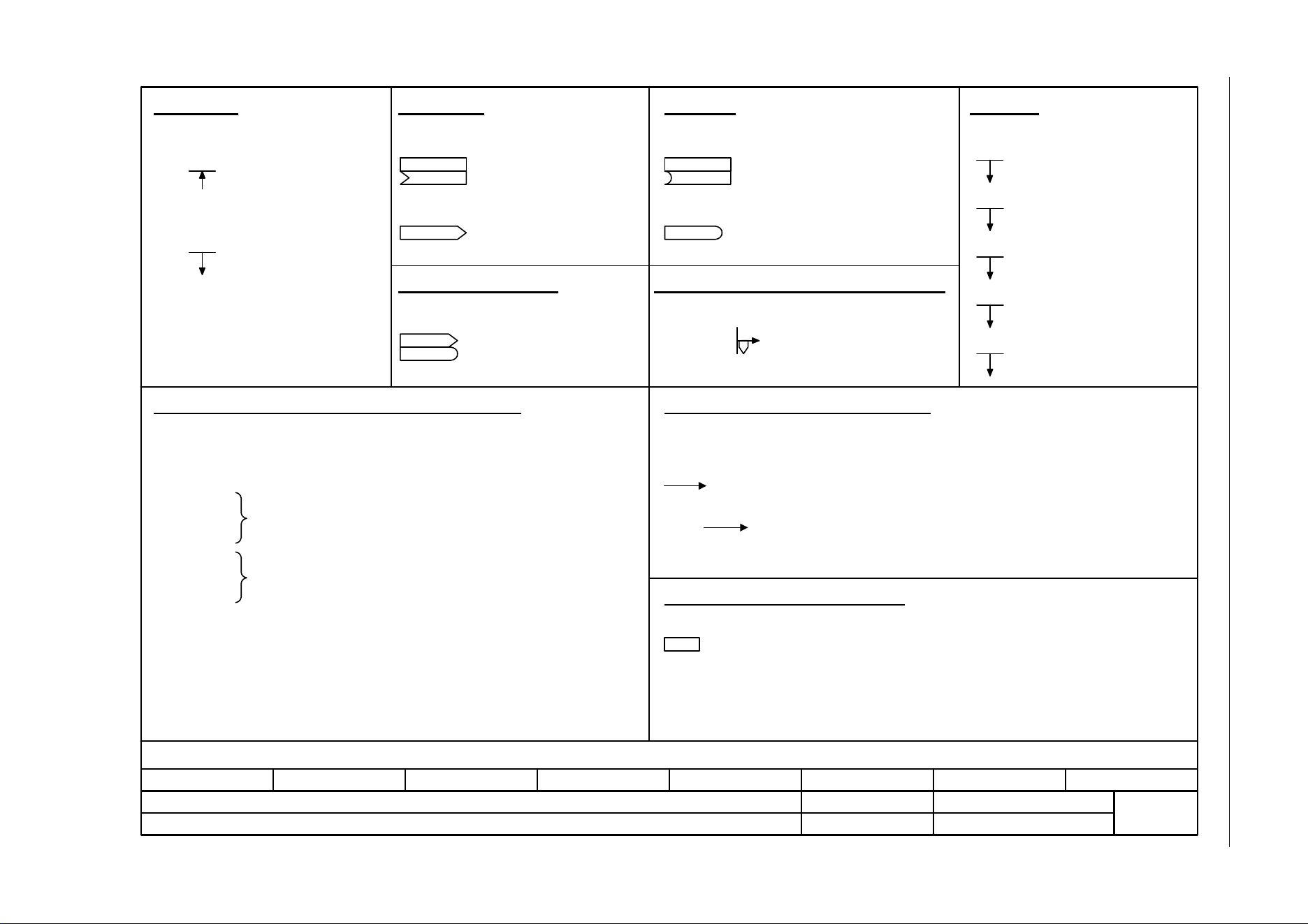
SINAMICS G120C
List Manual (LH13), 04/2014, A5E33840768B AA
323
3 Function diagrams
3.2 Explanation of the function diagrams
Fig. 3-1 1020 – Explanation of the symbols (part 1)
- 1020 -
Function diagram
87654321
fp_1020_97_61.vsd
Explanations on the function diagrams
SINAMICS G120C
07.04.2014 V4.7
Explanation of the symbols (part 1)
(Def)
pxxxx[y..z]
rxxxx[y..z]
(Def.y)
pxxxx[y..z]
rxxxx
rxxxx
rxxxx
[aaaa.b]
[cccc.d]
[aaaa.b]
pxxxx
[aaaa.b]
pxxxx[D]
pxxxx[C] Monitoring parameter with
unit [Unit] and index range
[y..z] or data set [C/D]
Setting parameter with
min/max value and unit
[Unit] data set [C/D] and
factory setting (Def) *)
Connector input CI with
index range [y..z]
or data set [C/D]
and factory setting (Def) *)
Connector output CO with
unit [Unit] and with index
range [y..z]
Binector input BI with with index
range [y..z] or data set [C/D] and
factory setting.bit number (Def)
Binector output BO
Connector/binector output
CO/BO
The function diagrams are sub-divided into signal paths 1...8
in order to facilitate orientation.
Text = Unique signal designation
aaaa = Signal to target diagram aaa
b = Signal to signal path b
Text = Unique signal designation
cccc = Signal from source diagram cccc
d = Signal from signal path d
pxxxx= Original parameter of signal
aaaa = Signal from source diagram aaaa
b = Signal from signal path b
Parameter belongs to the
Command Data Set (CDS).
Parameter belongs to the
Drive Data Set (DDS).
Parameter name
[Unit]
rxxxx[y] or
rxxxx[y...z] or
rxxxx[y].ww or
rxxxx.ww
pxxxx[y] or
pxxxx[y...z] or
pxxxx[y].ww or
pxxxx.ww
from ... to
(xxxx[y].ww)
(Def)
(Def.w)
Parameter name (up to 18 characters)
[dimension unit]
"r" = monitoring parameter. These parameters are read-only
"xxxx" stands for the parameter number
"[y]" specifies the applicable index, "[y…z]" specifies the index range
".ww" specifies the bit number (e.g. 0…15).
"p" = setting parameter. These parameters can be changed.
"xxxx" stands for the parameter number,
"[y]" specifies the applicable index, "[y…z]" specifies the index range ".ww" specifies
the bit number (e.g. 0…15).
Value range.
Parameter number (xxxx) with Index number [y] and bit number .ww.
Factory setting.
Factory setting with bit number as prefix.
Diagram references for setting parameters that occur a multiple number of times.
[Function diagram number, signal path]
Parameters
Symbol Symbol
Symbol
Symbol
Symbol
Meaning Meaning
Meaning
Meaning
Meaning
Connectors Binectors
Connectors/binectors
Cross references between diagrams
Cross references for control bits
Information on parameters, binectors, connectors
Data sets
Parameter name
Parameter name [Unit]
Parameter name
Parameter name
Parameter name
Signal path
To "function diagram name" [aaaa.b] = binectors.
Text
Text
Parameter name [Unit]
rxxxx[y..z]
Parameter name
from ... to [Unit]
pxxxx[C/D] (Def)
Pre-assigned connectors and binectors
Parameter name
from ... to [Unit]
pxxxx[D] (Def)
Setting parameter with min/max
value and unit [Unit] data set [D]
and factory setting (Def)
Symbol Meaning
For some parameters the value for the factory setting is calculated during commissioning for they are dependent on Power Module and motor (see Section 2.1.1 "Calculated").
*)
Symbol Meaning Symbol Meaning
Symbol Meaning
pxxxx[E] Parameter belongs to the
Encoder Data Set (EDS).
pxxxx[M] Parameter belongs to the
Motor Data Set (MDS).
pxxxx[P] Parameter belongs to the
Power unit Data Set (PDS).
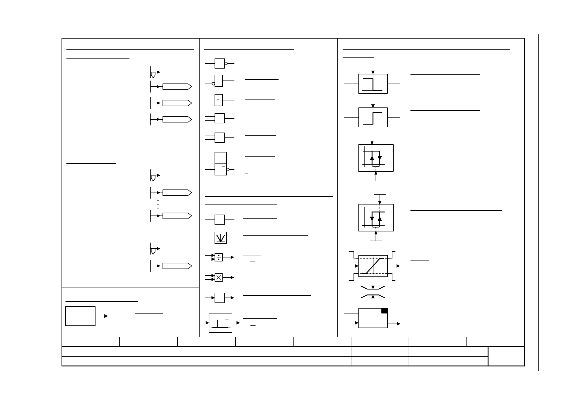
3 Function diagrams
3.2 Explanation of the function diagrams
SINAMICS G120C
324 List Manual (LH13), 04/2014, A5E33840768B AA
Fig. 3-2 1021 – Explanation of the symbols (part 2)
- 1021 -
Function diagram
87654321
fp_1021_97_61.vsd
Explanations on the function diagrams
SINAMICS G120C
07.04.2014 V4.7
Explanation of the symbols (part 2)
y = -x
y = |x|
y =
1
&
x
y
xy
>0
-1
xy
x
2
x
1
y
S Q
R Q
S
y
x
1
0
0
1
y
x
S
y =
LU
LL MLL
MLU
xy
SET
S & H
xyx
y
0
1
S
H
y
x
0
1
H
S
yx
Symbols for logic functions
Logical inversion
AND element
R/S flip-flop
S = setting input
R = reset input
Q = non-inverted output
Q = inverted output
Symbols for computational and closed-loop control
functions
Threshold value switch 1/0
Outputs at y a logical "1" if x < S.
Threshold value switch 0/1
Outputs at y a logical "1" if x > S.
Threshold value 1/0 with hysteresis
Outputs a logical "1" at y if x < S.
If x >= S + H then y returns to 0.
Threshold value 0/1 with hysteresis
Outputs a logical "1" at y if x > S.
If x <= S - H then y returns to 0.
Limiter
x is limited to the upper limit LU and the lower limit LL
and output at y.
The digital signals MLU and MLL have the value "1", if
the upper or lower limit is active.
Sample & Hold element
Sample and hold element.
y = x if SET = 1
(not retentively saved at POWER OFF)
Symbols for computational and closed-
loop control functions
Sign reversal
Absolute value generator
Divider
Comparator greater than 0
y = 1, if the analog signal x > 0, i.e. is
positive.
Differentiator
Symbol for monitoring
Monitoring
Monitoring
Axxxxx
or
Fxxxxx
OR element
Exclusiv-OR/XOR
y = 1 when x1 x2 is.
or
x
1
x
2
1
=1
x
1
y
x
2
dx
dt
p2900[D]
p2901[D]
-10 000.00...10 000.00 [%]
p2900[D] (0.00)
-10 000.00...10 000.00 [%]
p2901[D] (0.00)
-210 000.000...210 000.000 [1/min]
p1001[D] (0.000)
p1001[D]
-210 000.000...210 000.000 [1/min]
p1015[D] (0.000)
p1015[D]
-100 000.00...100 000.00 [Nm]
p2930[D] (0.00)
p2930[D]
r2902[0...14]
[%]
p2902[0...14] (0.00)
p2902[0] = +0 %
p2902[1] = +5 %
p2902[2] = +10 %
p2902[3] = +20 %
p2902[4] = +50 %
p2902[5] = +100 %
p2902[6] = +150 %
p2902[7] = +200 %
p2902[8] = -5 %
p2902[9] = -10 %
p2902[10] = -20 %
p2902[11] = -50 %
p2902[12] = -100 %
p2902[13] = -150 %
p2902[14] = -200 %
d
dt
Pre-assigned connectors and binectors
Fixed speed values
Fixed torque value
n_set_fixed 1
-210000.000 ... 210000.000 [rpm]
p1001 [D] (0.000)
Fixed value 1 [%]
-10000.00 ... 10000.00 [%]
p2900 [D] (0.00)
Fixed value M [Nm]
-100000.00 ... 100000.00 [Nm]
p2930 [D] (0.00)
or
or
Fixed percentage values
or
Fixed value
2 [%]
Fixed value 1 [%]
n_set_fixed 1
n_set_fixed 15
Fixed value
M [Nm]
y = x
1
•x
2
x
2
x
1
y
Multiplier
Comparator
=
x
1
y
x
2
y = 1 when x1 = x2 is.
with logical inversion of an input signal
Fixed values
In the bottom right-hand
corner of the diagram.
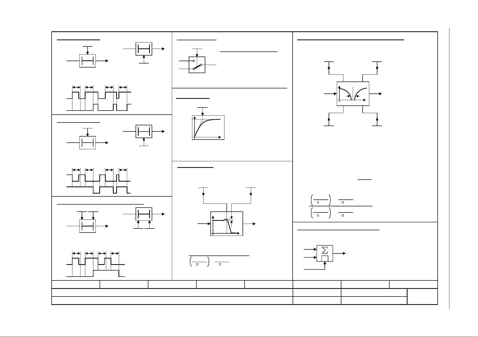
SINAMICS G120C
List Manual (LH13), 04/2014, A5E33840768B AA
325
3 Function diagrams
3.2 Explanation of the function diagrams
Fig. 3-3 1022 – Explanation of the symbols (part 3)
- 1022 -
Function diagram
87654321
fp_1022_97_61.vsd
Explanations on the function diagrams
SINAMICS G120C
07.04.2014 V4.7
Explanation of the symbols (part 3)
T0xy
pxxxx
yx
H(s) =
s
2
2
• s + 1
+
+
s
2
2
2 •
2
2
f
2nd Order Filter
|y|
fs
f_B
t
y
pxxxx
H(s) =
+
s
• s
+1
2 •
2
1
yx
f
|y|
fn
D
0Txy
pxxxx
T1 T2
T0
pxxxx
0T
pxxxx
xy
xy
xy
T1 T2
xy
pxxxx pxxxx
pxxxx pxxxx
x
T
y
x
y
x
T
y
T1 T1 T2 T2
y
x
1
I
x
2
f_B
Switch-on delay
The digital signal x must have the value "1" without any interruption
during the time T before output y changes to "1".
Switch-off delay
The digital signal x must have the value "0" without interruption
during the time T before output y changes to "0".
Delay (switch-on and switch-off)
PT1 element
Delay element, first order.
pxxxx = time constant
PT2 low pass
Damping, denominator
D_d
pxxxx
Natural frequency, denominator
fn_d
pxxxx
Damping, denominator
D_d
pxxxx
Natural frequency, denominator
fn_d
pxxxx
Transfer function
2nd-order filter (bandstop/general filter)
Natural frequency, numerator
fn_n
pxxxx
Damping, numerator
D_n
pxxxx
Used as bandstop filter
- center frequency fs: fn_n = fs
fn_d = fs
- bandwidth f_B: D_n = 0
D_d =
Transfer function when used as general filter
Analog adder can be activated
The following applies to I = 1 signal: y = x1 + x2
The following applies to I = 0 signal: y = x1
The digital signal x must have the value "1" without interruption
during time T1 or must have the value "0" during time T2 before
output y changes its signal state.
2 •
• s + 1
2 • fs
TTT
TTT
1
0
pxxxx
Switch symbol
Simple changeover switch
The switch position is shown according
to the factory setting
(in this case, switch position 1 in the
default state on delivery).
fn_n
D_n
D_d
fn_d
fn_n
fn_d
D_d
2
fn_d
2
fn_d
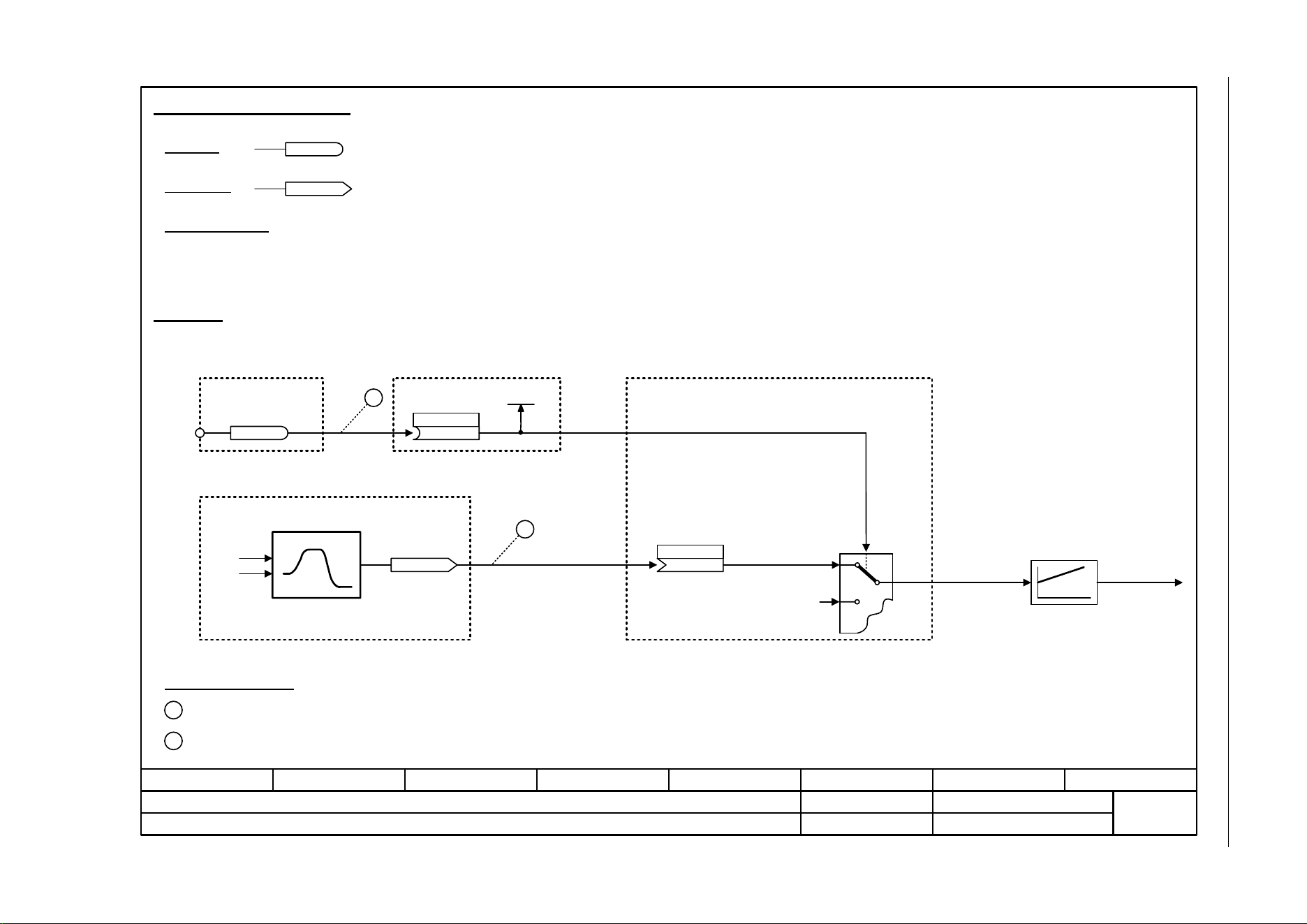
3 Function diagrams
3.2 Explanation of the function diagrams
SINAMICS G120C
326 List Manual (LH13), 04/2014, A5E33840768B AA
Fig. 3-4 1030 – Handling BICO technology
- 1030 -
Function diagram
87654321
fp_1030_97_61.vsd
Explanations on the function diagrams
SINAMICS G120C
07.04.2014 V4.7
Handling BICO technology
r0723.15
r0723
r0722.0
1
2
722.0
p1055[C]
Kl. 5
r0967.8
[2220] [2501]
[3020]
r1050
[3030]
2
1
p1055[0] = 722.0
p1070[0] = 1050
Main setpoint
(755[0])
p1070[C]
Handling BICO technology
Binector:
Connector:
Raise
Connectors are "analog signals" that can be freely interconnected (e.g. percentage variables, speeds or torques).
Connectors are also "CO:" display parameters (CO = Connector Output).
Parameterization:
At the signal destination, the required binector or connector is selected using appropriate parameters:
"BI:" parameter for binectors (BI = Binector Input)
or
"CI:" parameter for connectors (CI = Connector Input)
Example:
The main setpoint for the speed controller (CI: p1070) should be received from the output of the motorized potentiometer
(CO: r1050) and the "jog" command (BI: p1055) from Digital Input DI 0 (BO: r0722.0, Terminal 5 (Kl. 5)) on the CU.
Control bit 8
Digital Input DI0
Setpoint
channel
Motorized potentiometer
Jog setpoint 1
Speed controller
Parameterizing steps:
Terminal 5 (Kl. 5) acts as "Jog bit 0".
The output of the motorized potentiometer acts as main setpoint for the speed controller.
Lower
(1050)
Binectors are binary signals that can be freely interconnected (BO = Binector Output).
They represent a bit of a "BO:" display parameter (e.g. bit 15 from r0723).

SINAMICS G120C
List Manual (LH13), 04/2014, A5E33840768B AA
327
3 Function diagrams
3.3 Input/output terminals
3.3 Input/output terminals
Function diagrams
2201 – Connection overview 328
2221 – Digital inputs, electrically isolated (DI 0 ... DI 5) 329
2241 – Digital outputs (DO 0 ... DO 1) 330
2250 – Analog input 0 (AI 0) 331
2255 – Analog inputs as digital inputs (DI 11) 332
2260 – Analog output 0 (AO 0) 333
2272 – Two-wire control 334
2273 – Three-wire control 335
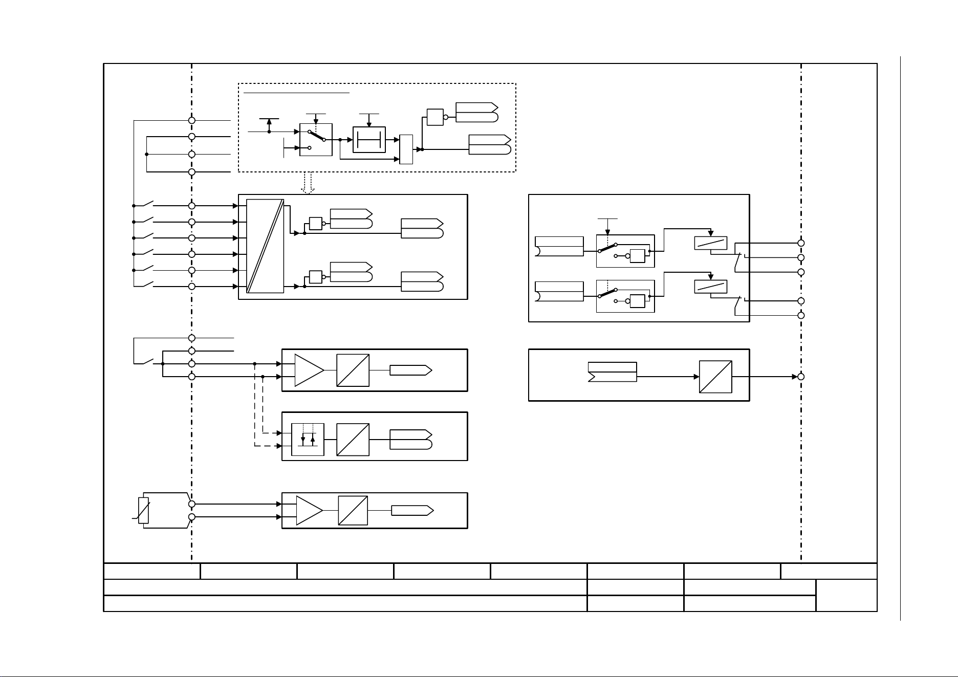
3 Function diagrams
3.3 Input/output terminals
SINAMICS G120C
328 List Manual (LH13), 04/2014, A5E33840768B AA
Fig. 3-5 2201 – Connection overview
- 2201 -
Function diagram
87654321
fp_2201_97_05.vsd
Input/Output Terminals
SINAMICS G120C
07.04.2014 V4.7
Connection overview
Simulation for DI 0 ... DI 5, DI 11
Kl. 5
Kl. 6
DI 0
DI 1
CU DI status
r0722
r0722
1
0
1
r0721
p0796
CU DI status inv
r0723
r0723
CU DI status
r0722
r0722
CU DI simulation
p0795
1 = Simulation on
T0
2 Digital outputs
[2221]
DO 1
(52.7)
CU S_src DO 1
p0731
(52.3)
CU S_src DO 0
p0730
6 Digital inputs
[2241]
Kl. 7
Kl. 8
DI 3+
DI 2
Kl. 16
Kl. 17
DI 5+
DI 4
Kl. 4
Kl. 3
1 Analog input[2250]
A
D
r0755
CU AI value in % [%]
CU DI status inv
r0723
r0723
1
CU DI status
r0722
r0722
CU DI status inv
r0723
r0723
1
...
.0
.0
.5
.5
Analog output[2260]
D
A
CU AO S_src
(21[0])
p0771
AO 0
NO
COM
NC
Kl. 20
Kl. 19
Kl. 18
DO 0
Kl. 21
Kl. 22
NO
COM
Kl. 12
&
AI 0+
AI 0-
+24 V OUTKl. 9
Kl. 28
Kl. 69
Kl. 34
GND
DI COM1
DI COM2
+10 V OUTKl. 1
Kl. 2
GND
24 V
5 V
CU DI t_debounce
p0724
.0...11
.0...11
.0...11
.0...11
.0...11
[0]
...
[2255] Analog inpust as Digital input
A
D
0
1
1.6 V 4.0 V
CU DI status
r0722
r0722
.11
Kl. = Terminal
Kl. 14
Kl. 15
T1 MOTOR
T2 MOTOR
A
D
r0035
Mot temp [°C]
[2]
[8016] Thermal monitoring, motor
1
0
1
1
0
1
CU DO inv
p0748
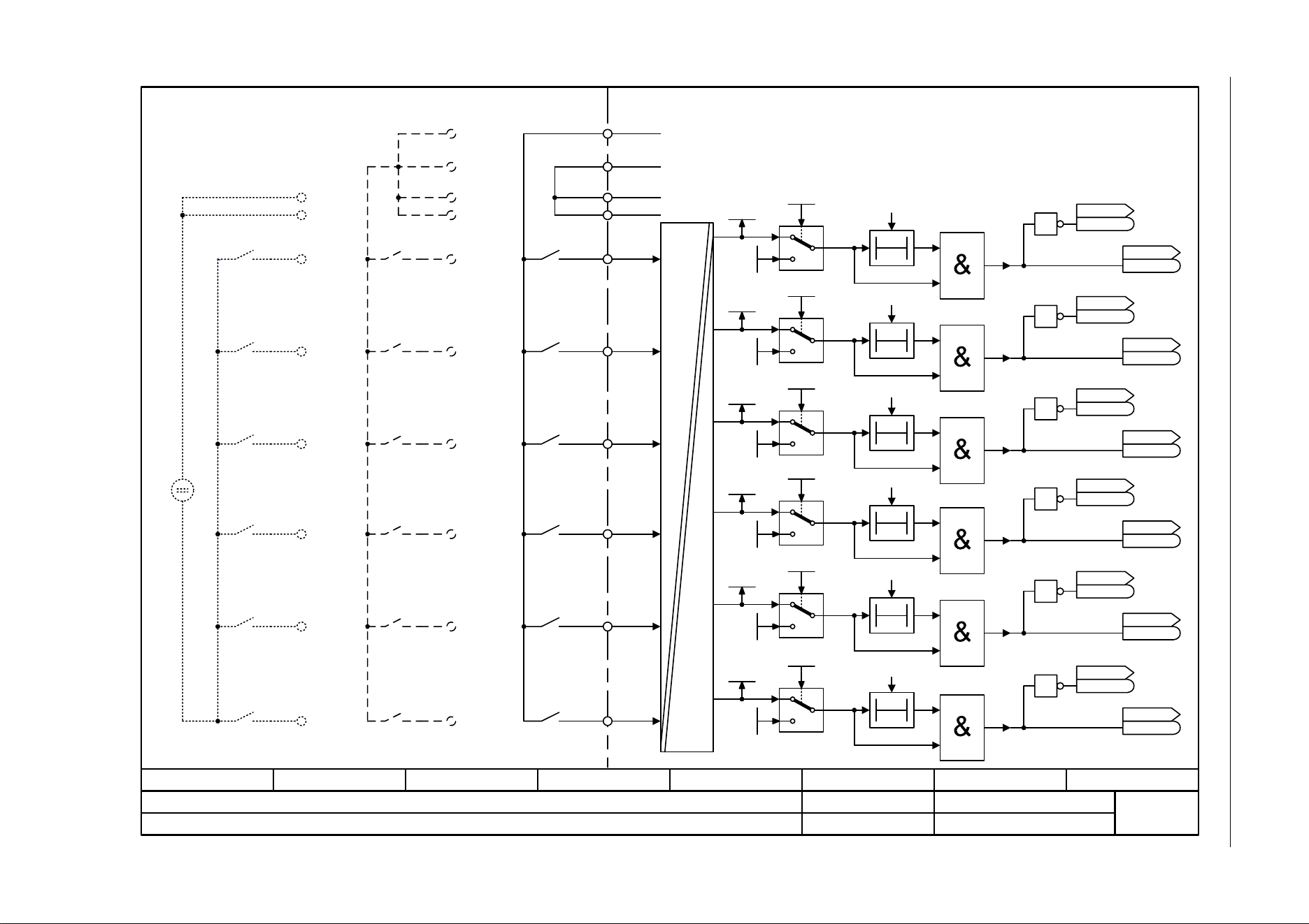
SINAMICS G120C
List Manual (LH13), 04/2014, A5E33840768B AA
329
3 Function diagrams
3.3 Input/output terminals
Fig. 3-6 2221 – Digital inputs, electrically isolated (DI 0 ... DI 5)
- 2221 -
Function diagram
87654321
fp_2221_97_05.vsd
Input/Output Terminals
SINAMICS G120C
07.04.2014 V4.7
Digital inputs, electrically isolated (DI 0 … DI 5)
+24 V OUTKl. 9
Kl. 5
Kl. 6
Kl. 7
Kl. 17
p0795.1
p0795.2
p0795.5
Kl. 28 GND
24 V
5 V
1
0
1
0
1
0
1
0
1
1
1
1
DI 5
DI 2
DI 1
DI 0
r0721.0
r0721.1
r0721.2
r0721.5
p0796.5
p0796.2
p0796.1
p0796.0
Kl. = Terminal
CU DI status inv
r0723
r0723
CU DI status
r0722
r0722
Kl. 8
p0795.3
1
0
1
DI 3
r0721.3
p0796.3
Kl. 16
p0795.4
1
0
1
DI 4
r0721.4
p0796.4
CU DI simulation
p0795
1 = Simulation on
.0
.0
CU DI status inv
r0723
r0723
CU DI status
r0722
r0722
.1
.1
CU DI status inv
r0723
r0723
CU DI status
r0722
r0722
.2
.2
CU DI status inv
r0723
r0723
CU DI status
r0722
r0722
.3
.3
CU DI status inv
r0723
r0723
CU DI status
r0722
r0722
.4
.4
CU DI status inv
r0723
r0723
CU DI status
r0722
r0722
.5
.5
T0
T0
T0
T0
T0
T0
.0
External power supply
24 V DC
Kl. 69 DI COM
PNP
Kl. 9
Kl. 5
Kl. 6
Kl. 7
Kl. 17
Kl. 28 GND
DI 5
DI 2
DI 1
DI 0
Kl. 8
DI 3
Kl. 16
DI 4
Kl. 69
NPN
+24 V OUT
DI COM
Kl. 5
Kl. 6
Kl. 7
Kl. 17 DI 5
DI 2
DI 1
DI 0
Kl. 8
DI 3
Kl. 16
DI 4
Kl. 69 DI COM
or
Sampling time of the DI: 2 ms
Kl. 34 DI COM2Kl. 34 DI COM2Kl. 34 DI COM2
4.0 [ms]
4.0 [ms]
4.0 [ms]
4.0 [ms]
4.0 [ms]
4.0 [ms]
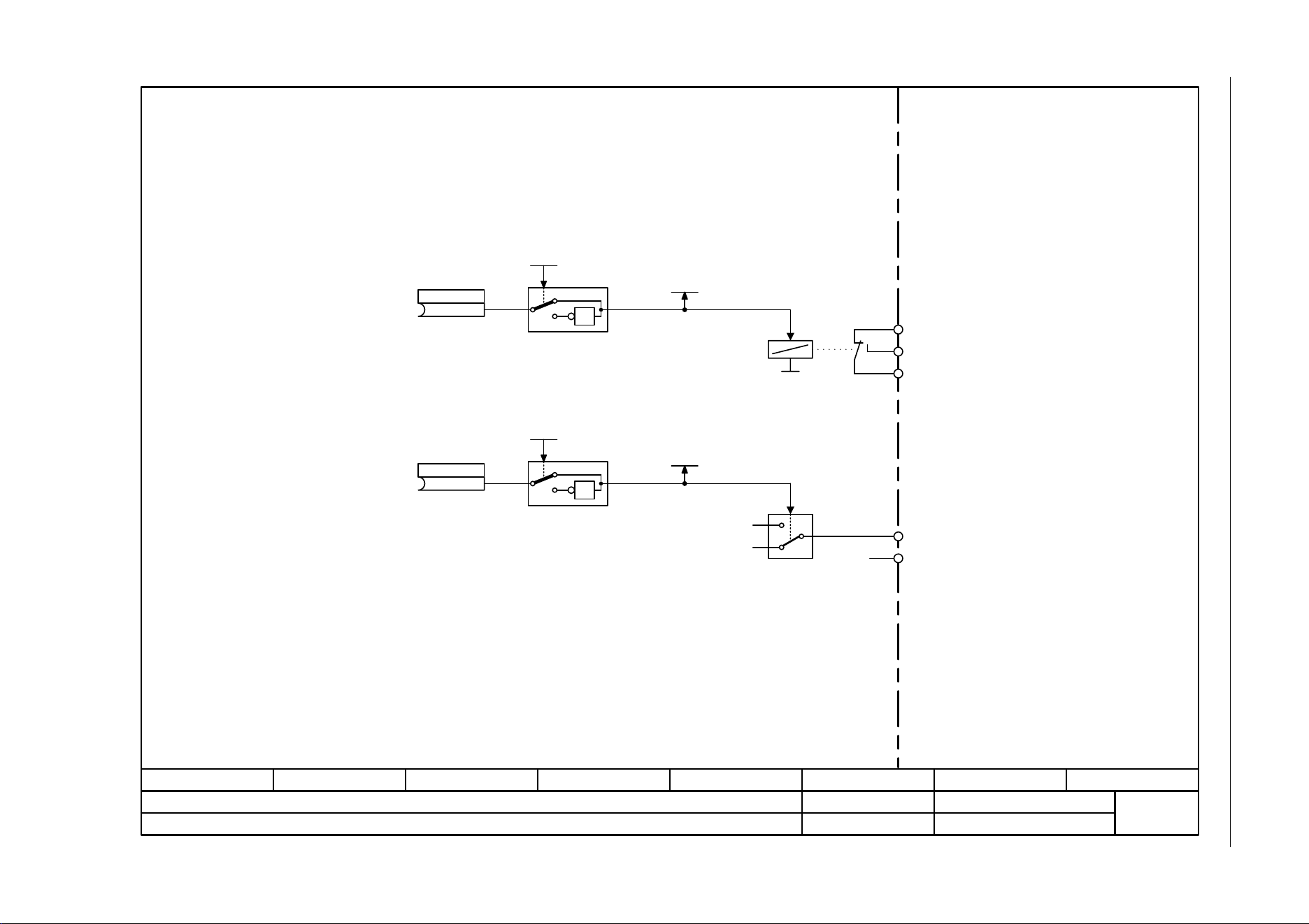
3 Function diagrams
3.3 Input/output terminals
SINAMICS G120C
330 List Manual (LH13), 04/2014, A5E33840768B AA
Fig. 3-7 2241 – Digital outputs (DO 0 ... DO 1)
- 2241 -
Function diagram
87654321
fp_2241_97_05.vsd
Input/Output Terminals
SINAMICS G120C
07.04.2014 V4.7
Digital outputs (DO 0 … DO 1)
(52.3)
CU S_src DO 0
p0730
(52.7)
CU S_src DO 1
p0731
CU DO inv
p0748
CU DO inv
p0748
NO
COM
NC
Kl.20
Kl.19
Kl.18
NO
Kl.22
Kl.21
DO 0
DO 1
Kl. = Terminal
Sampling time of the DO: 2 ms
CU DO status
r0747
CU DO status
r0747
.1
.0
1
0
24 V
0 V
0 V
1
0
1
1
0
1
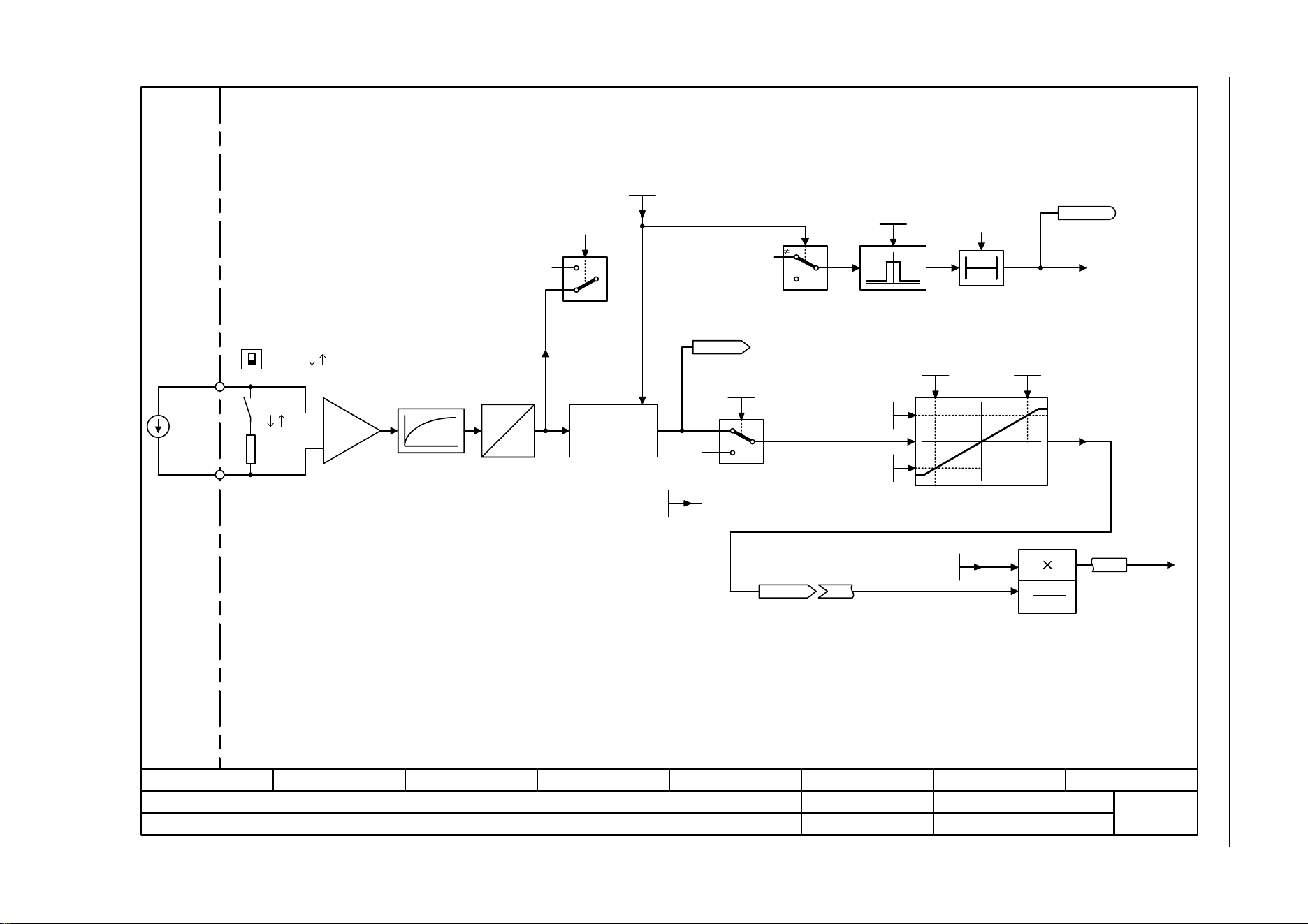
SINAMICS G120C
List Manual (LH13), 04/2014, A5E33840768B AA
331
3 Function diagrams
3.3 Input/output terminals
Fig. 3-8 2250 – Analog input 0 (AI 0)
- 2250 -
Function diagram
87654321
fp_2250_97_05.vsd
Input/Output Terminals
SINAMICS G120C
07.04.2014 V4.7
Analog input 0 (AI 0)
3
3
20 mA
T0
<2>
0 … 20 mA
-10 … +10 V
Kl.3
[%]
xy
<2> <2>
A
D
+
-
<1>
<1>
x
1
y
2
x
2
y
1
y
x
[%]
y
x
2
x
1
<2>
<3>
% 100
xx
21
•
<3>
I
1
0
20 mA
1
0
Voltage
Current
Hardware smoothing
100 µs
Scaling
Differential Input!
For an input signal referred to ground, terminal 4 must be connected to reference potential M.
Caution:
The voltage between an input (Kl. 3 (Kl. 10) or Kl. 4 (Kl. 11)) and the ground point must not exceed 35 V.
When the load resistor is switched in (DIP switch in position ĹI), the voltage between the input terminals
must not exceed 10 V or the impressed current 80 mA.
For p0756 = 2, 3 the units are mA.
For p0756 = 0, 1, 4 the units are V.
F03505
"Wire
breakage"
r0752
CU AI U/I_inp act
Kl.4
Kl. = Terminal
Sampling time of the AI: 4 ms
r0755
CU AI value in % [%]
[0]
<2>
<2>
Type switching
Analog input
U I
U
AI 0
U I
AI 0
CU AI status word
r0751
CU WireBrkThresh
0.00 ... 20.00
p0761[0..1] (2.00)
CU AI sim_mode
0 ... 1
p0797[0..1] (0)
CU AI sim setp
-50.000 ... 2000.000
p0798[0..1] (0.000)
CU AI char y1
-1000.00 ... 1000.00 [%]
p0758[0..1] (0.00)
CU AI char y2
-1000.00 ... 1000.00 [%]
p0760[0..1] (100.00)
CU AI char x1
-50.000 ... 160.000
p0757[0..1] (0.000)
CU AI char x2
-50.000 ... 160.000
p0759[0..1] (10.000)
CU AI type
0... 8
p0756[0..1] (4)
CU AI sim_mode
0 ... 1
p0797[0..1] (0)
[0] (0.000)
[0] (0)
[0] (0.00)
[0] (0)
[0] (4)
[0] (2.00)
100 [ms]
[0] (100.00)
[0] (0.000) [0] (10.000)
Wire breakage sensing only activated when p0756 = 1, 3.
Reference quantities
p2000 … r2004
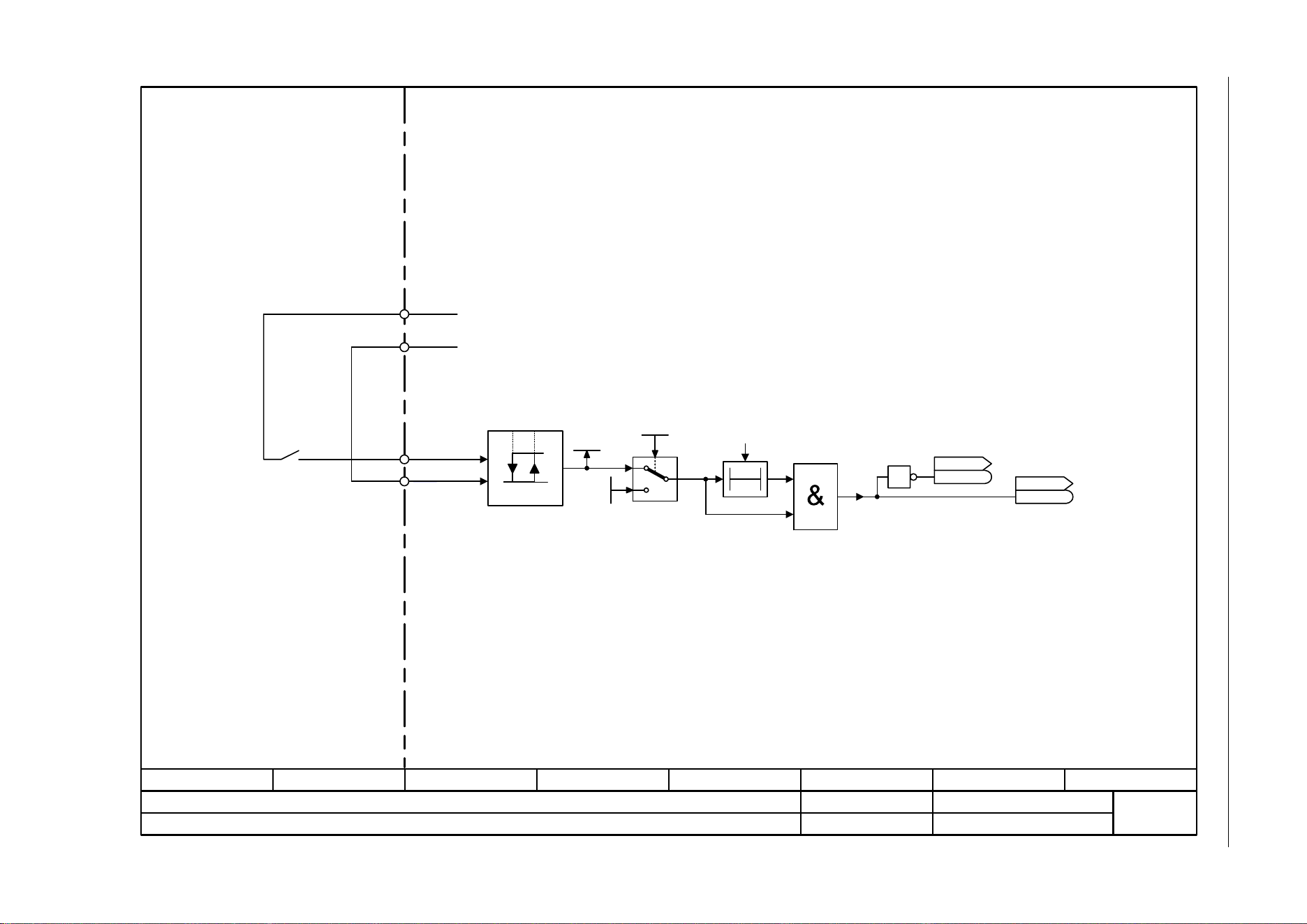
3 Function diagrams
3.3 Input/output terminals
SINAMICS G120C
332 List Manual (LH13), 04/2014, A5E33840768B AA
Fig. 3-9 2255 – Analog inputs as digital inputs (DI 11)
- 2255 -
Function diagram
87654321
fp_2255_97_05.vsd
Input/Output Terminals
SINAMICS G120C
07.04.2014 V4.7
Analog inputs as Digital input (DI 11)
1
0
1
r0721.11
p0796.11
CU DI status inv
r0723
r0723
CU DI status
r0722
r0722
CU DI simulation
p0795
1 = Simulation on
.11
.11
T0
1.6 V 4.0 V
Kl. = Terminal
Kl.3
AI 0+ (DI 11)
Kl.4
+10 V OUT
Kl.1
Kl.2 GND
For Example:
Sampling time of the DI: 4 ms
AI 0-
0
1
.11
4.0 [ms]
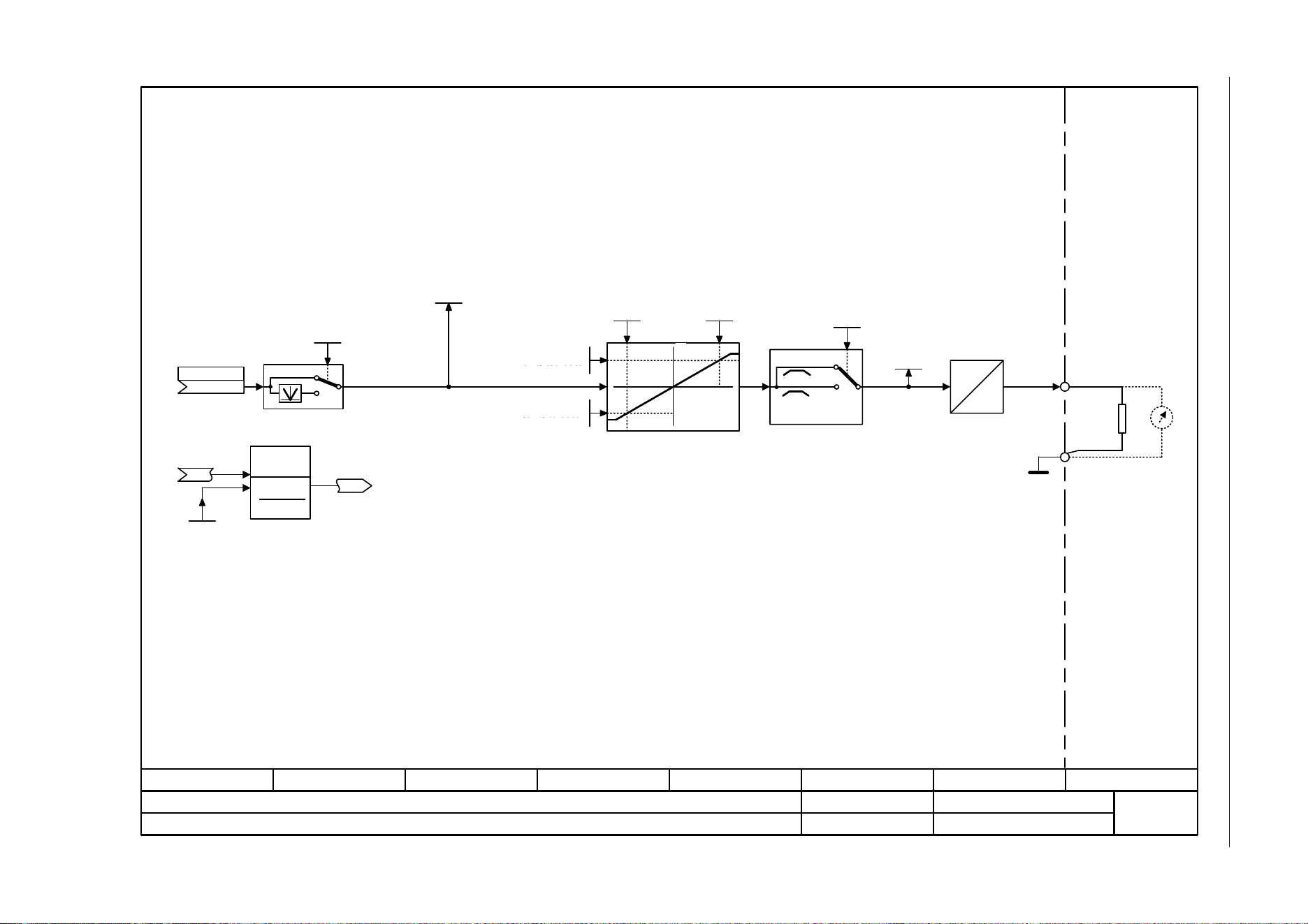
SINAMICS G120C
List Manual (LH13), 04/2014, A5E33840768B AA
333
3 Function diagrams
3.3 Input/output terminals
Fig. 3-10 2260 – Analog output 0 (AO 0)
- 2260 -
Function diagram
87654321
fp_2260_97_05.vsd
Input/Output Terminals
SINAMICS G120C
07.04.2014 V4.7
Analog output 0 (AO 0)
Kl.12
Kl.13
D
A
xy
y
<1>
<1>
<2>
<3>
0 … 10 V
0 … 20 mA
x
1
y
2
x
2
y
1
y
x
[%]
<1>
<2>
<3>
y
x
2
x
1
[%]
2
1
x
% 100x •
%
0
1
AO 0+
2
0, 1
4 mA
0
Scaling
Voltage output
Current
output
For p0776 = 0, 2 the units are mA.
For p0776 = 1 the units are V.
The input signals are referred to the reference quantities p2000 ... r2004 (100 % = p200x).
Possible settings p0776[0]:
= 0: 0 ... +20 mA
= 1: 0 ... +10 V
= 2: 4 ... +20 mA
Reference
quantities
p2000 … r2004
CU AO absVal act
0 ... 1
p0775 (0)
CU AO S_src
(21[0])
p0771
CU AO char x1
-1000.00 ... 1000.00 [%]
p0777 (0.00)
CU AO char x2
-1000.00 ... 1000.00 [%]
p0779 (100.00)
CU AO type
0 ... 2
p0776 (0)
CU AO U/I_outp
r0774
Sampling time of the AO: 4 ms Kl. = Terminal
GND
<1>
CU AO outp act ref [%]
r0772
[0]
[0] (0)
[0]
[0] (0) [0] (100)
[0] (0)
[0]
CU AO char y1
-20.000 ... 20.000 [V]
p0778[0..1] (0.000)[0] (0)
CU AO char y2
-20.000 ... 20.000 [V]
p0780[0..1] (20.000)
[0] (20)
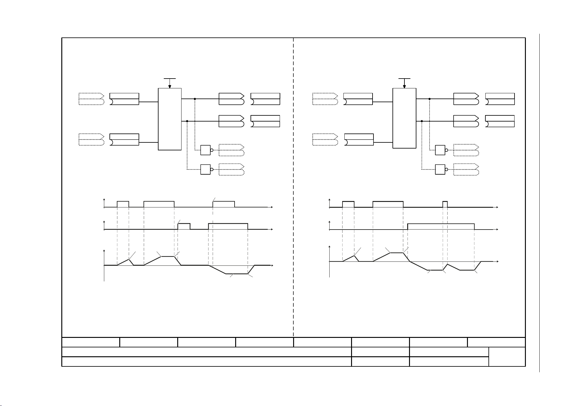
3 Function diagrams
3.3 Input/output terminals
SINAMICS G120C
334 List Manual (LH13), 04/2014, A5E33840768B AA
Fig. 3-11 2272 – Two-wire control
- 2272 -
Function diagram
87654321
fp_2272_97_62.vsd
Input/Output Terminals
SINAMICS G120C
07.04.2014 V4.7
Two-wire control
(0)
2/3 wire cmd 1
p3330[C]
0 ... 4
p3334 (0)
CU DI status
r0722
r0722
.x
CU DI status
r0722
r0722
.x
0 ... 4
p3334 (0)
CU DI status
r0722
r0722
.x
CU DI status
r0722
r0722
.x
t
t
t
AUS1
t
t
t
1
1
<1>
1
1
OFF1
OFF1
Setpoint inverted
Setpoint inverted
Setpoint
Setpoint
Command ignored
Clockwise
Counterclockwise
Motor speed
Clockwise
Counterclockwise
Motor speed
OFF1
OFF1
Command ignored
OFF1
OFF1
Counterclockwise
ON / OFF1
Clockwise
ON / OFF1
Counterclockwise
ON / OFF1
Clockwise
ON / OFF1
Ongoing interconnection is either possible from r3333.0/r3333.1 or from the inverted signals r3333.2/r3333.3.
Two-wire control (p0015 = 17 or p3334 = 1)
clockwise/counterclockwise 1
Two-wire control (p0015 = 18 or p3334 = 2)
clockwise/counterclockwise 2
(0)
2/3 wire cmd 2
p3331[C]
(0)
2/3 wire cmd 1
p3330[C]
(0)
2/3 wire cmd 2
p3331[C]
2/3 wire STW
r3333
r3333
2/3 wire STW
r3333
r3333
.0
.1
(722.1)
Setp inv
p1113[C]
(722.0)
ON / OFF (OFF1)
p0840[C]
<1>
2/3 wire STW
r3333
r3333
.2
2/3 wire STW
r3333
r3333
.3
2/3 wire STW
r3333
r3333
2/3 wire STW
r3333
r3333
.0
.1
(722.1)
Setp inv
p1113[C]
(722.0)
ON / OFF (OFF1)
p0840[C]
<1>
2/3 wire STW
r3333
r3333
.2
2/3 wire STW
r3333
r3333
.3
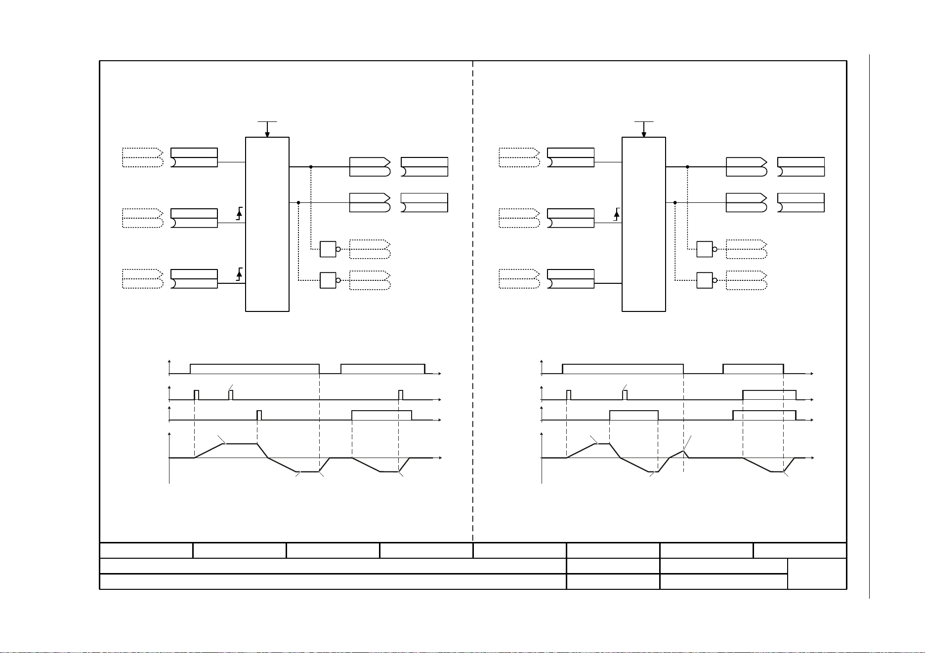
SINAMICS G120C
List Manual (LH13), 04/2014, A5E33840768B AA
335
3 Function diagrams
3.3 Input/output terminals
Fig. 3-12 2273 – Three-wire control
- 2273 -
Function diagram
87654321
fp_2273_97_62.vsd
Input/Output Terminals
SINAMICS G120C
07.04.2014 V4.7
Three-wire control
(0)
2/3 wire cmd 1
p3330[C]
0 ... 4
p3334 (0)
(0)
2/3 wire cmd 2
p3331[C]
(0)
2/3 wire cmd 3
p3332[C]
(0)
2/3 wire cmd 1
p3330[C]
0 ... 4
p3334 (0)
(0)
2/3 wire cmd 2
p3331[C]
(0)
2/3 wire cmd 3
p3332[C]
t
t
t
t
t
t
t
t
2/3 wire STW
r3333
r3333
2/3 wire STW
r3333
r3333
.0
.1
(722.1)
Setp inv
p1113[C]
(722.0)
ON / OFF (OFF1)
p0840[C]
2/3 wire STW
r3333
r3333
2/3 wire STW
r3333
r3333
.0
.1
(722.1)
Setp inv
p1113[C]
(722.0)
ON / OFF (OFF1)
p0840[C]
<1>
1
2/3 wire STW
r3333
r3333
.2
1
2/3 wire STW
r3333
r3333
.3
<1>
1
2/3 wire STW
r3333
r3333
.2
1
2/3 wire STW
r3333
r3333
.3
<1>
OFF1 OFF1
OFF1
OFF1Setpoint inverted Setpoint inverted
Setpoint Setpoint
Command ignored Command ignored
Enable /
OFF1
ON
Clockwise
ON
Counterclockwise
Clockwise
Counterclockwise
Motor speed
ON
Clockwise
Counterclockwise
Motor speed
Reversing
Enable /
OFF1
Ongoing interconnection is either possible from r3333.0/r3333.1 or from the inverted signals r3333.2/r3333.3.
Three-wire control (p0015 = 19 or p3334 = 3)
enable clockwise/counterclockwise
Three-wire control (p0015 = 20 or p3334 = 4)
enable ON/reversing
CU DI Status
r0722
r0722
.x
CU DI status
r0722
r0722
.x
CU DI Status
r0722
r0722
.x
CU DI Status
r0722
r0722
.x
CU DI status
r0722
r0722
.x
CU DI Status
r0722
r0722
.x

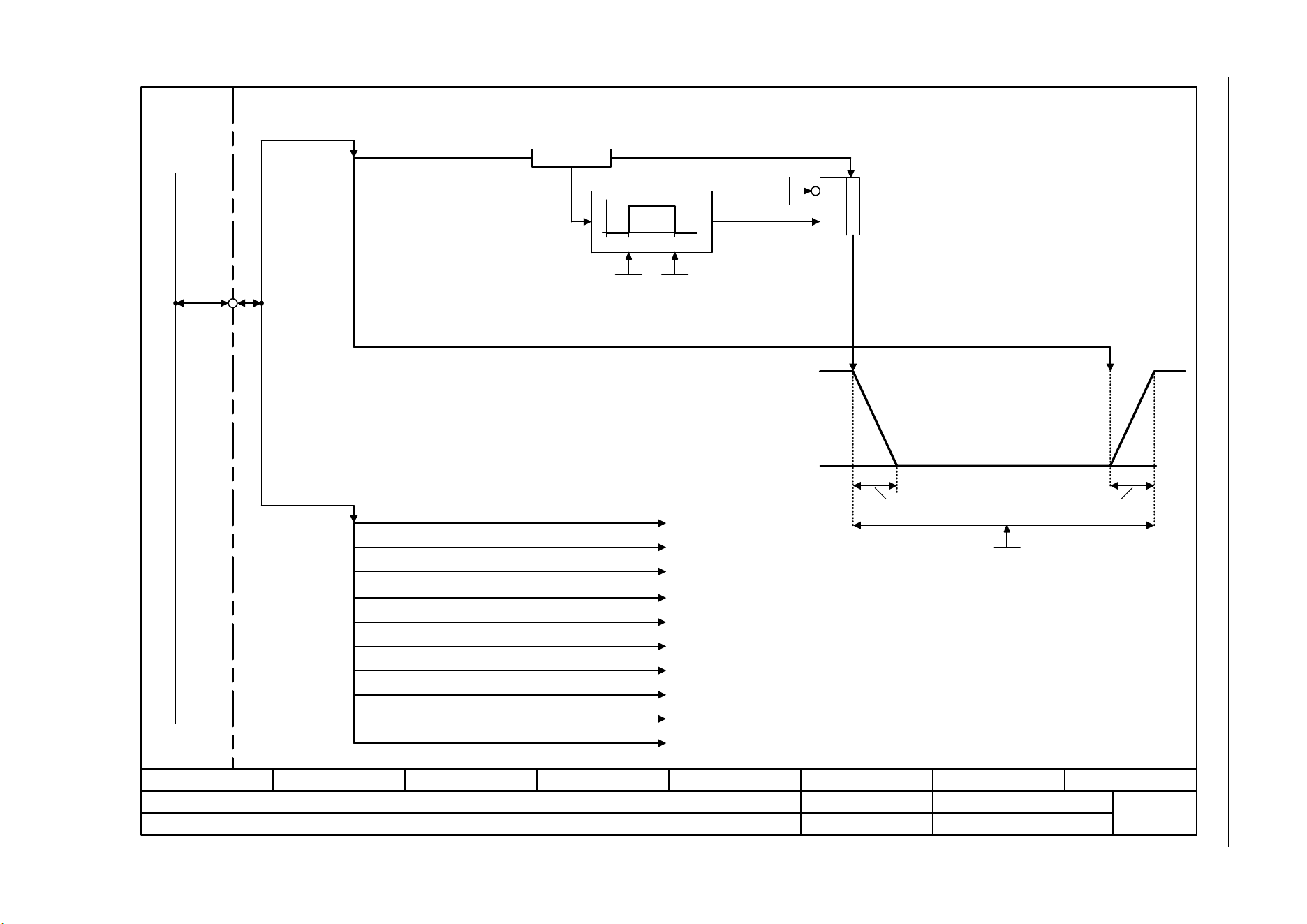
SINAMICS G120C
List Manual (LH13), 04/2014, A5E33840768B AA
337
3 Function diagrams
3.4 PROFIenergy
Fig. 3-13 2381 – Control commands and interrogation commands
- 2381 -
Function diagram
87654321
fp_2381_97_62.vsd
PROFIenergy
SINAMICS G120C PN
07.04.2014 V4.7
Control commands and interrogation commands
PROFINET
Port 1
Port 2
PROFIenergy
interrogation commands
[2382]
PROFIenergy
control commands
"Start_Pause_with_time_response"
"End_Pause"
"List_Energy_Saving_Modes“
"Get_Mode“
"PEM_Status“
"PE_Identify“
"Query_Version“
"Get_Measurement_List“
"Get_Measurement_Values“
"Get_Measurement_Values_with_object_number“
"Get_Measurement_List_with_object_number“
"PEM_Status_with_CTTO“
Pe mod t_pause min
p5602
p5611.0
Ready for operation
r5600 = 255
r5600 = 2
Energy-saving mode 2
1 = Inhibit
PROFIenergy
Pause_Time
&
Time_to_pause Time_to_operate
1
0
min max
p5606
+ Time_to_pause
+ Time_to_operate
p5602
"Start_Pause"
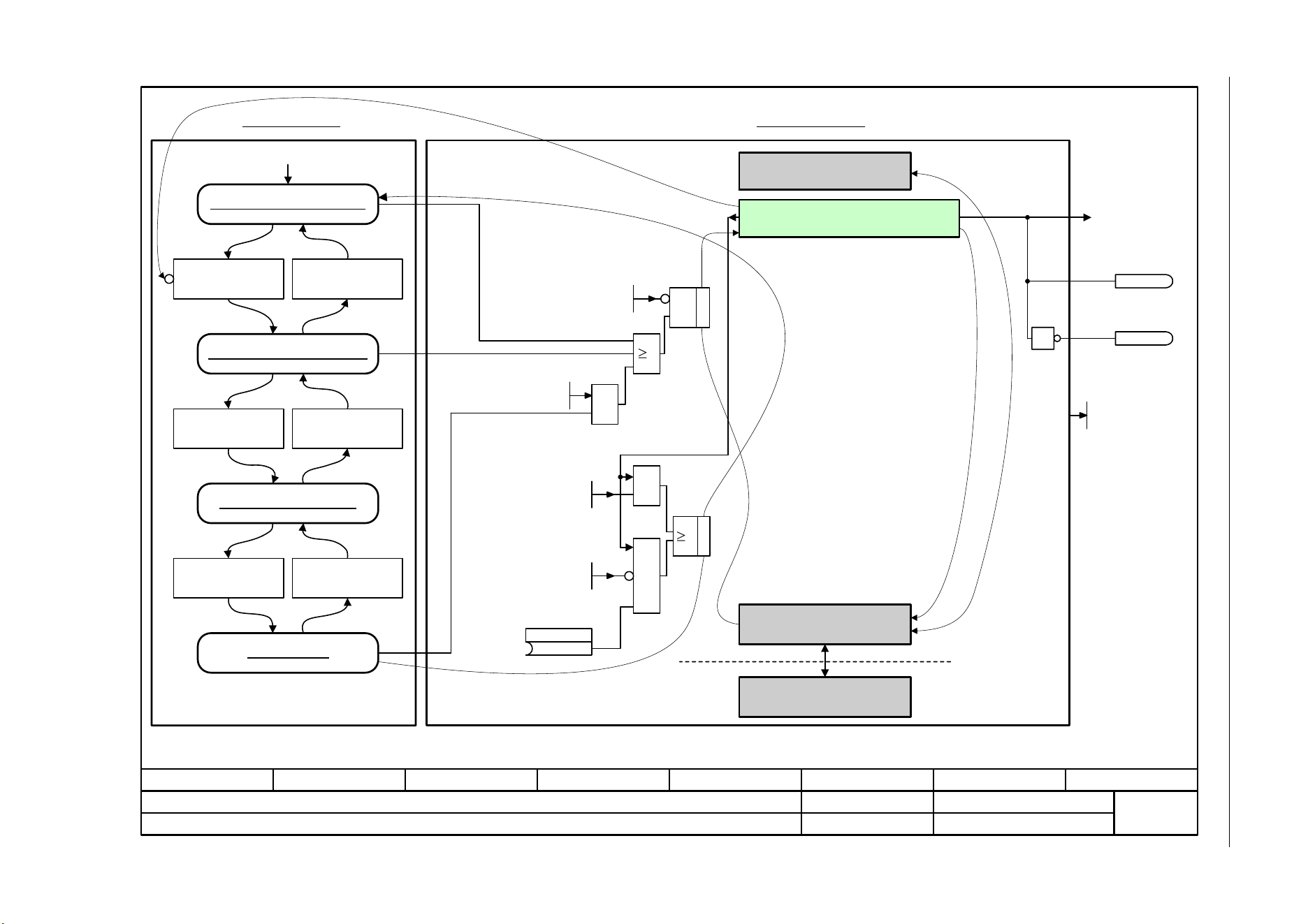
3 Function diagrams
3.4 PROFIenergy
SINAMICS G120C
338 List Manual (LH13), 04/2014, A5E33840768B AA
Fig. 3-14 2382 – States
- 2382 -
Function diagram
87654321
fp_2382_97_62.vsd
PROFIenergy
SINAMICS G120C PN
07.04.2014 V4.7
States
PROFIdrive State
(0)
Pe sw on_inh s_src
p5614
&
&
&
p5611
1 = Inhibit PROFIenergy
.0
p5611
1 = Drive initiates OFF1
.1
p5611.2
1 = Trans into energy-saving
mode from PROFIdrive
state S4 possible
p5611.1
1 = Drive initiates OFF1
1
PROFIenergy Ready for
operation
r5613.0
1
A08800
PROFIenergy State
r5613.1
1 = PE active
1 = PE inactive
PROFIenergy Energy-
saving mode active
PROFIenergy Power OFF
Pe mode ID
r5600
PROFIenergy Energy-saving mode 2
POWER ON
S1: Switching on inhibited
S2: Ready for switching on
S3:Ready for operation
S4: Operation
<1>
Excerpt from: Basic state machine of a PROFIdrive drive axis,
source: PROFIBUS Nutzerorganisation (PNO)
<1>
OFF
and no "Coast Stop"
and no "Quick Stop"
"Coast Stop"
or "Quick Stop"
OFF ON
Enable operation Diable operation
1
Operation
&

SINAMICS G120C
List Manual (LH13), 04/2014, A5E33840768B AA
339
3 Function diagrams
3.5 PROFIdrive communication (PROFIBUS/PROFINET)
3.5 PROFIdrive communication (PROFIBUS/PROFINET)
Function diagrams
2401 – Overview 340
2410 – PROFIBUS (PB) / PROFINET (PN), addresses and diagnostics 341
2420 – Telegrams and process data (PZD) 342
2440 – PZD receive signals interconnection 343
2441 – STW1 control word interconnection (p2038 = 2) 344
2442 – STW1 control word interconnection (p2038 = 0) 345
2446 – STW3 control word interconnection 346
2450 – PZD send signals interconnection 347
2451 – ZSW1 status word interconnection (p2038 = 2) 348
2452 – ZSW1 status word interconnection (p2038 = 0) 349
2456 – ZSW3 status word interconnection 350
2468 – Receive telegram, free interconnection via BICO (p0922 = 999) 351
2470 – Send telegram, free interconnection via BICO (p0922 = 999) 352
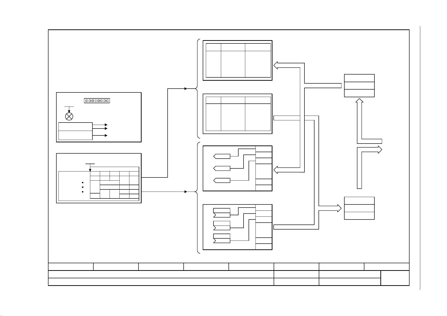
3 Function diagrams
3.5 PROFIdrive communication (PROFIBUS/PROFINET)
SINAMICS G120C
340 List Manual (LH13), 04/2014, A5E33840768B AA
Fig. 3-15 2401 – Overview
- 2401 -
Function diagram
87654321
fp_2401_97_61.vsd
PROFIdrive (PROFIBUS/PROFINET)
SINAMICS G120C DP
07.04.2014 V4.7
Overview
Axxxxx
Fxxxxx
rxxxx
LED
[2468]
[2440] ... [2446]
[2450] ... [2456]
PROFIdrive
.........
... ... ...
.........
... ... ...
PZD3
PZD2
PZD1
...
PZD3
PZD1
PZD2
PZD1
PZD8
Monitoring
Diagnostics
[2410] PROFIBUS address, diagnostics
Permanently assigned
telegrams
Signal assignment
Signal x
[2420] Telegrams and process data
Free telegrams
Interconnecting the permanently assigned receive telegrams.
Signal
Signal
Description
Description
Interconnection
Interconnection
Interconnecting the permanently assigned send telegrams
Interconnecting the free receive telegram
Interconnecting the free send telegram
Receive telegram
Send telegram
PB address
1 ... 126
p0918 (126)
PZD telegr_sel
p0922
p0922 = 999
Header
Data
Trailer
Header
Netto data
Trailer
PZD8
PZD7
PZD7
PZD8
...
[2470]
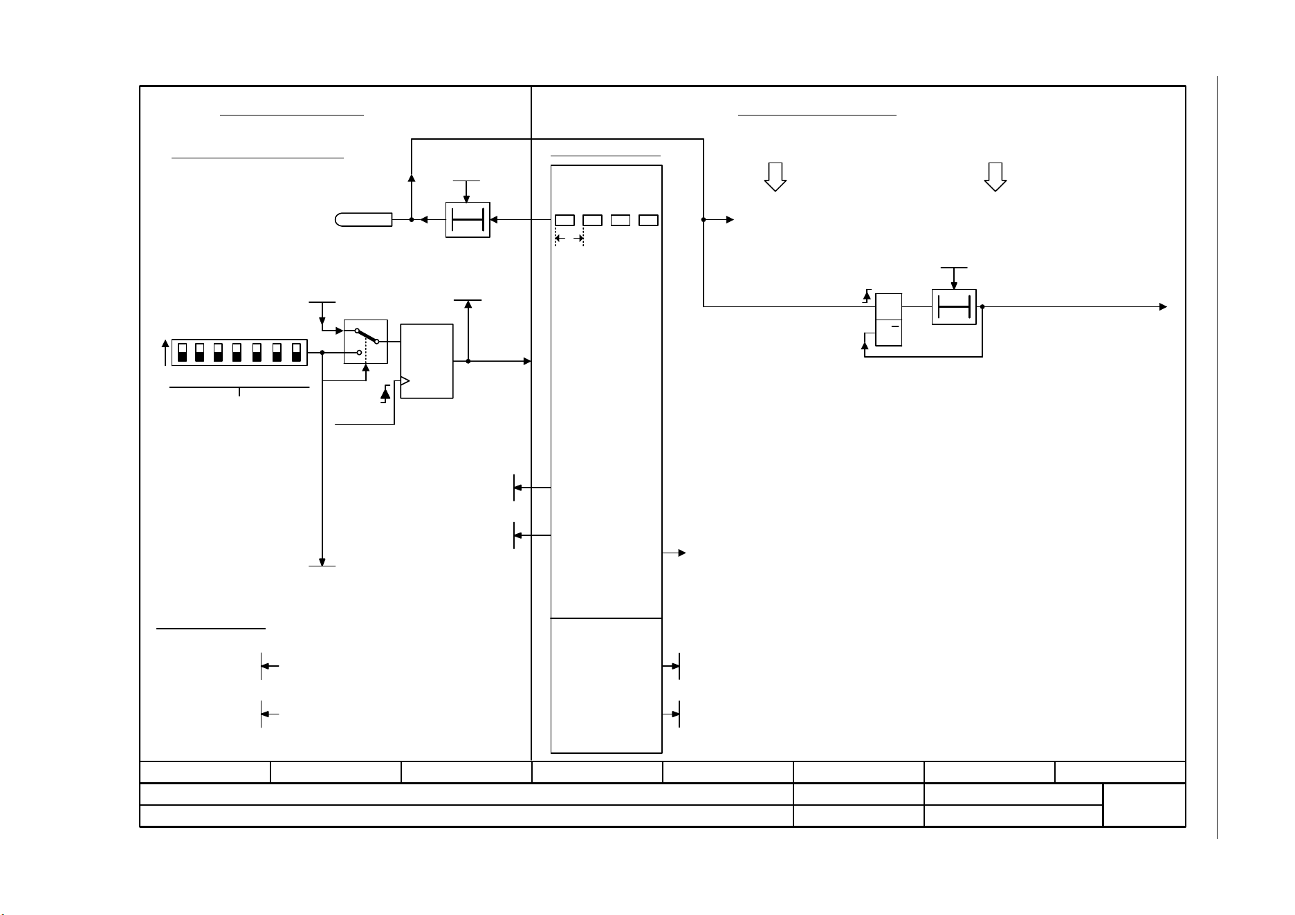
SINAMICS G120C
List Manual (LH13), 04/2014, A5E33840768B AA
341
3 Function diagrams
3.5 PROFIdrive communication (PROFIBUS/PROFINET)
Fig. 3-16 2410 – PROFIBUS (PB) / PROFINET (PN), addresses and diagnostics
- 2410 -
Function diagram
87654321
fp_2410_97_05.vsd
PROFIdrive (PROFIBUS/PROFINET)
G120C DP/PN
07.04.2014 V4.7
PROFIBUS (PB) / PROFINET (PN), addresses and diagnostics
t
S Q
R Q
T0
ON
1 2 4 8 16 32 64
1..126
T0
CU-specific functions
Setting the PROFIBUS address
DIP switch on the control unit
Significance
All DIP switches to ON or OFF
==> set the address using p0918
POWER ON
Actual
PROFIBUS
address
Memory
SET
Drive-specific functions
Monitoring functions
Cyclic telegrams from
the master
Alarms
A01920 "PROFIBUS: Cyclic connection interrupted"
t > t_response <1>
No cyclic telegrams from the
master
Faults
F01910 "PROFIBUS setpoint timeout"
No telegrams from the master
A01900 "PROFIBUS: Configuration telegram incorrect"
The response monitoring time t_An is automatically defined by
the configuration tool (e.g. HW Config made by Siemens) within
the framework of PROFIBUS configuration.
Diagnostic parameters
PD PZD state
r2043.0
PB address
1 ... 126
p0918 (126)
PB status
r2054
PD fault delay
0 ... 100 [s]
p2044 (0)
PB suppl t_monit
0 ... 20000 [ms]
p2047 (0)
p0918
BUS ADDRESS
PB diag standard
r2055[0..2]
PN Name of Station
r61000
PN IP of Station
r61001
PROFINET address
Diag offs recv
r2075
Diag offs send
r2076
PB addr_sw diag
r2057
<1>
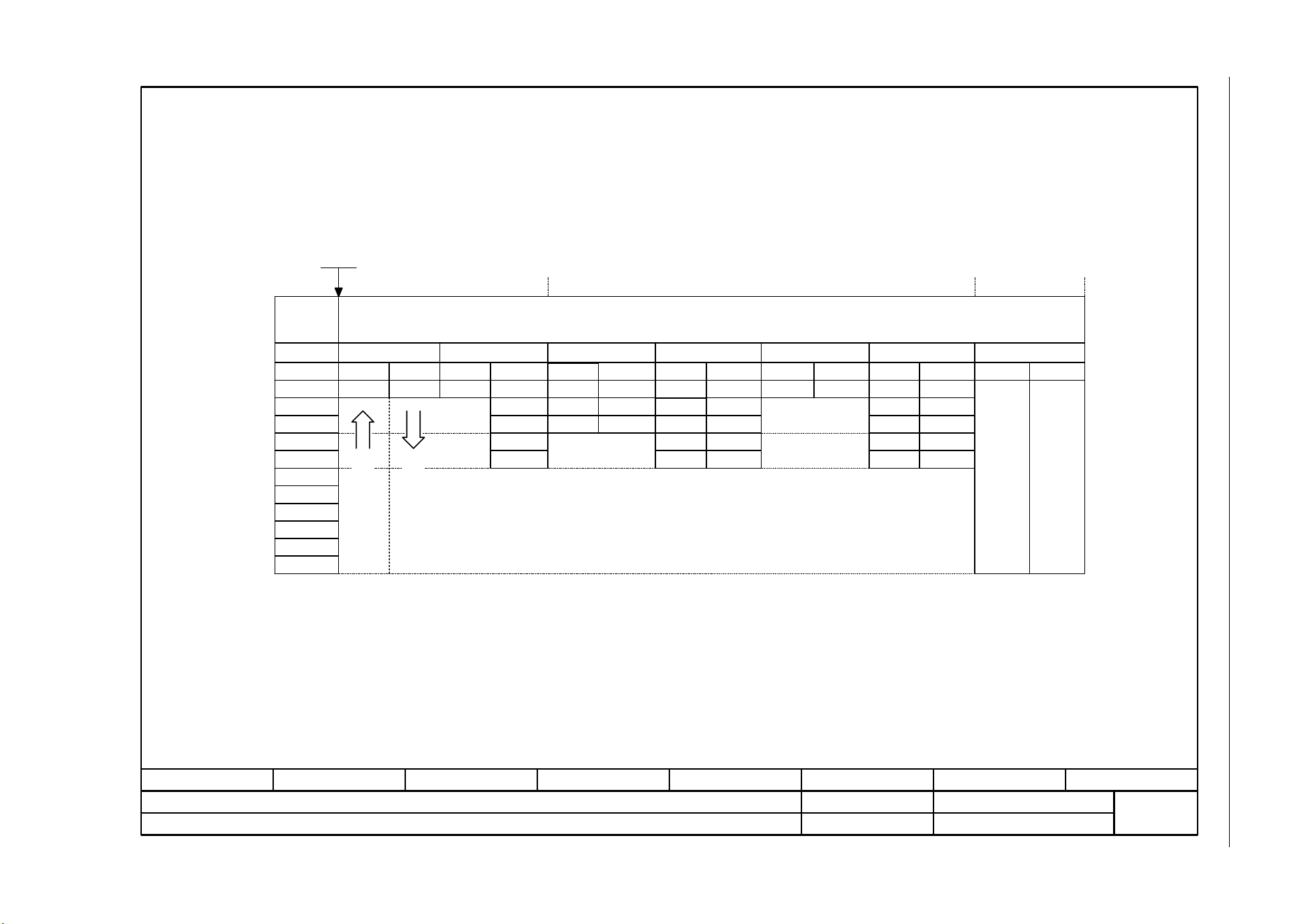
3 Function diagrams
3.5 PROFIdrive communication (PROFIBUS/PROFINET)
SINAMICS G120C
342 List Manual (LH13), 04/2014, A5E33840768B AA
Fig. 3-17 2420 – Telegrams and process data (PZD)
- 2420 -
Function diagram
87654321
fp_2420_97_67.vsd
PROFIdrive (PROFIBUS/PROFINET)
G120C DP/PN
07.04.2014 V4.7
Telegrams and Process Data (PZD)
<2>
If p0922 = 999 is changed to another value, the telegram is automatically assigned.
If p0922 unequal 999 is changed to p0922 = 999, the "old" telegram assignment is maintained!
Freely interconnectable (pre-setting: MELD_NAMUR).
<1>
1
20
PZD6
PZD5
PZD4
PZD1
PZD2
PZD3
STW1 ZSW1
NSOLL_A NIST_A
STW1 ZSW1
MIST_GL
PIST_GL
<2>
NIST_A_GL
IAIST_GL
NSOLL_A
PZD telegr_sel
1 ... 999 [V]
p0922 (1)
Interconnec-
tion is made
according to
Telegram
[2440] [2450] automatically
PZD8
PZD7
350
STW1
ZSW1
ZSW3
NIST_A_GL
IAIST_GL
NSOLL_A
STW3
M_LIM
<3>
Can be freely connected.
999
STW1 <4> ZSW1 <4>
<4> In order to comply with the PROFIdrive profile, PZD1 must be used as control word 1 (STW1) or status word 1 (ZSW1).
p2037 = 2 should be set if STW1 is not transferred with PZD1 as specified in the PROFIdrive profile.
352
STW1 ZSW1
MIST_GL
WARN_CODE
FAULT_CODE
NIST_A_GL
IAIST_GL
NSOLL_A
<3>
<3>
<3>
<3>
353
STW1 ZSW1
NIST_A_GLNSOLL_A
354
STW1 ZSW1
MIST_GL
WARN_CODE
FAULT_CODE
NIST_A_GL
IAIST_GL
NSOLL_A
<3>
<3>
<3>
<3>
Standard telegrams Manufacturer-specific telegrams Free telegram
PZD10
PZD9
PZD12
PZD11
Receive telegram from
PROFIBUS/PROFINET
Send telegram to
PROFIBUS/PROFINET
Receive telegram length freely
selectable via central PROFIdrive
configuration in the master
Transmit telegram length freely
selectable via central PROFIdrive
configuration in the master
<1>
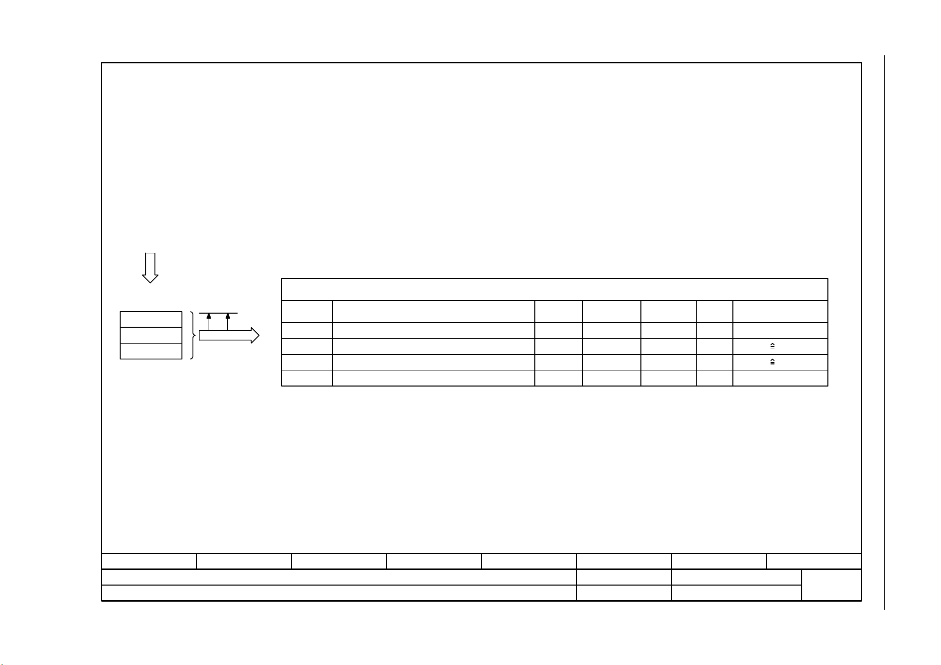
SINAMICS G120C
List Manual (LH13), 04/2014, A5E33840768B AA
343
3 Function diagrams
3.5 PROFIdrive communication (PROFIBUS/PROFINET)
Fig. 3-18 2440 – PZD receive signals interconnection
- 2440 -
Function diagram
87654321
fp_2440_97_64.vsd
PROFIdrive (PROFIBUS/PROFINET)
G120C DP/PN
07.04.2014 V4.7
PZD receive signals interconnection
r2090...r2095 Bit
r2050[0...7] WORD
...
PROFIBUS
PROFINET
STW1
NSOLL_A
<2>
<3>
1
5 p1070
<1>
[2442]
[3030.2]
U16
I16
-
4000 hex p2000
PROFIdrive
receive telegram
Header
Netto data
Trailer
Telegram
assignment
according to p0922
[2420]
Signal receivers for PZD receive signals
Signal Meaning
PROFIdrive
Signal No.
Interconnection
parameter
Function
diagram
Data type Scaling
Control word 1
Speed setpoint A (16-bit)
(bit serial)
When selecting a standard telegram or a manufacturer-specific telegram via p0922, these interconnection parameters
of the command data set CDS are automatically set to 0.
Data type according to to the PROFIdrive profile: I16 = Integer16, U16 = Unsigned16.
Display parameters for receive data according to [2468].
M_LIM
STW3
310
304
p1552, p1554
[6060.1]
[2446]
U16
U16
4000 hex 100 %
Torque limit
Control word 3 (bit serial)
-
Only SIEMENS telegram 350
<4>
<4>
<1>
<2>
<4>
<3>

3 Function diagrams
3.5 PROFIdrive communication (PROFIBUS/PROFINET)
SINAMICS G120C
344 List Manual (LH13), 04/2014, A5E33840768B AA
Fig. 3-19 2441 – STW1 control word interconnection (p2038 = 2)
- 2441 -
Function diagram
87654321
fp_2441_97_61.vsd
PROFIdrive (PROFIBUS/PROFINET)
G120C DP/PN
07.04.2014 V4.7
STW1 control word interconnection (p2038 = 2)
STW1.0
STW1.1
STW1.2
STW1.3
STW1.4
STW1.5
STW1.6
STW1.8
STW1.9
STW1.11
STW1.12
STW1.13
STW1.14
STW1.15
STW1.7
STW1.10
p0848[0] = r2090.2
p0852[0] = r2090.3
p2103[0] = r2090.7
-
-
p0854[0] = r2090.10
p1113[0] = r2090.11
-
-
-
p0810[0] = 2090.15
<3>
p0840[0] = r2090.0
p0844[0] = r2090.1
[2501.3]
[2501.3]
[2501.3]
[2501.3]
[2501.3]
[2546.1]
-
-
[2501.3]
[2505.3]
-
-
-
-
[2501.3]
[2501.3]
[8060]
-
-
[2501]
[3040]
-
-
-
-
-
-
-
-
-
-
-
-
-
-
-
<2>
Signal targets for STW1 in Interface Mode VIK-NAMUR (p2038 = 2)
Signal Meaning
Interconnection
parameters
[Function diagram]
internal control word
[Function diagram]
signal target
Inverted
= ON (pulses can be enabled)
0 = OFF1 (braking with ramp-function generator, then pulse suppression & ready for switching on)
1 = No OFF2 (enable is possible)
0 = OFF2 (immediate pulse suppression and switching on inhibited)
1 = No OFF3 (enable is possible)
0 = OFF3 (braking with the OFF3 ramp p1135, then pulse suppression and switching on inhibited)
1 = Enable operation (pulses can be enabled)
0 = Inhibit operation (suppress pulses)
1 = Ramp-function generator enable
0 = Inhibit ramp-function generator (set the ramp-function generator output to zero)
1 = Continue ramp-function generator
0 = Freezes the ramp-function generator
1 = Setpoint enable
0 = Inhibits the setpoint (the ramp-function generator input is set to zero)
= Acknowledge faults
Reserved
Reserved
Reserved
Reserved
Reserved
1 = Control via PLC
1 = Dir of rot reversal
1 = CDS selection
Used in telegram 20.
Bit 10 in STW1 must be set to ensure that the drive accepts the process data.
Sequence control
Sequence control
Sequence control
Sequence control
Interconnection is not inhibited.
[3070]
[3070]
[3070]
[8565]
p1140[0] = r2090.4
p1141[0] = r2090.5
p1142[0] = r2090.6
<4>
The direction reversal can be locked. See p1110 and p1111.
-
-
-
-
<1>
<1>
<2>
<3>
<4>
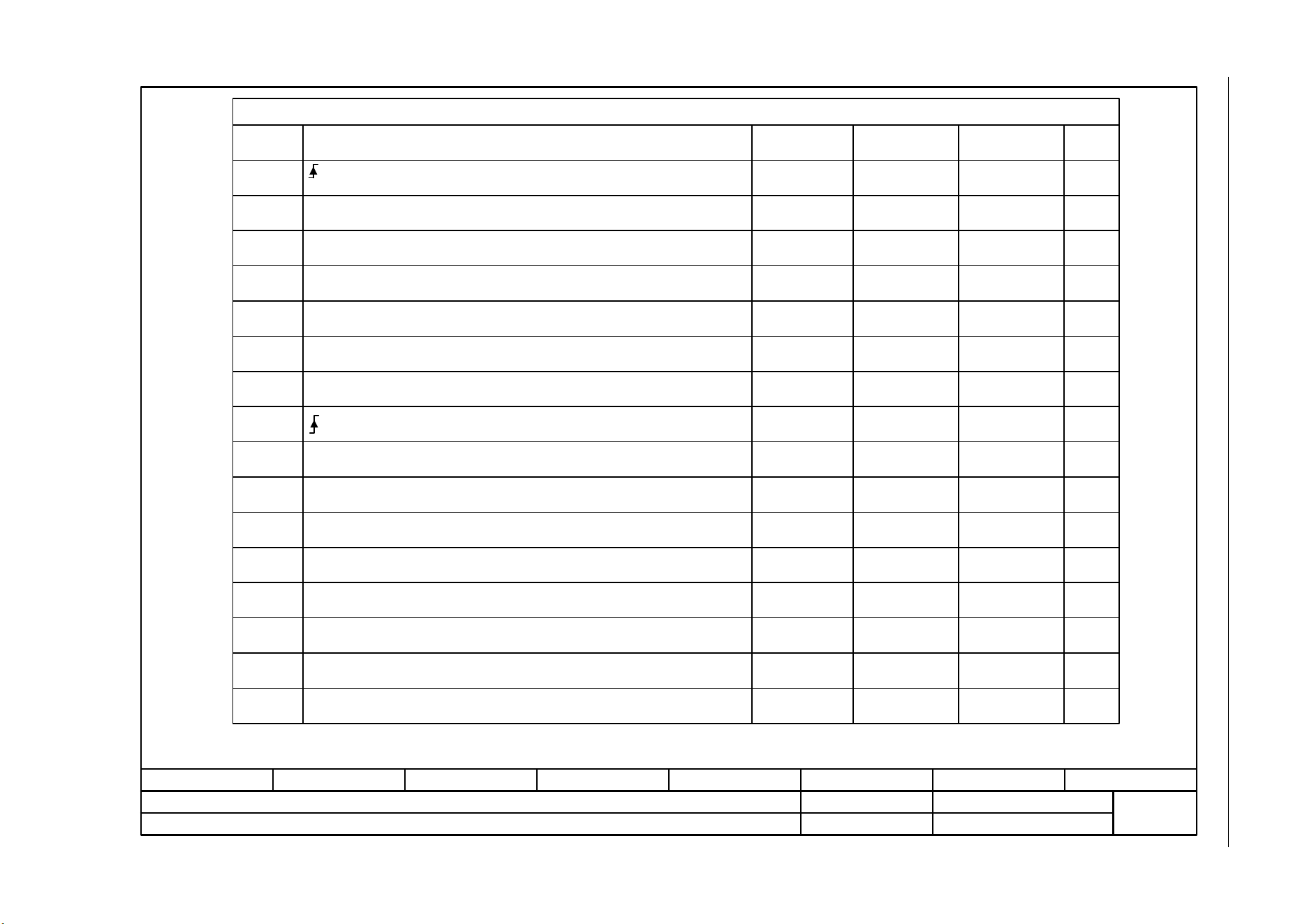
SINAMICS G120C
List Manual (LH13), 04/2014, A5E33840768B AA
345
3 Function diagrams
3.5 PROFIdrive communication (PROFIBUS/PROFINET)
Fig. 3-20 2442 – STW1 control word interconnection (p2038 = 0)
- 2442 -
Function diagram
87654321
fp_2442_97_61.vsd
PROFIdrive (PROFIBUS/PROFINET)
G120C DP/PN
07.04.2014 V4.7
STW1 control word interconnection (p2038 = 0)
STW1.0
STW1.1
STW1.2
STW1.3
STW1.4
STW1.5
STW1.6
STW1.8
STW1.9
STW1.11
STW1.12
STW1.13
STW1.14
STW1.15
STW1.7
STW1.10
p0848[0] = r2090.2
p0852[0] = r2090.3
p2103[0] = r2090.7
-
-
p0854[0] = r2090.10
p1113[0] = r2090.11
-
p1035[0] = r2090.13
p1036[0] = r2090.14
-
p0840[0] = r2090.0
p0844[0] = r2090.1
[2501.3]
[2501.3]
[2501.3]
[2501.3]
[2501.3]
[2546.1]
-
-
[2501.3]
[2505.3]
-
[2505.3]
[2505.3]
-
[2501.3]
[2501.3]
[8060]
-
-
[2501]
[3040]
-
[3020]
[3020]
-
-
-
-
-
-
-
-
-
-
-
-
-
<1>
<1>
Signal targets for STW1 in Interface Mode SINAMICS (p2038 = 0)
Signal Meaning
Interconnection
parameters
[Function diagram]
internal control word
[Function diagram]
signal target
Inverted
0 = OFF1 (braking with ramp-function generator, then pulse suppression & ready for switching on)
= ON (pulses can be enabled)
1 = No OFF2 (enable is possible)
0 = OFF2 (immediate pulse suppression and switching on inhibited)
1 = No OFF3 (enable is possible)
0 = OFF3 (braking with the OFF3 ramp p1135, then pulse suppression and switching on inhibited)
1 = Enable operation (pulses can be enabled)
0 = Inhibit operation (suppress pulses)
1 = Ramp-function generator enable
0 = Inhibit ramp-function generator (set the ramp-function generator output to zero)
1 = Continue ramp-function generator
0 = Freezes the ramp-function generator
1 = Setpoint enable
0 = Inhibits the setpoint (the ramp-function generator input is set to zero)
= Acknowledge faults
Reserved
Reserved
1 = Control via PLC
1 = Dir of rot reversal
Reserved
1 = Motorized potentiometer, setpoint, raise
1 = Motorized potentiometer, setpoint, lower
Reserved
Bit 10 in STW1 must be set to ensure that the drive accepts the process data.
Sequence control
Sequence control
Sequence control
Sequence control
[3070]
[3070]
[3070]
p1140[0] = r2090.4
p1141[0] = r2090.5
p1142[0] = r2090.6
-
-
-
-
<2>
<2> The direction reversal can be locked. See p1110 and p1111.

3 Function diagrams
3.5 PROFIdrive communication (PROFIBUS/PROFINET)
SINAMICS G120C
346 List Manual (LH13), 04/2014, A5E33840768B AA
Fig. 3-21 2446 – STW3 control word interconnection
- 2446 -
Function diagram
87654321
fp_2446_97_05.vsd
PROFIdrive (PROFIBUS/PROFINET)
G120C DP/PN
07.04.2014 V4.7
STW3 control word interconnection
<1>
STW3.0
STW3.1
STW3.2
STW3.3
STW3.4
STW3.5
STW3.6
STW3.8
STW3.9
STW3.11
STW3.12
STW3.13
STW3.14
STW3.15
STW3.7
STW3.10
p1022[0] = r2093.2
p1023[0] = r2093.3
-
-
-
-
p2200[0] = r2093.8
p1230[0] = r2093.9
-
-
-
p2106[0] = r2093.13
-
-
p1020[0] = r2093.0
p1021[0] = r2093.1
[2513.2]
[2513.2]
-
-
-
-
[2513.2]
[2513.2]
-
-
-
[2513.2]
-
-
[3010.2]
[2513.2]
[3010.2]
[3010.2]
-
-
-
-
[7958.4]
[7017.1]
-
-
-
[8060.1]
-
-
[3010.2]
[3010.2]
-
-
-
-
-
-
-
-
-
-
-
-
-
-
-
-
<1>
Signal targets for STW3 in Interface Mode SINAMICS
Signal
Meaning
Interconnection
parameters
[Function diagram]
internal control word
[Function diagram]
signal target
Inverted
Used in telegram 350.
1 = Fixed setp bit 0
1 = Fixed setp bit 1
1 = Fixed setp bit 2
1 = Fixed setp bit 3
Reserved
Reserved
1 = Technology controller enable
1 = DC brake enable
Reserved
0 = External fault 1 (F07860)
Reserved
Reserved
Reserved
Reserved
Reserved
Reserved
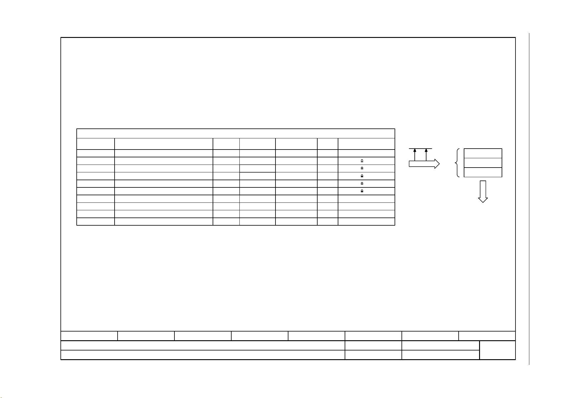
SINAMICS G120C
List Manual (LH13), 04/2014, A5E33840768B AA
347
3 Function diagrams
3.5 PROFIdrive communication (PROFIBUS/PROFINET)
Fig. 3-22 2450 – PZD send signals interconnection
- 2450 -
Function diagram
87654321
fp_2450_97_64.vsd
PROFIdrive (PROFIBUS/PROFINET)
G120C DP/PN
07.04.2014 V4.7
PZD send signals interconnection
PZD send word 1...8
p2051[0...7] WORD
r2053[0...7] WORD
...
U16 -r2089[0]2 [2452]ZSW1
I16 4000 hex p2000r0063[0]6 -NIST_A
FAULT_CODE
U16
r2131301 [8060] U16
r2132303 [8065]WARN_CODE
U16r311358MELD_NAMUR -
4000 hex p2004I16r0082[1]54 [6799]PIST_GLATT
4000 hex p2003I16r0080[1]53 [6799]MIST_GLATT
4000 hex p2002I16r0068[1]51 [6799]IAIST_GLATT
4000 hex p2000I16r0063[1]57 -NIST_A_GLATT
PROFIBUS
PROFINET
Signal sources for PZD send signals
Signal
PROFIdrive
Signal No.
Interconnection
parameter
Function diagram Data type Scaling
Status word 1
Actual speed A (16 bit)
Absolute actual current, smoothed
Actual torque smoothed
Power factor, smoothed
Actual speed, smoothed
VIK-NAMUR message bit bar
Fault code
Alarm code
PROFIdrive send
telegram
Header
Data
Telegram
assignment
according to p0922
[2420]
Trailer
Data type according to the PROFIdrive profile: I16 = Integer16, U16 = Unsigned16.
Description
U16r0053305 [2456]ZSW3
Status word 3
<1>
<1>
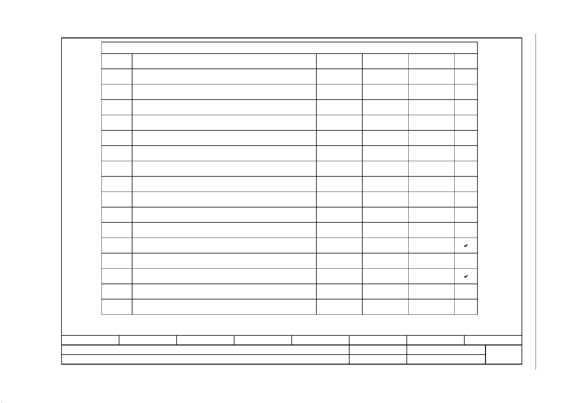
3 Function diagrams
3.5 PROFIdrive communication (PROFIBUS/PROFINET)
SINAMICS G120C
348 List Manual (LH13), 04/2014, A5E33840768B AA
Fig. 3-23 2451 – ZSW1 status word interconnection (p2038 = 2)
- 2451 -
Function diagram
87654321
fp_2451_97_61.vsd
PROFIdrive (PROFIBUS/PROFINET)
G120C DP/PN
07.04.2014 V4.7
ZSW1 status word interconnection (p2038 = 2)
ZSW1.0
ZSW1.1
ZSW1.2
ZSW1.3
ZSW1.4
ZSW1.5
ZSW1.6
ZSW1.8
ZSW1.9
ZSW1.11
ZSW1.12
ZSW1.13
ZSW1.14
ZSW1.15
ZSW1.7
ZSW1.10
p2080[2] = r0899.2
p2080[3] = r2139.3
p2080[4] = r0899.4
p2080[5] = r0899.5
p2080[6] = r0899.6
p2080[7] = r2139.7
p2080[8] = r2197.7
p2080[9] = r0899.9
p2080[10] = r2199.1
p2080[11] = r0056.13
-
p2080[13] = r2135.14
p2080[0] = r0899.0
p2080[1] = r0899.1
p2080[14] = r2197.3
[2503.7]
[2548.7]
[2503.7]
[2503.7]
[2503.7]
[2548.7]
[2534.7]
[2503.7]
[2537.7]
[2522.7]
-
[2548.7]
-
[2503.7]
[2503.7]
[2534.7]
[8060]
[8065]
[8011]
[2503]
[8010]
[6060]
-
[8016]
-
[8011]
-
-
-
-
-
-
-
-
-
-
-
-
-
-
p2080[15] = r0836.0
<2>
Signal sources for ZSW1 in Interface Mode VIK-NAMUR (p2038 = 2)
Signal Meaning
Interconnection
parameters
[Function diagram]
internal control word
[Function diagram]
signal target
Inverted
1 = Ready for switching on
1 = Ready for operation (DC link loaded, pulses inhibited)
1 = Operation enabled (drive follows n_set)
1 = Fault present
1 = No coast down active (OFF2 inactive)
1 = No quick stop active (OFF3 inactive)
1 = Switching on inhibited active
1 = Alarm present
1 = Speed setpoint - actual value deviation within tolerance t_off
1 = Control requested
1 = f or n comparison value reached/exceeded
1 = I, M, or P limit not reached
1 = No motor overtemperature alarm
1 = Motor rotates forwards (n_act 0)
1 = Display CDS
Reserved
The ZSW1 is generated using the binector-connector converter (BI: p2080[0...15], inversion: p2088[0].0...p2088[0].15).
Sequence control
Sequence control
Sequence control
Sequence control
Sequence control
Sequence control
Interconnection is not inhibited.
<1>
<1>
<2>
SINAMICS G120C
List Manual (LH13), 04/2014, A5E33840768B AA
349
3 Function diagrams
3.5 PROFIdrive communication (PROFIBUS/PROFINET)
Fig. 3-24 2452 – ZSW1 status word interconnection (p2038 = 0)
- 2452 -
Function diagram
87654321
fp_2452_97_61.vsd
PROFIdrive (PROFIBUS/PROFINET)
G120C DP/PN
07.04.2014 V4.7
ZSW1 status word interconnection (p2038 = 0)
ZSW1.0
ZSW1.1
ZSW1.2
ZSW1.3
ZSW1.4
ZSW1.5
ZSW1.6
ZSW1.8
ZSW1.9
ZSW1.11
ZSW1.12
ZSW1.13
ZSW1.14
ZSW1.15
ZSW1.7
ZSW1.10
p2080[2] = r0899.2
p2080[3] = r2139.3
p2080[4] = r0899.4
p2080[5] = r0899.5
p2080[6] = r0899.6
p2080[7] = r2139.7
p2080[8] = r2197.7
p2080[9] = r0899.9
p2080[10] = r2199.1
p2080[11] = r1407.7
p2080[13] = r2135.14
p2080[15] = r2135.15
p2080[0] = r0899.0
p2080[1] = r0899.1
p2080[14] = r2197.3
[2503.7]
[2548.7]
[2503.7]
[2503.7]
[2503.7]
[2548.7]
[2534.7]
[2503.7]
[2536.7]
[2522.7]
[2548.7]
[2548.7]
[2503.7]
[2503.7]
[2534.7]
[8060]
[8065]
[8011]
[2503]
[8010]
[6060]
[8016]
[8014]
[8011]
-
-
-
-
-
-
-
-
-
-
-
-
-
Signal sources for ZSW1 im Interface Mode SINAMICS (p2038 = 0)
Signal Meaning
Interconnection
parameters
[Function diagram]
internal control word
[Function diagram]
signal target
Inverted
1 = Ready for switching on
1 = Ready for operation (DC link loaded, pulses inhibited)
1 = Operation enabled (drive follows n_set)
1 = Fault present
1 = No coast down active (OFF2 inactive)
1 = No quick stop active (OFF3 inactive)
1 = Switching on inhibited active
1 = Alarm present
1 = Speed setpoint - actual value deviation within tolerance t_off
1 = Control requested
1 = f or n comparison value reached/exceeded
1 = I, M, or P limit not reached
1 = Open holding brake
1 = No motor overtemperature alarm
1 = Motor rotates forwards (n_act 0)
1 = No alarm, thermal overload, power unit
The ZSW1 is generated using the binector-connector converter (BI: p2080[0...15], inversion: p2088[0].0...p2088[0].15).
The drive is ready to accept data.
Sequence control
Sequence control
Sequence control
[2701][2503.7]p2080[12] = r0899.12
Sequence control
Sequence control
Sequence control
<1>
<2>
<1>
<2>
3 Function diagrams
3.5 PROFIdrive communication (PROFIBUS/PROFINET)
SINAMICS G120C
350 List Manual (LH13), 04/2014, A5E33840768B AA
Fig. 3-25 2456 – ZSW3 status word interconnection
- 2456 -
Function diagram
87654321
fp_2456_97_61.vsd
PROFIdrive (PROFIBUS/PROFINET)
G120C DP/PN
07.04.2014 V4.7
ZSW3 status word interconnection
ZSW3.0
ZSW3.1
ZSW3.2
ZSW3.3
ZSW3.4
ZSW3.5
ZSW3.6
ZSW3.8
ZSW3.9
ZSW3.11
ZSW3.12
ZSW3.13
ZSW3.14
ZSW3.15
ZSW3.7
ZSW3.10
p2051[3] = r0053
[2511.7]
[2511.7]
[2511.7]
[2511.7]
[2511.7]
[2511.7]
[2511.7]
[2511.7]
[2511.7]
[2511.7]
-
-
-
[2511.7]
[2511.7]
-
-
-
-
-
<1>
-
-
-
-
-
-
-
-
-
-
-
-
-
-
-
-
Signal sources for ZSW3 im Interface Mode SINAMICS
Signal Meaning
Interconnection
parameters
[Function diagram]
internal status word
[Function diagram]
signal source
Inverted
Used in telegrams 350.
1 = DC braking active
1 = |n_act| > p1226 (n_standstill)
1 = |n_act| > p1080 (n_min)
1 = I_act >= p2170
1 = |n_act| > p2155
1 = |n_act| <= p2155
1 = |n_act| >= r1119 (n_set)
1 = Vdc <= p2172
1 = Vdc > p2172
1 = Ramping finished
1 = Technology controller output at the lower limit
1 = Technology controller output at the upper limit
Reserved
Reserved
Reserved
Reserved
[7017.5]
[2534.7]
[2534.7]
[2534.7]
[2534.7]
[2534.7]
[2534.7]
[2534.7]
[2534.7]
[3080.7]
[7958.7]
[7958.7]
<1>
SINAMICS G120C
List Manual (LH13), 04/2014, A5E33840768B AA
351
3 Function diagrams
3.5 PROFIdrive communication (PROFIBUS/PROFINET)
Fig. 3-26 2468 – Receive telegram, free interconnection via BICO (p0922 = 999)
- 2468 -
Function diagram
87654321
fp_2468_97_61.vsd
PROFIdrive (PROFIBUS/PROFINET)
G120C DP/PN
07.04.2014 V4.7
Receive telegram, free interconnection via BICO (p0922 = 999)
...
...
1
0
1
1
0
1
1
0
1
1
0
1
PROFINET
PROFIBUS
PROFIdrive
receive telegram
Header
Data
Trailer
PZD receive word 1
PZD receive word 2
PZD receive word 3
PZD receive word 4
PZD receive word 5
PZD receive word 6
In order to maintain the PROFIdrive profile, receive word 1 must be used as control word (STW1)
(due to bit 10 "control requested").
Using the connector-binector converters, the bits can be extracted from two of the PZD receive words 3 to 8 and used as binectors.
The following representation applies for words: 4000 hex = 100 %.
The reference variables p200x apply for the ongoing interconnection (100 % -> p200x).
The following applies for temperature values: 100 °C -> 100 % = 4000 hex, 0 °C -> 0 %.
Reference quantities for further
interconnection
p200x
2 connector-binector converter
Con/bin outp
r2094
Con/bin outp inv
p2098 [0].0
Con/bin outp inv
p2098 [0].15
Con/bin outp inv
p2098 [1].0
Con/bin outp inv
p2098 [1].15
Con/bin S_src
(0)
p2099[1]
Con/bin S_src
(0)
p2099[0]
r2050
PZD recv word
[0]
r2050
PZD recv word
[1]
r2050
PZD recv word
[2]
r2050
PZD recv word
[3]
r2050
PZD recv word
[4]
r2050
PZD recv word
[5]
Con/bin outp
r2094.15
Con/bin outp
r2095.0
Con/bin outp
r2095.15
.0
PZD1 recv bitw
r2090.0
PZD1 recv bitw
r2090.15
PZD2 recv bitw
r2091.0
PZD2 recv bitw
r2091.15
PZD receive word 7
PZD receive word 8
r2050
PZD recv word
[6]
r2050
PZD recv word
[7]
...
PZD3 recv bitw
r2092.0
PZD3 recv bitw
r2092.15
...
PZD4 recv bitw
r2093.0
PZD4 recv bitw
r2093.15
PZD receive word 9
PZD receive word 10
PZD receive word 11
PZD receive word 12
r2050
PZD recv word
[8]
r2050
PZD recv word
[9]
r2050
PZD recv word
[10]
r2050
PZD recv word
[11]
r2060
PZD recv DW
[2]
r2060
PZD recv DW
[3]
r2060
PZD recv DW
r2060
PZD recv DW
[5]
r2060
PZD recv DW
[6]
r2060
PZD recv DW
[4]
[7]
r2060
PZD recv DW
[8]
r2060
PZD recv DW
[9]
r2060
PZD recv DW
[10]
r2060
PZD recv DW
[0]
r2060
PZD recv DW
[1]
Every PZD word can be assigned a word or a double word. Only one of the 2 interconnection parameters r2050 or r2060 can have a value <> 0 for a PZD word.
When interconnecting a connector output multiple times all the connector inputs must have either Integer or FloatingPoint data type.
<1>
<5> <6>
<5> <6>
<3>
<2>
<2>
<2>
<3>
<4>
<1>
<5>
<6>
3 Function diagrams
3.5 PROFIdrive communication (PROFIBUS/PROFINET)
SINAMICS G120C
352 List Manual (LH13), 04/2014, A5E33840768B AA
Fig. 3-27 2470 – Send telegram, free interconnection via BICO (p0922 = 999)
- 2470 -
Function diagram
87654321
fp_2470_97_61.vsd
PROFIdrive (PROFIBUS/PROFINET)
G120C DP/PN
07.04.2014 V4.7
Send telegram, free interconnection via BICO (p0922 = 999)
<1>
<2>
...
<2>
<1>
PROFIBUS
PROFINET
<1>
Reference quantities for
further interconnection
p200x
To comply with the PROFIdrive profile, send word 1 must be used as status word 1 (ZSW1).
Physical word values are inserted in the telegram as referenced variables. p200x apply as reference variables (telegram contents = 4000 hex, if the input variable has the value p200x).
The following applies for temperature values: 100 °C -> 100 % = 4000
PZD send word 1
PZD send word 2
PZD send word 3
PZD send word 4
PZD send word 5
PZD send word 6
PZD send word 7
PZD send word 8
PROFIdrive send
telegram
Header
Data
Trailer
Diag send word
r2053
[0…13]
PZD send word
(0)
p2051[0]
PZD send word
(0)
p2051[1]
PZD send word
(0)
p2051[2]
PZD send word
(0)
p2051[3]
PZD send word
(0)
p2051[4]
PZD send word
(0)
p2051[5]
PZD send word
(0)
p2051[6]
PZD send word
(0)
p2051[7]
Diag send DW
r2063
PZD send DW
(0)
p2061[0]
PZD send DW
(0)
p2061[1]
PZD send DW
(0)
p2061[2]
PZD send DW
(0)
p2061[3]
PZD send DW
(0)
p2061[4]
PZD send DW
(0)
p2061[5]
PZD send DW
(0)
p2061[6]
PZD send word 9
PZD send word 10
PZD send word 11
PZD send word 12
PZD send word
(0)
p2051[8]
PZD send word
(0)
p2051[9]
PZD send word
(0)
p2051[10]
PZD send word
(0)
p2051[11]
PZD send DW
(0)
p2061[7]
PZD send DW
(0)
p2061[8]
PZD send DW
(0)
p2061[9]
PZD send DW
(0)
p2061[10]
<3>
<3>
A PZD send word can either be supplied via connector input p2051[x] (WORD) or via p2061[x] (DWORD).
The two corresponding connector inputs cannot be interconnected.
<3>
[0…12]
PZD 1+2
PZD 2+3
PZD 3+4
PZD 4+5
PZD 5+6
PZD 6+7
PZD 7+8
PZD 8+9
PZD 9+10
PZD 10+11
PZD 11+12
PZD send word 13
PZD send word 14
PZD send word
(0)
p2051[13]
PZD send DW
(0)
p2061[12]
PZD 13+14
PZD send word
(0)
p2051[12]
PZD send DW
(0)
p2061
[11]
PZD 12+13

SINAMICS G120C
List Manual (LH13), 04/2014, A5E33840768B AA
353
3 Function diagrams
3.6 CANopen communication
3.6 CANopen communication
Function diagrams
9204 – Receive telegram, free PDO mapping (p8744 = 2) 354
9206 – Receive telegram, Predefined Connection Set (p8744 = 1) 355
9208 – Send telegram, free PDO mapping (p8744 = 2) 356
9210 – Send telegram, Predefined Connection Set (p8744 = 1) 357
9220 – Control word, CANopen 358
9226 – Status word, CANopen 359
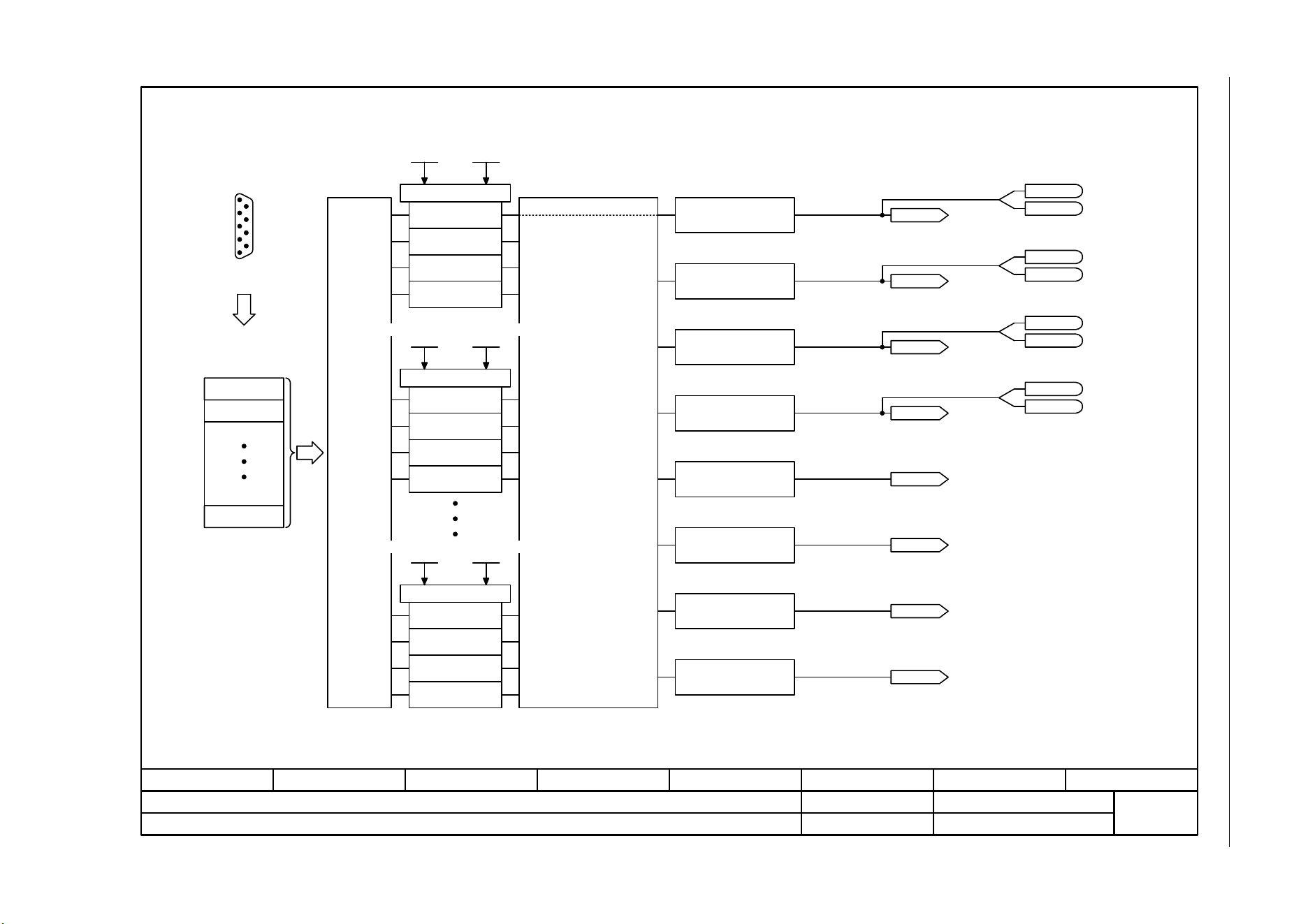
3 Function diagrams
3.6 CANopen communication
SINAMICS G120C
354 List Manual (LH13), 04/2014, A5E33840768B AA
Fig. 3-28 9204 – Receive telegram, free PDO mapping (p8744 = 2)
RPDO 1
- 9204 -
Function diagram
87654321
fp_9204_97_68.vsd
CANopen
SINAMICS G120C CAN
07.04.2014 V4.7
Receive telegram, free PDO mapping (p8744 = 2)
Bit 15r2090.15
Bit 0
...
COB-ID
<1>
<2>
RPDO 2
RPDO 8
Object
Object
Object
Object
Receive PDO 2
p8701
Mapping RPDO 2
p8711
Object
Object
Sub-D socket
CAN bus
CANopen
receive telegram
Automatic assignment of the
RPDOs to the receive buffer.
The assignment is made
from RPDO 1, RPDO 2 ...
RPDO 8 and from receiver
buffer word.
Objects available a multiple
number of times are
marshalled to the same
position in the receive buffer.
Evaluation
of the
COB-ID
Receive PDO 8
p8707
Mapping RPDO 8
p8717
PZD receive word
Receive buffer
PZD receive word
PZD receive word
PZD receive word
PZD receive word
PZD receive word
PZD receive word
PZD receive word
To use automatic BICO interconnection (p8790 = 1), one of the receive words 1 - 4 must be used as control word 1 (STW1).
Telegram: up to 4 words or 64 bits. The sum of the various objects must not exceed 8 words.
RPDO: Receive Process Data Object
COB-ID: CAN object identification
PZD1 recv bitw
r2090
Bit 15
r2091.15
PZD2 recv bitw
r2091
Bit 15
r2092.15
PZD3 recv bitw
r2092
Bit 15
r2093.15
PZD4 recv bitw
r2093
r2050
PZD recv word
r2050
PZD recv word
r2050
PZD recv word
r2050
PZD recv word
r2050
PZD recv word
r2050
PZD recv word
r2050
PZD recv word
r2050
PZD recv word
Receive PDO 1
0000 hex ... 8000 06DF hex
p8700[0..1] (8000 06DF hex)
Mapping RPDO 1
0000 hex ... FFFF FFFF hex
p8710[0..3] (0000 hex)
1
4
<1>
<2>
1
2
3
4
1
2
3
4
5
6
7
8
Object
Object
Object
Object
1
2
3
4
Object
Object
Object
Object
1
2
3
4
.0
[0]
.0
.0
.0
Bit 0
...
Bit 0
...
Bit 0
...
[1]
[2]
[3]
[4]
[5]
[6]
[7]
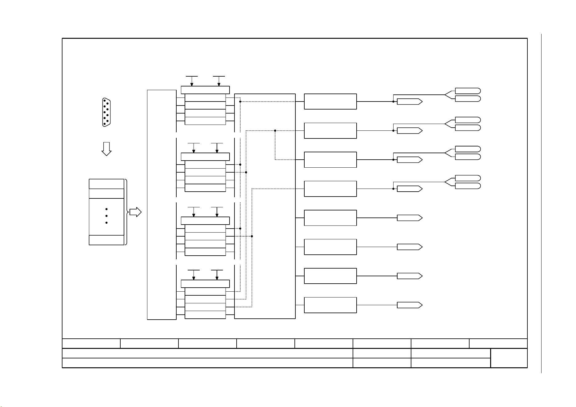
SINAMICS G120C
List Manual (LH13), 04/2014, A5E33840768B AA
355
3 Function diagrams
3.6 CANopen communication
Fig. 3-29 9206 – Receive telegram, Predefined Connection Set (p8744 = 1)
- 9206 -
Function diagram
87654321
fp_9206_97_68.vsd
CANopen
SINAMICS G120C CAN
07.04.2014 V4.7
Receive telegram, Predefined Connection Set (p8744 = 1)
<2>
Automatic assignment of the
RPDOs to the receive buffer.
The assignment is
made from RPDO 1,
RPDO 2 ... RPDO 8
and from receiver
buffer word.
Objects available a
multiple number of
times are
marshalled to the
same position in the
receive buffer.
Evaluation
of the
COB-ID
Telegram: up to 4 words or 64 bits. The sum of the various objects must not exceed 8 words.
RPDO: Receive Process Data Object
COB-ID: CAN object identification
60400010
RPDO 1
Receive PDO 2
p8701
Mapping RPDO 2
p8711
Receive PDO 3
p8702
Mapping RPDO 3
p8712
Receive PDO 4
p8703
Mapping RPDO 4
p8713
To use automatic BICO interconnection (p8790 = 1), one of the receive words 1 - 4 must be used as control word 1 (STW1).
Bit 15r2090.15
PZD1 recv bitw
r2090
Bit 15
r2091.15
PZD2 recv bitw
r2091
Bit 15
r2092.15
PZD3 recv bitw
r2092
Bit 15
r2093.15
PZD4 recv bitw
r2093
r2050
PZD recv word
r2050
PZD recv word
r2050
PZD recv word
r2050
PZD recv word
r2050
PZD recv word
r2050
PZD recv word
r2050
PZD recv word
r2050
PZD recv word
<1>
Receive PDO 1
0000 hex ... 8000 06DF hex
p8700[0..1] (8000 06DF hex)
Mapping RPDO 1
0000 hex ... FFFF FFFF hex
p8710[0..3] (0000 hex)
COB-ID
Object
Object
Sub-D socket
CAN bus
CANopen
receive telegram
1
4
RPDO 3
RPDO 4
60400010
RPDO 2
60420010
PZD receive word
Receive buffer
PZD receive word
PZD receive word
PZD receive word
PZD receive word
PZD receive word
PZD receive word
PZD receive word
1
2
3
4
5
6
7
8
.0
.0
.0
.0
[0]
[1]
[2]
[3]
[4]
[5]
[6]
[7]
Bit 0
...
Bit 0
...
Bit 0
...
Bit 0
...
<1>
<2>
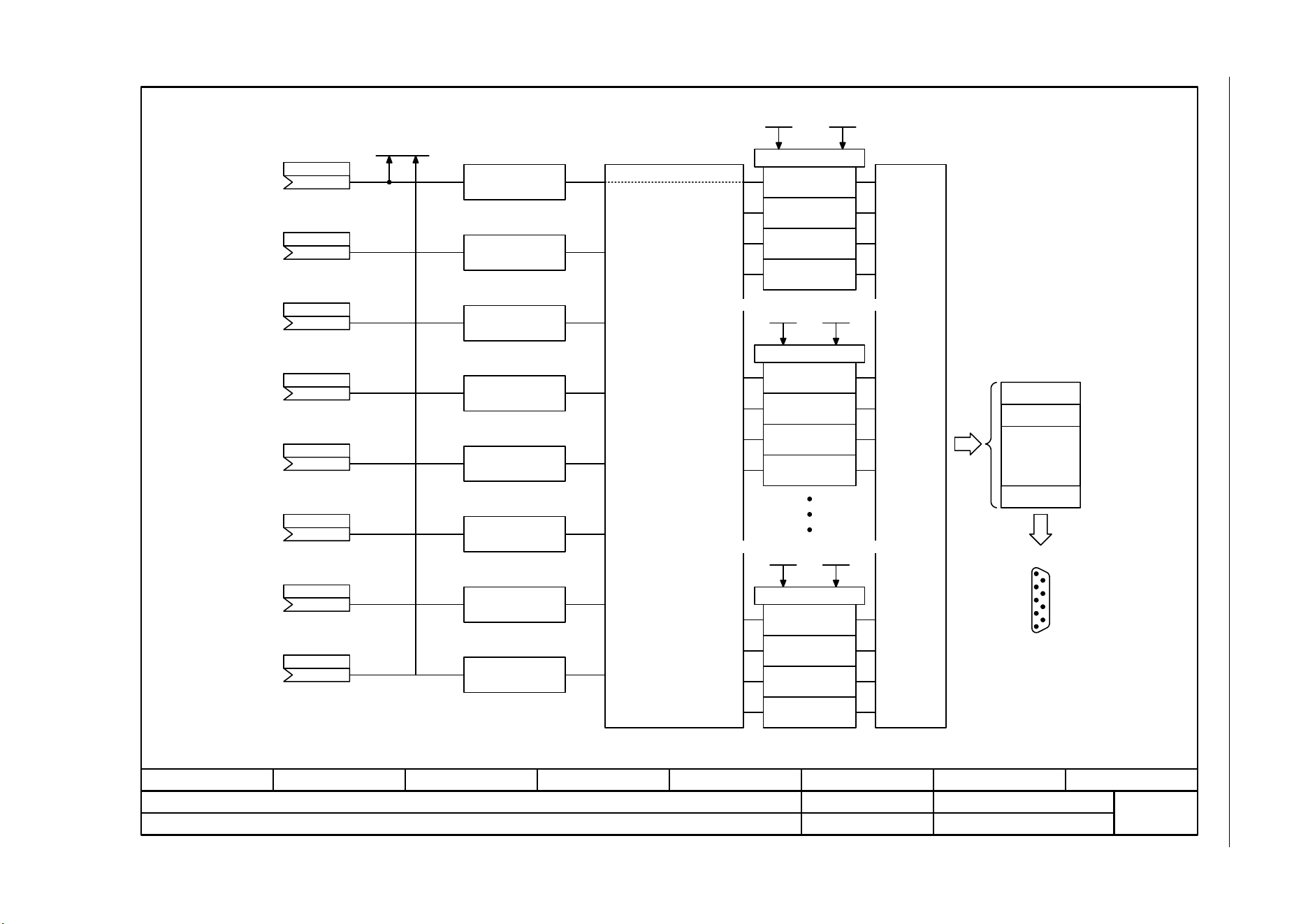
3 Function diagrams
3.6 CANopen communication
SINAMICS G120C
356 List Manual (LH13), 04/2014, A5E33840768B AA
Fig. 3-30 9208 – Send telegram, free PDO mapping (p8744 = 2)
- 9208 -
Function diagram
87654321
fp_9208_97_68.vsd
CANopen
SINAMICS G120C CAN
07.04.2014 V4.7
Send telegram, free PDO mapping (p8744 = 2)
...
.
.
.
COB-ID
<1>
TPDO 1
CANopen send words 1 ... 7
Send buffer
PZD send word
Automatic assignment of the
send buffer to the TPDOs
The assignment is made
from send buffer 1 and from
TPDO 1.
Objects that occur a
multiple number of times
are updated from the same
send buffer.
Object
Object
Object
Object
Transmit PDO 2
p8721
Mapping TPDO 2
p8731
Transmit PDO 8
p8727
Mapping TPDO 8
p8737
Object
Object
Sub-D socket
CAN bus
TPDO: Transmit Process Data Object
COB-ID: CAN object identification
Telegram: up to 4 words or 64 bits. The sum of the various objects must not exceed 8 words.
Evaluation of
the COB-ID
and data
transfer type
CANopen send telegram
PZD send word
(0)
p2051
PZD send word
(0)
p2051
PZD send word
(0)
p2051
PZD send word
(0)
p2051
PZD send word
(0)
p2051
PZD send word
(0)
p2051
PZD send word
(0)
p2051
PZD send word
(0)
p2051
Transmit PDO 1
0000 hex ... C000 06DF hex
p8720[0..4] (C000 06DF hex)
Mapping TPDO 1
0000 hex ... FFFF FFFF hex
p8730[0..3] (0000 hex)
Diag send word
r2053[0..13]
[0]
[1]
[2]
[3]
[4]
[5]
[6]
[7]
1
PZD send word 2
PZD send word 3
PZD send word 4
PZD send word 5
PZD send word 6
PZD send word 7
PZD send word 8
1
2
3
4
TPDO 2
Object
Object
Object
Object
1
2
3
4
TPDO 8
Object
Object
Object
Object
1
2
3
4
1
4
<1>
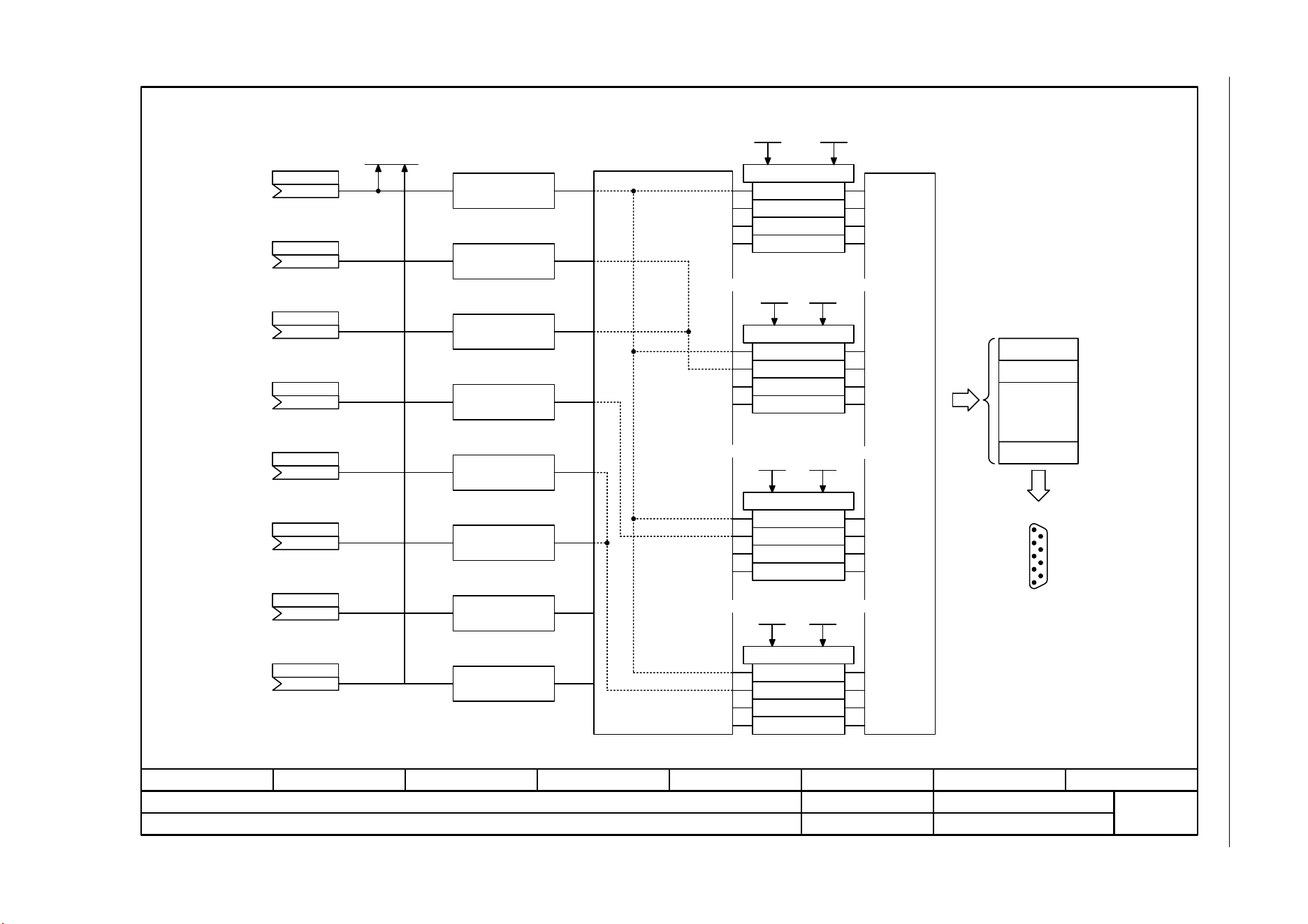
SINAMICS G120C
List Manual (LH13), 04/2014, A5E33840768B AA
357
3 Function diagrams
3.6 CANopen communication
Fig. 3-31 9210 – Send telegram, Predefined Connection Set (p8744 = 1)
- 9210 -
Function diagram
87654321
fp_9210_97_68.vsd
CANopen
SINAMICS G120C CAN
07.04.2014 V4.7
Send telegram, Predefined Connection Set (p8744 = 1)
<1>
60410010
60410010
60440010
TPDO 1
TPDO 2
TPDO 3
TPDO 4
CANopen send words 1 ... 7
Automatic assignment of the
send buffer to the TPDOs
Transmit PDO 2
p8721
Mapping TPDO 2
p8731
Transmit PDO 4
p8723
Mapping TPDO 4
p8733
Mapping TPDO 3
p8732
Transmit PDO 3
p8722
Evaluation of
the COB-ID
and data
transfer type
TPDO: Transmit Process Data Object
COB-ID: CAN object identification
Telegram: up to 4 words or 64 bits. The sum of the various objects must not exceed 8 words.
Objects that
occur a multiple
number of times
are updated from
the same send
buffer.
The assignment is
made from send
buffer 1 and from
TPDO 1.
Transmit PDO 1
0000 hex ... C000 06DF hex
p8720[0..4] (C000 06DF hex)
Mapping TPDO 1
0000 hex ... FFFF FFFF hex
p8730[0..3] (0000 hex)
...
Send buffer
PZD send word
PZD send word
(0)
p2051
PZD send word
(0)
p2051
PZD send word
(0)
p2051
PZD send word
(0)
p2051
PZD send word
(0)
p2051
PZD send word
(0)
p2051
PZD send word
(0)
p2051
PZD send word
(0)
p2051
Diag send word
r2053[0..13]
[0]
[1]
[2]
[3]
[4]
[5]
[6]
[7]
1
PZD send word 2
PZD send word 3
PZD send word 4
PZD send word 5
PZD send word 6
PZD send word 7
PZD send word 8
.
.
.
COB-ID
Object
Object
Sub-D socket
CAN bus
CANopen send telegram
1
4
<1>
3 Function diagrams
3.6 CANopen communication
SINAMICS G120C
358 List Manual (LH13), 04/2014, A5E33840768B AA
Fig. 3-32 9220 – Control word, CANopen
- 9220 -
Funktionsplan
87654321
fp_9220_97_68.vsd
CANopen
SINAMICS G120C CAN
07.04.2014 V4.7
Steuerwort CANopen
STW.0
STW.1
STW.2
STW.3
STW.4
STW.5
STW.6
STW.8
STW.9
STW.11
STW.12
STW.13
STW.14
STW.15
STW.7
STW.10
p0848[0] = r2090.2
p0852[0] = r2090.3
p1140[0] = r2090.4
p1141[0] = r2090.5
p1142[0] = r2090.6
p2103[0] = r2090.7
<2>
<3>
-
-
pxxxx[y] = r2090.11
pxxxx[y] = r2090.12
pxxxx[y] = r2090.13
pxxxx[y] = r2090.14
pxxxx[y] = r2090.15
p0840[0] = r2090.0
p0844[0] = r2090.1
[2501.3]
[2501.3]
[2501.3]
[2501.3]
[2501.3]
[2546.1]
-
-
-
-
-
-
-
-
[2501.3]
[2501.3]
[8060]
-
-
-
-
-
-
<1>
-
Signalziele für Steuerwort CANopen (r8795)
Signal
= EIN (Impulsfreigabe möglich)
Verschaltungs-
parameter
[Funktionsplan]
Internes Steuerwort
[Funktionsplan]
Signalziel
0 = AUS1 (Abbremsen mit Hochlaufgeber, dann Impulslöschung und Einschaltbereit)
1 = Kein Austrudeln aktivieren (Freigabe möglich)
0 = Austrudeln aktivieren (Sofortige Impulslöschung und Einschaltsperre)
1 = Kein Schnellhalt aktivieren (Freigabe möglich)
0 = Schnellhalt aktivieren (AUS3-Rampe p1135, dann Impulslöschung, Einschaltsperre)
1 = Betrieb freigeben (Impulsfreigabe möglich)
0 = Betrieb sperren (Impulse löschen)
1 = Hochlaufgeber freigeben
0 = Hochlaufgeber sperren
1 = Hochlaufgeber fortsetzen
0 = Hochlaufgeber einfrieren
1 = Drehzahlsollwert freigeben
0 = Drehzahlsollwert sperren (Hochlaufgebereingang auf Null setzen)
= Störung quittieren
1 = Halt
Reserviert
Reserviert
Frei verschaltbar
Frei verschaltbar
Frei verschaltbar
Frei verschaltbar
Frei verschaltbar
Je nach Position des CANopen-Steuerwortes in p8750 ändert sich die Nummer des zu verbindenden Binektors.
Bedeutung
Steuerwerk
Steuerwerk
Steuerwerk
Steuerwerk
Nicht bei der automatischen Steuerwortverschaltung (p8790) berücksichtigt.
Verschaltung über p8791.
<2>
<2>
<2>
<1>
<2>
<3>
[3070]
[3070]
[3070]
[3070]
SINAMICS G120C
List Manual (LH13), 04/2014, A5E33840768B AA
359
3 Function diagrams
3.6 CANopen communication
Fig. 3-33 9226 – Status word, CANopen
- 9226 -
Function diagram
87654321
fp_9226_97_68.vsd
CANopen
SINAMICS G120C CAN
07.04.2014 V4.7
Status word, CANopen
11
12
13
14
15
10
9
8
7
6
5
4
3
0
1
2
(0)
Status word bit 8
p8785
(0)
Status word bit 14
p8786
(0)
Status word bit 15
p8787
r8784
Status word
Bit No. Status word CANopen
1 = Ready for switching on
From fault buffer
From sequence control
From alarm buffer
Bit 9 = 1 --> Ready to exchange process data
CANopen control word bit 8 = 0: from speed signals [8011.8] (r2197.7)
CANopen control word bit 8 = 1: from speed signals [8010.8] (r2199.0)
From status word speed controller
1 = Ready for operation (DC link loaded, pulses inhibited)
1 = Operation enabled (drive follows n_set)
1 = Fault present
1 = No coast down active
1 = No Quick stop active
1 = Switching on inhibited active
1 = Alarm present
Freely interconnectable (BI: p8785)
1 = Control requested
1 = Target reached
1 = Torque limit reached
1 = Velocity equal to zero
Reserved
Freely interconnectable (BI: p8786)
Freely interconnectable (BI: p8787)
With setpoint channel: connect p2151 with r1119 [8011.3].
[8060]
[8065]
[2522]
<1>
From sequence control
From sequence control
From sequence control
From sequence control
From sequence control
<1>
From speed signals [8010.8] (r2199.0)
<2> Only if p8791 = 1 or 3.
<2>

3 Function diagrams
3.7 Communication, fieldbus interface (USS, MODBUS)
SINAMICS G120C
360 List Manual (LH13), 04/2014, A5E33840768B AA
3.7 Communication, fieldbus interface (USS, MODBUS)
Function diagrams
9310 – Configuration, addresses and diagnostics 361
9342 – STW1 control word interconnection 362
9352 – ZSW1 status word interconnection 363
9360 – Receive telegram, free interconnection via BICO (p0922 = 999) 364
9370 – Send telegram, free interconnection via BICO (p0922 = 999) 365
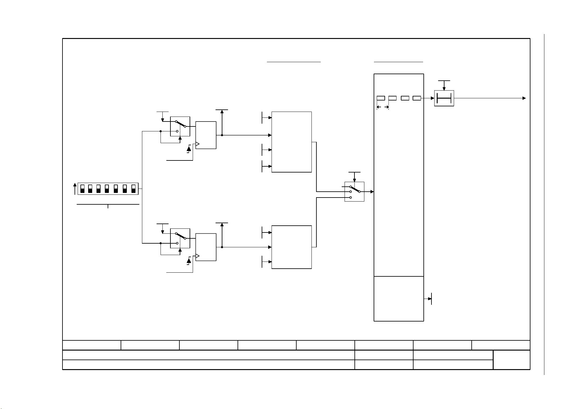
SINAMICS G120C
List Manual (LH13), 04/2014, A5E33840768B AA
361
3 Function diagrams
3.7 Communication, fieldbus interface (USS, MODBUS)
Fig. 3-34 9310 – Configuration, addresses and diagnostics
- 9310 -
Function diagram
87654321
fp_9310_97_66.vsd
Fieldbus Interface (USS, MODBUS)
G120C USS/MODBUS
07.04.2014 V4.7
Configuration, addresses and diagnostics
t
T0
Fieldbus configuration Monitoring functions
Cyclic telegrams from
the master
F01910 "Fieldbus IF: setpoint
timeout"
No telegrams from the master
Diagnostic parameters
Fieldbus t_monit
0 ... 1999999 [ms]
p2040 (100)
USS
configuration
MODBUS
configuration
Telegrams to the
master
Fieldbus times
p2024
Field bus USS PKW
p2023
Field bus USS PZD
p2022
Field bus baud
p2020
Field bus baud
p2020
No protocol
Field bus error
r2029
ON
1 2 4 8 16 32 64
>0
Significance
POWER ON
Actual address
Memory
SET
p2021
BUS ADDRESS
>0
POWER ON
Memory
SET
p2021
0
Field bus protocol
0 ... 4
p2030 (4)
1
2
Field bus address
p2021
Field bus address
p2021
1
All DIP switches to OFF
==> set the address using p2021
3 Function diagrams
3.7 Communication, fieldbus interface (USS, MODBUS)
SINAMICS G120C
362 List Manual (LH13), 04/2014, A5E33840768B AA
Fig. 3-35 9342 – STW1 control word interconnection
- 9342 -
Function diagram
87654321
fp_9342_97_62.vsd
Fieldbus Interface (USS, MODBUS)
G120C USS/MODBUS
07.04.2014 V4.7
STW1 control word interconnection
STW1.0
STW1.1
STW1.2
STW1.3
STW1.4
STW1.5
STW1.6
STW1.8
STW1.9
STW1.11
STW1.12
STW1.13
STW1.14
STW1.15
STW1.7
STW1.10
p0848[0] = r2090.2
p0852[0] = r2090.3
p2103[0] = r2090.7
-
-
p0854[0] = r2090.10
p1113[0] = r2090.11
-
p1035[0] = r2090.13
p1036[0] = r2090.14
-
p0840[0] = r2090.0
p0844[0] = r2090.1
[2501.3]
[2501.3]
[2501.3]
[2501.3]
[2501.3]
[2546.1]
-
-
[2501.3]
[2505.3]
-
[2505.3]
[2505.3]
-
[2501.3]
[2501.3]
[8060]
-
-
[2501]
[3040]
-
[3020]
[3020]
-
-
-
-
-
-
-
-
-
-
-
-
<1>
Signal targets for fieldbus STW1
Signal Meaning
Interconnection
parameters
[Function diagram]
internal control word
[Function diagram]
signal target
Inverted
0 = OFF1 (braking with ramp-function generator, then pulse suppression & ready for switching on)
= ON (pulses can be enabled)
1 = No OFF2 (enable is possible)
0 = OFF2 (immediate pulse suppression and switching on inhibited)
1 = No OFF3 (enable is possible)
0 = OFF3 (braking with the OFF3 ramp p1135, then pulse suppression and switching on inhibited)
1 = Enable operation (pulses can be enabled)
0 = Inhibit operation (suppress pulses)
1 = Ramp-function generator enable
0 = Inhibit ramp-function generator (set the ramp-function generator output to zero)
1 = Continue ramp-function generator
0 = Freezes the ramp-function generator
1 = Setpoint enable
0 = Inhibits the setpoint (the ramp-function generator input is set to zero)
= Acknowledge faults
Reserved
1 = Control via PLC
1 = Dir of rot reversal
1 = Motorized potentiometer, setpoint, raise
1 = Motorized potentiometer, setpoint, lower
Bit 10 in STW1 must be set to ensure that the drive accepts the process data.
Sequence control
Sequence control
Sequence control
Sequence control
[3070]
[3070]
[3070]
p1140[0] = r2090.4
p1141[0] = r2090.5
p1142[0] = r2090.6
<2>
-
-
-
-
-
The direction reversal can be locked. See p1110 and p1111.
Reserved
Reserved
Reserved
<1>
<2>
SINAMICS G120C
List Manual (LH13), 04/2014, A5E33840768B AA
363
3 Function diagrams
3.7 Communication, fieldbus interface (USS, MODBUS)
Fig. 3-36 9352 – ZSW1 status word interconnection
- 9352 -
Function diagram
87654321
fp_9352_97_62.vsd
Fieldbus Interface (USS, MODBUS)
G120C USS/MODBUS
07.04.2014 V4.7
ZSW1 status word interconnection
ZSW1.0
ZSW1.1
ZSW1.2
ZSW1.3
ZSW1.4
ZSW1.5
ZSW1.6
ZSW1.8
ZSW1.9
ZSW1.11
ZSW1.12
ZSW1.13
ZSW1.14
ZSW1.15
ZSW1.7
ZSW1.10
p2080[2] = r0899.2
p2080[3] = r2139.3
p2080[4] = r0899.4
p2080[5] = r0899.5
p2080[6] = r0899.6
p2080[7] = r2139.7
p2080[8] = r2197.7
p2080[9] = r0899.9
p2080[10] = r2199.1
p2080[11] = r1407.7
p2080[13] = r2135.14
p2080[15] = r2135.15
p2080[0] = r0899.0
p2080[1] = r0899.1
p2080[14] = r2197.3
[2503.7]
[2548.7]
[2503.7]
[2503.7]
[2503.7]
[2548.7]
[2534.7]
[2503.7]
[2536.7]
[2522.7]
[2548.7]
[2548.7]
[2503.7]
[2503.7]
[2534.7]
[8060]
[8065]
[8011]
[2503]
[8010]
[6060]
[8016]
[8014]
[8011]
-
-
-
-
-
-
-
-
-
-
-
-
-
Signal sources for fieldbus ZSW1
Signal Meaning
Interconnection
parameters
[Function diagram]
internal control word
[Function diagram]
signal target
Inverted
1 = Ready for switching on
1 = Ready for operation (DC link loaded, pulses inhibited)
1 = Operation enabled (drive follows n_set)
1 = Fault present
1 = No coast down active (OFF2 inactive)
1 = No quick stop active (OFF3 inactive)
1 = Switching on inhibited active
1 = Alarm present
1 = Speed setpoint - actual value deviation within tolerance t_off
1 = Control requested
1 = f or n comparison value reached/exceeded
1 = I, M, or P limit not reached
1 = Open holding brake
1 = No motor overtemperature alarm
1 = Motor rotates forwards (n_act 0)
1 = No alarm, thermal overload, power unit
The ZSW1 is generated using the binector-connector converter (BI: p2080[0...15], inversion: p2088[0].0...p2088[0].15).
The drive is ready to accept data.
Sequence control
p2080[12] = r0899.12 [2503.7] [2701]
<1>
Sequence control
Sequence control
Sequence control
Sequence control
Sequence control
<2>
<1>
<2>
3 Function diagrams
3.7 Communication, fieldbus interface (USS, MODBUS)
SINAMICS G120C
364 List Manual (LH13), 04/2014, A5E33840768B AA
Fig. 3-37 9360 – Receive telegram, free interconnection via BICO (p0922 = 999)
- 9360 -
Function diagram
87654321
fp_9360_97_05.vsd
Fieldbus Interface (USS, MODBUS)
G120C USS/MODBUS
07.04.2014 V4.7
Receive telegram, free interconnection via BICO (p0922 = 999)
<3>
<1>
Receive telegram
PZD receive word 1
PZD receive word 2
PZD receive word 3
PZD receive word 4
PZD receive word 5
PZD receive word 6
The following representation applies for words: 4000 hex = 100 %.
The reference variables p200x apply for the ongoing interconnection (100 % -> p200x).
The following applies for temperature values: 100 °C -> 100 % = 4000 hex, 0 °C -> 0 %.
Reference quantities for further
interconnection
p200x
Con/bin outp
r2094
r2050
PZD recv word
r2050
PZD recv word
Con/bin outp
r2094
Con/bin outp
r2095
Con/bin outp
r2095
PZD receive word 7
PZD receive word 8
r2050
PZD recv word
r2050
PZD recv word
Fieldbus
<3>
The receive word 1 must be used as control word (STW1) (due to bit 10 "control requested").
The preconfiguration with the speed setpoint is set automatically via p1000 = 6.
<2>
...
...
r2050
PZD recv word
r2050
PZD recv word
r2050
PZD recv word
r2050
PZD recv word
PZD1 recv bitw
r2090.0
PZD1 recv bitw
r2090
PZD2 recv bitw
r2091
PZD2 recv bitw
r2091
...
PZD3 recv bitw
r2092
PZD3 recv bitw
r2092
...
PZD4 recv bitw
r2093
PZD4 recv bitw
r2093
PZD receive word 9
PZD receive word 10
PZD receive word 11
PZD receive word 12
r2050
PZD recv word
r2050
PZD recv word
r2050
PZD recv word
r2050
PZD recv word
.15
.0
.15
.15
.15
.0
.0
[0]
[1]
[2]
[3]
[4]
[5]
[6]
[7]
[8]
[9]
[10]
[11]
.0
.15
.0
.15
<1>
<2>
SINAMICS G120C
List Manual (LH13), 04/2014, A5E33840768B AA
365
3 Function diagrams
3.7 Communication, fieldbus interface (USS, MODBUS)
Fig. 3-38 9370 – Send telegram, free interconnection via BICO (p0922 = 999)
- 9370 -
Function diagram
87654321
fp_9370_97_62.vsd
Fieldbus Interface (USS, MODBUS)
G120C USS/MODBUS
07.04.2014 V4.7
Send telegram, free interconnection via BICO (p0922 = 999)
...
Reference quantities for
further interconnection
p200x
The send word 1 must be used as status word (ZSW1).
Physical word values are inserted in the telegram as referenced variables. p200x apply as reference variables (telegram contents = 4000
hex, if the input variable has the value p200x).
The following applies for temperature values: 100 °C -> 100 % = 4000
PZD send word 1
PZD send word 2
PZD send word 3
PZD send word 4
PZD send word 5
PZD send word 6
PZD send word 7
PZD send word 8
Send telegram
Diag send word
r2053
[0 … 7]
PZD send word
(0)
p2051[0]
PZD send word
(0)
p2051[1]
PZD send word
(0)
p2051[2]
PZD send word
(0)
p2051[3]
PZD send word
(0)
p2051[4]
PZD send word
(0)
p2051[5]
PZD send word
(0)
p2051[6]
PZD send word
(0)
p2051[7]
Fieldbus
The preconfiguration with the speed setpoint is set automatically via p1000 = 6.
<1>
<2>
<3>
<3>
<1>
<1>
<2>

3 Function diagrams
3.8 Internal control/status words
SINAMICS G120C
366 List Manual (LH13), 04/2014, A5E33840768B AA
3.8 Internal control/status words
Function diagrams
2501 – Control word, sequence control 367
2503 – Status word, sequence control 368
2505 – Control word, setpoint channel 369
2510 – Status word 1 (r0052) 370
2511 – Status word 2 (r0053) 371
2512 – Control word 1 (r0054) 372
2513 – Control word 2 (r0055) 373
2522 – Status word, speed controller 374
2526 – Status word, closed-loop control 375
2530 – Status word, closed-loop current control 376
2534 – Status word, monitoring functions 1 377
2536 – Status word, monitoring functions 2 378
2537 – Status word, monitoring functions 3 379
2546 – Control word, faults/alarms 380
2548 – Status word, faults/alarms 1 and 2 381
2610 – Sequence control - Sequencer 382
2634 – Sequence control - Missing enable signals 383
SINAMICS G120C
List Manual (LH13), 04/2014, A5E33840768B AA
367
3 Function diagrams
3.8 Internal control/status words
Fig. 3-39 2501 – Control word, sequence control
- 2501 -
Function diagram
87654321
fp_2501_97_05.vsd
Internal control/status words
SINAMICS G120C
07.04.2014 V4.7
Control word, sequence control
11
12
13
14
15
PROFIdrive-Bit
<1>
10
7
6
5
4
3
2
1
0
<2>
<2>
<2>
r0898.0
r0898.1
r0898.2
r0898.3
r0898.10
9
8 r0898.8
r0898.9
<3>
<3>
<3>
<3>
<3>
<3>
<3>
<3>
<1>
(1)
OFF2 S_src 1
p0844 [C]
(1)
OFF2 S_src 2
p0845 [C]
(1)
OFF3 S_src 1
p0848 [C]
(1)
OFF3 S_src 2
p0849 [C]
Bit 10 in STW1 must be set to ensure
that the drive accepts the process
data.
PROFIdrive interconnection for CDS0:
For PROFIdrive standard telegrams, the upper inputs are connected with
PROFIdrive-STW1 [2420].
When the master control is retrieved, predefined by STARTER or AOP30.
Control word sequence control (r0898)
= ON
0 = OFF1 active
1 = Operating condition, no coast down active (OFF2 inactive)
0 = OFF2 active
1 = Enable operation
1 = Operating condition, no quick stop active (OFF3 inactive)
0 = OFF3 active
1 = Enable ramp-function generator
1 = Continue ramp-function generator
1 = Enable speed setpoint
1 = Jog 1
1 = Jog 2
1 = Control via PLC
Reserved
Reserved
Reserved
1 = Speed controller enable
To the control unit
To the control unit
To the control unit
To the control unit
To jog [3030.6]
To jog [3030.6]
STW seq_ctrl
r0898
r0898
Bit
No.
(722.0)
ON / OFF (OFF1)
p0840 [C]
(1)
Operation enable
p0852 [C]
(1)
Master ctrl by PLC
p0854 [C]
(0)
Jog bit 0
p1055 [C]
(0)
Jog bit 1
p1056 [C]
1 = Command open brake
1 = Command close brake
r0898.7
To the brake control [2701.4]
r0898.14
To the brake control [2701.4]
r0898.12
To the brake control [2701.4]
To the torque setpoint [6060.4]
<3>
(0)
Uncond open brake
p0855 [C]
<3>
(0)
Uncond close brake
p0858 [C]
<3>
(1)
n_ctrl enable
p0856 [C]
r2090.4 with PROFIBUS or 1
r2090.5 with PROFIBUS or 1
r2090.6 with PROFIBUS or 1
r0898.4
r0898.5
r0898.6
To the setpoint channel [3070.7]
To the setpoint channel [3070.1]
To the setpoint channel [3070.1]
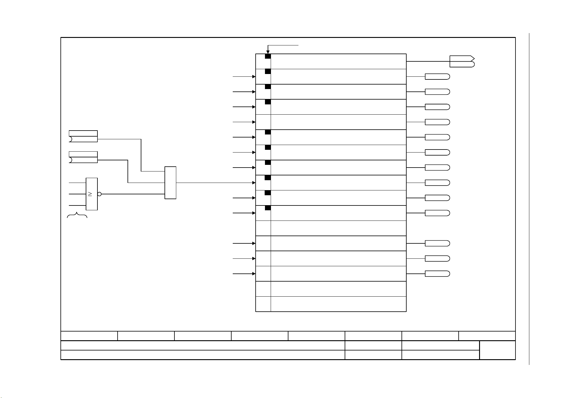
3 Function diagrams
3.8 Internal control/status words
SINAMICS G120C
368 List Manual (LH13), 04/2014, A5E33840768B AA
Fig. 3-40 2503 – Status word, sequence control
- 2503 -
Function diagram
87654321
fp_2503_97_05.vsd
Internal control/status words
SINAMICS G120C
07.04.2014 V4.7
Status word, sequence control
11
12
13
14
15
PROFIdrive-Bit
10
9
8
7
6
5
4
3
0
1
2
r0899.0
r0899.1
r0899.4
r0899.5
r0899.11
r0899.2
r0899.6
r0899.9
r0899.3
r0899.7
r0899.8
1
&
(1)
OFF2 S_src 2
p0845 [C]
(1)
OFF3 S_src 2
p0849 [C]
OFF1
OFF2
OFF3
Enable internal
missing or
fault with
this reaction
Bit 9 = 1 --> Ready to exchange process data
From the Control Unit
The drive is ready to accept data.
Status word sequence control (r0899)
1 = Ready for switch on
1 = Ready (DC link loaded, pulses inhibited)
1 = Operation enabled (drive follows n_set)
1 = Jog active
1 = No coast down active (OFF2 inactive)
1 = No quick stop active (OFF3 inactive)
1 = Switching on inhibited active
1 = Drive ready
1 = Controller enable
1 = Control requested
Reserved
1 = Pulses enabled
Reserved
Reserved
ZSW seq_ctrl
r0899
r0899
Bit No.
1 = Command close holding brake
1 = Open holding brake
<1>
From the brake control [2701.8]
From the brake control [2701.8]
r0899.12
r0899.13
<1>
From the Control Unit
From the Control Unit
From the Control Unit
From the Control Unit
From the Control Unit
From the Control Unit
From the Control Unit
From the Control Unit
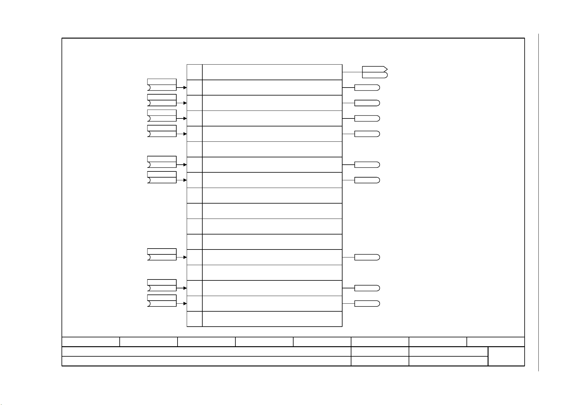
SINAMICS G120C
List Manual (LH13), 04/2014, A5E33840768B AA
369
3 Function diagrams
3.8 Internal control/status words
Fig. 3-41 2505 – Control word, setpoint channel
- 2505 -
Function diagram
87654321
fp_2505_97_05.vsd
Internal control/status words
SINAMICS G120C
07.04.2014 V4.7
Control word, setpoint channel
11
12
13
14
15
9
10
8
7
6
5
4
3
2
1
0
r1198.3
r1198.5
r1198.11
r1198.13
r1198.14
r1198.2
r1198.1
r1198.0
(0)
n_set_fixed Bit 0
p1020 [C]
(0)
n_set_fixed Bit 1
p1021 [C]
(0)
n_set_fixed Bit 2
p1022 [C]
(0)
n_set_fixed Bit 3
p1023 [C]
(0)
Mop raise
p1035 [C]
(0)
Mop lower
p1036 [C]
Control word setpoint channel (r1198)
1 = Fixed setpoint, bit 0
1 = Fixed setpoint, bit 1
1 = Fixed setpoint, bit 2
1 = Fixed setpoint, bit 3
Reserved
1 = Inhibit negative direction of rotation
1 = Inhibit positive direction of rotation
Reserved
Reserved
Reserved
Reserved
1 = Setpoint inversion
Reserved
1 = Motorized potentiometer, raise
1 = Motorized potentiometer, lower
1 = Bypass ramp-function generator
To fixed speed setpoints [3010.2]
To fixed speed setpoints [3010.2]
To fixed speed setpoints [3010.2]
To fixed speed setpoints [3010.2]
To direction of rotation limiting and
direction of rotation reversal [3040.3]
To direction of rotation limiting and
direction of rotation reversal [3040.2]
To the motorized potentiometer [3020.1]
To the motorized potentiometer [3020.1]
STW setpoint chan
r1198
r1198
Bit No.
(0)
Inhib neg dir
p1110 [C]
(722.1)
Setp inv
p1113 [C]
r1198.6
To direction of rotation limiting and
direction of rotation reversal [3040.3]
(0)
Inhib pos dir
p1111 [C]
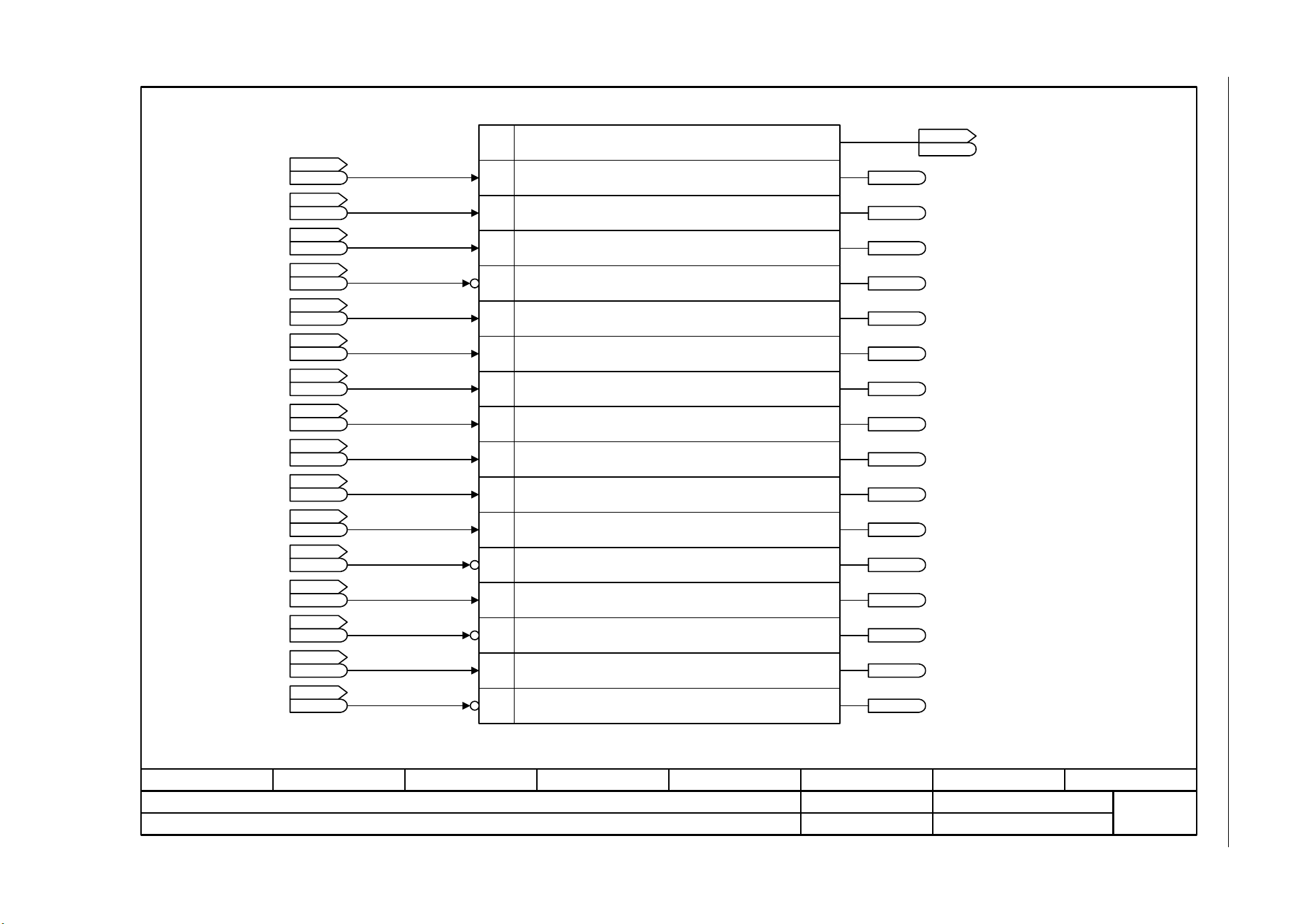
3 Function diagrams
3.8 Internal control/status words
SINAMICS G120C
370 List Manual (LH13), 04/2014, A5E33840768B AA
Fig. 3-42 2510 – Status word 1 (r0052)
- 2510 -
Function diagram
87654321
fp_2510_97_05.vsd
Internal control/status words
SINAMICS G120C
07.04.2014 V4.7
Status word 1 (r0052)
1
2
3
4
5
6
7
8
9
10
11
12
13
14
15
0
ZSW 1
r0052
r0052
1 = Ready for switch on
1 = Ready (DC link loaded, pulses inhibited)
1 = Operation enabled (voltage at output terminals)
1 = Fault present (pulses inhibited)
0 = Coast down active (OFF2 active)
0 = Quick stop active (OFF3 active)
1 = Switching on inhibited active
1 = Alarm present
0 = Deviation setpoint/actual speed
1 = Control request
1 = Maximum speed reached (f_act >= p1082 (f_max))
0 = f_act < p1082 (f_max)
0 = I,M,P limit reached
0 = Alarm motor overtemperature
1 = Motor rotates forwards
0 = Alarm drive converter overload
Signal is inverted if connected to a Digital
Output.
Bit No. Status word 1 (r0052)
ZSW seq_ctrl
r0899
r0899
.0
ZSW fault/alarm 1
r2139
r2139
ZSW seq_ctrl
r0899
r0899
ZSW seq_ctrl
r0899
r0899
ZSW seq_ctrl
r0899
r0899
ZSW seq_ctrl
r0899
r0899
ZSW seq_ctrl
r0899
r0899
ZSW fault/alarm 1
r2139
r2139
ZSW monitor 1
r2197
r2197
ZSW seq_ctrl
r0899
r0899
ZSW monitor 1
r2197
r2197
ZSW cl-loop ctrl
r0056
r0056
ZSW fault/alarm 2
r2135
r2135
ZSW monitor 1
r2197
r2197
ZSW fault/alarm 2
r2135
r2135
.1
.2
.3
.4
.5
.6
.7
.7
.7
.6
.13
.14
.3
.15
r0052.0
r0052.1
r0052.4
r0052.5
r0052.11
r0052.2
r0052.6
r0052.9
r0052.13
r0052.14
r0052.15
r0052.3
r0052.7
r0052.8
r0052.10
[2503.7]
[2503.7]
[2503.7]
[2548.7]
[2503.7]
[2503.7]
[2503.7]
[2548.7]
[2534.7]
[2503.7]
[2534.7]
[2526.7]
[2548.7]
[2534.7]
[2548.7]
1 = Motor holding brake open
ZSW seq_ctrl
r0899
r0899
.12
[2701.8]
r0052.12
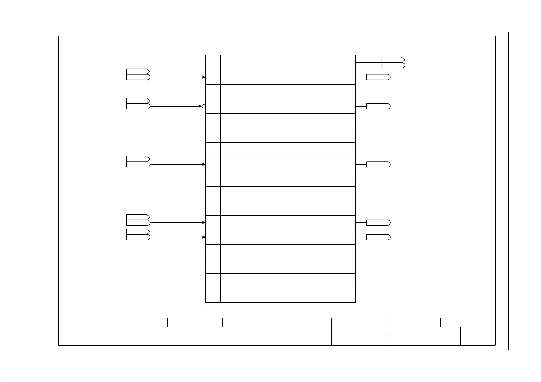
SINAMICS G120C
List Manual (LH13), 04/2014, A5E33840768B AA
371
3 Function diagrams
3.8 Internal control/status words
Fig. 3-43 2511 – Status word 2 (r0053)
- 2511 -
Function diagram
87654321
fp_2511_97_05.vsd
Internal control/status words
SINAMICS G120C
07.04.2014 V4.7
Status word 2 (r0053)
1
2
3
4
5
6
7
8
9
10
11
12
13
14
15
0
ZSW 2
r0053
r0053
1 = DC braking active
Bit No. Status word 2 (r0053)
Reserved
1 = |n_act| > p1080 (n_min)
Reserved
Reserved
Reserved
1 = |n_act| >= r1119 (n_set)
Reserved
Reserved
Reserved
1 = Technology controller output at the lower limit
1 = Technology controller output at the upper limit
Reserved
Reserved
DCBRK ZSW
r1239
r1239
Reserved
Reserved
ZSW monitor 1
r2197
r2197
ZSW monitor 1
r2197
r2197
.8
.0
.4
Tec_ctrl status
r2349
r2349
Tec_ctrl status
r2349
r2349
.10
.11
r0053.0
r0053.11
r0053.2
r0053.6
r0053.10
[7017.5]
[2534.7]
[2534.7]
[7958.7]
[7958.7]
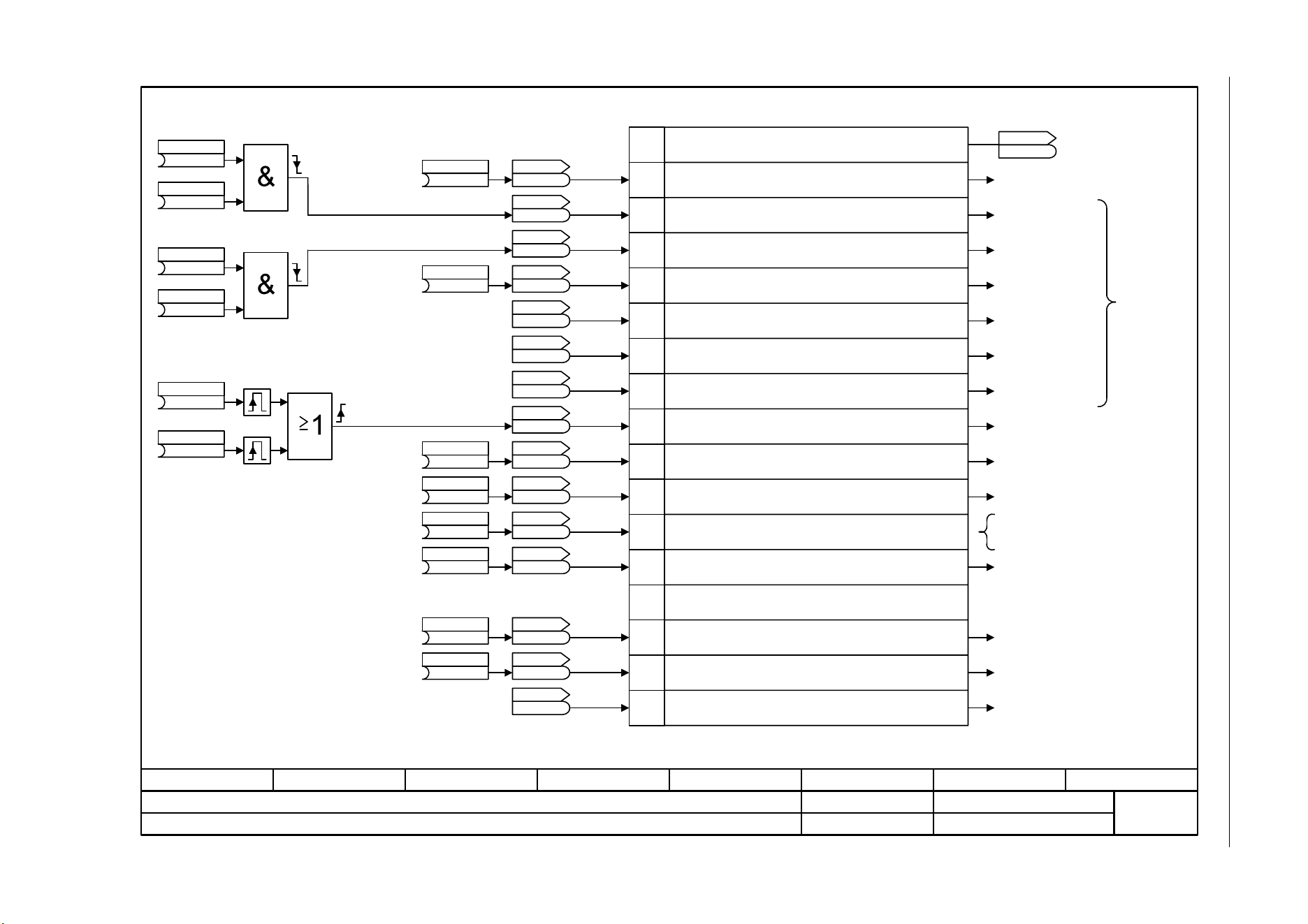
3 Function diagrams
3.8 Internal control/status words
SINAMICS G120C
372 List Manual (LH13), 04/2014, A5E33840768B AA
Fig. 3-44 2512 – Control word 1 (r0054)
- 2512 -
Function diagram
87654321
fp_2512_97_05.vsd
Internal control/status words
SINAMICS G120C
07.04.2014 V4.7
Control word 1 (r0054)
1
2
3
4
5
6
7
8
9
10
11
12
13
14
15
0
Sequence control
Setpoint channel
Setpoint channel
Setpoint channel
Setpoint channel
Sequence control
Setpoint channel
Sequence control
Sequence control
Setpoint channel
Setpoint channel
Setpoint channel
Sequence control
Sequence control
Setpoint channel
Sequence control
Sequence control
Setpoint channel
All bits = 1 -->
drive runs
Bit 10 in STW1 must be set to ensure
that the drive accepts the process
data.
Bit No. Control word 1 (r0054)
0 = OFF1, Shutdown via ramp, followed by pulse inhibit
1 = ON, operating condition (edge-controlled)
0 = OFF2: Electrical stop, pulse inhibit, motor coasts down
1 = Operating condition
0 = OFF3: Quick stop
1 = Operating condition
1 = Operation enable
1 = Ramp-function generator enable
1 = Continue ramp-function generator
1 = Speed setpoint enable
1 = Acknowledge fault
1 = Jog bit 0
1 = Jog bit 1
1 = Master ctrl by PLC
1 = Directions reversal (setpoint)
Reserved
1 = Motorized potentiometer raise
1 = Motorized potentiometer lower
1 = CDS bit 0
STW 1
r0054
r0054
STW seq_ctrl
r0898
r0898
.0
[2501.7]
[2501.7]
[2501.7]
[2501.7]
[2501.7]
[2501.7]
[2501.7]
[2546.7]
[2501.7]
[2501.7]
[2501.7]
[2505.7]
[2505.7]
[2505.7]
[8560.7]
(1)
OFF2 S_src 1
p0844 [C]
(1)
OFF2 S_src 2
p0845 [C]
(1)
OFF3 S_src 1
p0848 [C]
(1)
OFF3 S_src 2
p0849 [C]
(722.0)
ON / OFF (OFF1)
p0840 [C]
(1)
Operation enable
p0852 [C]
(1)
Master ctrl by PLC
p0854 [C]
(0)
Jog bit 0
p1055 [C]
(0)
Jog bit 1
p1056 [C]
r0898.1
r0898
r0898.2
r0898
r0898.3
r0898
r0898.4
r0898
r0898.5
r0898
r0898.6
r0898
r2138.7
r2138
r0898.8
r0898
r0898.9
r0898
r0898.10
r0898
r1198.11
r1198
r1198.13
r1198
r1198.14
r1198
r0836.0
r0836
(0)
Mop raise
p1035 [C]
(0)
Mop lower
p1036 [C]
(722.1)
Setp inv
p1113 [C]
Pulse generator
(722.2)
1. Acknowledge
p2103 [C]
(0)
2. Acknowledge
p2104 [C]
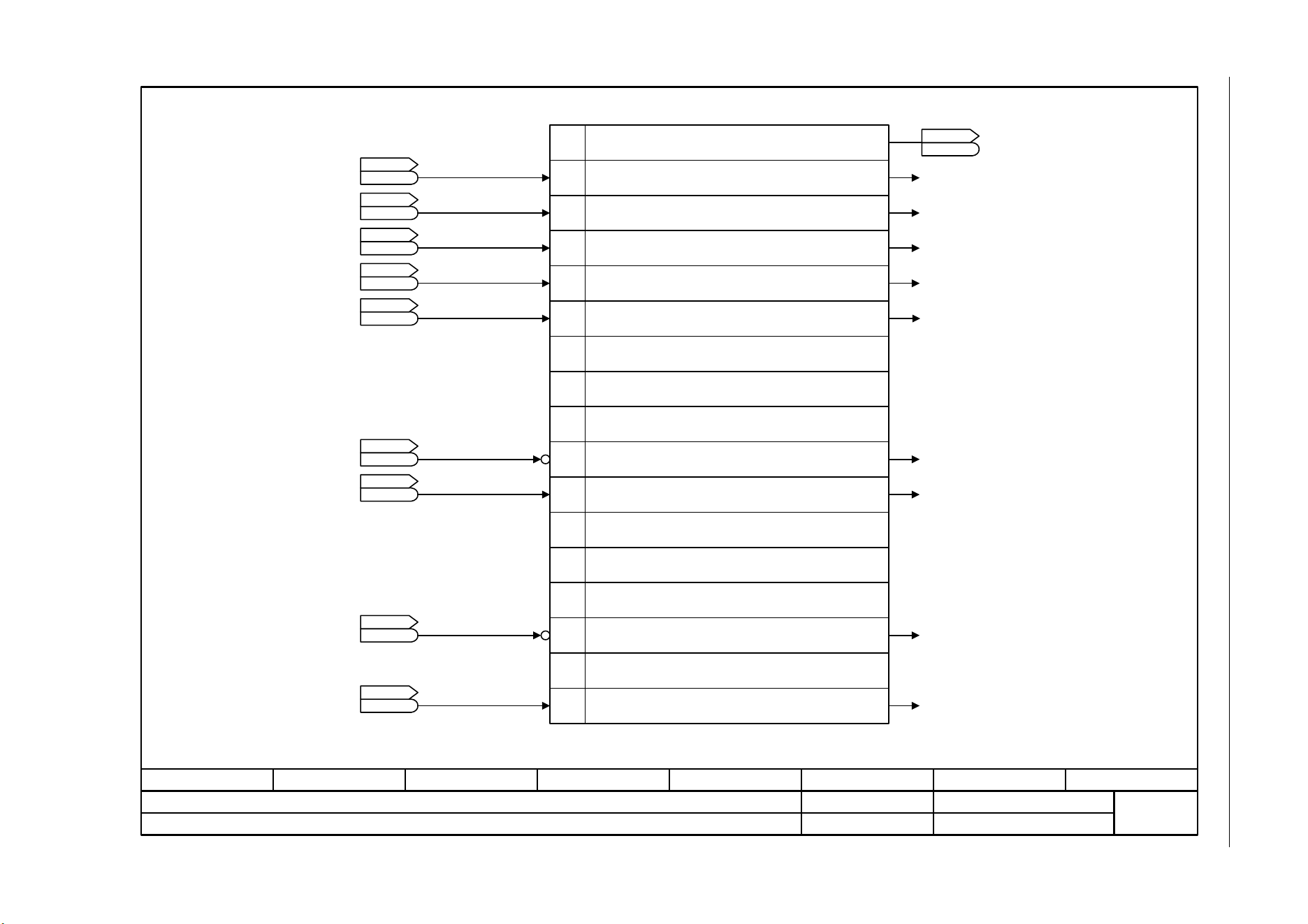
SINAMICS G120C
List Manual (LH13), 04/2014, A5E33840768B AA
373
3 Function diagrams
3.8 Internal control/status words
Fig. 3-45 2513 – Control word 2 (r0055)
- 2513 -
Function diagram
87654321
fp_2513_97_05.vsd
Internal control/status words
SINAMICS G120C
07.04.2014 V4.7
Control word 2 (r0055)
1
2
3
4
5
6
7
8
9
10
11
12
13
14
15
0
Bit No. Control word 2 (r0055)
1 = Fixed setp bit 0
1 = Fixed setp bit 1
1 = Fixed setp bit 2
1 = Fixed setp bit 3
Reserved
Reserved
1 = Technology controller enable
1 = DC brake enable
Reserved
Reserved
Reserved
0 = External fault 1 (F07860)
Reserved
1 = CDS bit 1
Suppl STW
r0055
r0055
Sequence control
DC braking control
Technology controller
Fixed frequencies
Fixed frequencies
Fixed frequencies
Fixed frequencies
STW setpoint chan
r1198
r1198
.0
[2505.7]
STW setpoint chan
r1198
r1198
.1
[2505.7]
STW setpoint chan
r1198
r1198
.2
[2505.7]
STW setpoint chan
r1198
r1198
.3
[2505.7]
Tec_ctrl status
r2349
r2349
.0
[7958.6]
DCBRK ZSW
r1239
r1239
.11
[7017.7]
STW fault/alarm
r2138
r2138
.13
[2546.7]
Reserved
1 = DDS select. bit 0
CDS selected
r0836
r0836
.1 Sequence control
[8560.7]
DDS selected
r0837
r0837
.0
[8565.6]
Sequence control
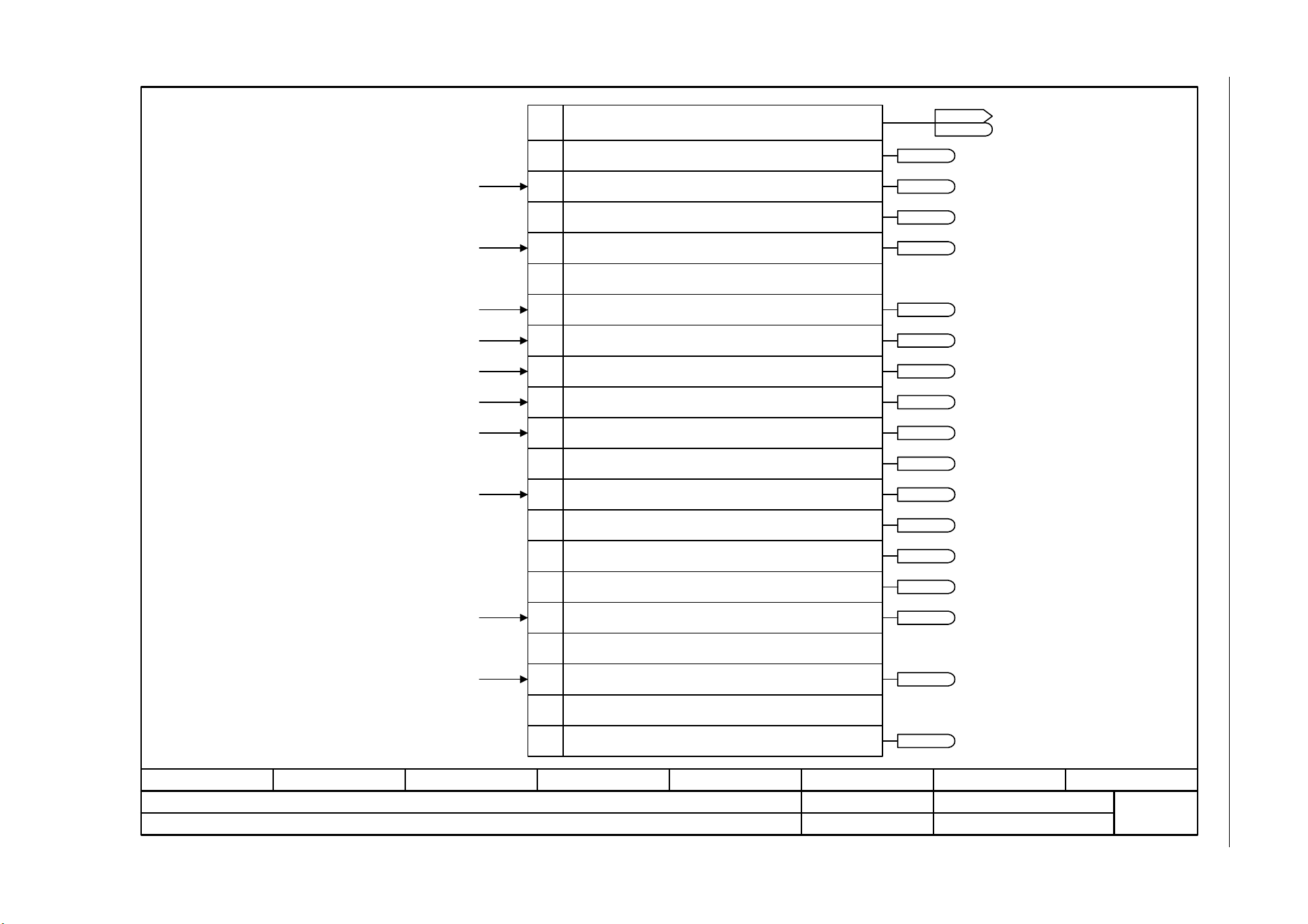
3 Function diagrams
3.8 Internal control/status words
SINAMICS G120C
374 List Manual (LH13), 04/2014, A5E33840768B AA
Fig. 3-46 2522 – Status word, speed controller
- 2522 -
Function diagram
87654321
fp_2522_97_05.vsd
Internal control/status words
SINAMICS G120C
07.04.2014 V4.7
Status word, speed controller (r1407)
1
2
3
4
5
6
7
8
9
10
11
0
12
13
14
15
r1407.8
r1407.9
r1407.11
r1407.1
r1407.7
r1407.10
r1407.11
r1407.5
r1407.6
r1407.3
r1407.12
r1407.13
r1407.0
From the changeover, closed-loop control types
From the control unit
Status word speed controller (r1407)
Bit No.
1 = U/f control active
1 = Sensorless operation active
1 = Closed-loop speed control active
1 = Speed controller, I component held
1 = Speed controller, I component set
1 = Torque limit reached
1 = Torque limiting, upper, active
1 = Torque limiting, lower, active
1 = Droop enabled
1 = Speed setpoint limited
1 = Ramp-function generator set
1 = Sensorless operation due to a fault
1 = I/f control active
1 = Torque limit reached (without pre-control)
Ramp-function generator tracking [1550.7]
Speed controller [6040.4]
Motor locked/stalled [8012.5]
From the speed setpoint [6030.3]
From the torque setpoint [6060.4], [6060.7]
From the torque setpoint [6060.5]
From the speed controller [6040.7]
From the speed controller [6040.7]
ZSW n_ctrl
r1407
r1407
Reserved
From the torque setpoint [6060.5]
0 = Torque control active
16
17
Reserved
1 = Speed limiting control active
From the speed limiting [6640.8]
r1407.17
r1407.15
r1407.14
From the torque setpoint [6060.5]
r1407.2
...
23
Reserved
1 = Acceleration model switched on
r1407.23
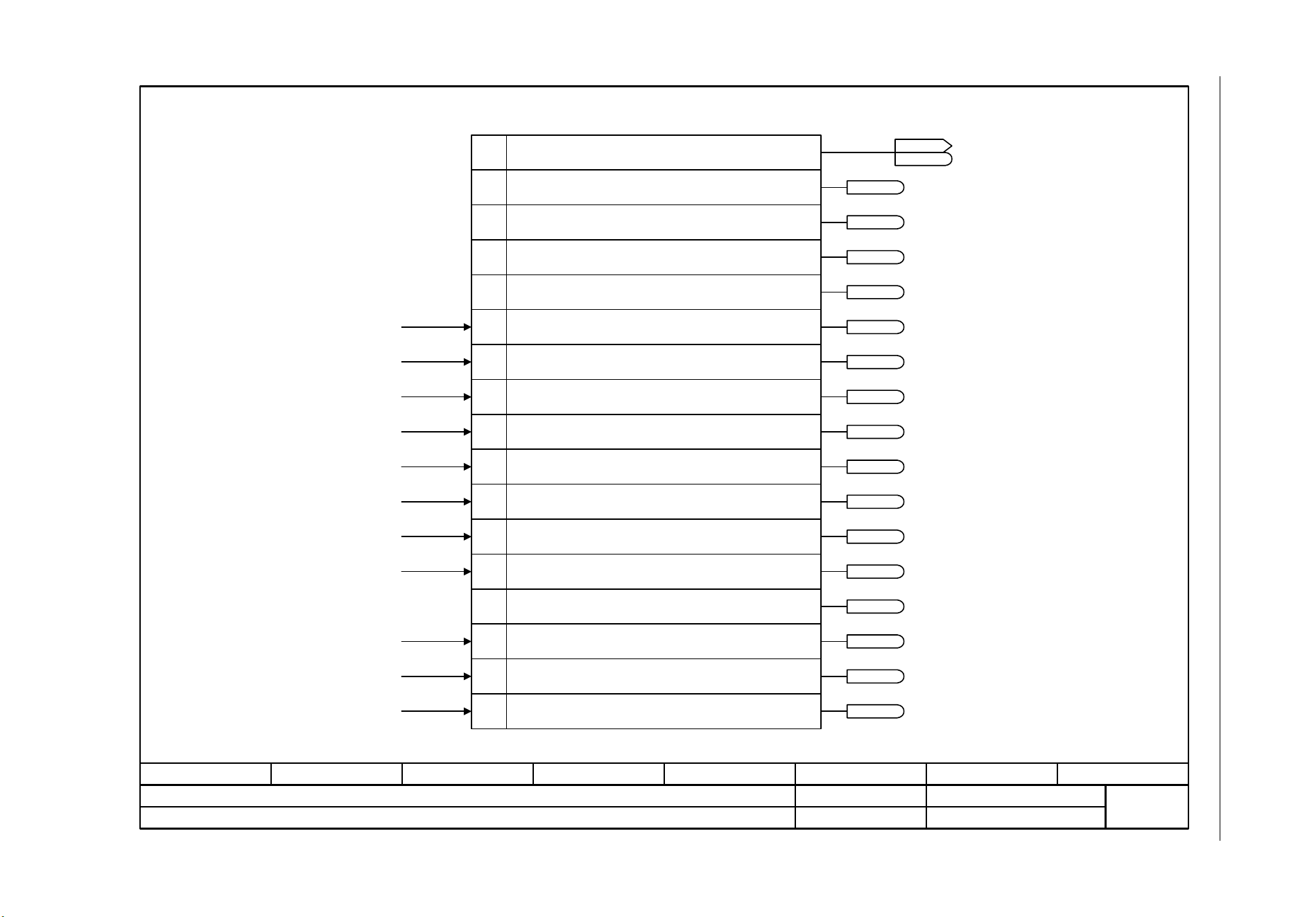
SINAMICS G120C
List Manual (LH13), 04/2014, A5E33840768B AA
375
3 Function diagrams
3.8 Internal control/status words
Fig. 3-47 2526 – Status word, closed-loop control
- 2526 -
Function diagram
87654321
fp_2526_97_66.vsd
Internal control/status words
SINAMICS G120C
07.04.2014 V4.7
Status word, closed-loop control (r0056)
1
2
4
0
7
8
9
11
14
15
[6722.6]
[6722.3]
[6714.8]
3
5
6
12
13
10[6310.8]
<1>
<1>
<1>
<1>
<1>
[6060.8]
[6710.1]
[8012.5]
Only for U/f control.
Status word closed-loop control (r0056)Bit No.
1 = Initialization completed
1 = De-magnetization completed
1 = Pulse enable available
1 = Soft starting available
1 = Magnetization completed
1 = Acceleration voltage active
1 = Frequency, negative
1 = Field weakening active
1 = Voltage limit active
1 = Slip limiting active
1 = Frequency limit active
1 = Current limiting controller, voltage output active
1 = Current/torque limiting active
1 = Vdc_max controller active
1 = Vdc_min controller active
ZSW cl-loop ctrl
r0056
r0056
1 = Starting boost active
r0056.0
r0056.1
r0056.4
r0056.5
r0056.11
r0056.12
r0056.2
r0056.6
r0056.9
r0056.13
r0056.14
r0056.15
r0056.3
r0056.7
r0056.8
r0056.10
<1>
[6030.6], [6710.1]
[6730.4], [6731.4]
[6730.4], [6731.4]
[2510.1], [8012.5]
[2701.1]
[6301.2]
[6301.4]
[6710.5]
[6220.8], [6320.8]
[6220.8], [6320.8]
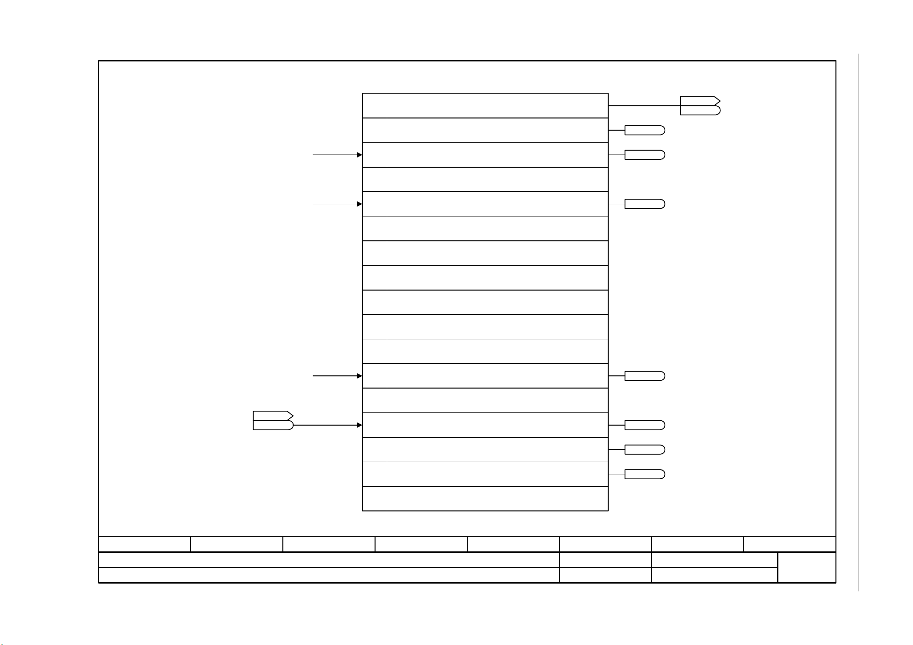
3 Function diagrams
3.8 Internal control/status words
SINAMICS G120C
376 List Manual (LH13), 04/2014, A5E33840768B AA
Fig. 3-48 2530 – Status word, closed-loop current control
- 2530 -
Function diagram
87654321
fp_2530_97_64.vsd
Internal control/status words
SINAMICS G120C
07.04.2014 V4.7
Status word, closed-loop current control
1
2
0
[6714.5]
[6714.8] 3
4
5
6
7
8
9
10
11
12
13
14
15
[6730.3]
Status word current control (r1408)Bit No.
1 = Closed-loop current control active
1 = Id controller I comp. limitation
Reserved
1 = Voltage limitation
1 = Speed adaptation limitation
1 = Motor stalled
Reserved
ZSW I_ctrl
r1408
r1408
Reserved
Reserved
Reserved
Reserved
Reserved
Reserved
r1408.0
r1408.1
r1408.12
r1408.3
r1408.10
ZSW monitor 2
r2198
r2198
.7
[2536.7]
1 = Separately-excited synchronous motor is excited
1 = Current model FEM: Magnetizing excitation current set to 0
r1408.14
r1408.13
Reserved
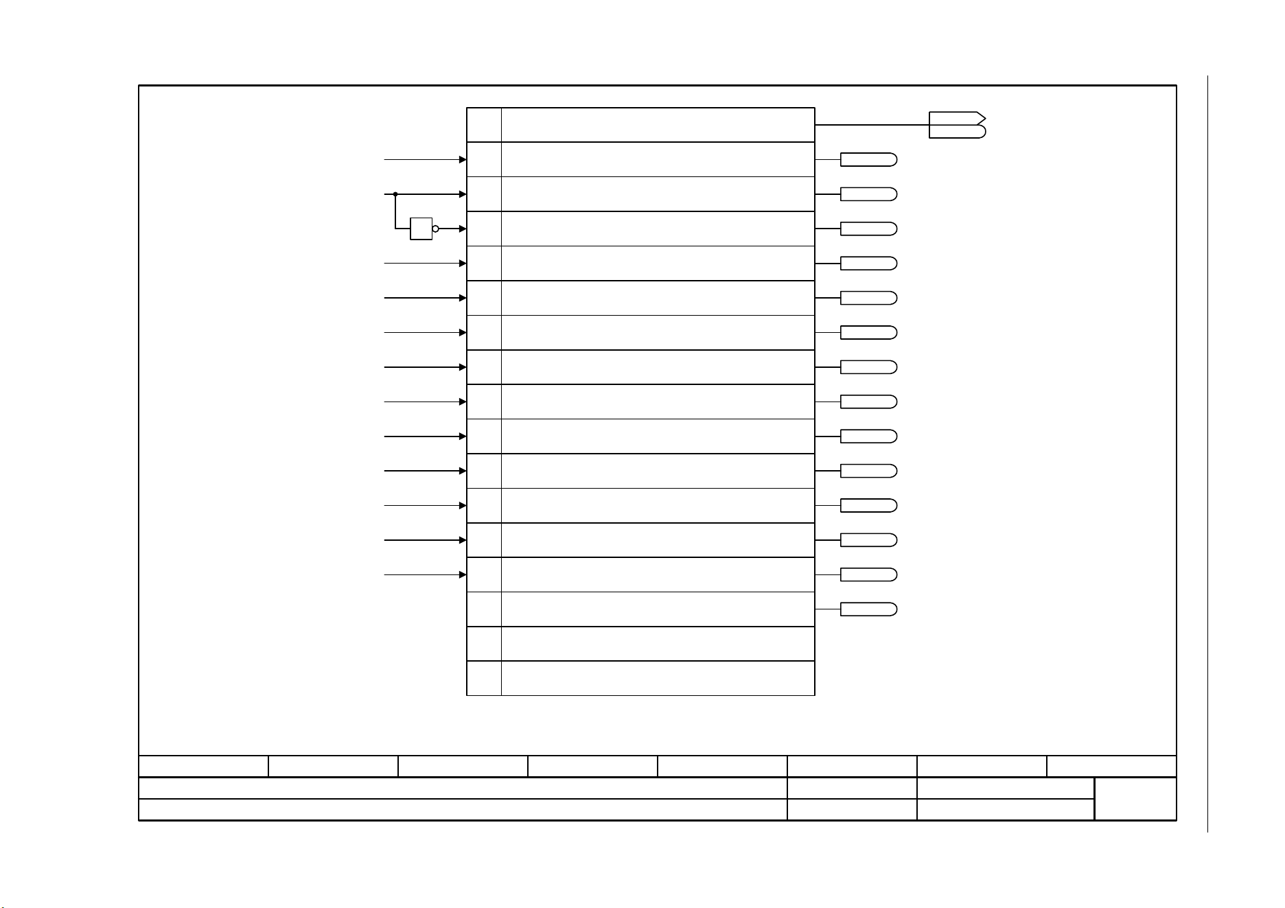
SINAMICS G120C
List Manual (LH13), 04/2014, A5E33840768B AA
377
3 Function diagrams
3.8 Internal control/status words
Fig. 3-49 2534 – Status word, monitoring functions 1
- 2534 -
Function diagram
87654321
fp_2534_97_05.vsd
Internal control/status words
SINAMICS G120C
07.04.2014 V4.7
Status word, monitoring functions 1
9
10
8
7
6
5
4
3
2
1
0
1
ZSW monitor 1
r2197
r2197
From speed signals
From speed signals
From speed signals
From speed signals
Status word, monitoring functions 1 (r2197)Bit No.
1 = |n_act| <= n_min p1080
1 = |n_act| >= n_set
1 = |n_act| <= n_standstill p1226
1 = I_act >= I_threshold p2170
1 = Vdc_act <= Vdc_threshold p2172
1 = Vdc_act > Vdc_threshold p2172
1 = |n_act| <= speed threshold value 2 (p2155)
1 = |n_act| > speed threshold value 2 (p2155)
1 = n_act >= 0
1 = |n_act| > n_max
1 = Speed setpoint - actual value deviation within tolerance t_off
n_act = smoothed speed actual value r2169 [8010.2].
11
12
1 = Load missing
1 = |n_act| > n_max (with delay)
From extended signals
From extended signals
From extended signals
From extended signals
From extended signals
From extended signals
From extended signals
From extended signals
13
14
15
Reserved
Reserved
r2197.0
r2197.1
r2197.4
r2197.5
r2197.11
r2197.12
r2197.2
r2197.6
r2197.9
r2197.3
r2197.7
r2197.8
r2197.10
[8020.8]
[8010.8]
[8011.8]
[8020.8]
[8020.8]
[8010.8]
[8011.8]
[8020.8]
[8020.8]
[8020.8]
[8020.8]
[8021.8]
1 = |n_act| > n_max
[2510.2], [8021.1]
[2511.2]
[2511.2]
[2511.2]
[2511.2]
[2511.2]
[2511.2]
[2511.2]
[2511.2]
[2510.2]
[2510.2]
(F07901)
r2197.13
<1>
<1>
<1>

3 Function diagrams
3.8 Internal control/status words
SINAMICS G120C
378 List Manual (LH13), 04/2014, A5E33840768B AA
Fig. 3-50 2536 – Status word, monitoring functions 2
- 2536 -
Function diagram
87654321
fp_2536_97_63.vsd
Internal control/status words
SINAMICS G120C
07.04.2014 V4.7
Status word, monitoring functions 2
11
12
13
14
15
9
10
8
6
5
4
3
2
1
0
7
From speed signals
From speed signals
From torque messages, motor locked/stalled
From torque messages, motor locked/stalled
From torque messages, motor locked/stalled
From load monitoring
From load monitoring
Status word, monitoring functions 2 (r2198)Bit No.
1 = |n_act| <= speed threshold 5
1 = |n_act| > speed threshold 5
1 = |n_act| <= speed threshold 6
1 = |n_act| > speed threshold 6
1 = |I_act| < I_threshold p2170
1 = |M_act| > torque threshold 1 and n_set reached
1 = |M_act| > torque threshold 1
Reserved
Reserved
1 = |n_set| < p2161
1 = n_set > 0
1 = Motor blocked
1 = Motor stalled
1 = Load monitoring signals an alarm
1 = Load monitoring signals a fault
1 = |M_set| < torque threshold 1 (p2174)
ZSW monitor 2
r2198
r2198
From extended signals
From extended signals
From extended signals
From extended signals
From extended signals
From extended signals
From extended signals
r2198.0
r2198.1
r2198.4
r2198.5
r2198.11
r2198.12
r2198.2
r2198.6
r2198.9
r2198.13
r2198.3
r2198.7
r2198.8
r2198.10
[8021.8]
[8011.8]
[8011.8]
[8012.8]
[8012.8]
[8012.3]
[8013.8]
[8013.8]
[8021.8]
[8021.8]
[8020.8]
[8021.8]
[8021.8]
[8021.8]
[2530.2]
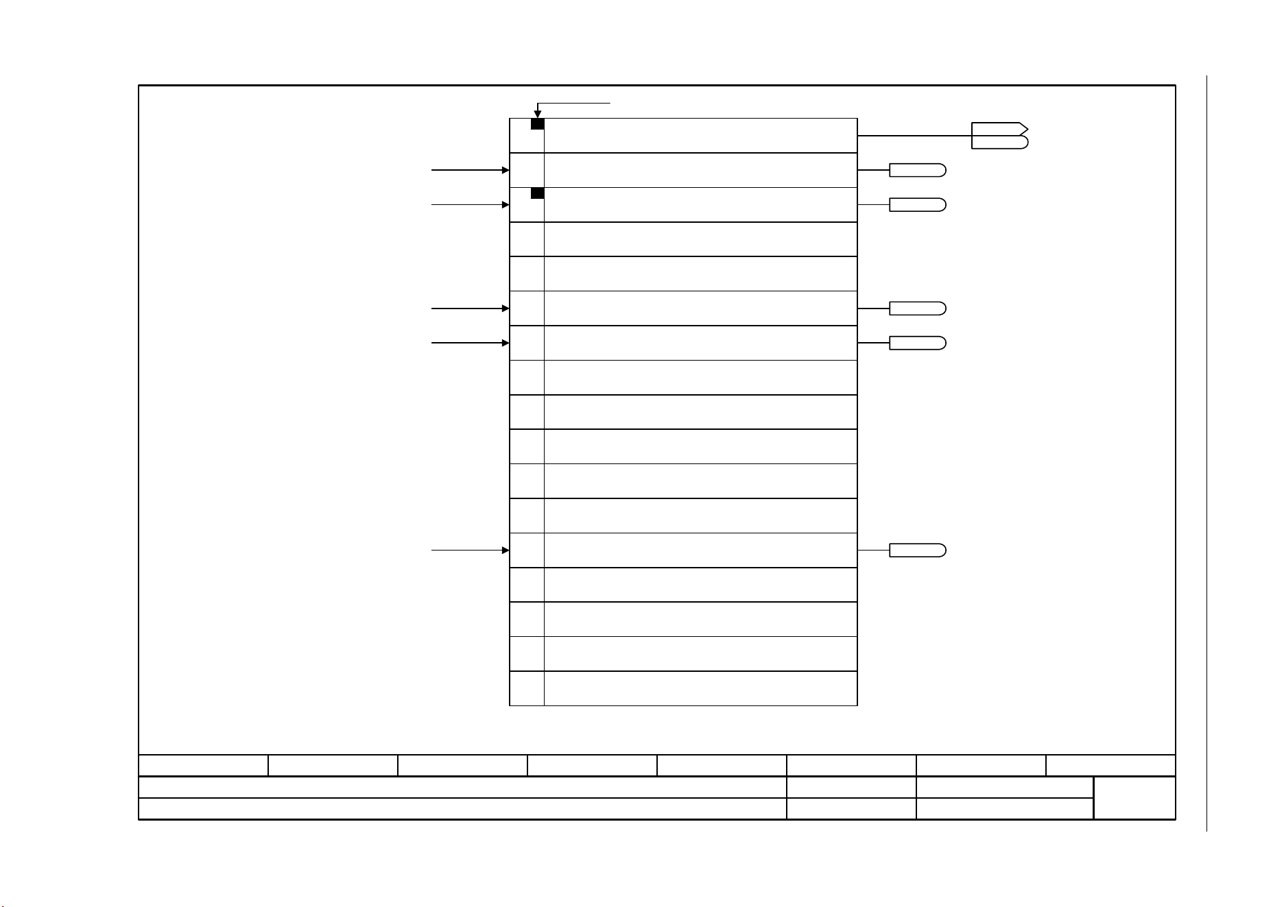
SINAMICS G120C
List Manual (LH13), 04/2014, A5E33840768B AA
379
3 Function diagrams
3.8 Internal control/status words
Fig. 3-51 2537 – Status word, monitoring functions 3
- 2537 -
Function diagram
87654321
fp_2537_97_63.vsd
Internal control/status words
SINAMICS G120C
07.04.2014 V4.7
Status word, monitoring functions 3
11
12
13
14
15
PROFIdrive-Bit
9
10
8
7
6
5
4
3
2
1
0
r2199.11
r2199.5
r2199.1
r2199.0
<1>
[8012.1], [8021.1]
r2199.4
From speed signals
<1> n_act = smoothed speed actual value r2169 [8010.2].
Status word, monitoring functions 3 (r2199)Bit No.
1 = |n_act| < speed threshold value 3 (p2161)
1 = f or n comparison value reached or exceeded (p2141)
1 = Speed setpoint - actual value deviation within tolerance t_on
1 = Ramp-up/ramp-down completed
1 = Torque utilization < torque threshold value 2 (p2194)
ZSW monitor 3
r2199
r2199
Reserved
Reserved
Reserved
Reserved
Reserved
Reserved
Reserved
Reserved
Reserved
Reserved
[8010.8]
From speed signals
[8011.8]
From speed signals
[8011.8]
From speed signals
[8010.8]
From speed signals
[8012.5]
Reserved
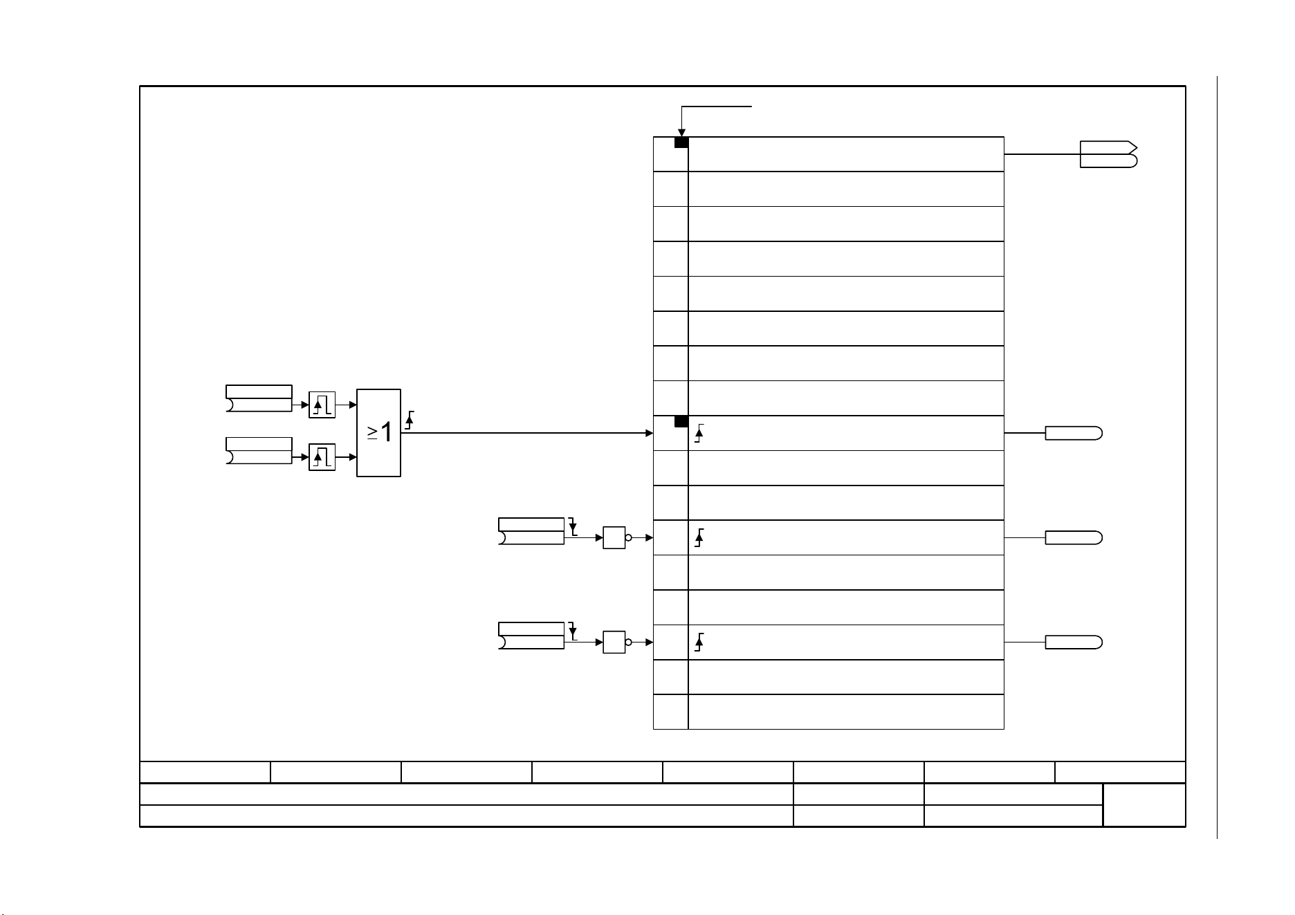
3 Function diagrams
3.8 Internal control/status words
SINAMICS G120C
380 List Manual (LH13), 04/2014, A5E33840768B AA
Fig. 3-52 2546 – Control word, faults/alarms
- 2546 -
Function diagram
87654321
fp_2546_97_05.vsd
Internal control/status words
SINAMICS G120C
07.04.2014 V4.7
Control word, faults/alarms
11
12
13
14
15
PROFIdrive-Bit
9
10
8
7
6
5
4
3
2
1
0
r2138.13
r2138.10
r2138.7
<1>
<1>
<1>
<1>
<1>
These parameters refer to the Command Data Sets (CDS)..
Control word, faults/alarmsBit No.
Reserved
Reserved
Reserved
Reserved
Reserved
Reserved
Reserved
Reserved
Reserved
1 = External alarm 1 (A07850)
1 = Acknowledge fault
Reserved
1 = External fault 1 (F07860)
To alarm buffer [8065.1]
To fault buffer [8060.1]
To fault buffer [8060.1]
STW fault/alarm
r2138
r2138
(722.2)
1. Acknowledge
p2103 [C]
(0)
2. Acknowledge
p2104 [C]
(1)
External alarm 1
p2112 [C]
(1)
External fault 1
p2106 [C]
1
1
Reserved
Reserved
Reserved
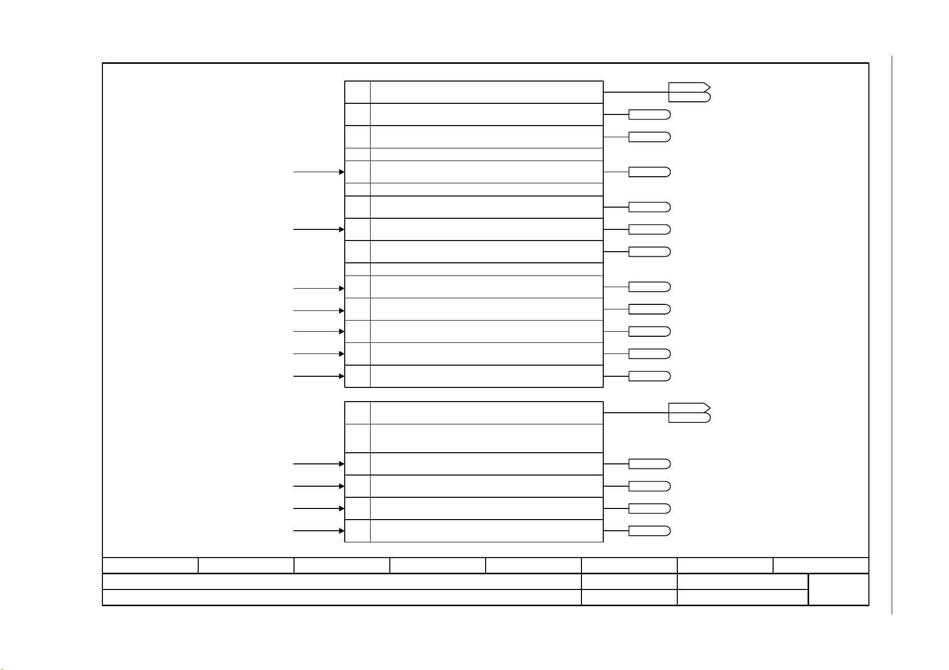
SINAMICS G120C
List Manual (LH13), 04/2014, A5E33840768B AA
381
3 Function diagrams
3.8 Internal control/status words
Fig. 3-53 2548 – Status word, faults/alarms 1 and 2
- 2548 -
Function diagram
87654321
fp_2548_97_61.vsd
Internal control/status words
SINAMICS G120C
07.04.2014 V4.7
Status word, faults/alarms 1 and 2
0
...
11
0
r2139.3
r2139.7
r2135.14
r2135.15
r2135.13
r2135.12
1
r2139.0
r2139.6
r2139.8
...
6
7
8
12
13
14
15
...
3
From the fault buffer [8060.6]
From the alarm buffer [8065.4]
From the thermal monitoring, motor [8016.8]
From the thermal monitoring, power module [8014.8]
From the thermal monitoring, motor [8016.8]
From the thermal monitoring, motor [8016.8]
Status word, faults/alarms 1Bit No.
1 = Acknowledgement running
1 = Fault present
1 = Internal signal 1 present
1 = Alarm present
1 = Internal signal 2 present
1 = Acknowledgement required
Reserved
Reserved
Status word, faults/alarms 2Bit No.
1 = Fault motor overtemperature
1 = Fault, thermal overload, power module
1 = Alarm motor overtemperature
1 = Alarm, thermal overload, power module
ZSW fault/alarm 1
r2139
r2139
ZSW fault/alarm 2
r2135
r2135
Reserved
r2139.1111
1 = Alarm class bit 0
r2139.1212
1 = Maintenance required
13
...
Reserved
r2139.1
1 = Alarm class bit 1
14
15
r2139.13
r2139.14
r2139.15
1 = Maintenance urgently required
1 = Fault gone/can be acknowledged
From the alarm buffer [8065.4]
From the alarm buffer [8065.4]
From the alarm buffer [8065.4]
From the alarm buffer [8065.4]
From the fault buffer [8060.6]
[2510.2]
[2510.2]
[2510.2]
[2510.2]
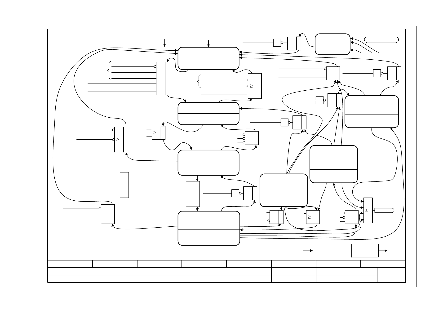
3 Function diagrams
3.8 Internal control/status words
SINAMICS G120C
382 List Manual (LH13), 04/2014, A5E33840768B AA
Fig. 3-54 2610 – Sequence control - Sequencer
- 2610 -
Function diagram
87654321
fp_2610_97_05.vsd
Internal control/status words
SINAMICS G120C
07.04.2014 V4.7
Sequence control - Sequencer
ZSWA.00/01/02 = 1
ZSWA.11 = 1
ZSWA.06 = 0
POWER ON
ZSWA.06 = 1, ZSWA.11 = 0
ZSWA.00/01/02 = 0
ZSWA.00 = 1, ZSWA.11 = 0
<2>
ZSWA.00/01 = 1
ZSWA.11 = 1
ZSWA.02/06 = 0
ZSWA.00/01 = 1
ZSWA.11 = 1
ZSWA.02/06 = 0
ZSWA.00/01 = 1, ZSWA.11 = 0
ZSWA.02/06 = 0
&
(STWA.03)
(STWA.03)
& &
1
[2701.8]
p0857 … p0861
2000.00 µs
[2634]F07300...F07802
F6000
1
<4>
<4>
1
&
(r0046.27 = 0)
&
. . .
1
1
<3>
<4>
<4>
<4>
<4>
<3>
<1>
<4>
<4>
ZSWA.00/01 = 1
ZSWA.11 = 1
ZSWA.02/06 = 0
1
1
&
r0899.8
1
[2503.3]
<6>
<6>
<6>
<4>
1
Jogging
No jogging
"0 = OFF"
Pulse enable HW
De-magnetization completed
Drive at standstill
Enable operation
Enable operation
(STWA.00)
"0 = Coast Stop"
"0 = Quick Stop"
"0 = Coast Stop"
Pulses inhibited
S1: Switching on inhibited
(has priority over jogging)OFF2
OFF3
S2: Ready for switching on
Main contactor is OPEN
Wait for power-up or jog
Wait for "Enable operation"
S3:Ready for operation
S4: Operation
Pulses enabled
Controller enabled
No jog operation: Setpoints enabled
Ramp stop
Bring the drive to n <= 0 along
the ramp-function generator,
then inhibit the pulses
Bring the drive to n <= 0 along
the ramp-function generator,
then inhibit the pulses
S5c: Jogging -
down ramp
Quick Stop
Bring the drive to n <= 0 along
the ramp-function generator,
then inhibit the pulses
Missing enable
signals (r0046)
1 = Controller
enable
Faults
Only if „Safety Integrated“ is active.
The parameters p1226, p1227 and p1228 influence this status.
STWA.xx = control word, sequence control, bit xx (r0898) [2501]; ZSWA.xx = status word, sequence control bit xx (r0899) [2503].
These control commands can also be triggered by a fault response.
The sequence control is implemented according to the PROFIdrive profile.
POWER ON = 24 V electronics supply OFF --> ON or RESET button.<1>
<2>
<3>
<4>
<5>
<6>
<4><3>
<4><3>
<4>
<3>
<4><3>
r0046.8 safety enable
missing
<5>
[2634]
r0046.8 safety enable missing
1
1
1
Pulse enable HW
<4><3>
1
1
[2701.8]
<5>
[2634]
<5>
[2634]
<5>
[2634]
<5>
[2634]
1
r0046.8 safety enable missing
Fault with OFF1- or
OFF3 response
From all states
Jog 1
Jog 2
Jog 1
Jog 2
Jog 1
Jog 2
Jog 1
Jog 2
r0046.8 safety enable missing
r0046.8 safety enable
missing
(STWA.01)
(STWA.02)
(STWA.02)"0 = Quick Stop"
(STWA.01)"0 = Coast Stop"
(STWA.02)"0 = Quick Stop"
(STWA.01)
"0 = Coast Stop"
"0 = Coast Stop"
(STWA.01)
"0 = OFF"
"0 = OFF"
"0 = OFF"
"0 = Quick Stop"
(STWA.02)
"Commissioning completed" (p0010 = 0)
(has priority over jogging)
(STWA.01)
No PM_fault
VDC charged
S5a:
S5b:
Drive at
standstill
1
Drive at standstill
[2701.8]
Pulse enable HW
1
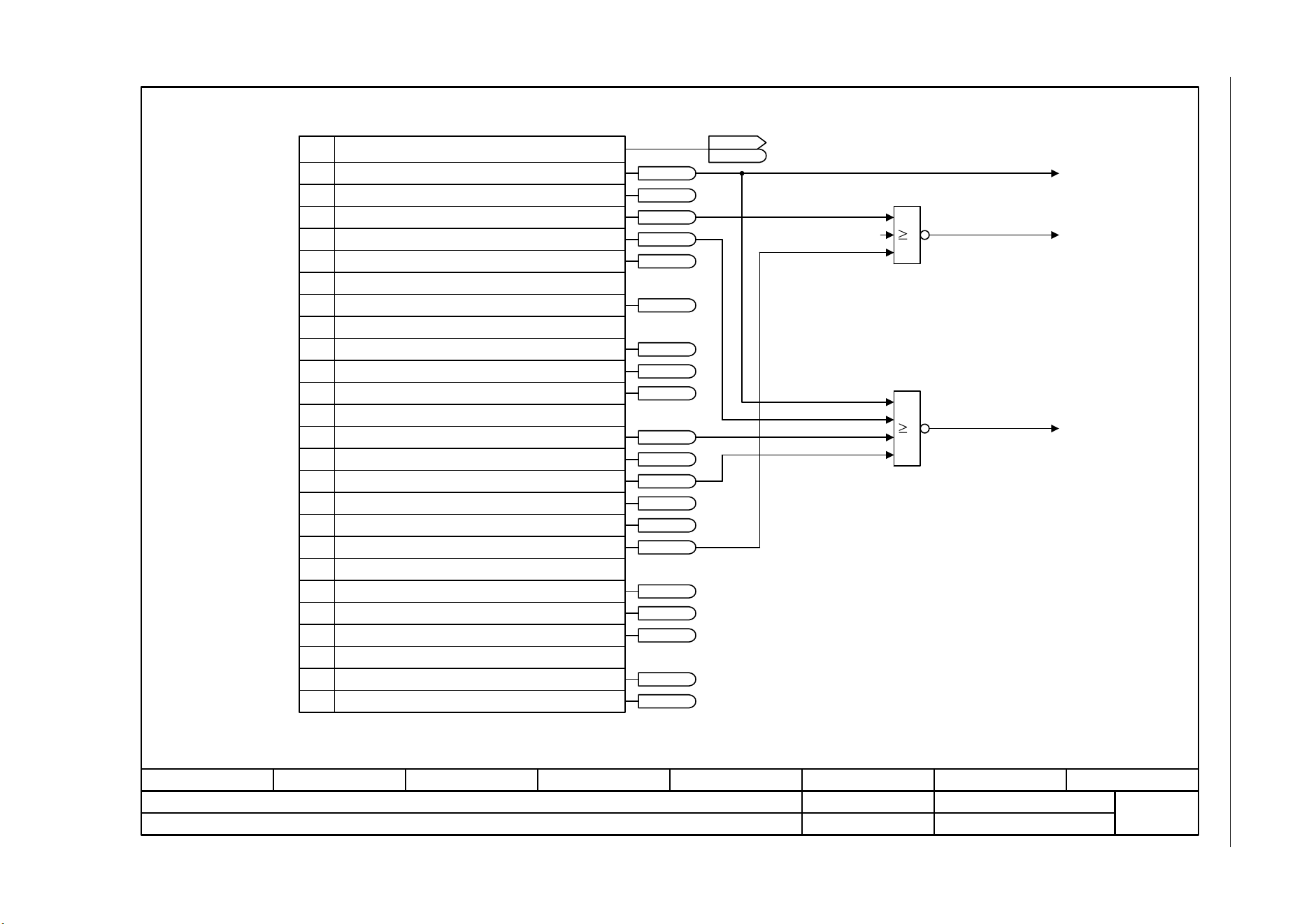
SINAMICS G120C
List Manual (LH13), 04/2014, A5E33840768B AA
383
3 Function diagrams
3.8 Internal control/status words
Fig. 3-55 2634 – Sequence control - Missing enable signals
- 2634 -
Function diagram
87654321
fp_2634_97_05.vsd
Internal control/status words
SINAMICS G120C
07.04.2014 V4.7
Sequence control - Missing enable signals
1
0
2
3
4
...
10
11
12
...
16
17
18
19
20
21
...
...
30
31
r0046.0
r0046.1
r0046.2
r0046.3
r0046.4
r0046.10
r0046.11
r0046.12
r0046.16
r0046.17
r0046.18
r0046.19
r0046.20
r0046.30
r0046.31
1
1
Missing enable signals (r0046)Bit No.
Missing enable sig
r0046
r0046
1 = OFF1 enable missing
1 = OFF2 enable missing
1 = OFF3 enable missing
1 = Operation enable missing
1 = DC current brake, enable missing
1 = Ramp-function generator enable missing
Reserved
1 = Ramp-function generator start missing
1 = Setpoint enable missing
Reserved
1 = OFF1 enable internal missing
1 = OFF2 enable internal missing
1 = OFF3 enable internal missing
1 = Pulse enable internal missing
1 = DC current brake, internal enable missing
1 = PU enable missing
1 = Drive inactive or not operational
1 = Demagnetizing not completed
1 = Brake open missing
1 = Speed controller inhibited
1 = Jog setpoint active
Reserved
Reserved
r0046.21
26
27
28
[3020.5]
0 = Internal quick stop
1 = Internal RFG enable
Fault with OFF3 response
[3070.2]
[3070.4]
[3070.2]
r0046.26
r0046.27
r0046.28
...
Reserved
8
1 = Safety enable missing
r0046.8

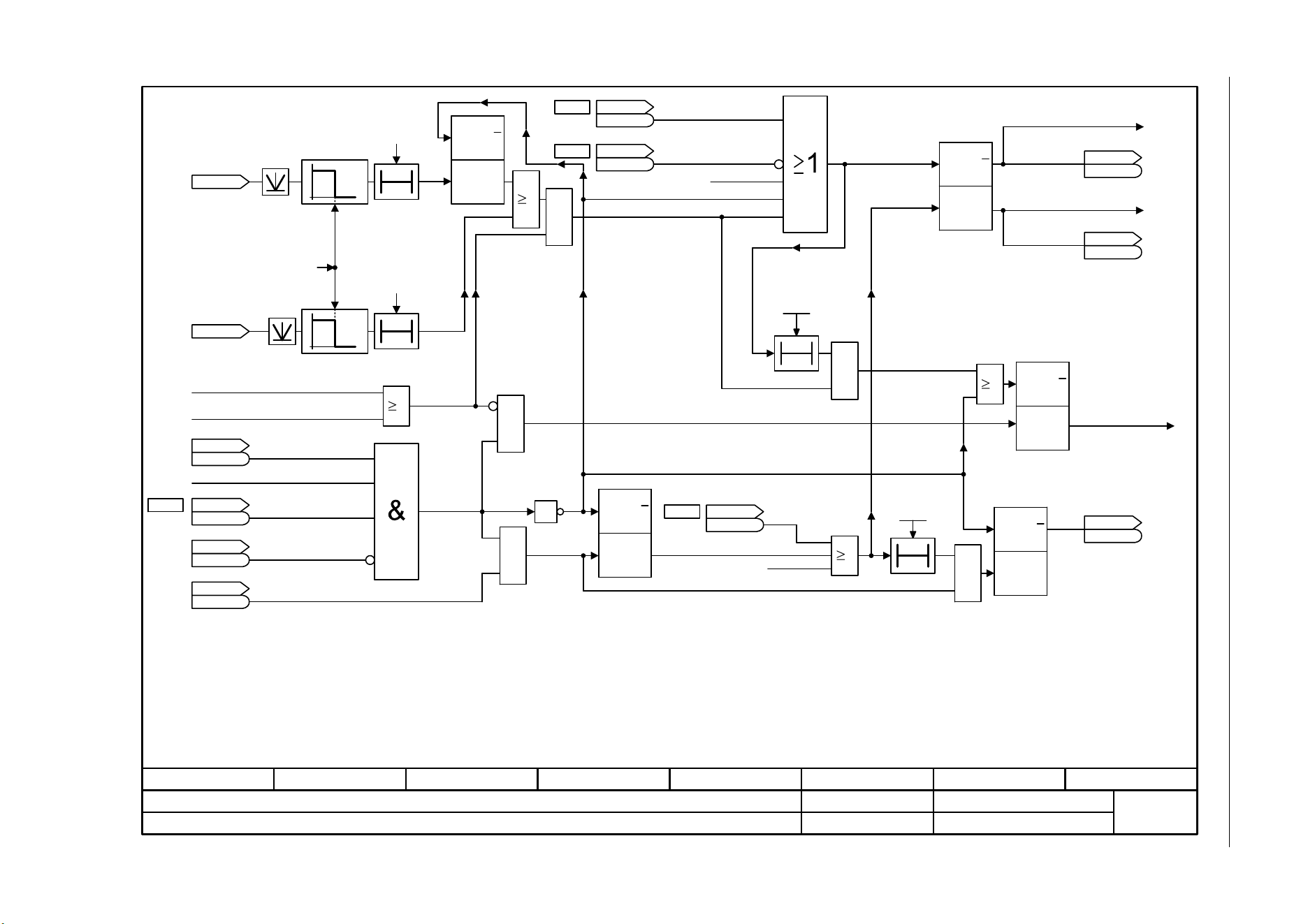
SINAMICS G120C
List Manual (LH13), 04/2014, A5E33840768B AA
385
3 Function diagrams
3.9 Brake control
Fig. 3-56 2701 – Basic brake control
- 2701 -
Function diagram
87654321
fp_2701_97_05.vsd
Brake Control
SINAMICS G120C
07.04.2014 V4.7
Basic brake control
1
T0
T0
p1215 = 2
1
0
1
0
T0
1
1
1
<3>
<1>
<4>
<3>
T0
[2814.2]
[2503.3]
[2503.3]
&
<5>
<4>
<2>
<1>
<1>
[2501.3]
p0855
<5>
<6>
[2503.3]
<2>
<6>
<9>
<7>
[2501.3]
p0858
[2501.3]
p0852
[2503.7]
[2503.7]
<7>
Q
Q
RESET
(Q=0)
SET
(Q=1)
Q
Q
RESET
(Q=0)
SET
(Q=1)
Q
Q
RESET
(Q=0)
SET
(Q=1)
Q
Q
RESET
(Q=0)
SET
(Q=1)
Q
Q
RESET
(Q=0)
SET
(Q=1)
<2>
p1215 = 0
&
&
&
1
&
<8>
ZSW seq_ctrl
r0899
r0899
.4
r0063
n_act [rpm]
[0]
OFF 1 present
OFF 3 present
1 = No coast down active
Pulse enable
1 = Operation enabled
1 = Switching on
inhibited active
1 = Magnetizing completed
STW seq_ctrl
r0898
r0898
.3
ZSW seq_ctrl
r0899
r0899
.6
Missing enable sig
r0046
r0046
.21
unsmoothed
Brake t_close
0 ... 10000 [ms]
p1217 (100)
1 = Enable speed
controller
STW seq_ctrl
r0898
r0898
.12
1 = Unconditionally
close the holding brake
STW seq_ctrl
r0898
r0898
.14
Brake t_open
0 ... 10000 [ms]
p1216 (100)
1 = Unconditionally
open the holding
brake
STW seq_ctrl
r0898
r0898
.7
1 = Command, close holding brake
PU enable internal missing
Pulse enable HW
1 = Holding brake open
ZSW seq_ctrl
r0899
r0899
.12
ZSW seq_ctrl
r0899
r0899
.13
1 = Open the holding brake
Close "normal" brake
Close brake
Open brake
<8>
Priority assignment (high -> low): p1215, p0858, p0855, p0856, sequence control.
If p1215 = 0, 2 -> t = 0 ms.
Only if Safety Integrated is active.
Monitoring time is initialized in dependence on the rated power of Power Module.
If an external motor holding brake is used, p1215 should be set to 3 and r0899.12 should be interconnected as control signal.
r0046.21 = 0, as long as r0046.0 = 1 (OFF1 enable missing or switching on inhibited).
r0046.21 = 1, if p0858 = 1 or p0856 = 0.
The signal generation is shown simplified.
The internal signal includes signals that lead to OFF1 or OFF3 (e. g. BICO or fault response).
If the brake is permanently applied or released (p0855, p0858 or p1215), the drive does not wait while the brake is released or applied.
ZSW cl-loop ctrl
r0056
r0056
.4
[2526.6]
[6030.2]
Start frequency with U/f control: p1351, p1352 [6310.6]; Start torque with vector control: p1475 [6040.3]
<9>
r0060
n_set before filt.
[rpm]
[4715.7]
0.010 [s]
20.00 [1/min]
300 [s]
p0856
[6730.6], [6731.6]

3 Function diagrams
3.10 Safety Integrated Basic Functions
SINAMICS G120C
386 List Manual (LH13), 04/2014, A5E33840768B AA
3.10 Safety Integrated Basic Functions
Function diagrams
2800 – Parameter manager 387
2802 – Monitoring functions and faults/alarms 388
2804 – Status words 389
2810 – STO: Safe Torque Off 390
2812 – F-DI: Fail-safe Digital Input 391
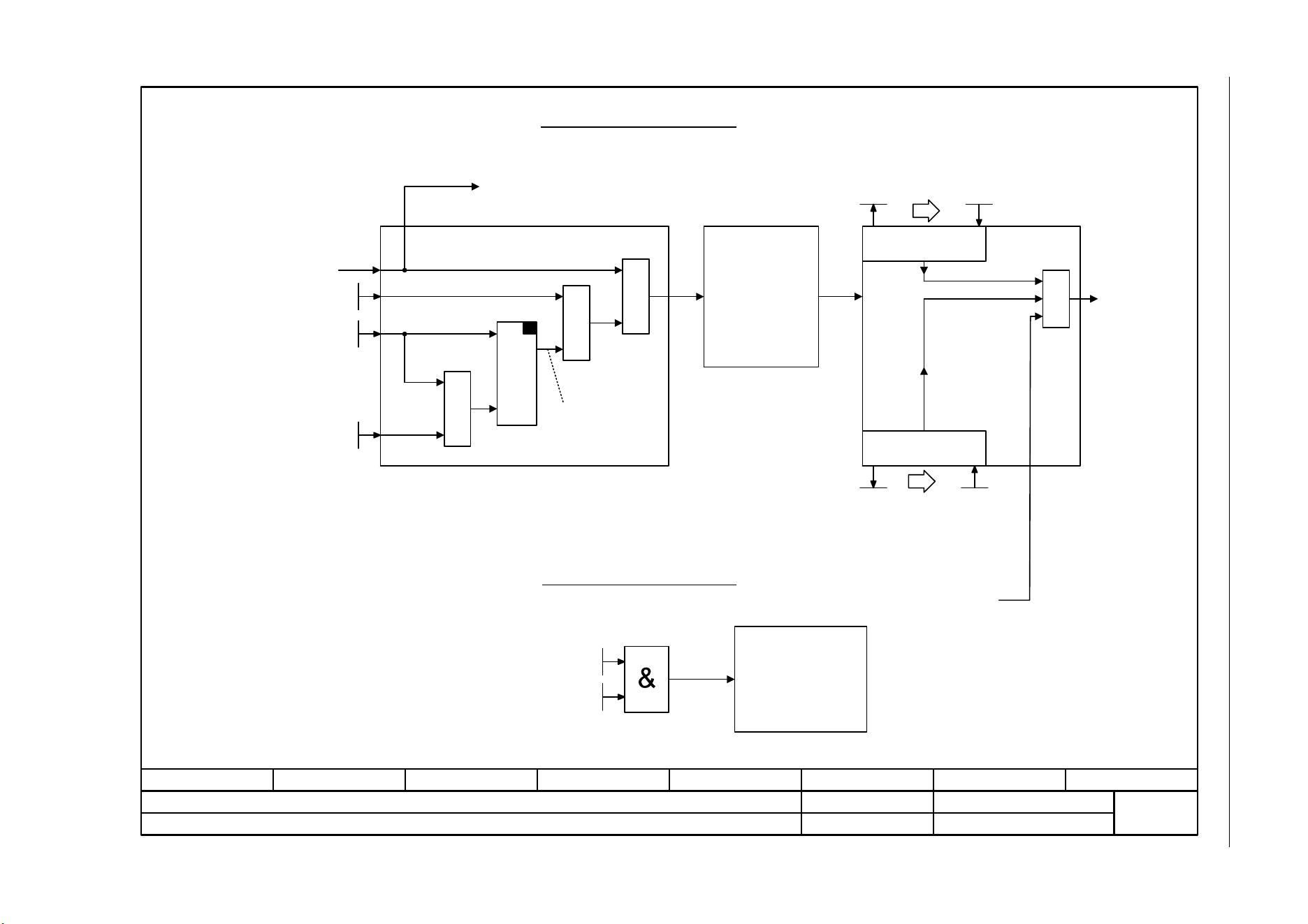
SINAMICS G120C
List Manual (LH13), 04/2014, A5E33840768B AA
387
3 Function diagrams
3.10 Safety Integrated Basic Functions
Fig. 3-57 2800 – Parameter manager
- 2800 -
Function diagram
87654321
fp_2800_97_05.vsd
Safety Integrated Basic Functions
SINAMICS G120C
07.04.2014 V4.7
Parameter manager
x
y
=
=
SET
y = x
=
=
&
&
SI act chksm P1
r9798
Changing safety parameters
Resetting safety parameters
Safety parameterizing
enable
Checksum check
for safety
parameters
Safety parameters can
be reset to the factory
settings via p0970,
p3900.
Safety parameters
can be changed.
Safety-IBN-Modus
[2802.1][2810.4]
--> STO anwählen
Effective password
Enter password
Safety Integrated commissioning
p0010 = 95
Safety parameters
are valid.
p0010 unequal 95
Exit safety
commissioning
mode
Inhibit safety functions
SI password inp
p9761
SI setp_chksm P1
p9799
SI act_chksm P2
r9898
SI setp_chksm P2
p9899
SI enable fct P2
p9801 = 0
[2810.3]
SI password new
p9762
SI ackn password
p9763
SI enable fct P1
p9601 = 0
[2810.3]
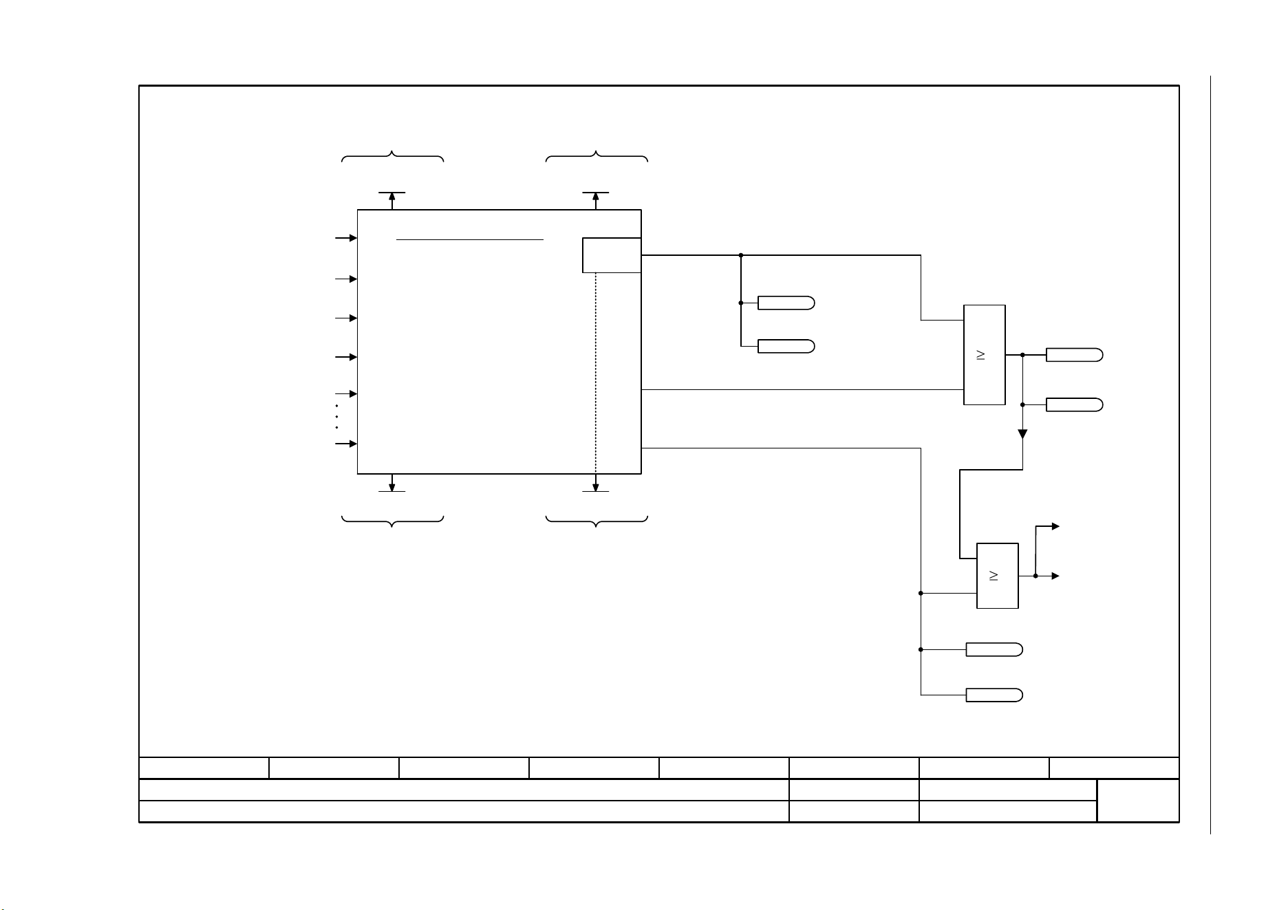
3 Function diagrams
3.10 Safety Integrated Basic Functions
SINAMICS G120C
388 List Manual (LH13), 04/2014, A5E33840768B AA
Fig. 3-58 2802 – Monitoring functions and faults/alarms
- 2802 -
Function diagram
87654321
fp_2802_97_69.vsd
Safety Integrated Basic Functions
SINAMICS G120C
07.04.2014 V4.7
Monitoring functions and faults/alarms
[2810.6] DIAG_U
[2810.6] DIAG_L
F01611
F30611
[2810.3]
F01600/F30600
1
1
SI version Drv P1
r9770
Safety monitoring functions
Faults/alarms
Cross checking list
[2810.1] STO-Klemme P1 (r0722.4)
[2810.1] STO terminal P2 (r0722.5)
[2800.3] Safety commissioning mode
Additional diagnostics
Information
1 = Faults with response "NONE"
1 = Faults with response "immediate pulse suppression"
1 = Faults with response "immediate pulse suppression"
that cannot be acknowledged
1 = STOP A
To Safe Torque Off
"STOP A initiated"
Diagnostics for STOP F
SI mon_clk cyc P1 [ms]
r9780
Monitoring clock cycleSafety Integrated version
SI CDC_list P1
r9794
SI diag STOP F P1
r9795
P1: F/A01600 ... 01699
P2: F/A30600 ... 30699
STOP F
[2804.1]
[2804.4]
[2804.2]
[2804.5]
[2804.2]
[2804.5]
r9772.15
1 = STOP F active
r9872.15
1 = STOP F active
1 = STOP A active
r9772.10
r9872.10
1 = STOP A active
r9772.9
1 = STOP A cannot be acknowledged, active
r9872.9
1 = STOP A cannot be acknowledged, active
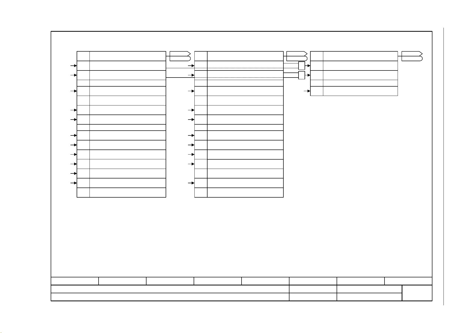
SINAMICS G120C
List Manual (LH13), 04/2014, A5E33840768B AA
389
3 Function diagrams
3.10 Safety Integrated Basic Functions
Fig. 3-59 2804 – Status words
- 2804 -
Function diagram
87654321
fp_2804_97_05.vsd
Safety Integrated Basic Functions
SINAMICS G120C
07.04.2014 V4.7
Status words
1
9
10
...
15
0[2810.4]
[2810.7]
[2802.5]
[2802.8]
1
0
31
[2810.5]
[2802.7]
... ...
SI status P1
r9772
r9772
Status word Safety Integrated
Processor 1
Bit No.
1 = STO selected on Processor 1
1 = STO active on Processor 1
Reserved
1 = STOP A cannot be acknowledged, active
1 = STOP A active
Reserved
1 = STOP F active
Bit No.
Reserved
Status word Safety Integrated
Processor 1 and Processor 2
1 = STO selected in drive
1 = STO active in drive
1 = The shutdown paths must be tested
17
18
16
19
20
1 = STO cause: Safety commissioning mode
1 = STO cause: selection via terminal
1 = STO cause: selection via motion
monitoring functions
1 = STO cause: actual value missing
1 = STO cause: selection PROFIsafe
SI status P1+P2
r9773
r9773
1
0 &
&
SI Status P2
r9872
r9872
Bit No.
Status word Safety Integrated Processor2
1 = STO selected on Processor 2
1 = STO active on Processor 2
Status (Processor 1 + Processor 2)Status (Processor 2)Status (Processor 1)
...
Reserved
9
1 = STOP A cannot be acknowledged, active
10
1 = STOP A active
...
Reserved
15
1 = STOP F active
16
1 = STO cause: Safety commissioning mode
17
1 = STO cause: selection via terminal
18
1 = STO cause: selection via motion
monitoring functions
19
Reserved
20
1 = STO cause: selection PROFIsafe
[2800.3]
[2810.2]
[2802.7]
[2802.8]
[2802.5]
[2800.3]
[2810.2]
[2810.4]
[2810.6]
[2810.2]
[2810.2]
[2810.2]
[2819.8]
[2810.2]
7
8
1 = STO terminal state on Processor 1
Reserved
7
8
1 = STO terminal state on Processor 2
Reserved
[2810.2] [2810.2]
21
1 = STO cause selection on processor 2
21
1 = STO cause selection on processor 1
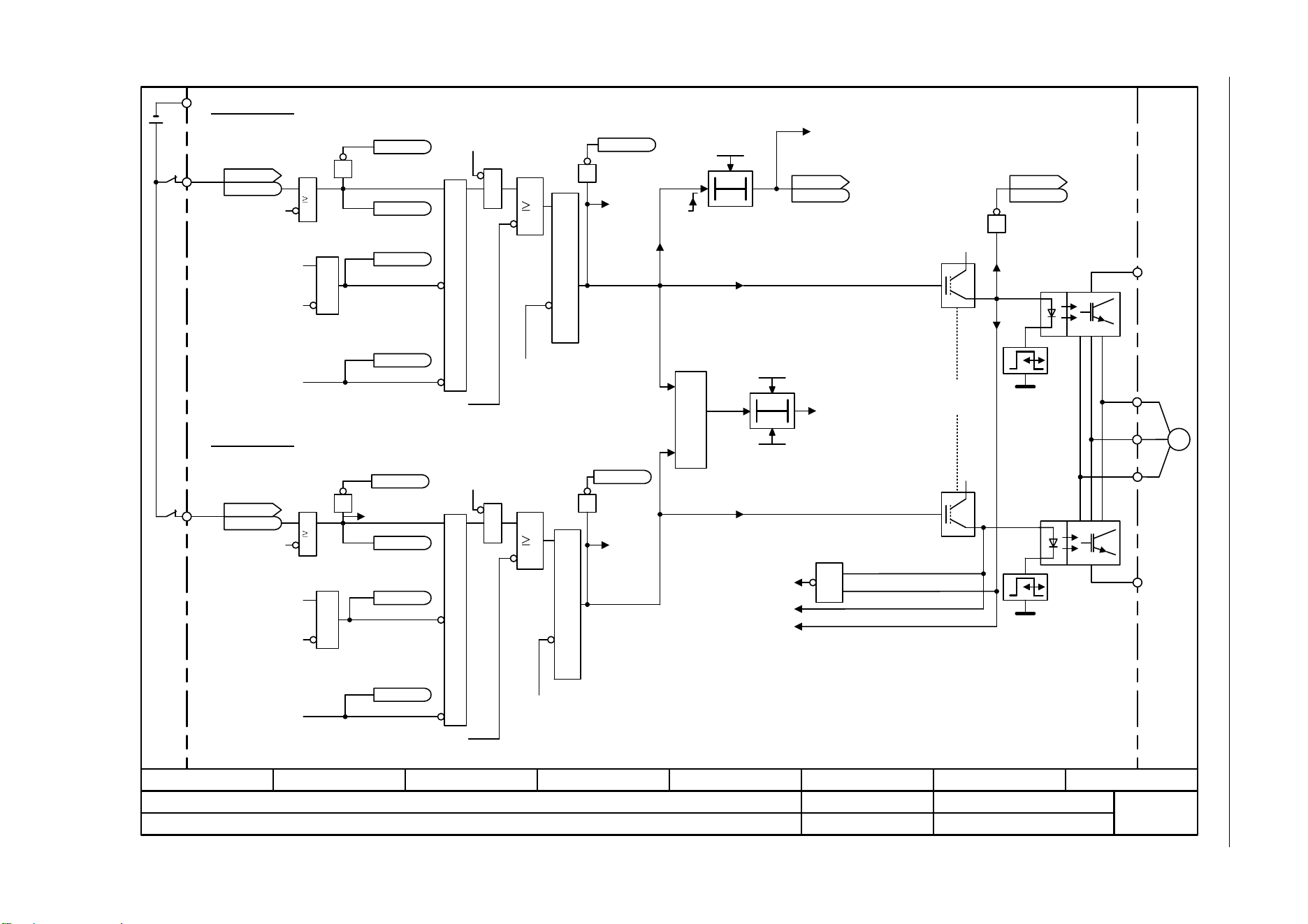
3 Function diagrams
3.10 Safety Integrated Basic Functions
SINAMICS G120C
390 List Manual (LH13), 04/2014, A5E33840768B AA
Fig. 3-60 2810 – STO: Safe Torque Off
- 2810 -
Function diagram
87654321
fp_2810_97_05.vsd
Safety Integrated Basic Functions
SINAMICS G120C
07.04.2014 V4.7
STO (Safe Torque Off)
T0
F01611 (P1)
F30611 (P2)
M
~
U
V
W
&
+5 V
<1>
[2802.1] DIAG_L
[2802.1] DIAG_U
<3>
<3>
=1
T0
<1>
<2>
<3>
SI FCP Timer
0.00 ... 9000.00 [h]
p9659 (8.00)
SI F-DI chg t P1
0.00 ... 2000.00 [ms]
p9650 (500.00)
Timer for forced
checking
procedure
A01699
"Shutdown
paths must
be tested"
Upper IGBT
bridge halve
Safe pulse
suppression
Gating unit
Lower IGBT
bridge halve
Gating unit
Shutdown
path from P2
0 = STO_P2
Monitoring for simultaneous occurrence
0 = Request pulse suppression P2
Switch-on delay starts when the "request pulse suppression P1" is withdrawn.
Redundant functions in the Processor 1 (P1) and Processor 2 (P2).
Transistors inhibited for a "0" signal.
STO: Safe Torque Off
1 = "STO active" for
sequence control
Shutdown path
from P1
0 = STO_P1
0 = Request Pulse suppression P1
SI F-DI chg t P2
0.00 ... 2000000.00 [µs]
p9850 (500000.00)
1 = STO active on Control Unit
SI status P1
r9772
r9772
.1
[2804.2]
1 = Shutdown
paths must
be tested
SI status P1+P2
r9773
r9773
.31
+24 V
1
1 = STOP A [2802.8]
&
1
<2>
Kl. 17
[2802.2]
[2804.2]
&
1 = Safety commissioning mode
CU DI status
r0722
r0722
.4
CU DI status
r0722
r0722
.5
Kl. 16
Processor 2
PROFIsafe enabled for
dbSI0 (p9601.2 = 0 and
p9601.3 = 1) (P1)
[2804.1]
&
0 = Select PROFIsafe
via STO
1 = STO cause:
selection PROFIsafe
[2804.1]
1 = STO cause: selection via
motion monitoring functions
[2804.2]
STO initiate
SI enable, functions integrated in the drive (p9601 0)
1
1 = STOP A [2802.8]
&
1
&
1 = Safety commissioning mode
&
1 = STO cause:
selection PROFIsafe
[2804.4]
1 = STO cause: selection via
motion monitoring functions
[2804.2]
PROFIsafe enabled for
dbSI0 (p9801.2 = 0 and
p9801.3 = 1) (P2)
0 = Select PROFIsafe
via STO
STO initiate
SI enable, functions integrated in the drive (p9801 0)
1 = STO selected on
P2
[2802.2]
[2804.4]
1
Enable STO via
terminals (P1)
1
1
Enable STO via
terminals (P2)
1
[2804.4]
[2825.8]
[2825.8]
[2800.3]
[2800.3]
1
1 = STO
selected on P1
Processor 1
&
&
1 = STO cause:
selection via terminal
[2802.2]
1 = STO cause:
selection via terminal
+5 V
r9772.0
r9772.20
r9772.17
r9772.18
r9772.7
r9872.17
r9872.0
r9872.20
r9872.18
r9872.7
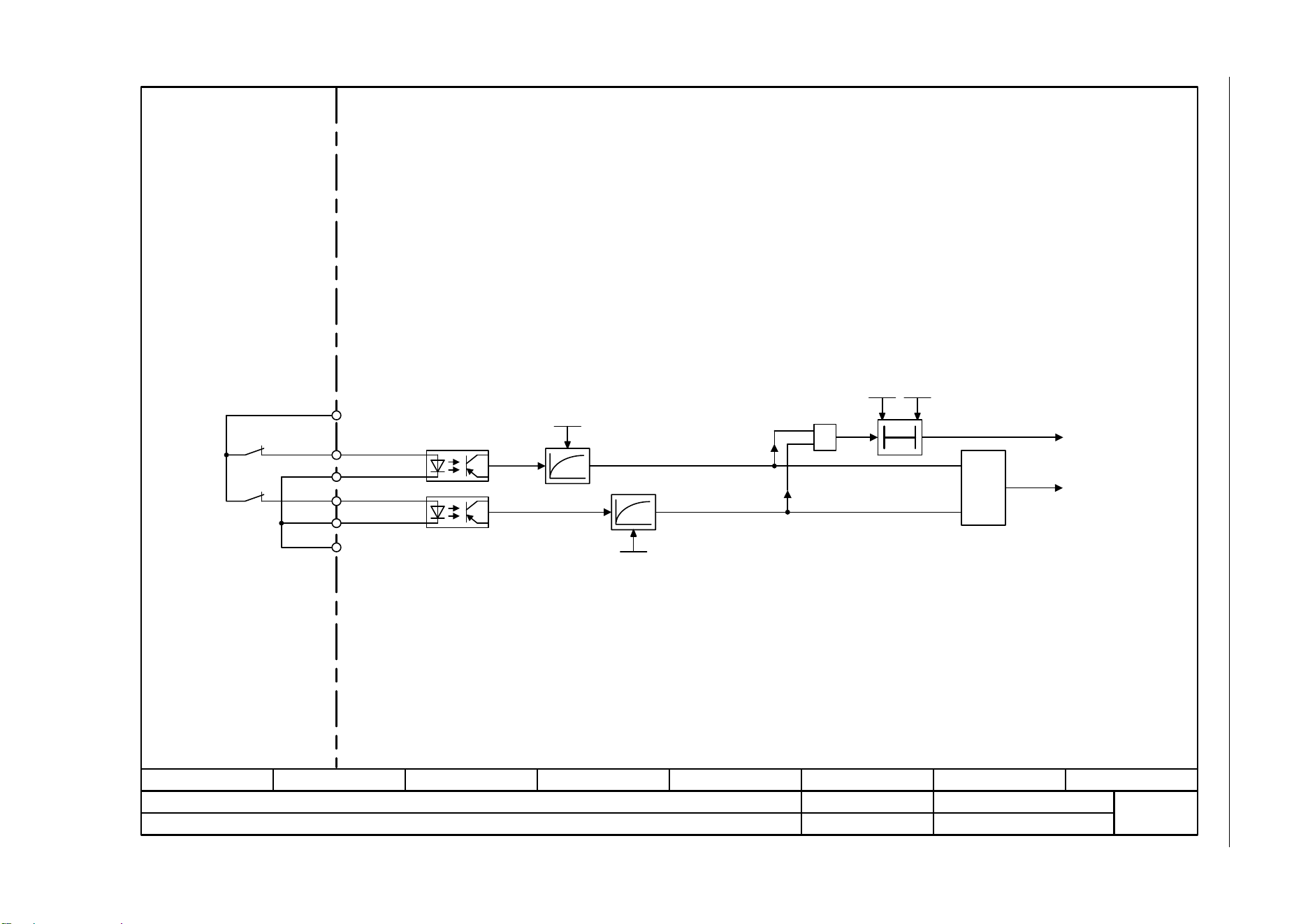
SINAMICS G120C
List Manual (LH13), 04/2014, A5E33840768B AA
391
3 Function diagrams
3.10 Safety Integrated Basic Functions
Fig. 3-61 2812 – F-DI: Fail-safe Digital Input
- 2812 -
Function diagram
87654321
fp_2812_97_66.vsd
Safety Integrated Basic Functions
SINAMICS G120C
07.04.2014 V4.7
F-DI (Fail-safe Digital Input)
&
F-DI 0
=1
SI STO t_debou P1
0.00 ... 100.00 [ms]
p9651 (1.00)
SI STO t_debou P2
0.00 ... 100000.00 [µs]
p9851 (0.00)
T0
SI F-DI chg t P1
0.00 ... 2000.00 [ms]
p9650 (500.00)
SI F-DI chg t P2
0.00 ... 2000000.00 [µs]
p9850 (500000.00)
Kl. 9
Kl. 16
Kl. 69
Kl. 17
Kl. 34
Kl. 28
GND
+24V OUT
DI 4
DI COM
DI 5
DI COM2
[2810.6]

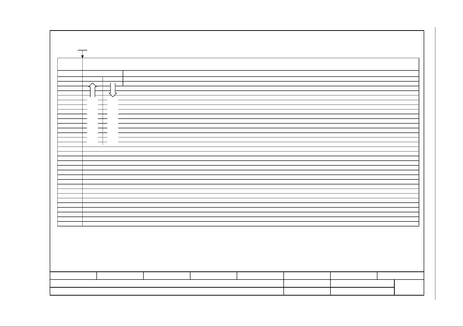
SINAMICS G120C
List Manual (LH13), 04/2014, A5E33840768B AA
393
3 Function diagrams
3.11 Safety Integrated PROFIsafe
Fig. 3-62 2915 – Standard telegrams
- 2915 -
Function diagram
87654321
fp_2915_97_63.vsd
Safety Integrated PROFIsafe
G120C DP/ PN
07.04.2014 V4.7
Standard telegrams
PZD6
PZD8
PZD9
PZD10
PZD11
PZD13
PZD14
PZD15
PZD16
PZD12
PZD7
PZD5
PZD4
PZD1
PZD2
PZD3
PZD17
PZD18
PZD19
PZD24
PZD26
PZD27
PZD28
PZD29
PZD31
PZD32
PZD30
PZD25
PZD23
PZD22
PZD20
PZD21
30
S_STW1 S_ZSW1
Interconnec-
tion is made
according to
Ps telegram_sel
p60022
Telegram
Receive telegram from
PROFIBUS/PROFINET
Send telegram to
PROFIBUS/PROFINET

3 Function diagrams
3.12 Setpoint channel
SINAMICS G120C
394 List Manual (LH13), 04/2014, A5E33840768B AA
3.12 Setpoint channel
Function diagrams
3001 – Overview 395
3010 – Fixed speed setpoints, binary selection (p1016 = 2) 396
3011 – Fixed speed setpoints, direct selection (p1016 = 1) 397
3020 – Motorized potentiometer 398
3030 – Main/supplementary setpoint, setpoint scaling, jogging 399
3040 – Direction limitation and direction reversal 400
3050 – Skip frequency bands and speed limitations 401
3070 – Extended ramp-function generator 402
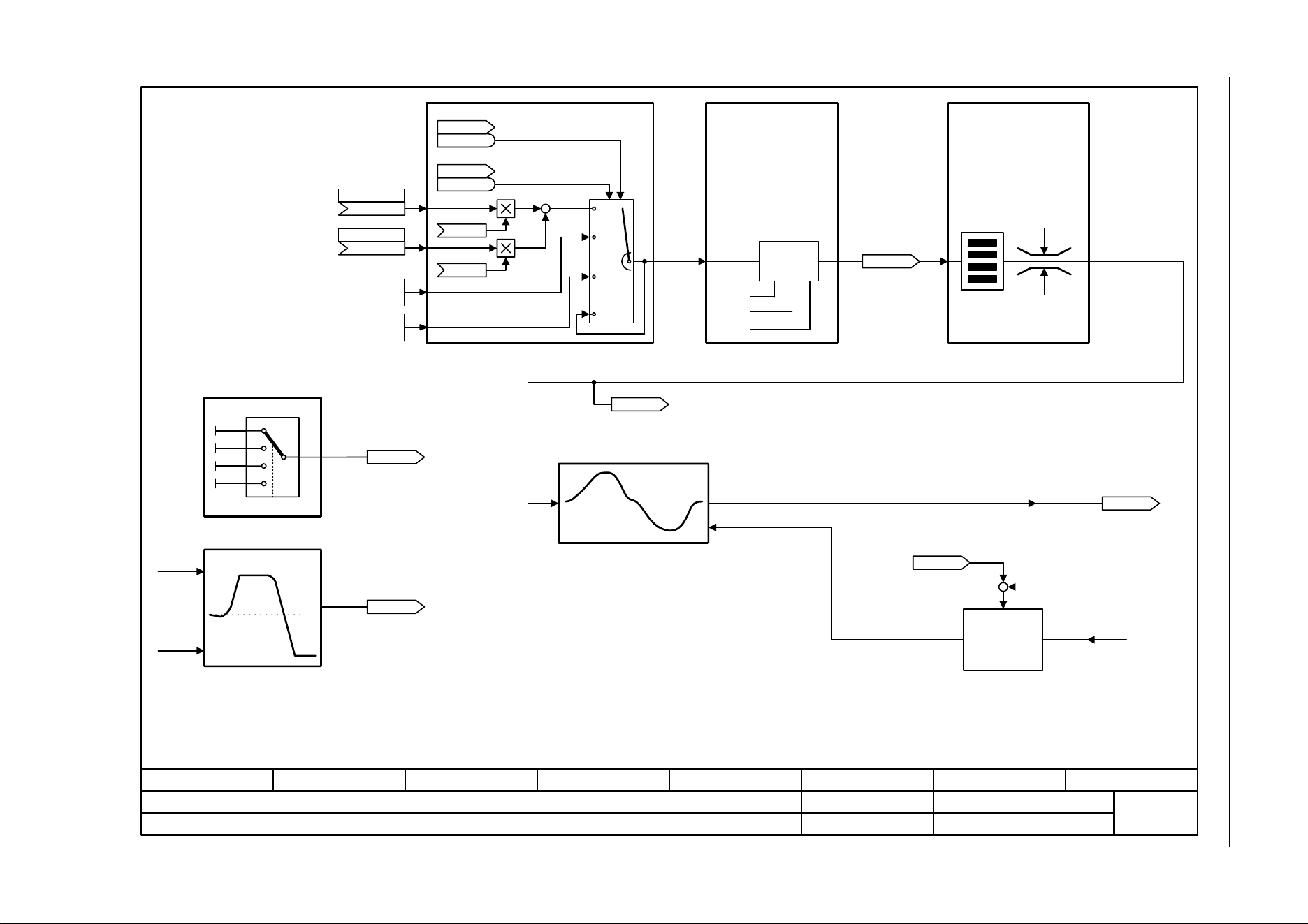
SINAMICS G120C
List Manual (LH13), 04/2014, A5E33840768B AA
395
3 Function diagrams
3.12 Setpoint channel
Fig. 3-63 3001 – Overview
- 3001 -
Function diagram
87654321
fp_3001_97_05.vsd
Setpoint channel
SINAMICS G120C
07.04.2014 V4.7
Overview
+
+
+ / -
+
–
p1076
p1071
pos
neg
(-1)
[6020.1]
0 0
0 1
1 0
1 1
Main setpoint
(755[0])
p1070 [C]
Suppl setp
(0)
p1075 [C]
r1024
n_set_fixed eff [rpm]
Jog 1 n_set
-210000.000 ... 210000.000 [rpm]
p1058 [D] (150.000)
Jog 2 n_set
-210000.000 ... 210000.000 [rpm]
p1059 [D] (-150.000)
raise
Main/supplementary setpoint, setpoint
scaling, jogging
r1050
Mop setp after RFG [rpm]
Motorized potentiometer
Fixed speed setpoints, binary
selection (p1016 = 2)
Extended ramp-function generator
n_set_1
Simulate ramp-function
generator
Direction limitation and
direction reversal
Skip (suppression)
bandwidth and speed limiting
Ramp-function
generator
tracking
RFG setpoint
at the input
STW seq_ctrl
r0898
r0898
.8
STW seq_ctrl
r0898
r0898
.9
n_act
M_limit
r1438
n_ctrl n_set [rpm]
lower
r1119
RFG setp at inp [rpm]
[3030] [3050]
[3070]
[3020]
r1114
Setp after limit
[rpm]
r1170
n_ctrl setp sum
[rpm]
[3040]
[3010]
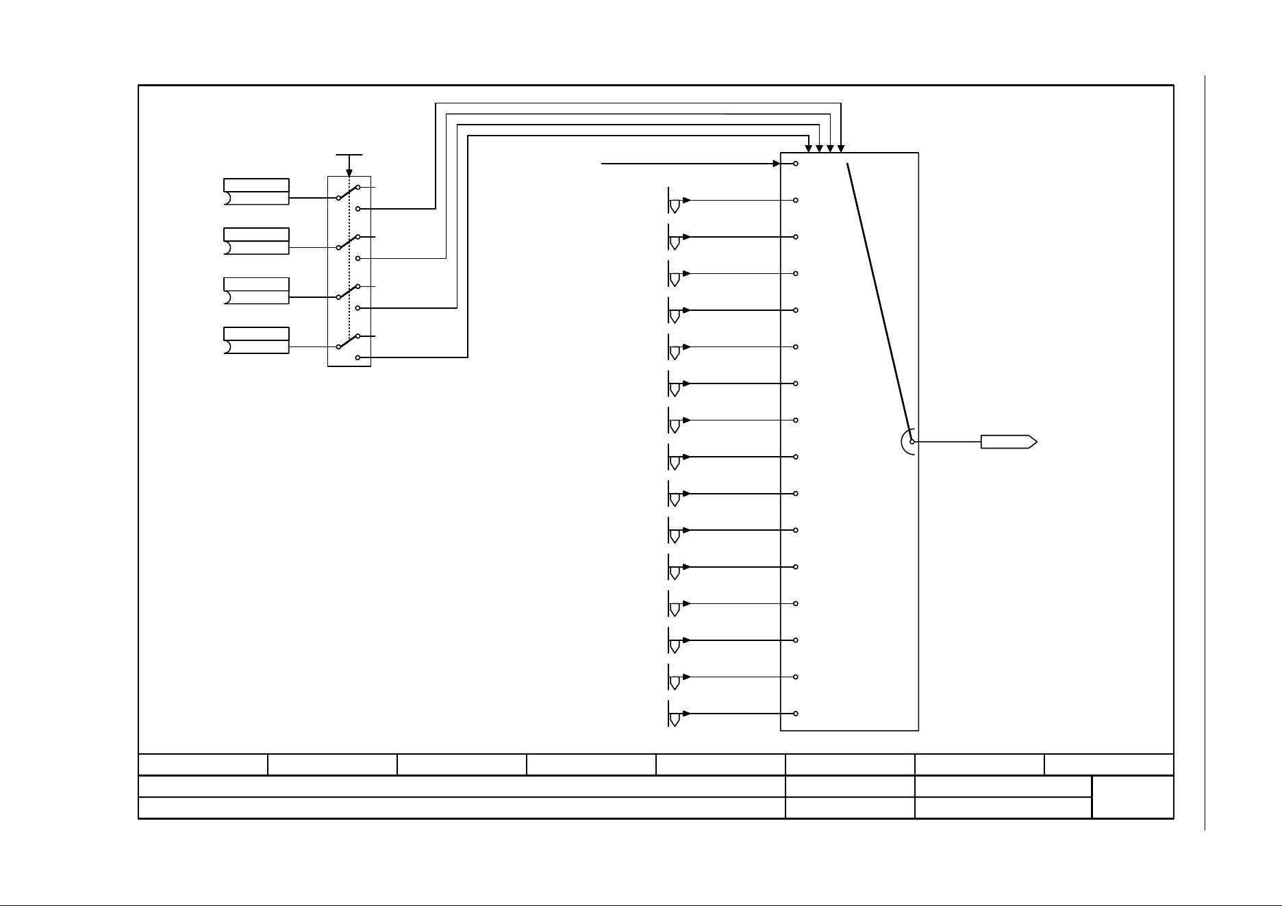
3 Function diagrams
3.12 Setpoint channel
SINAMICS G120C
396 List Manual (LH13), 04/2014, A5E33840768B AA
Fig. 3-64 3010 – Fixed speed setpoints, binary selection (p1016 = 2)
- 3010 -
Function diagram
87654321
fp_3010_97_05.vsd
Setpoint channel
SINAMICS G120C
07.04.2014 V4.7
Fixed speed setpoints, binary selection (p1016 = 2)
0 0 1 1
0 1 0 1
0 1 1 0
0 1 1 1
1 0 0 1
1 0 1 0
1 0 1 1
1 1 0 0
1 1 0 1
1 1 1 0
1 1 1 1
0 0 0 1
0 0 1 0
0.000 0 0 0 0
0 1 0 0
1 0 0 0
r1024
n_set_fixed eff [rpm]
(0)
n_set_fixed Bit 0
p1020 [C]
(0)
n_set_fixed Bit 1
p1021 [C]
(0)
n_set_fixed Bit 2
p1022 [C]
(0)
n_set_fixed Bit 3
p1023 [C]
n_set_fix select
1 ... 2
p1016 (1)
[3011]
1
1
1
1
2
2
2
2
[3011]
[3011]
n_set_fixed 1 [rpm]
p1001 [D] (0.000)
n_set_fixed 2 [rpm]
p1002 [D] (0.000)
n_set_fixed 3 [rpm]
p1003 [D] (0.000)
n_set_fixed 4 [rpm]
p1004 [D] (0.000)
n_set_fixed 5 [rpm]
p1005 [D] (0.000)
n_set_fixed 6 [rpm]
p1006 [D] (0.000)
n_set_fixed 7 [rpm]
p1007 [D] (0.000)
n_set_fixed 8 [rpm]
p1008 [D] (0.000)
n_set_fixed 9 [rpm]
p1009 [D] (0.000)
n_set_fixed 10 [rpm]
p1010 [D] (0.000)
n_set_fixed 11 [rpm]
p1011 [D] (0.000)
n_set_fixed 12 [rpm]
p1012 [D] (0.000)
n_set_fixed 13 [rpm]
p1013 [D] (0.000)
n_set_fixed 14 [rpm]
p1014 [D] (0.000)
n_set_fixed 15 [rpm]
p1015 [D] (0.000)
[3011]
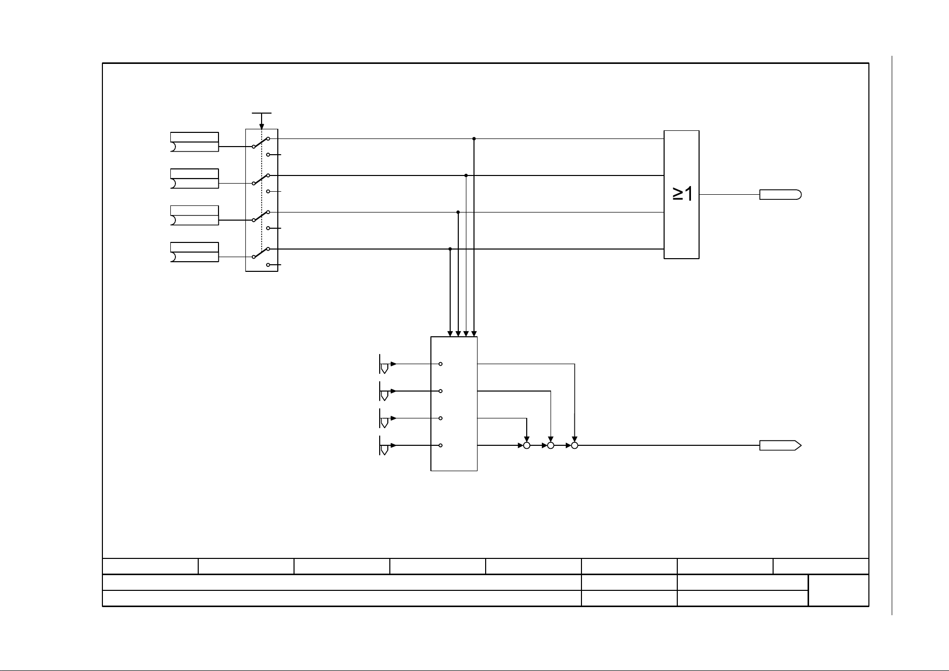
SINAMICS G120C
List Manual (LH13), 04/2014, A5E33840768B AA
397
3 Function diagrams
3.12 Setpoint channel
Fig. 3-65 3011 – Fixed speed setpoints, direct selection (p1016 = 1)
- 3011 -
Function diagram
87654321
fp_3011_97_05.vsd
Setpoint channel
SINAMICS G120C
07.04.2014 V4.7
Fixed speed setpoints, direct selection (p1016 = 1)
0 0 0 1
0 0 1 0
1 0 0 0
0 1 0 0
r1024
n_set_fixed eff [rpm]
n_setp_fix status
r1025
(0)
n_set_fixed Bit 0
p1020 [C]
(0)
n_set_fixed Bit 1
p1021 [C]
(0)
n_set_fixed Bit 2
p1022 [C]
(0)
n_set_fixed Bit 3
p1023 [C]
1
2
2
2
2
n_set_fix select
1 ... 2
p1016 (1)
1
1
1
[3010]
[3010]
[3010]
[3010]
n_set_fixed 1 [rpm]
p1001 [D] (0.000)
n_set_fixed 2 [rpm]
p1002 [D] (0.000)
n_set_fixed 3 [rpm]
p1003 [D] (0.000)
n_set_fixed 4 [rpm]
p1004 [D] (0.000)
++
++
+
+
.0
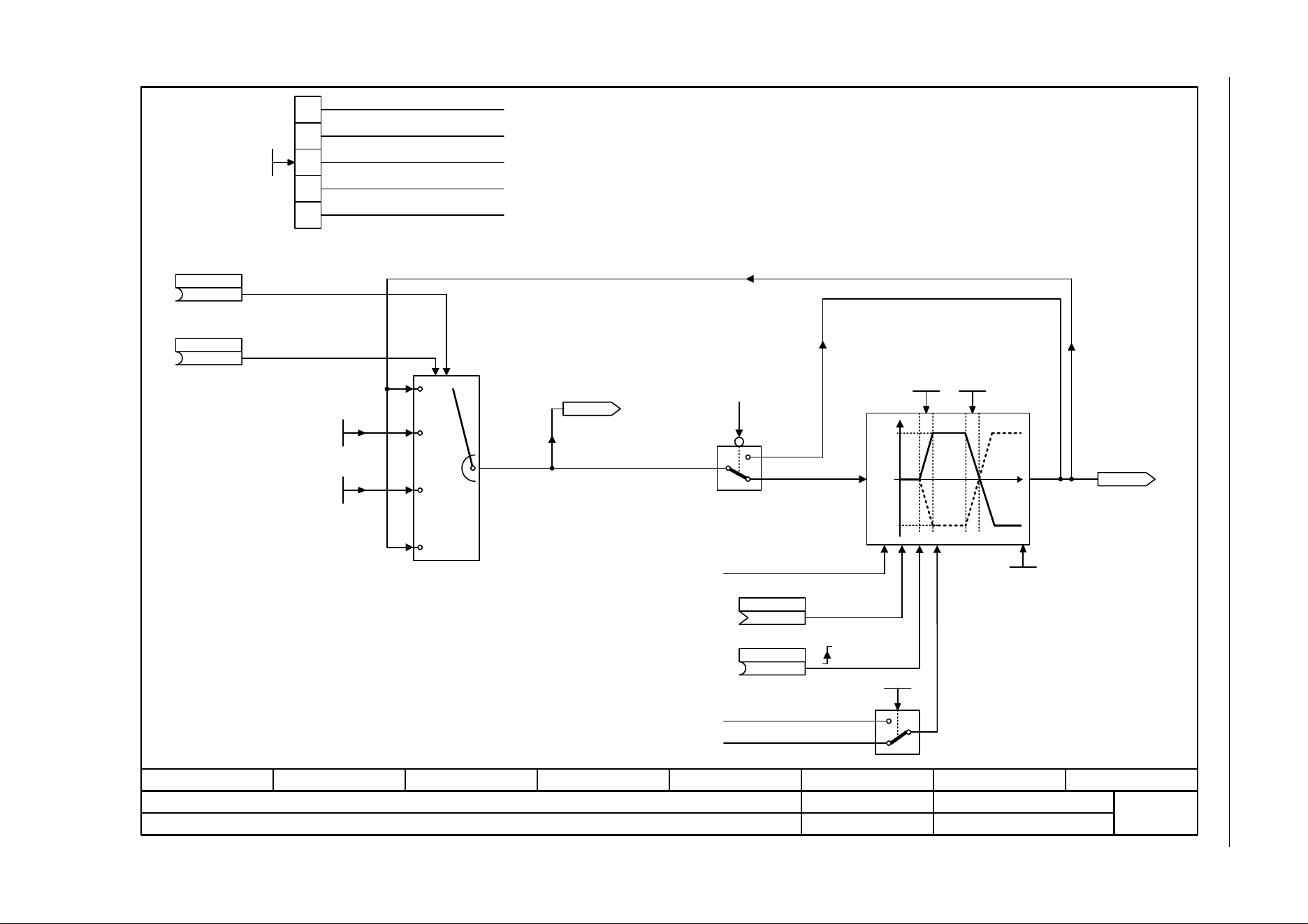
3 Function diagrams
3.12 Setpoint channel
SINAMICS G120C
398 List Manual (LH13), 04/2014, A5E33840768B AA
Fig. 3-66 3020 – Motorized potentiometer
- 3020 -
Function diagram
87654321
fp_3020_97_05.vsd
Setpoint channel
SINAMICS G120C
07.04.2014 V4.7
Motorized potentiometer
<1>
<1>
0 0
0 1
1 0
1 1
<1>
<3>
<3>
[3050.5]
xy
y
p1082
-p1082
x
y = 0
<2>
<2> <2>
0
1
Old value is kept
f_max (reference value for
ramp-function generator p1082)
For automatic commissioning, p1037 and p1038 are set to the
maximum motor frequency or to the rated motor frequency,
provided that f_max_mot has not been specified.
If initial rounding-off is active (p1025.2 = 1), the selected ramp-up/
down times are exceeded accordingly.
Only effective if p1025.0 = 0.
MotP n_max
-210000.000 ... 210000.000 [rpm]
p1037 [D] (0.000)
MotP n_min
-210000.000 ... 210000.000 [rpm]
p1038 [D] (0.000)
(0)
Mop raise
p1035 [C]
(0)
Mop lower
p1036 [C]
r1045
Mop n_set bef RFG [rpm]
Mop set val
(0)
p1044 [C]
(0)
MotP acc set val
p1043 [C]
Mop start value
-210000.000 ... 210000.000 [rpm]
p1040 [D] (0.000)
Mop ramp-down time
0.000 ... 1000.000 [s]
p1048 [D] (10.000)
Mop ramp-up time
0.000 ... 1000.000 [s]
p1047 [D] (10.000)
e.g. to [3030.1]
r1050
Mop setp after
RFG [rpm]
p1030.1
0
1
0
1
0
1
0
1
0
1
2
3
Data save active
Automatic mode Ramp-function
generator active
Initial rounding-off active
Save in NVRAM active
The setpoint for the motorized potentiometer is not saved and after ON is entered using p1040.
The setpoint for the motorized potentiometer is saved in a ashion after OFF and after ON set to the saved value.
Without ramp-function generator in automatic mode (ramp-up/ramp-down time = 0).
With ramp-function generator in automatic mode.
Without initial rounding.
With initial rounding. The ramp-up/down time set is exceeded accordingly.
Not saved in the NVRAM (NVRAM = Non Volatile Random Access Memory).
Save in NVRAM active.
4
Mop configuration
- ... -
p1030 [D] (0000 0110 bin)
[2634.8]
1: OFF1 enable missing (r0046.0)
0
1
p1030.4
0:
0
1
Ramp-function generator is always
active
Ramp-up encoder inactive with pulse inhibit.
The ramp-up encoder is calculated independently of the pulse enable.
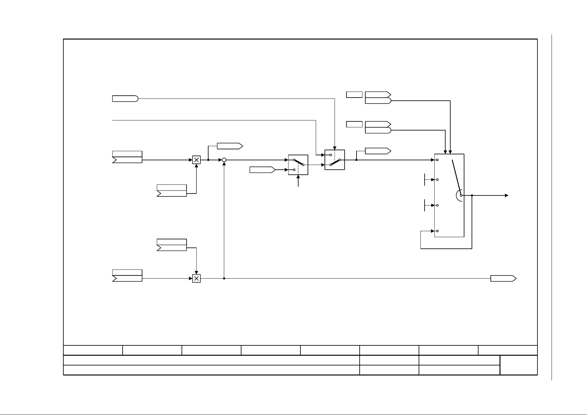
SINAMICS G120C
List Manual (LH13), 04/2014, A5E33840768B AA
399
3 Function diagrams
3.12 Setpoint channel
Fig. 3-67 3030 – Main/supplementary setpoint, setpoint scaling, jogging
- 3030 -
Function diagram
87654321
fp_3030_97_05.vsd
Setpoint channel
SINAMICS G120C
07.04.2014 V4.7
Main/supplementary setpoint, setpoint scaling, jogging
+
+
[2501.7]
p1055
[2501.7]
p1056
0
1
<1>
0 0
0 1
1 0
1 1
[3040.1]
<1>
Jogging can only be activated in the operating state “Ready for switching on“.
Keep old setpoint
n_set_1
Main setpoint
(755[0])
p1070 [C]
Main setp scal
(1)
p1071 [C]
Suppl setp scal
(1)
p1076 [C]
Suppl setp
(0)
p1075 [C]
PcCtrl active
r0807
.0
STW seq_ctrl
r0898
r0898
.8
STW seq_ctrl
r0898
r0898
.9
Jog 1 n_set
-210000.000 ... 210000.000 [rpm]
p1058 [D] (150.000)
Jog 2 n_set
-210000.000 ... 210000.000 [rpm]
p1059 [D] (-150.000)
r1078
Total setpoint eff [rpm]
1
0
Setpoint from external OP or operating tool
<2>
=1 if technology controller is activated (p2200 > 0, p2251 = 0).
<3> The connection to the source for the main and additional setpoint is estabished automatically via the setting in p1000.
<3>
<3>
r2294
Tec_ctrl outp_sig [%]
<2>
r1073
Main setpoint eff [rpm]
r1077
Suppl setpoint eff [rpm]
[7958.8]
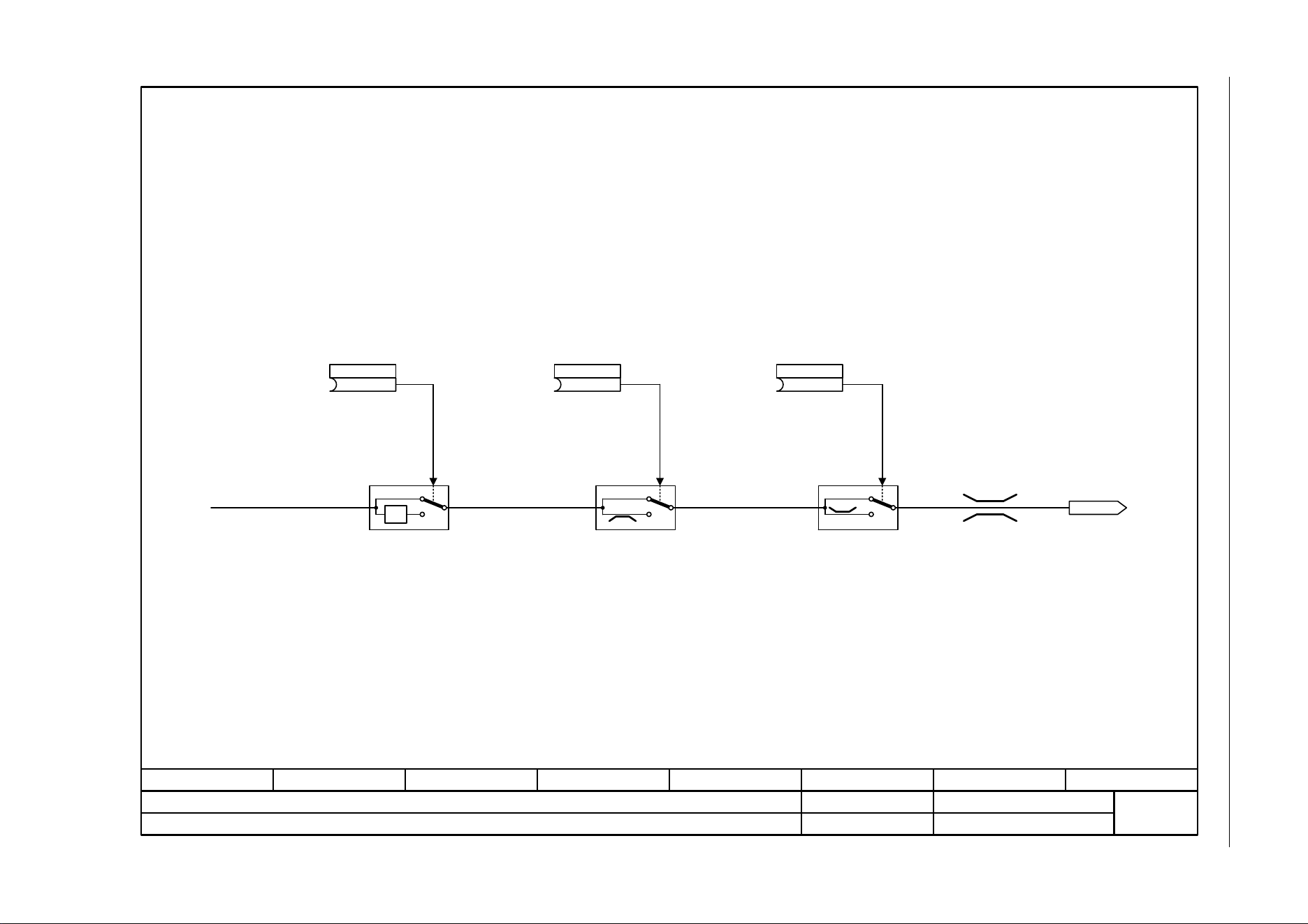
3 Function diagrams
3.12 Setpoint channel
SINAMICS G120C
400 List Manual (LH13), 04/2014, A5E33840768B AA
Fig. 3-68 3040 – Direction limitation and direction reversal
- 3040 -
Function diagram
87654321
fp_3040_97_05.vsd
Setpoint channel
SINAMICS G120C
07.04.2014 V4.7
Direction limitation and direction reversal
[3030.8] [3050.1]
-1
0
1
0
1
0
0
1
0
n_set_1
1 = Direction reversal 1 = Inhibit negative direction of
rotation
1 = Inhibit positive direction of
rotation
r1114
Setp after limit [rpm]
(722.1)
Setp inv
p1113 [C]
(0)
Inhib neg dir
p1110 [C]
(0)
Inhib pos dir
p1111 [C]
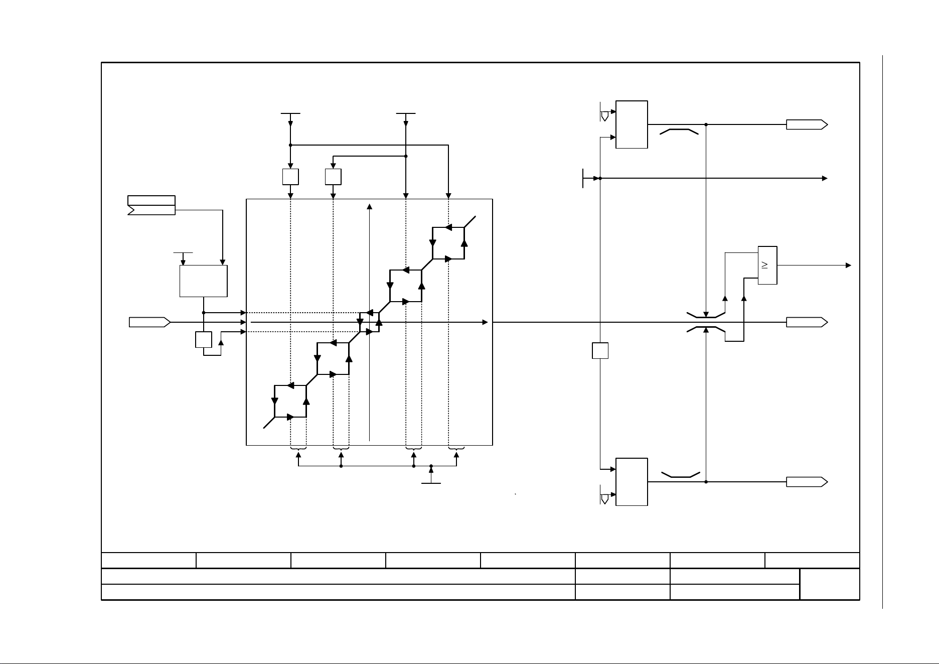
SINAMICS G120C
List Manual (LH13), 04/2014, A5E33840768B AA
401
3 Function diagrams
3.12 Setpoint channel
Fig. 3-69 3050 – Skip frequency bands and speed limitations
- 3050 -
Function diagram
87654321
fp_3050_97_05.vsd
Setpoint channel
SINAMICS G120C
07.04.2014 V4.7
Skip frequency bands and speed limitations
[3020.6]
[3070.4]
y
Max
-1
Min
<2>
1
[6030.1]
[6640.5]
[8010.2]
[6030.1]
[6640.5]
[8010.2]
0
0
Reference value for the ramp-
function generator
Limiting to
negative values
Maximum limiting
active
A suppression frequency of "0" de-activates the suppression frequency bandwidth.
n_skip 1
0.000 ... 210000.000 [rpm]
p1091 [D] (0.000)
n_limit pos
0.000 ... 210000.000 [rpm]
p1083 [D] (210000.000)
<1> <1>
<3>
w
-1 -1
y
x
n_skip 2
0.000 ... 210000.000 [rpm]
p1092 [D] (0.000)
<1>
The setting range of p1082 is limited to f_max_mot.
If the drive is not stopped via the input setpoint, but via controlled intervention, the lower
hysteresis branch is relevant after a subsequent run-up.
<2>
<3>
n_skip bandwidth
0.000 ... 210000.000 [rpm]
p1101 [D] (0.000)
n_limit neg
-210000.000 ... 0.000 [rpm]
p1086 [D] (-210000.000)
n_max
0.000 ... 210000.000 [rpm]
p1082 [D] (1500.000)
r1119
RFG setp at inp [rpm]
w
w
w
r1084
n_limit pos eff [rpm]
[3040.8]
r1114
Setp after limit [rpm]
-1
n_min
0.000 ... 19500.000 [rpm]
p1080 [D] (0.000)
n_min s_src
(0)
p1106 [C]
Max
r1087
n_limit neg eff [rpm]
[3070.1]
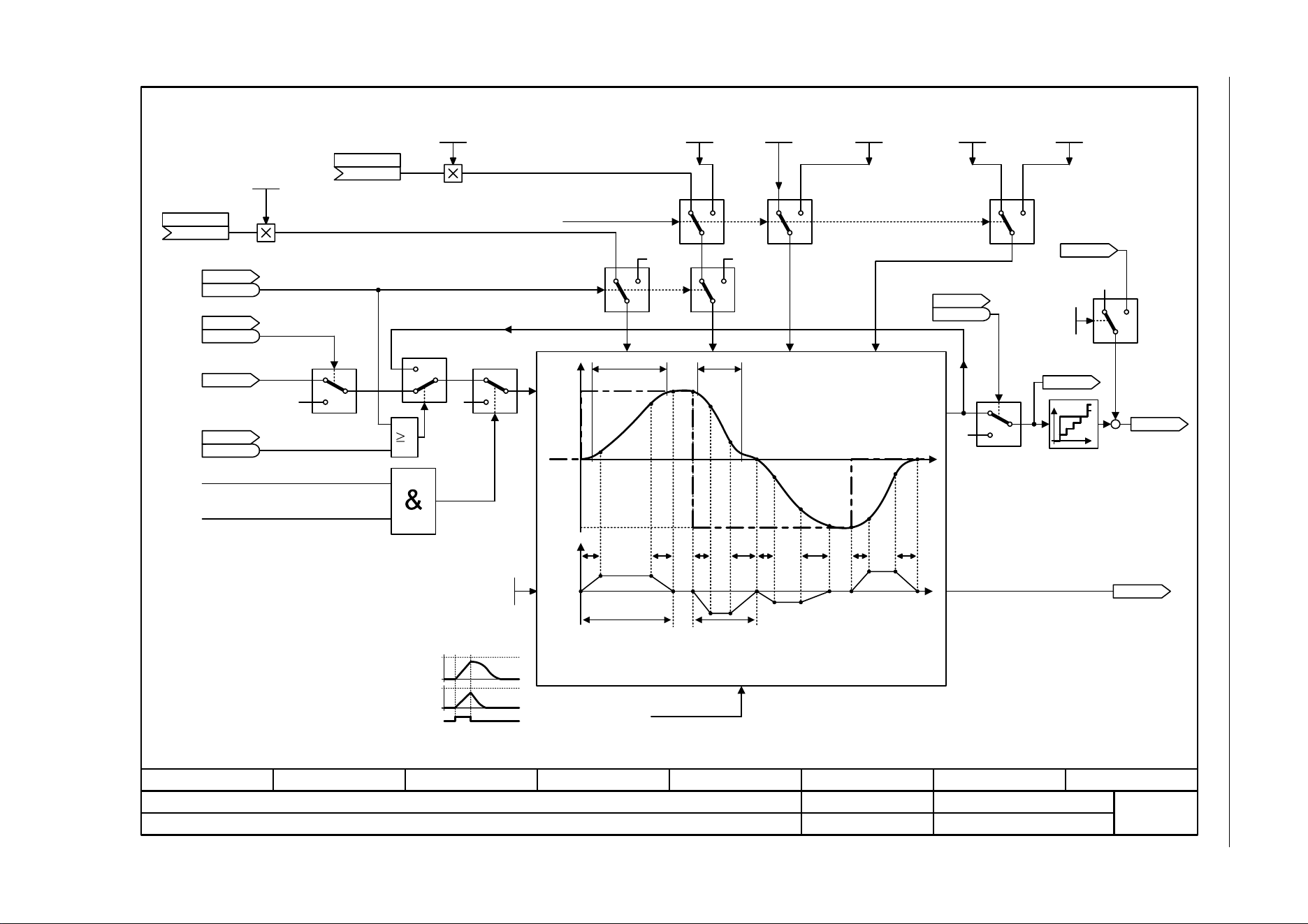
3 Function diagrams
3.12 Setpoint channel
SINAMICS G120C
402 List Manual (LH13), 04/2014, A5E33840768B AA
Fig. 3-70 3070 – Extended ramp-function generator
- 3070 -
Function diagram
87654321
fp_3070_97_05.vsd
Setpoint channel
SINAMICS G120C
07.04.2014 V4.7
Extended ramp-function generator
0
Tup
FRIRFRIRFRIRFRIR
Tdn
p1082
Tup_eff <2> Tdn_eff <2>
-p1082
IR FR
[3050.8]
0
p1082
x
y
<3>
[3050.5]
x
t
y
dy/dt
y
0 1 0 1 0 1
1
0
1
0
0
1
10 10
[6030.1]
0
1
0
1
0
0
<1>
t
n
soll
t
t
<2>
1 = Bypass ramp-function generator
STW setpoint chan
r1198
r1198
.15
STW seq_ctrl
r0898
r0898
.6
1 = Enable speed
setpoint
r1119
RFG setp at inp [rpm]
STW seq_ctrl
r0898
r0898
.5
0 = Freeze ramp-
function generator
1 = Internal RFG enable
0 = Internal quick stop
RFG round-off type
0 ... 1
p1134 [D] (0)
Freeze ramp-function generator
0 = Internal quick stop
RFG OFF3 t_end_del
0.000 ... 30.000 [s]
p1137 [D] (0.000)
STW seq_ctrl
r0898
r0898
.4
1 = Enable ramp-function generator
Effective ramp-up time: Tup_eff = Tup + (IR/2 + FR/2)
Effective ramp-down time: Tdn_eff = Tdn + (IR/2 + FR/2)
Rounding-off is always active.
Overshoots can occur.
Final rounding-off is not effective
when the setpoint is suddenly
reduced during ramp-up.
Extended ramp-function
generator
<4>
With activated Technology controller (p2200 > 0, p2251 = 0) the ramp-function generator is bypassed.
<4>
[2634.8]
[2634.8]
[2634.8]
Value range and/or factory setting depend on Power Module.
<1> Inhibited during jogging.
<5> <5> <5> <5>
<5>
[2501.7]
[2501.7]
r1170
n_ctrl setp sum
[rpm]
Interpolator
+
+
OFF3 t_RD
0.000 ... 5400.000 [s]
p1135 [D] (0.000)
RFG t_start_round
0.000 ... 30.000 [s]
p1130 [D] (0.000)
RFGOFF3 t_strt_rnd
0.000 ... 30.000 [s]
p1136 [D] (0.000)
RFG t_end_delay
0.000 ... 30.000 [s]
p1131 [D] (0.000)
r1150
RFG n_set at
outp [rpm]
0 1
Tec_ctrl mode
0 ... 1
p2251 (0)
r2294
Tec_ctrl outp_sig [%]
0
r1149
RFG acceleration [rev/
s²]
RFG ramp-up time
0.000 ... 999999.000 [s]
p1120 [D] (10.000)
RFG t_RU scal
(1)
p1138 [C]
<5>
RFG ramp-down time
0.000 ... 999999.000 [s]
p1121 [D] (10.000)
RFG t_RD scal
(1)
p1139 [C]
<3> p1134 = 0:
p1134 = 1:
t
Reference value for the ramp-
function generator

SINAMICS G120C
List Manual (LH13), 04/2014, A5E33840768B AA
403
3 Function diagrams
3.13 Vector control
3.13 Vector control
Function diagrams
6020 – Speed control and generation of the torque limits, overview 404
6030 – Speed setpoint, acceleration model 405
6040 – Speed controller 406
6060 – Torque setpoint 407
6220 – Vdc_max controller and Vdc_min controller 408
6300 – U/f control, overview 409
6301 – U/f characteristic and voltage boost 410
6310 – Resonance damping and slip compensation (U/f) 411
6320 – Vdc_max controller and Vdc_min controller (U/f) 412
6630 – Upper/lower torque limit 413
6640 – Current/power/torque limits 414
6700 – Current control, overview 415
6710 – Current setpoint filter 416
6714 – Iq and Id controllers 417
6721 – Id setpoint (PEM, p0300 = 2) 418
6722 – Field weakening characteristic, Id setpoint (ASM, p0300 = 1) 419
6723 – Field weakening controller, flux controller (ASM, p0300 = 1) 420
6724 – Field weakening controller (PEM, p0300 = 2) 421
6730 – Interface to the Power Module (ASM, p0300 = 1) 422
6731 – Interface to the Power Module (PEM, p0300 = 2) 423
6799 – Display signals 424
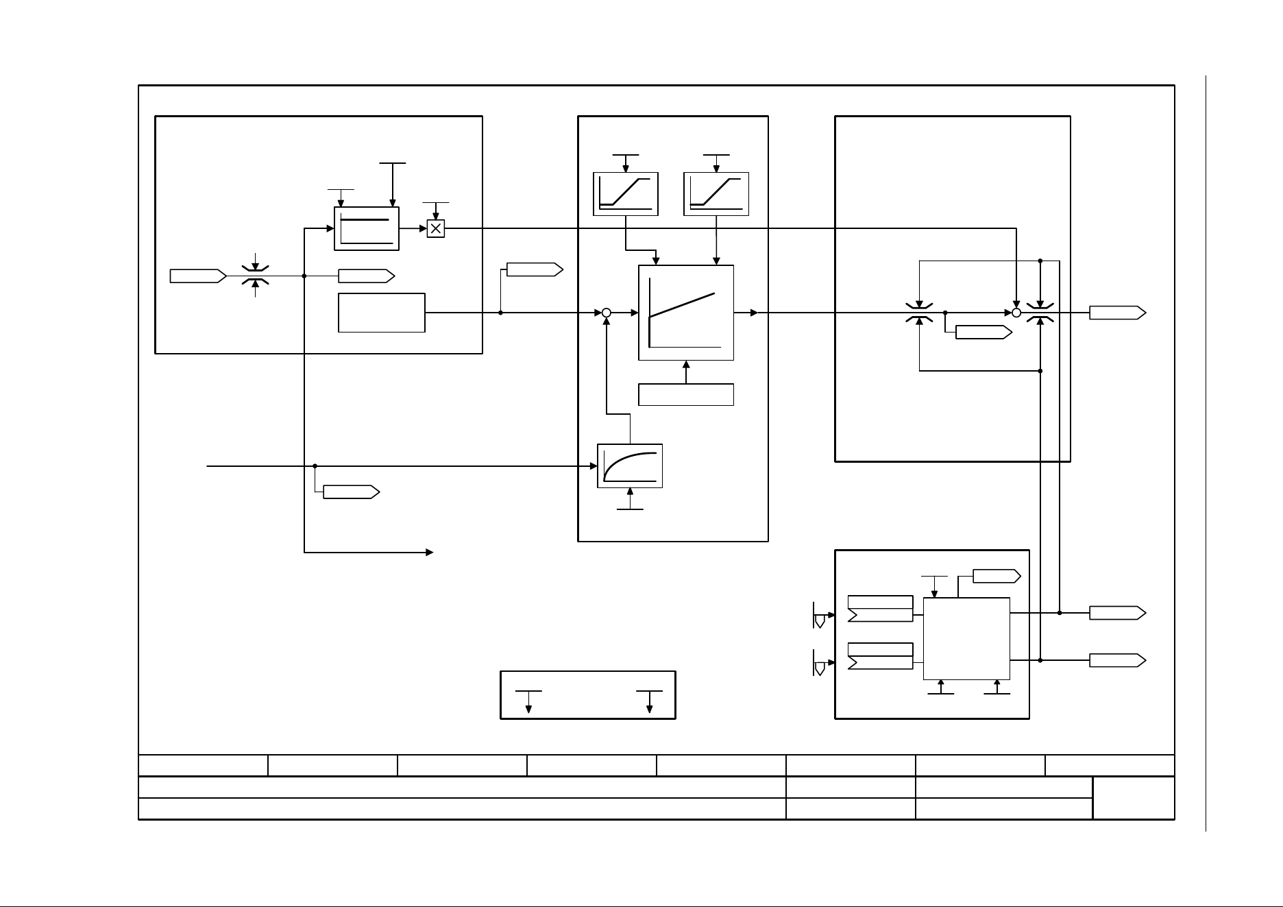
3 Function diagrams
3.13 Vector control
SINAMICS G120C
404 List Manual (LH13), 04/2014, A5E33840768B AA
Fig. 3-71 6020 – Speed control and generation of the torque limits, overview
- 6020 -
Function diagram
87654321
fp_6020_97_05.vsd
Vector control
SINAMICS G120C
07.04.2014 V4.7
Speed control and generation of the torque limits, overview
[6630] Upper/lower torque limit
[6640] Current/power/torque limits
[2526] Status word closed-loop control
[2530] Status word closed-loop current control
r0056 r1408
r0067
I_Ausg max
n_modell
–
[3001.8]
[6700.1]
Symmetrizing
Acceleration model
Speed controller
Torque setpoint
Generating the
torque limits
Speed setpoint
r0062
n_set after filter [rpm]
n_C n_act T_s SL
p1452
Mot M_mom of inert
p0341
Mot MomInert Ratio
p0342
n_ctrl SL Kp
p1470
n_ctrl SL Tn
p1472
r1508
M_set bef. M_suppl [Nm]
r0079
M_set [Nm]
r1538
M_max upper eff [Nm]
r1539
M_max lower eff [Nm]
M_max upper
(1520[0])
p1522 [C]
M_max lower
(1521[0])
p1523 [C]
P_max mot
p1530
P_max gen
p1531
Current limit
p0640
M_max upper
p1520 [D] (0.00)
M_max lower
p1521 [D] (0.00)
a_prectrl scal
p1496
[6030]
[6040]
[6060]
r0063[0..2]
n_act [rpm]
Integrator control
Kp Tn
r1170
n_ctrl setp sum
[rpm]
r1438
n_ctrl n_set
[rpm]
r1084
r1087
[3050]
[6700.1]
n_pre-control
Kp adaptation Tn adaptation
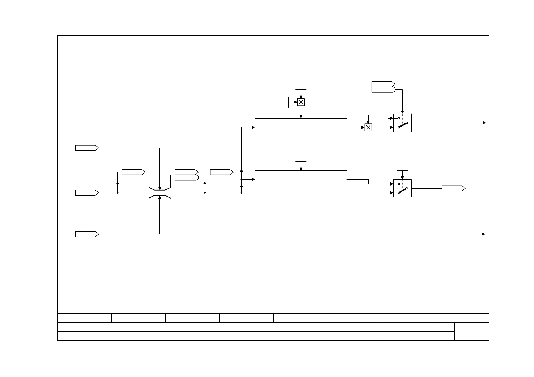
SINAMICS G120C
List Manual (LH13), 04/2014, A5E33840768B AA
405
3 Function diagrams
3.13 Vector control
Fig. 3-72 6030 – Speed setpoint, acceleration model
- 6030 -
Function diagram
87654321
fp_6030_97_05.vsd
Vector control
SINAMICS G120C
07.04.2014 V4.7
Speed setpoint, Acceleration model
[3050.8]
[6730.1]
[2522.3]
[2701.1]
[6799.1]
r0060
n_set before filt. [rpm]
r1170
n_ctrl setp sum [rpm]
ZSW n_ctrl
r1407
r1407
.11
Pre-control speed
r1084
n_limit pos eff [rpm]
r1087
n_limit neg eff [rpm]
[6060.1]
0
0
1
[2526.6]
[6040.1]
0
>0
Mot MomInert Ratio
1.000 ... 10000.000
p0342 [D] (1.000)
Mot M_mom of inert
0.000000 ... 100000.000000 [kgm²]
p0341 [D] (0.000000)
a_prectrl scal
0.0 ... 10000.0 [%]
p1496 [D] (0.0)
Acceleration calculation
ZSW cl-loop ctrl
r0056
r0056
.14
Calculated accelerating torque
r1438
n_ctrl n_set [rpm]
Pre-control balancing
n_C n_act T_s SL
0.00 ... 32000.00 [ms]
p1452 [D] (10.00)
a_prectrl scal
0.0 ... 10000.0 [%]
p1496 [D] (0.0)
[6799.1]
r0062
n_set after filter
[rpm]
[3070.8]
[3050.8]
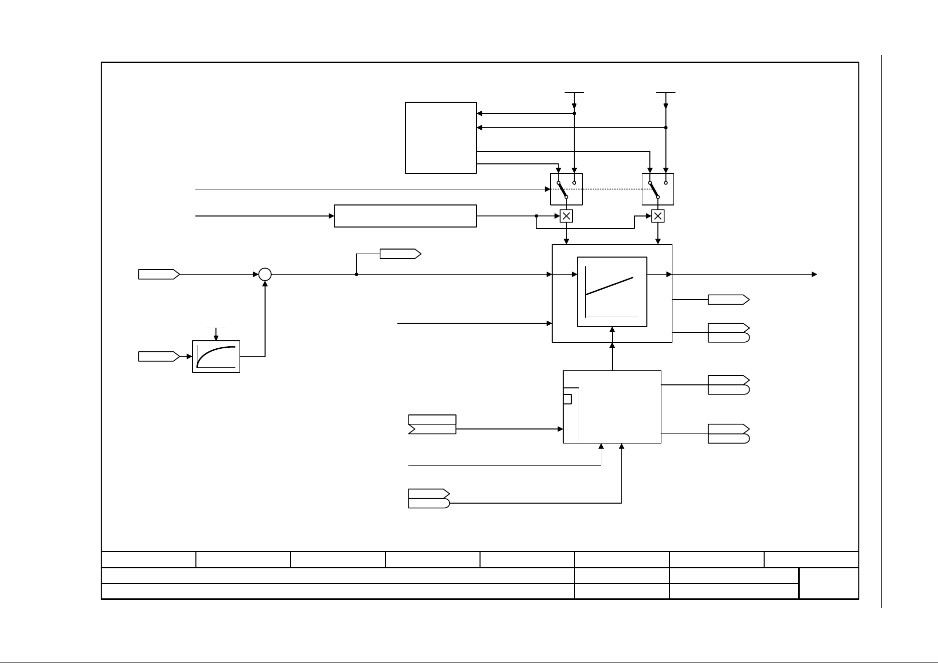
3 Function diagrams
3.13 Vector control
SINAMICS G120C
406 List Manual (LH13), 04/2014, A5E33840768B AA
Fig. 3-73 6040 – Speed controller
ZSW n_ctrl
r1407
r1407
- 6040 -
Function diagram
87654321
fp_6040_97_05.vsd
Vector control
SINAMICS G120C
07.04.2014 V4.7
Speed controller
[6030.8]
+
-
[6060.1]
[6030.1]
Kp_n_basic
Tn_n_basic
Tn_n_adapt
1 01 0
Kp_n_adapt
[2522.7]
[2522.3]
[2522.3]
Kp
<1>
Tn
[2522.3]
<1>
1 = Kp/Tn adaptation active
1 = Automatic Kp/Tn adaptation active
Dynamic reduction, field weakening
r0064
n_ctrl system dev [rpm]
r1438
n_ctrl n_set [rpm]
r0063
n_act [rpm]
n_C n_act T_s SL
0.00 ... 32000.00 [ms]
p1452 [D] (10.00)
Enable speed controller
from sequence control: Operation
.7
For p1472 = 0.0 s or 100.0 s, the I component is
inhibited (integral action time = infinite).
1 = Torque limit reached
Integrator control
Speed controller
n_ctrl SL Kp
0.000 ... 999999.000
p1470 [D] (0.300)
M_set from speed controller
1 = Speed controller active
ZSW n_ctrl
r1407
r1407
.5
1 = Speed controller, I component set
ZSW n_ctrl
r1407
r1407
.6
ZSW n_ctrl
r1407
r1407
.3
r1482
n_ctrl I-M_outp [Nm]
n_ctrl SL Tn
0.0 ... 100000.0 [ms]
p1472 [D] (20.0)
[6721.8]
Torque setting value, speed controller
n_ctrl M_sv MHB
(0)
p1475 [C]
Kp_n/Tn_n
adaptation
Kp Tn
1 = Speed controller, I component held
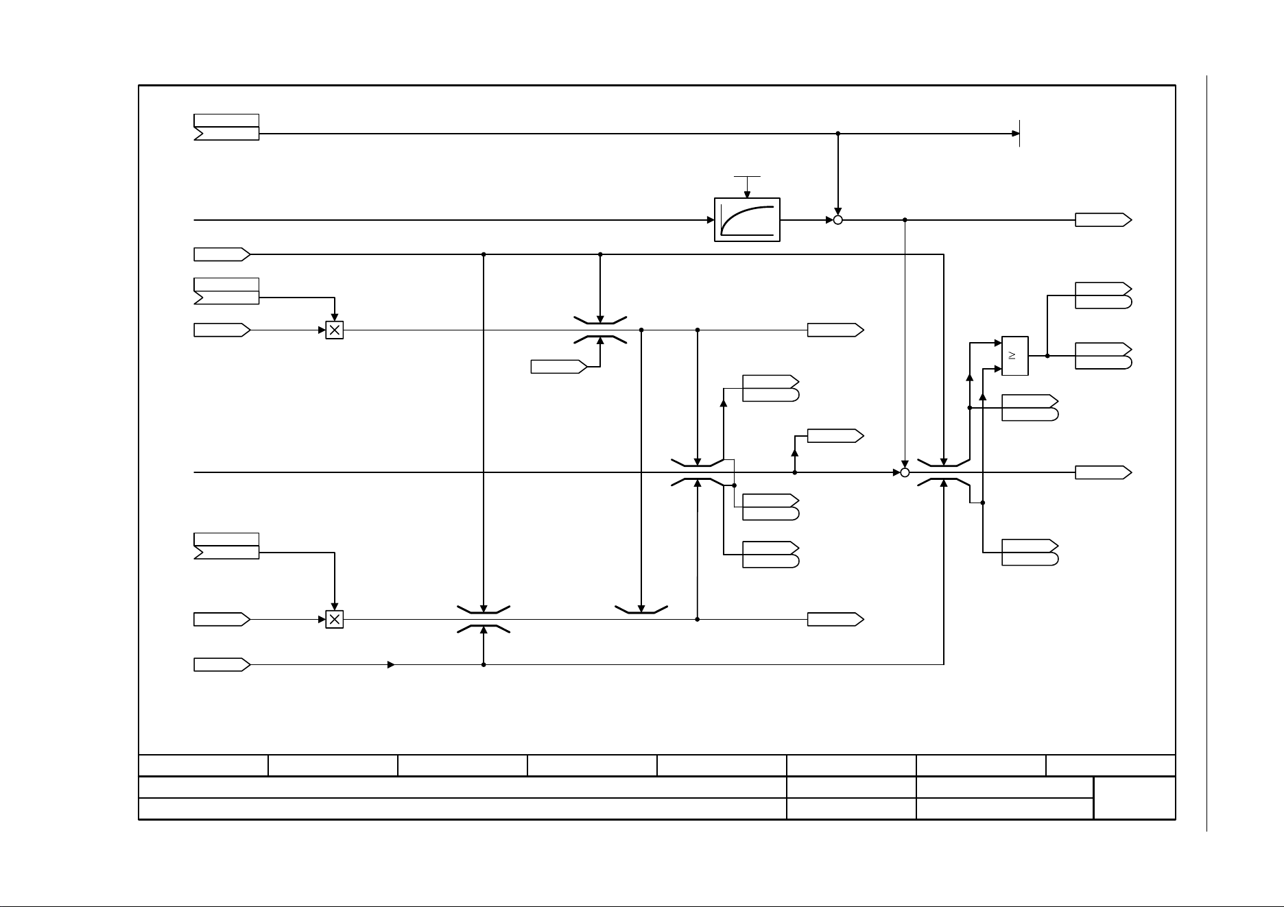
SINAMICS G120C
List Manual (LH13), 04/2014, A5E33840768B AA
407
3 Function diagrams
3.13 Vector control
Fig. 3-74 6060 – Torque setpoint
- 6060 -
Function diagram
87654321
fp_6060_97_05.vsd
Vector control
SINAMICS G120C
07.04.2014 V4.7
Torque setpoint
[6640.8]
[6710.1]
[8012.1]
[2522.3]
[2522.3]
[6640.8]
[2522.3]
[2522.3]
[2522.3]
+
+
[6722.1]
[6630.8]
[6630.8]
[6030.8]
1
[2526.2]
<1>
Calculated accelerating torque
r1538
M_max upper eff [Nm]
M_set from the speed controller
r1539
M_max lower eff [Nm]
Acceleration control is inhibited for p1517 = 100 ms.
M_accel T_smooth
0.00 ... 100.00 [ms]
p1517 [D] (4.00)
ZSW n_ctrl
r1407
r1407
r1508
M_set bef. M_suppl [Nm]
ZSW n_ctrl
r1407
r1407
.9
r1516
M_suppl + M_accel [Nm]
ZSW cl-loop ctrl
r0056
r0056
ZSW n_ctrl
r1407
r1407
ZSW n_ctrl
r1407
r1407
r0079
M_set [Nm]
ZSW n_ctrl
r1407
r1407
Torque limiting
r1539
M_max lower eff [Nm]
<2>
<1>
M_set is also influenced by the speed limit controller.
<2>
r1526
M_max up w/o offs [Nm]
r1527
M_max low w/o offs [Nm]
r1547
M_max outp n_ctrl [Nm]
[0]
r1547
M_max outp n_ctrl [Nm]
[1]
ZSW n_ctrl
r1407
r1407
M_max low w/o offs
(1)
p1554 [C]
M_max up w/o offs
(1)
p1552 [C]
[6040.8]
.15
.8
.8
.9
.13
.7
M_suppl 1
(0)
p1511 [C]
+
+
[Nm]
r1515
[6640.8]
[6721.1]
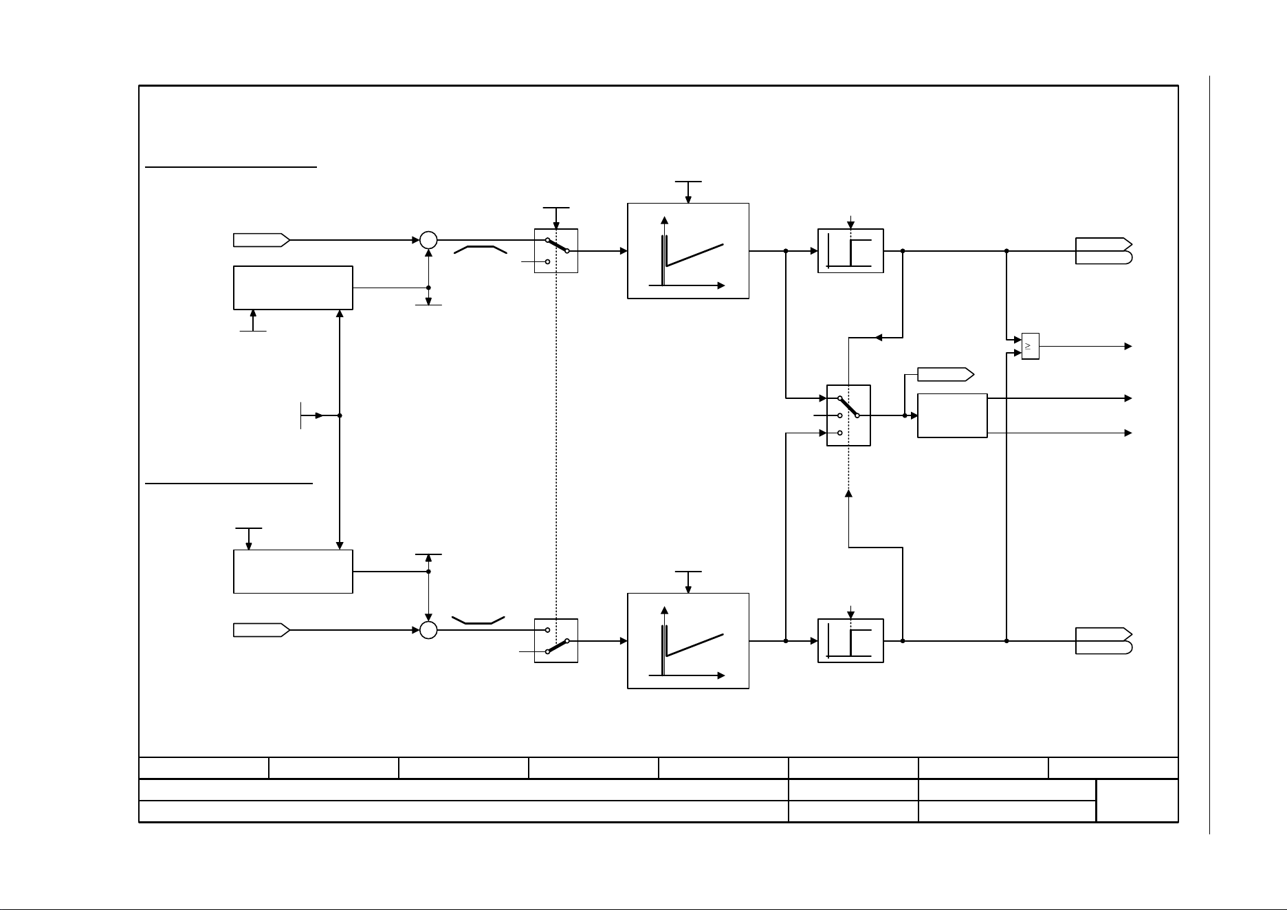
3 Function diagrams
3.13 Vector control
SINAMICS G120C
408 List Manual (LH13), 04/2014, A5E33840768B AA
Fig. 3-75 6220 – Vdc_max controller and Vdc_min controller
- 6220 -
Function diagram
87654321
fp_6220_97_05.vsd
Vector control
SINAMICS G120C
07.04.2014 V4.7
Vdc_max controller and Vdc_min controller (Vector)
0
1
1,3
0,2
–
+
0
1
–
+
0
Iq_max
[6710.2]
Iq_min
[6710.1]
[6710.1]
1
0
0
2,3
0,1
[2526.2]
[2526.2]
0
0
0
0
Calculate on_level
r0070
Vdc act val [V]
Vdc_max on_level [V]
r1242
V_connect
1 ... 63000 [V]
p0210 (400)
Vdc_min on_level [V]
r1246
r0070
Vdc act val [V]
r1258
Vdc_ctrl output [Arms]
Operating point
selection
Vdc controller
active
ZSW cl-loop ctrl
r0056
r0056
ZSW cl-loop ctrl
r0056
r0056
.15
Calculate on_level
Vdc_max (Vector control)
Vdc_min (Vector control)
.14
Vdc_min dyn_factor
p1247 [D]
Vdc_max dyn_factor
p1243 [D]
Vdc ctr config vec
p1240 [D]
Vdc_min on_level
p1245 [D]
Vdc_max SenseOnLev
p1254
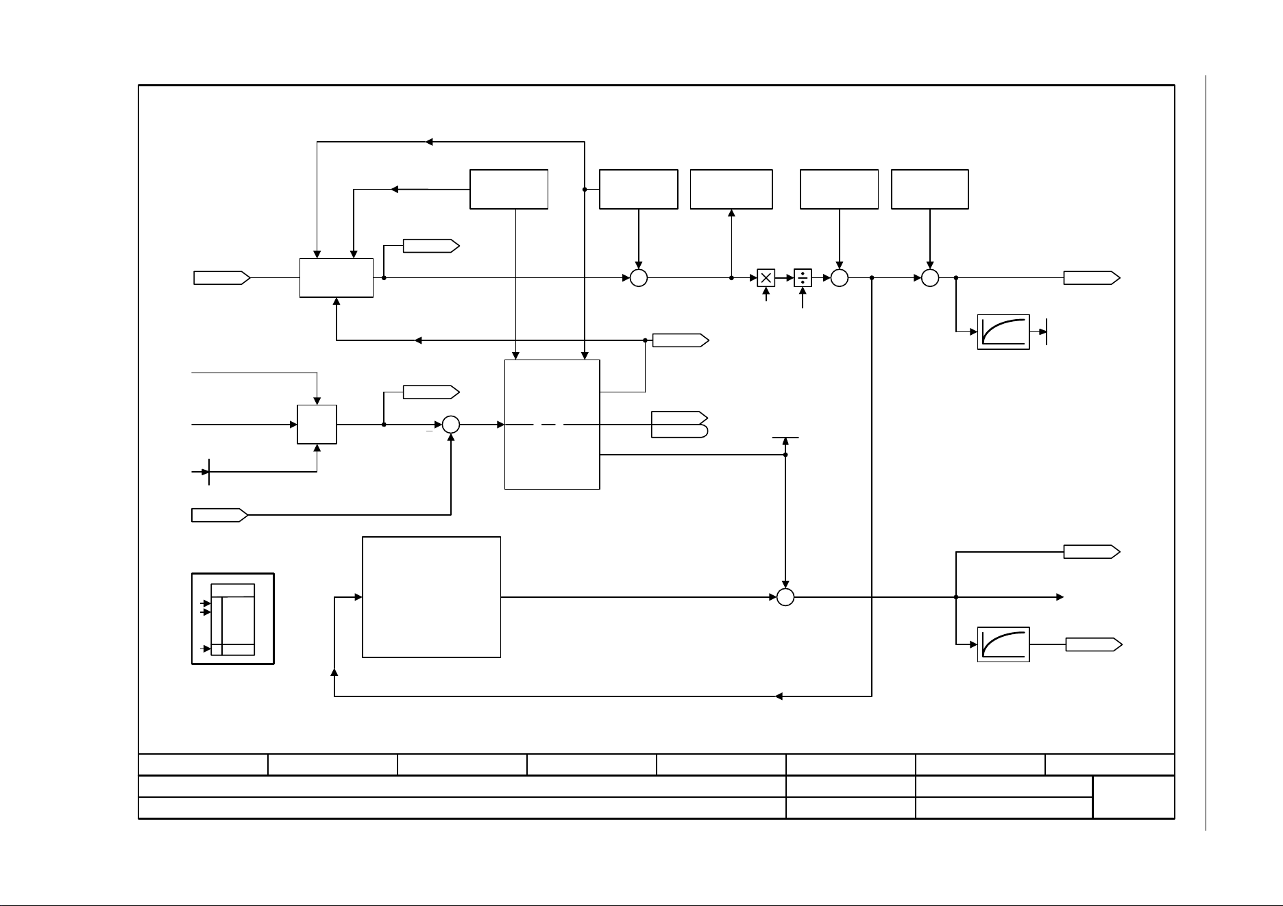
SINAMICS G120C
List Manual (LH13), 04/2014, A5E33840768B AA
409
3 Function diagrams
3.13 Vector control
Fig. 3-76 6300 – U/f control, overview
Imax closed-loop
frequency control
p1340 ... p1341
Imax closed-loop
voltage control
p1345 ... P1346
- 6300 -
Function diagram
87654321
fp_6300_97_05.vsd
Vector control
SINAMICS G120C
07.04.2014 V4.7
U/f control, overview
[6310]
[6320]
[6310]
[6310]
[3050.8]
[8016.8]
[6730.4]
[6714.8]
[6730.1]
60
[6301.8]
100 ms
100 ms
[6030.1]
[3070]
MIN
r0056
.
.
.
[2526]
Ramp-function
generator
I_max reduction
I_max Power Module
f_set
r1119
RFG setp at inp [rpm]
r1170
n_ctrl setp sum [rpm]
I_max_ctrl U_outp [Vrms]
r1344
r0066
f_outp [Hz]
f_outp smooth [Hz]
r0024
r0025
U_outp smooth [Vrms]
r0072
U_output [Vrms]
Vdc_ctrl config
p1280
Flying restart
mode
p1200
Speed actual
value calculation
Slip
compensation
p1334, p1335
Uf Res_damp
gain
p1338
Control mode
p1300
V_boost perm
p1310
[6301]
ZSW cl-loop ctrl
r0056
r0056
.13
PU P_rated [kW]
r0206
[2]
r1343
I_max_ctrl f_outp [rpm]
r0067
I_outp max [Arms]
r0068
I_act abs val [Arms]
[0]
V_boost accelerate
p1311
V_boost starting
p1312
Motor pole pair
number
Eco mode
+
++
++
+
+
+
+
V_set
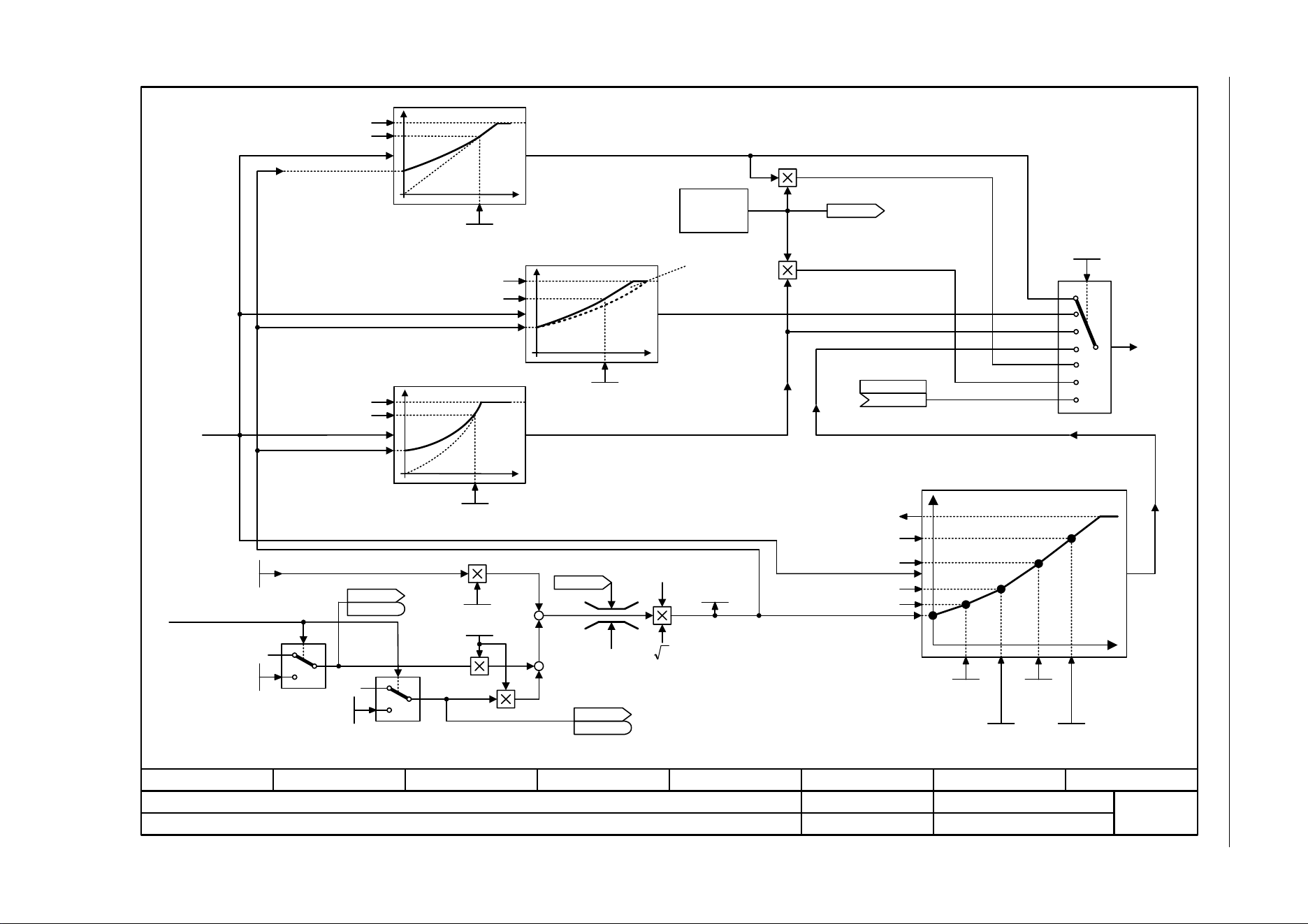
3 Function diagrams
3.13 Vector control
SINAMICS G120C
410 List Manual (LH13), 04/2014, A5E33840768B AA
Fig. 3-77 6301 – U/f characteristic and voltage boost
- 6301 -
Function diagram
87654321
fp_6301_97_05.vsd
Vector control
SINAMICS G120C
07.04.2014 V4.7
U/f characteristic and voltage boost
0
1
0
0
<1>
<1>
1
0
0
<2>
For p1320 = 0, the voltage boost via p1310 is not effective.
p1312 is only active at the first acceleration after pulse enable.
Freely programmable
ZSW cl-loop ctrl
r0056
r0056
Mot I_rated
p0305
ZSW cl-loop ctrl
r0056
r0056
U_boost total
r1315
R_stator act
r0395
Uf char U4 p1327
Uf char U3 p1325
Uf char U1 p1321
Uf char U2 p1323
Uf char f1
p1320
Uf char f2
p1322
Uf char f4
p1326
Uf char f3
p1324
U_output max r0071
3
r0067
I_outp max [Arms]
<2>
+
+
+
+
.6
.5
I_start accel
p1311
I_start start
p1312
I_start (Ua) perm
p1310
[2526.2]
[2526.2]
[6300.4]
[6300.2]
1/6
2
3
7
19
0/5
4
Parabolic
f_set
Uf U_set independ.
(0)
p1330 [C]
Op/cl-lp ctrl_mode
0 ... 20
p1300 [D] (0)
Mot U_rated p0304
U_output max r0071
Mot U_rated p0304
Mot U_rated p0304
Mot f_rated [Hz]
p0310 [D] (0.00)
Mot f_rated [Hz]
p0310 [D] (0.00)
Mot f_rated [Hz]
p0310 [D] (0.00)
U_output max r0071
U_output max r0071
r1348
U/f Eco fac act v [%]
Eco Mode
Dependent on the load
current
Flux current control (FCC)
Linear
from ramp-function
generator
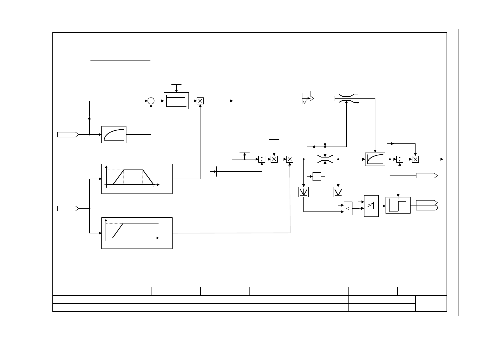
SINAMICS G120C
List Manual (LH13), 04/2014, A5E33840768B AA
411
3 Function diagrams
3.13 Vector control
Fig. 3-78 6310 – Resonance damping and slip compensation (U/f)
- 6310 -
Function diagram
87654321
fp_6310_97_05.vsd
Vector control
SINAMICS G120C
07.04.2014 V4.7
Resonance damping and slip compensation (U/f)
–
+
[6730.4]
[6731.4]
[6714.8]
-1
0
1
[6300.7]
250 ms
6 %
10 % 95 %
1
[2526.2]
<1>
<1>
0
p1334
f/f
Mot N
1
p1334 + 4 %
f/f
Mot N
U/f resonance damping
U/f slip compensation
If p1349 = 0: the limit is 0,95 x f Mot N <= 45 Hz.
r0078
Iq_act [Arms]
Uf Res_damp gain
0.00 ... 100.00
p1338 [D] (0.00)
f_res damp
r0066
f_outp [Hz]
Slip comp lim val
0.00 ... 600.00 [%]
p1336 [D] (250.00)
ZSW cl-loop ctrl
r0056
r0056
.10
Brake f_start
-300.00 ... 300.00 [%]
p1351 [D] (0.00)
Brake f_start
(1351[0])
p1352 [C]
<2>
Activation with r0056.4 = 1 till r0066 >= p1334 and p1216 has expired.
100 % equal r0330 (Rated motor slip)
<2>
20 ms
Slip
compensation
[6730.2]
f_Slip [Hz]
r0065
Slip comp scal
0.0 ... 600.0 [%]
p1335 [D] (0.0)
Mot slip_rated [Hz]
r0330 [D]
[6300.6]
Mot slip_rated [Hz]
r0330 [D]
100 %
r1337
Slip comp act val [%]
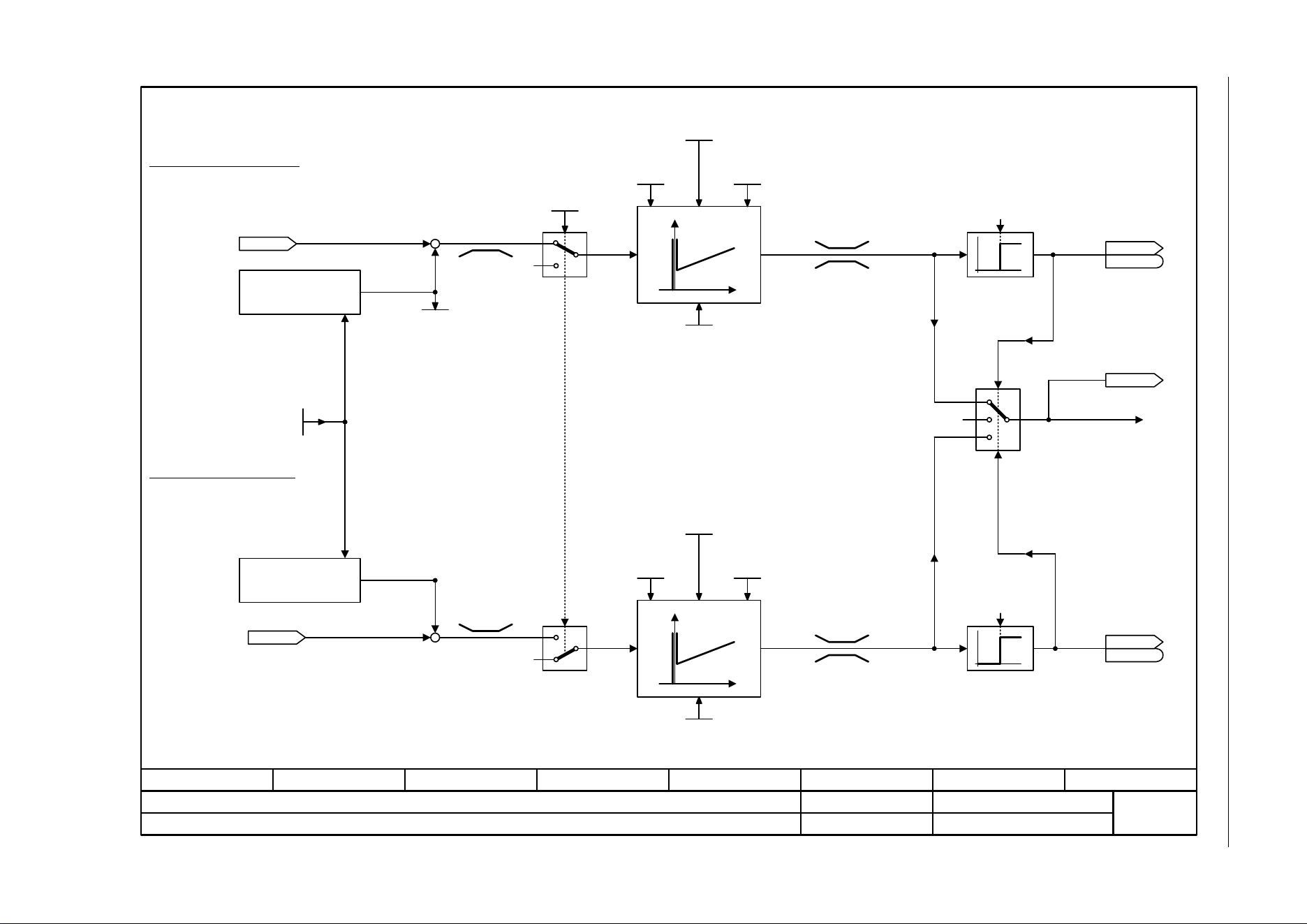
3 Function diagrams
3.13 Vector control
SINAMICS G120C
412 List Manual (LH13), 04/2014, A5E33840768B AA
Fig. 3-79 6320 – Vdc_max controller and Vdc_min controller (U/f)
- 6320 -
Function diagram
87654321
fp_6320_97_05.vsd
Vector control
SINAMICS G120C
07.04.2014 V4.7
Vdc_max controller and Vdc_min controller (U/f)
0
1
1,3
0,2
0
1
0
0
0
2,3
0,1
0
0
0
0
Calculate on_level
r0070
Vdc act val [V]
Vdc_max on_level [V]
r1282
r0070
Vdc act val [V]
r1298
Vdc_ctrl output [rpm]
ZSW cl-loop ctrl
r0056
r0056
ZSW cl-loop ctrl
r0056
r0056
Calculate on_level
Vdc_ctr config U/f
0 ... 1
p1280 [D] (1)
Vdc_max (U/f control)
Vdc_min (U/f control)
0
[6300.4]
–
+
Vdc_ctrl Kp
p1290 [D]
Vdc_ctrl t_rate
p1292 [D]
Vdc_ctrl Tn
p1291 [D]
Vdc_max dyn_factor
p1283 [D]
Vdc_ctrl Kp
p1290 [D]
Vdc_ctrl t_rate
p1292 [D]
Vdc_ctrl Tn
p1291 [D]
Vdc_min dyn_factor
p1287 [D]
V_connect
p0210
–
+
0
[2526.2]
.15
[2526.2]
.14
Vdc_ctrl config
600 Hz
600 Hz
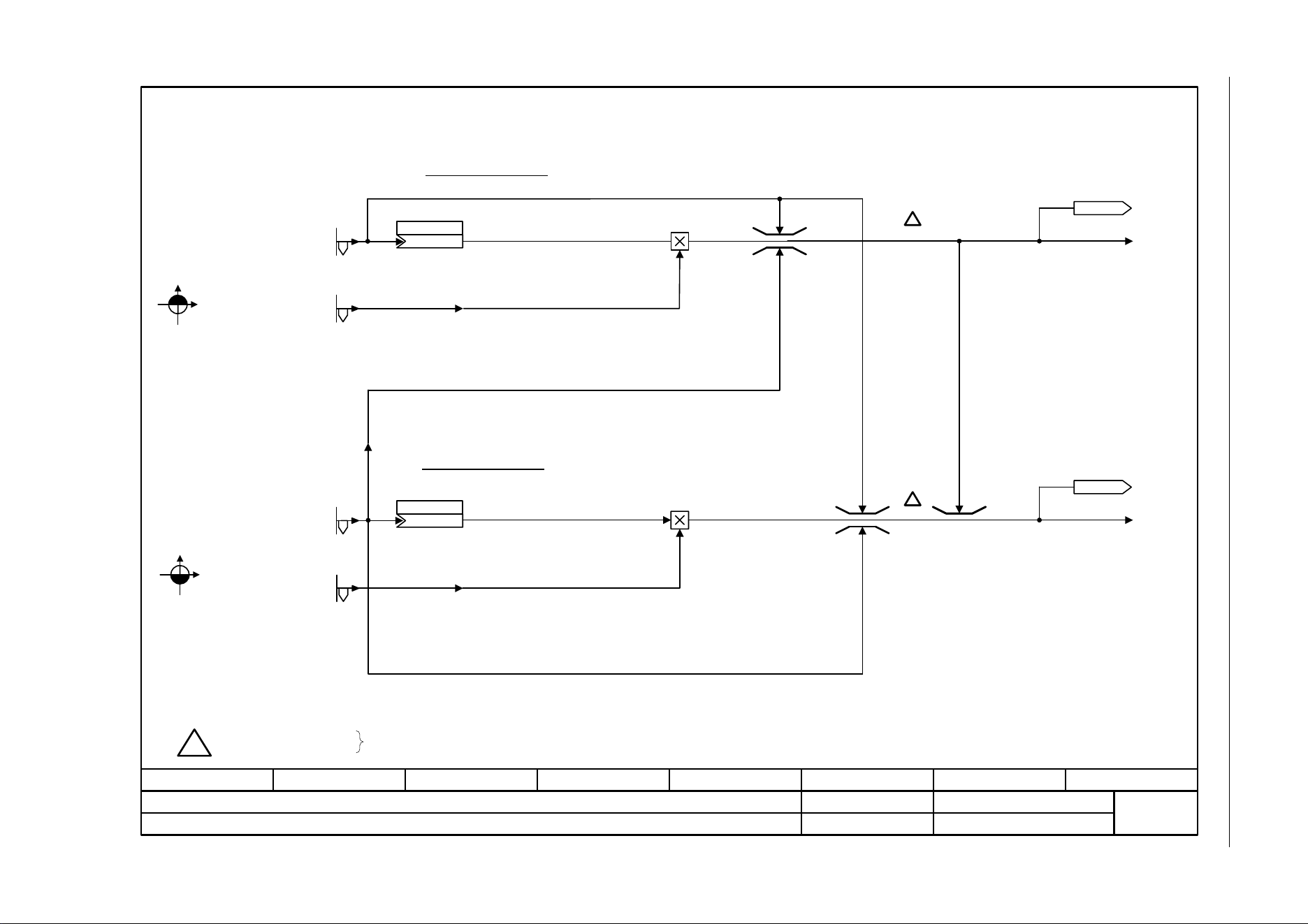
SINAMICS G120C
List Manual (LH13), 04/2014, A5E33840768B AA
413
3 Function diagrams
3.13 Vector control
Fig. 3-80 6630 – Upper/lower torque limit
- 6630 -
Function diagram
87654321
fp_6630_97_05.vsd
Vector control
SINAMICS G120C
07.04.2014 V4.7
Upper/lower torque limit
M
n
43
M
n
21
[6640.1]
[6640.1]
<1>
<1>
!
Upper torque limit
Lower torque limit
Danger: Negative values at <1>
positive values at <2>
represent a minimum torque for the other torque direction and can cause the motor to accelerate uncontrollably.
M_max upper
-1000000.00 ... 20000000.00 [Nm]
p1520 [D] (0.00)
M_max upper
(1520[0])
p1522 [C]
M_max lower
(1521[0])
p1523 [C]
<2>
<2>
!
!
M_max lower
-20000000.00 ... 1000000.00 [Nm]
p1521 [D] (0.00)
M_max lower scal
-2000.0 ... 2000.0 [%]
p1525 [D] (100.0)
M_max upper scal
-2000.0 ... 2000.0 [%]
p1524 [D] (100.0)
r1526
M_max up w/o offs [Nm]
r1527
M_max low w/o offs [Nm]
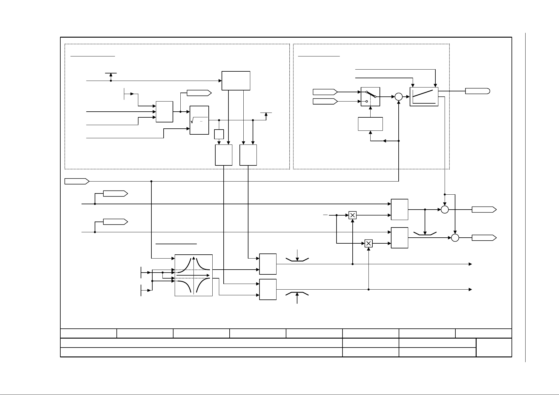
3 Function diagrams
3.13 Vector control
SINAMICS G120C
414 List Manual (LH13), 04/2014, A5E33840768B AA
Fig. 3-81 6640 – Current/power/torque limits
- 6640 -
Function diagram
87654321
fp_6640_97_05.vsd
Vector control
SINAMICS G120C
07.04.2014 V4.7
Current/power/torque limits
<1>
Iq
M
22
yx
-1
Min
Max Min
Min
Min
Max
+
–
+
+
+
[6722.1]
[6723.4]
[6724.4]
[6630.8]
[6630.8]
[6721.8]
[6730.1]
[6060.1] [6040.4]
[8012.1]
[6710.1]
[3050.8]
–
<1>
[8016.8]
[6730.4]
[6731.4]
[6723.8]
[6722.1]
x
y
[6060.1] [6040.4]
[8012.1]
+
+
<2>
<1>
Max
[6710.1]
[3050.8]
n
Iq
Current limiting
I_max reduction
I_max Power Module
Id_set total
Power limiting
Iq stall
calculation
Intervention by the Vdc controller.
Intervention when the speed limit is exceeded + 2 % n_rated.
Speed limiting
Kp from speed controller [6040.5]
Tn from speed controller [6040.6]
Speed limiting
controller
U_output max [Vrms]
r0071
Iq_max total [Arms]
r1533
Current limit
0.00 ... 10000.00 [Arms]
p0640 [D] (0.00)
P_max gen
-100000.00 ... -0.01 [kW]
p1531 [D] (-0.01)
P_max mot
0.00 ... 100000.00 [kW]
p1530 [D] (0.00)
r1538
M_max upper eff [Nm]
r1539
M_max lower eff [Nm]
r1084
n_limit pos eff [rpm]
r1087
n_limit neg eff [rpm]
r1527
M_max low w/o offs [Nm]
r1526
M_max up w/o offs [Nm]
r0067
I_outp max [Arms]
r0063
n_act [rpm]
[0]
Sign
+ or -
r1407.17
[2522.3]
1 = Speed limiting control
active
<2>
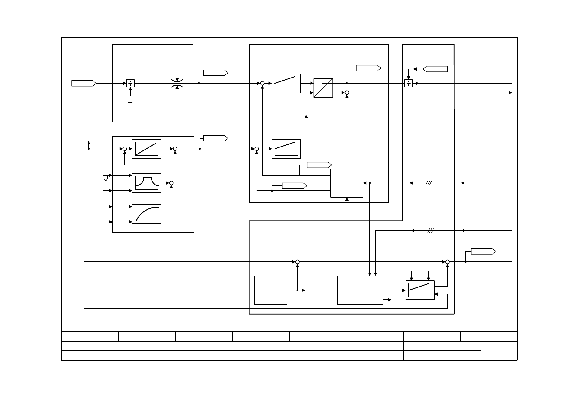
SINAMICS G120C
List Manual (LH13), 04/2014, A5E33840768B AA
415
3 Function diagrams
3.13 Vector control
Fig. 3-82 6700 – Current control, overview
- 6700 -
Function diagram
87654321
fp_6700_97_05.vsd
Vector control
SINAMICS G120C
07.04.2014 V4.7
Current control, overview
Iq
M
–
–
Iq
M
K
P
p1764 p1767
+
+
+
[6020.3]
[6020.1]
[6020.8]
[6722.1]
[6723.4]
[6724.4]
[6710] Current setpoint filter
Field weakening
controller
Field weakening
characteristic
Current calculation
[6722] Field weakening characteristic, Id setpoint
[6723] Field weakening control, flux controller for induction motors (p0300 = 1)
[6724] Field weakening controller for synchronous motors (p0300 = 2)
n_pre-control
n_model
iq controller
id controller
[6714] Current controller
Transformation
Current model Motor model
[6730] Interface to the Power Module for an induction motor (p0300 = 1)
[6731] Interface to the Power Module for a synchronous motor (p0300 = 2)
I_phase actual value
V_phase actual value
r0079
M_set [Nm]
U_output max [Vrms]
r0071
r0075
Id_set [Arms]
r0078
Iq_act [Arms]
r0076
Id_act [Arms]
r0072
U_output [Vrms]
r0070
Vdc act val [V]
r0066
f_outp [Hz]
r0077
Iq_set [Arms]
f_Slip [Hz]
r0065
Flex setp
50.0 ... 200.0 [%]
p1570 [D] (100.0)
V_set
Efficiency opt.
0 ... 100 [%]
p1580 [D] (0)
M_set static
-200.0 ... 200.0 [%]
p1610 [D] (50.0)
M_suppl_accel
0.0 ... 200.0 [%]
p1611 [D] (30.0)
U_angle
U_set
+
+
+
+
+
+
–
–
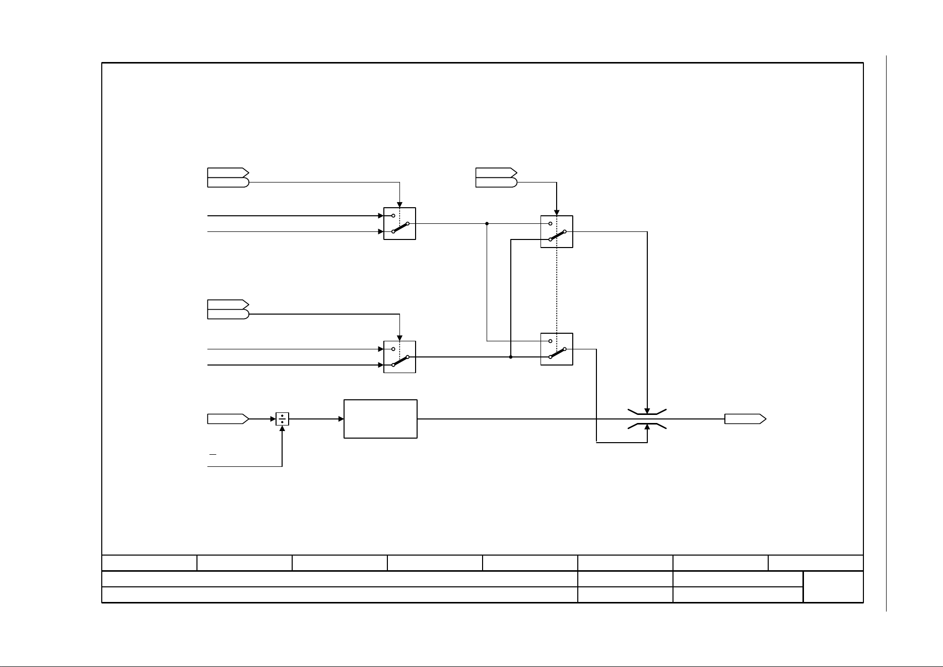
3 Function diagrams
3.13 Vector control
SINAMICS G120C
416 List Manual (LH13), 04/2014, A5E33840768B AA
Fig. 3-83 6710 – Current setpoint filter
- 6710 -
Function diagram
87654321
fp_6710_97_05.vsd
Vector control
SINAMICS G120C
07.04.2014 V4.7
Current setpoint filter
Iq
M
Iq_max
Iq_min
[6060.8]
[6640.8]
[6220.8]
[6220.8]
[2526.6]
[6640.8]
[6721.1]
[6730.1]
[6714.1]
0
1
0
1
[2526.6]
ZSW cl-loop ctrl
r0056
r0056
ZSW cl-loop ctrl
r0056
r0056
.15
r0079
M_set [Nm]
r0077
Iq_set [Arms]
Interpolator and
smoothing for
voltage limits
0
1
1
0
[2526.6]
ZSW cl-loop ctrl
r0056
r0056
.14 .7
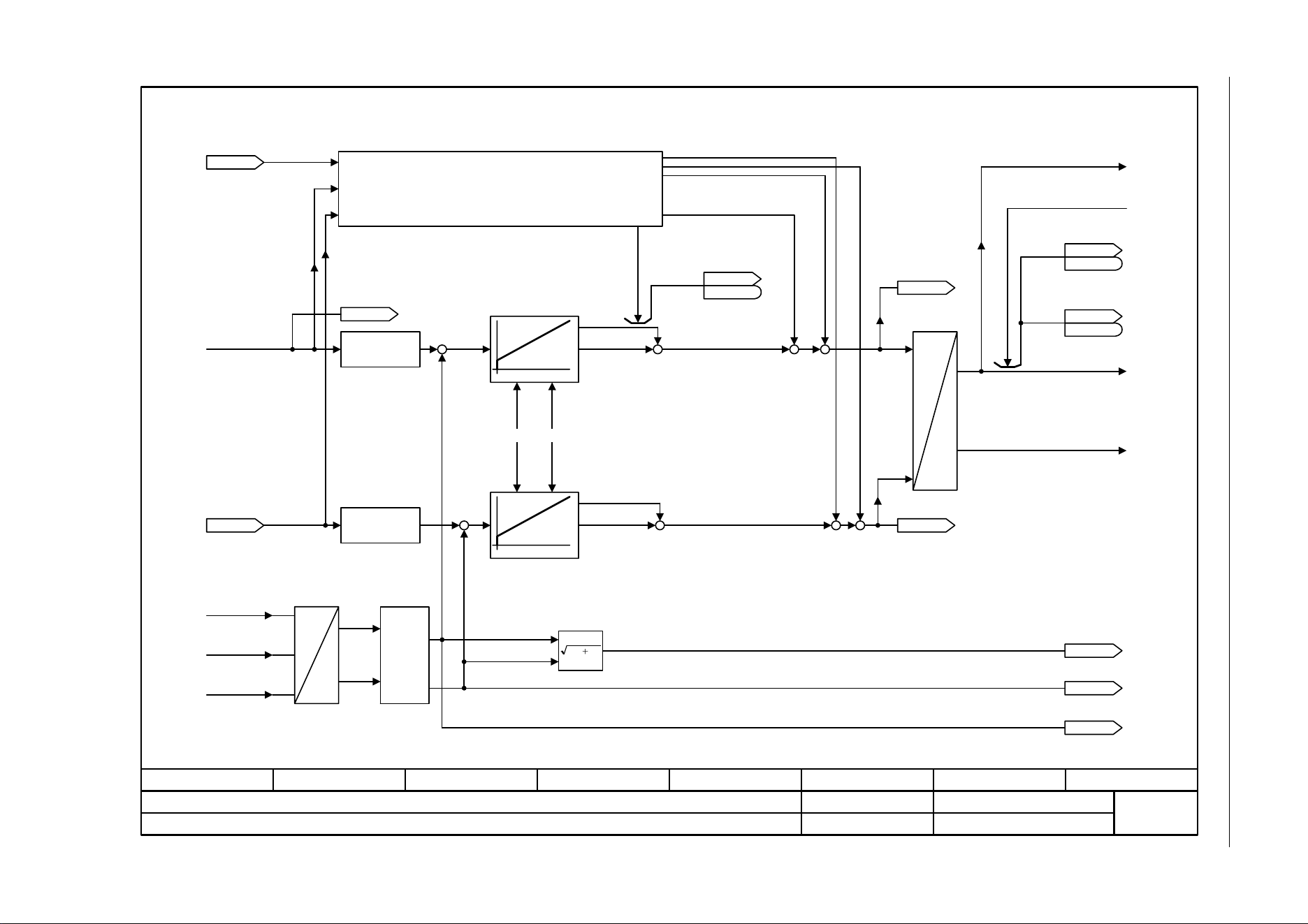
SINAMICS G120C
List Manual (LH13), 04/2014, A5E33840768B AA
417
3 Function diagrams
3.13 Vector control
Fig. 3-84 6714 – Iq and Id controllers
- 6714 -
Function diagram
87654321
fp_6714_97_05.vsd
Vector control
SINAMICS G120C
07.04.2014 V4.7
Iq and Id controllers
[2530.2]
Kp_I Tn_I
–
22
yx
Kp_I Tn_I
–
Ia
Ib
VD -
U_max 1
U_soll 1
2
3
[6730.1] <1>
[6731.1] <2>
[6730.1] <1>
[6731.1] <2>
[6723.1] <1>
[6724.1] <2>
[6723.4] <1>
[6724.4] <2>
<1> [6730.4]
<2> [6731.4]
<1> [6710.8]
<2> [6721.1]
<1> [6723.1]
<2> [6724.1]
+
+
+
++
+
+
+
+
+
+
+
<1> [6723.5]
<2> [6721.8]
<1> [6730.4]
<2> [6731.4]
<1> [6730.4]
<2> [6731.4]
[6310.1]
[6799.6]
<1>
<2>
p
K
[6799.6]
[2526.2]
+
+
Pre-control, de-coupling and
limiting
Id_set total
Symmetrizing
Id current controller
Phase U
Phase V
Phase W
For induction motors
For synchronous motors
Iq current controller
U_set
U_angle
Coordinate converter
r1598
Flux setp total [%]
ZSW I_ctrl
r1408
r1408
.1
r0075
Id_set [Arms]
r0077
Iq_set [Arms]
r0076
Id_act [Arms]
r0078
Iq_act [Arms]
ZSW I_ctrl
r1408
r1408
.3
ZSW cl-loop ctrl
r0056
r0056
r0068
I_act abs val [Arms]
Symmetrizing
[0]
r1733[0..1]
Quad U set [Vrms]
r1732[0..1]
Direct U set [Vrms]
[6799.1]
2.00 ms<3>
<3> Is set automatically at the end of commissioning.
.9
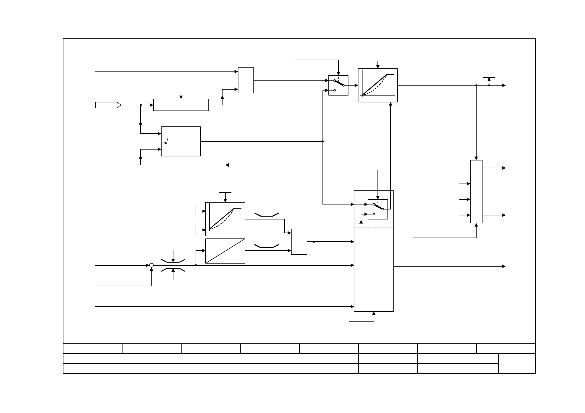
3 Function diagrams
3.13 Vector control
SINAMICS G120C
418 List Manual (LH13), 04/2014, A5E33840768B AA
Fig. 3-85 6721 – Id setpoint (PEM, p0300 = 2)
- 6721 -
Function diagram
87654321
fp_6721_97_05.vsd
Vector control
SINAMICS G120C
07.04.2014 V4.7
Id setpoint (PEM, p0300 = 2)
1
0
[6060.7]
[6714]
MAX
MIN
22
Iq
Iabs
[6724]
M
Iq
[6640.5]
[6710.2]
[6799.7]
[6714]
Ld
Lq
kt
Rel
[6731.2]
[6040.4]
[6731.3]
[6060.4]
r1538
r1539
n-Ctrl = 1
Iabs
pre
M
1
0
Iabs
(r1407.2)
0 = M-Ctrl
1 = n-Ctrl
I
d
Id_inject
Iq
M
From Id_field weakening
r1515 M_suppl total
M_acceleration
Motor model deviation component 1
Load angle correction
from the model
control
M adaptation
To current controller
kT adaptation corrective value
from model control
Torque setting value, speed controller
Id_set
Mot t_excitation
0.000 ... 20.000 [s]
p0346 [D] (0.000)
Id_setp total [Arms]
r1624
PEM: Permanent-magnet synchronous motor
Load angle for
synchronous motors
90°
r0077
Iq_set [Arms]
40 [ms]
Motor reluctance torque
constant
Motor leakage inductance,
total
Motor stator inductance,
d axis
M_set static
-200.0 ... 200.0 [%]
p1610 [D] (50.0)
M_suppl_accel
0.0 ... 200.0 [%]
p1611 [D] (30.0)
0.9 x
r0067
r0067
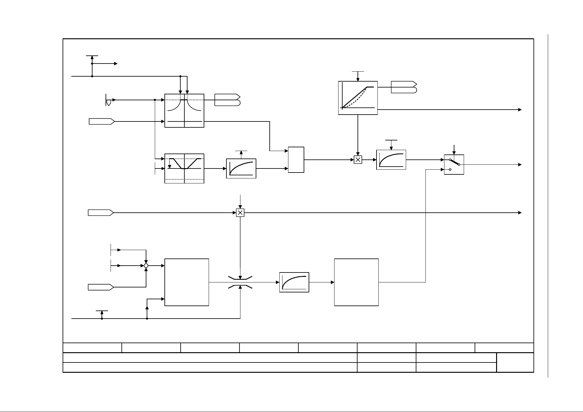
SINAMICS G120C
List Manual (LH13), 04/2014, A5E33840768B AA
419
3 Function diagrams
3.13 Vector control
Fig. 3-86 6722 – Field weakening characteristic, Id setpoint (ASM, p0300 = 1)
- 6722 -
Function diagram
87654321
fp_6722_97_05.vsd
Vector control
SINAMICS G120C
07.04.2014 V4.7
Field weakening characteristic, Id setpoint (ASM, p0300 = 1)
–
0,9
1
0
MIN
<0,3 s
f
y
[6060.5]
[6723.1]
[6640.3]
[6723.1]
[6730.1]
[6640.1]
+
+
[2526.2]
[2526.2]
U_output max [Vrms]
r0071
Flex setp
50.0 ... 200.0 [%]
p1570 [D] (100.0)
ZSW cl-loop ctrl
r0056
r0056
.8
Mot T_rotor/T_Dd [ms]
r0384 [D]
r1508
M_set bef. M_suppl [Nm]
Mot I_mag_rtd act [Arms]
r0331 [D]
ZSW cl-loop ctrl
r0056
r0056
Flux setp T_smth
4 ... 5000 [ms]
p1582 [D] (15)
Field weakening
characteristic
Efficiency optimization
Id_set calculation
Flux setpoint
calculation
Magnetization control
Id current limit
ASM: Induction motor
Mot t_excitation
0.000 ... 20.000 [s]
p0346 [D] (0.000)
r0067
I_outp max [Arms]
r0063
n_act [rpm]
[0]
Quick magnetizing active
[6723.8]
Value range and/or factory setting depend on Power Module.<1>
<1>
40 ms
Flux setpoint smoothed
from motor model
Efficiency opt.
0 ... 100 [%]
p1580 [D] (0)
M_set static
-200.0 ... 200.0 [%]
p1610 [D] (50.0)
M_suppl_accel
0.0 ... 200.0 [%]
p1611 [D] (30.0)
.4
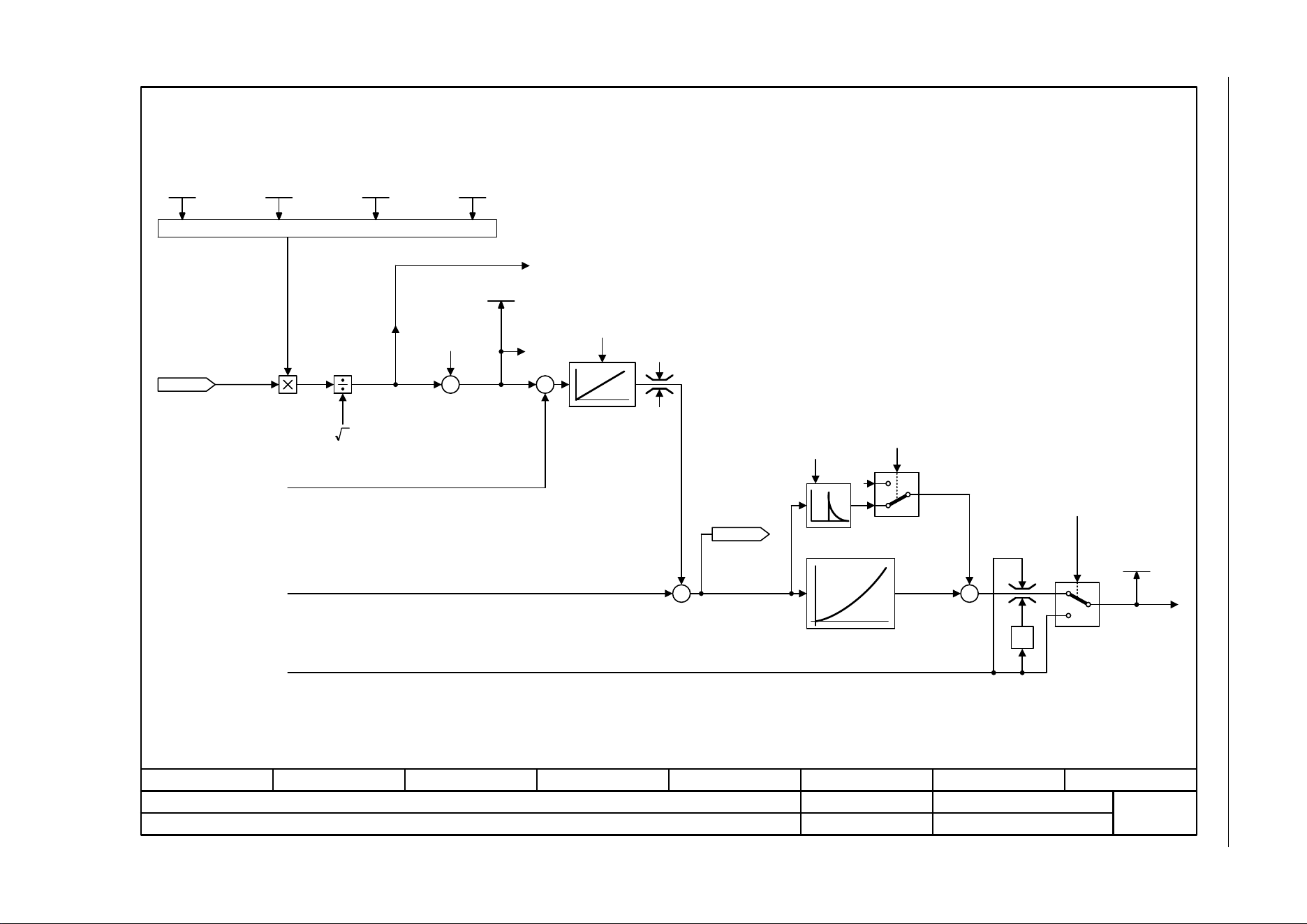
3 Function diagrams
3.13 Vector control
SINAMICS G120C
420 List Manual (LH13), 04/2014, A5E33840768B AA
Fig. 3-87 6723 – Field weakening controller, flux controller (ASM, p0300 = 1)
- 6723 -
Function diagram
87654321
fp_6723_97_05.vsd
Vector control
SINAMICS G120C
07.04.2014 V4.7
Field weakening controller, flux controller (ASM, p0300 = 1)
2
-1
1
0
0
U_max 1
[6722.8]
+
[6714.8]
[6730.1]
[6714.8]
–
[6714.1]
0
-200 %
[6722.8]
[6640.1]
Calculation, max. modulation depth
U_set 1
Id current limit
Saturation characteristic
p0362 ... p0369
ASM: Induction motor
r0070
Vdc act val [V]
U_output max [Vrms]
r0071
r1598
Flux setp total [%]
Drv filt type mot
0 ... 4 [kW]
p0230 (0)
Pulse freq setp
2.000 ... 16.000 [kHz]
p1800 [D] (4.000)
1
0
[6722.8]
[6714.1]
Quick magnetizing active
Flux setpoint smoothed
Id_setp total [Arms]
r1624
Voltage reserve
dynamic
[10.0 V]
Field weakening
controller integral-
action time
[300 ms]
Flux build-up control
active
Flux setpoint
differentiation
active
Modulator mode
0 ... 10
p1802 [D] (0)
Modulat depth max
20.0 ... 150.0 [%]
p1803 [D] (106.0)
–
+
+
+
+
+
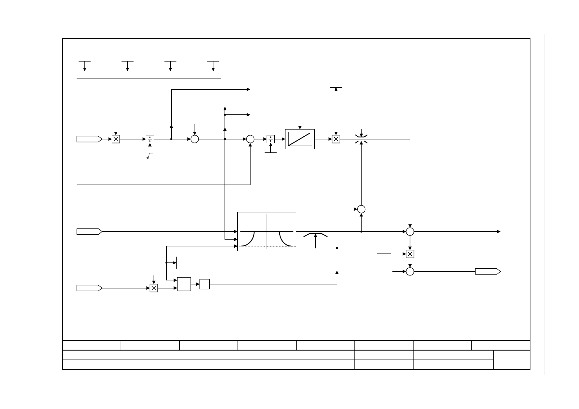
SINAMICS G120C
List Manual (LH13), 04/2014, A5E33840768B AA
421
3 Function diagrams
3.13 Vector control
Fig. 3-88 6724 – Field weakening controller (PEM, p0300 = 2)
- 6724 -
Function diagram
87654321
fp_6724_97_05.vsd
Vector control
SINAMICS G120C
07.04.2014 V4.7
Field weakening controller (PEM, p0300 = 2)
2
U_max 1
[6640.3]
+
[6640.1]
[6714.8]
[6731.1]
[6714.8]
–
[6731.1]
0
0.9
Min -1
-n
F
n
F
[6721.1]
100 %
nom
d
L
ψ
U_set 1
Id_field weaken. Ctrl
PEM: Permanent-magnet synchronous motor
r0070
Vdc act val [V]
U_output max [Vrms]
r0071
Mot U_rated
0 ... 20000 [Vrms]
p0304 [D] (0)
Mot I_mag_rtd act [Arms]
r0331 [D]
r1598
Flux setp total [%]
Drv filt type mot
0 ... 4 [kW]
p0230 (0)
Pulse freq setp
2.000 ... 16.000 [kHz]
p1800 [D] (4.000)
Calculation, max. modulation depth
Mot I_mag_rtd act [Arms]
r0331 [D]
r0067
I_outp max [Arms]
r0063
n_act [rpm]
[0]
Voltage reserve
dynamic
[10.0 V]
Field weakening
controller integral-
action time
[300 ms]
Modulator mode
0 ... 10
p1802 [D] (0)
Modulat depth max
20.0 ... 150.0 [%]
p1803 [D] (106.0)
+
–
+
+
+
–
+
+
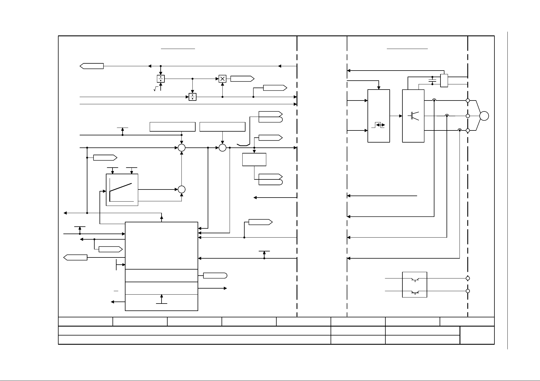
3 Function diagrams
3.13 Vector control
SINAMICS G120C
422 List Manual (LH13), 04/2014, A5E33840768B AA
Fig. 3-89 6730 – Interface to the Power Module (ASM, p0300 = 1)
- 6730 -
Function diagram
87654321
fp_6730_97_05.vsd
Vector control
SINAMICS G120C
07.04.2014 V4.7
Interface to the Power Module (ASM, p0300 = 1)
[8012.3]
[6723.1]
[6799.1]
PWM
M
~
U
V
W
+ BRP
-BRN
P24
M
p1755
Kp Tn
p1764
2
[6300.1]
[6640.1]
Iq
M
[6722.7]
r1408.12
[6310.5]
[6640.5]
[6710.2]
+
[6300.8]
[6714.8]
[6799.1]
[6799.1]
[6799.1]
[2526.2]
Pre-control speed
n_act
Adaptation controller
Motor model
Stall monitoring
Model control
Vibration damping
Sign
+ or -
I_max PM
Brake control
I_max PM
Pulse enable HW
DC link voltage
Power ModuleControl Unit
U_set
U_angle
r0070
Vdc act val [V]
r0072
U_output [Vrms]
r0074
Modulat_depth [%]
f_Slip
r0065
ZSW cl-loop ctrl
r0056
r0056
.11
r0066
f_outp [Hz]
ZSW cl-loop ctrl
r0056
r0056
.07
R_stator act
r0395
r0087
Cos phi act
r0084
Flux act val [%]
[6030.8]
[6310.1] [6799.1]
Current model
Outp_ph_seq rev
p1820
p1767
U_phase act val [V]
r0089[0..2]
r0069[0..6]
I_phase act value [A]
r0063[0..2]
n_act [rpm]
p1745
Internal interface Power Module - Control Unit
+
+
+
+
+
+
ASM: Induction motor
[6714.1]
[2701.8]
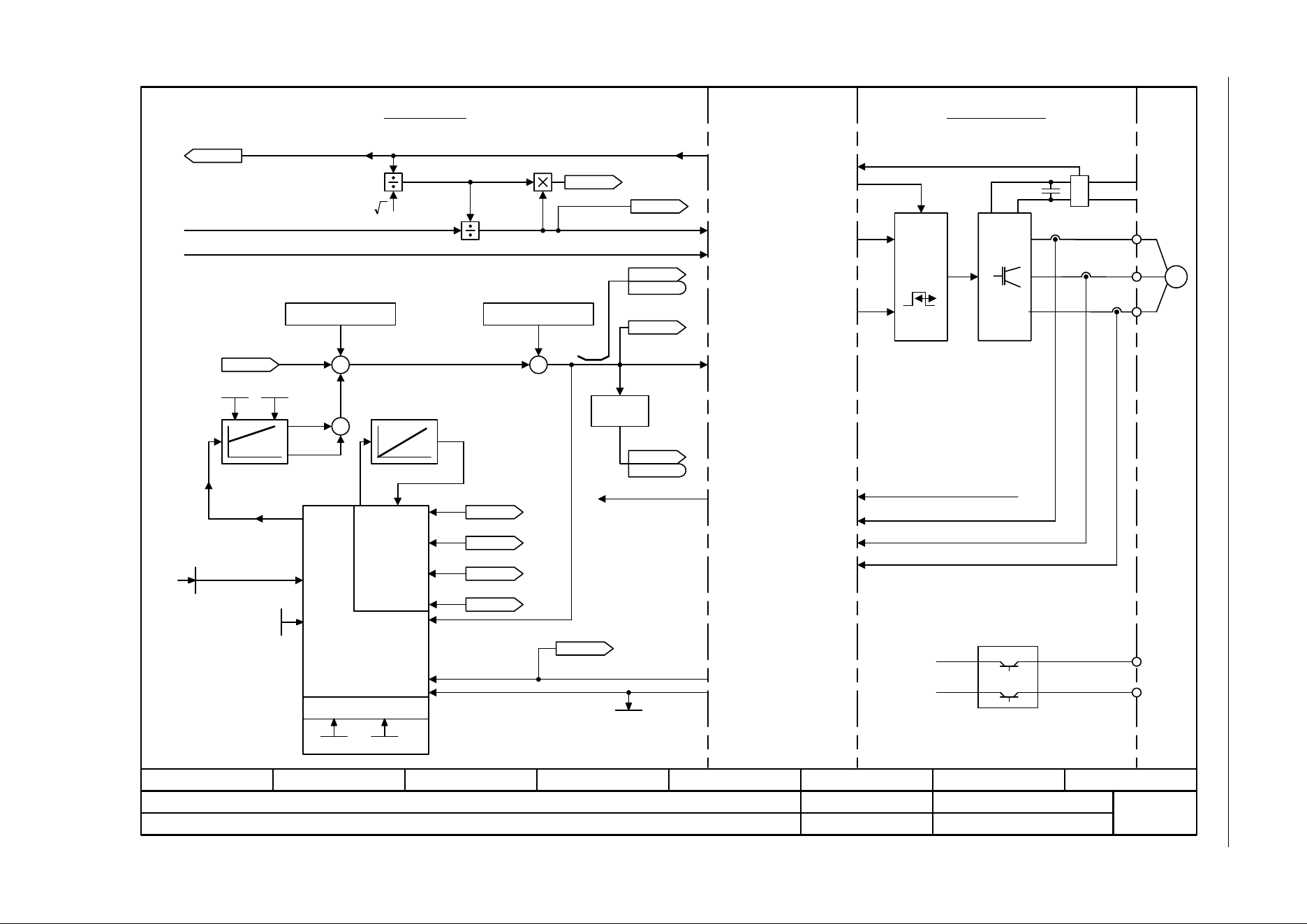
SINAMICS G120C
List Manual (LH13), 04/2014, A5E33840768B AA
423
3 Function diagrams
3.13 Vector control
Fig. 3-90 6731 – Interface to the Power Module (PEM, p0300 = 2)
- 6731 -
Function diagram
87654321
fp_6731_97_05.vsd
Vector control
SINAMICS G120C
07.04.2014 V4.7
Interface to the Power Module (PEM, p0300 = 2)
PWM
M
~
U
V
W
+ BRP
-BRN
P24
M
2
I_max Power Module
[6640.1]
[6310.1]
[6799.1]
[6714.8]
[6714.8]
[6799.1]
[6799.1]
[6724.1]
[6799.1]
p1764 p1767
+
[2526.2]
Pre-control speed
Brake control
I_max PM
Pulse enable HW
DC link voltage
Power ModuleControl Unit
U_set
U_angle
Motor model
Model control
kT estimator
p0316
p0357
p1780.3
PEM: Permanent-magnet synchronous motor
r0070
Vdc act val [V]
r0072
U_output [Vrms]
r0074
Modulat_depth [%]
ZSW cl-loop ctrl
r0056
r0056
.11
r0066
f_outp [Hz]
ZSW cl-loop ctrl
r0056
r0056
U_phase act val
r0089
r1733
Quad U set [Vrms]
r0077
Iq_set [Arms]
r0076
Id_act [Arms]
R_stator act [Ohm]
r0395 [D]
Vibration damping
Sign
+ or -
Current model
[6030.8]
p1755
Outp_ph_seq rev
p1820
r0063
n_act [rpm]
[0]
r1732
Direct U set [Vrms]
[0]
r0069[0..6]
I_phase act value [A]
Internal interface Power Module - Control Unit
+
+
+
.7
[6714.1]
[6714.6]
[6714.6]
p1756
[2701.8]
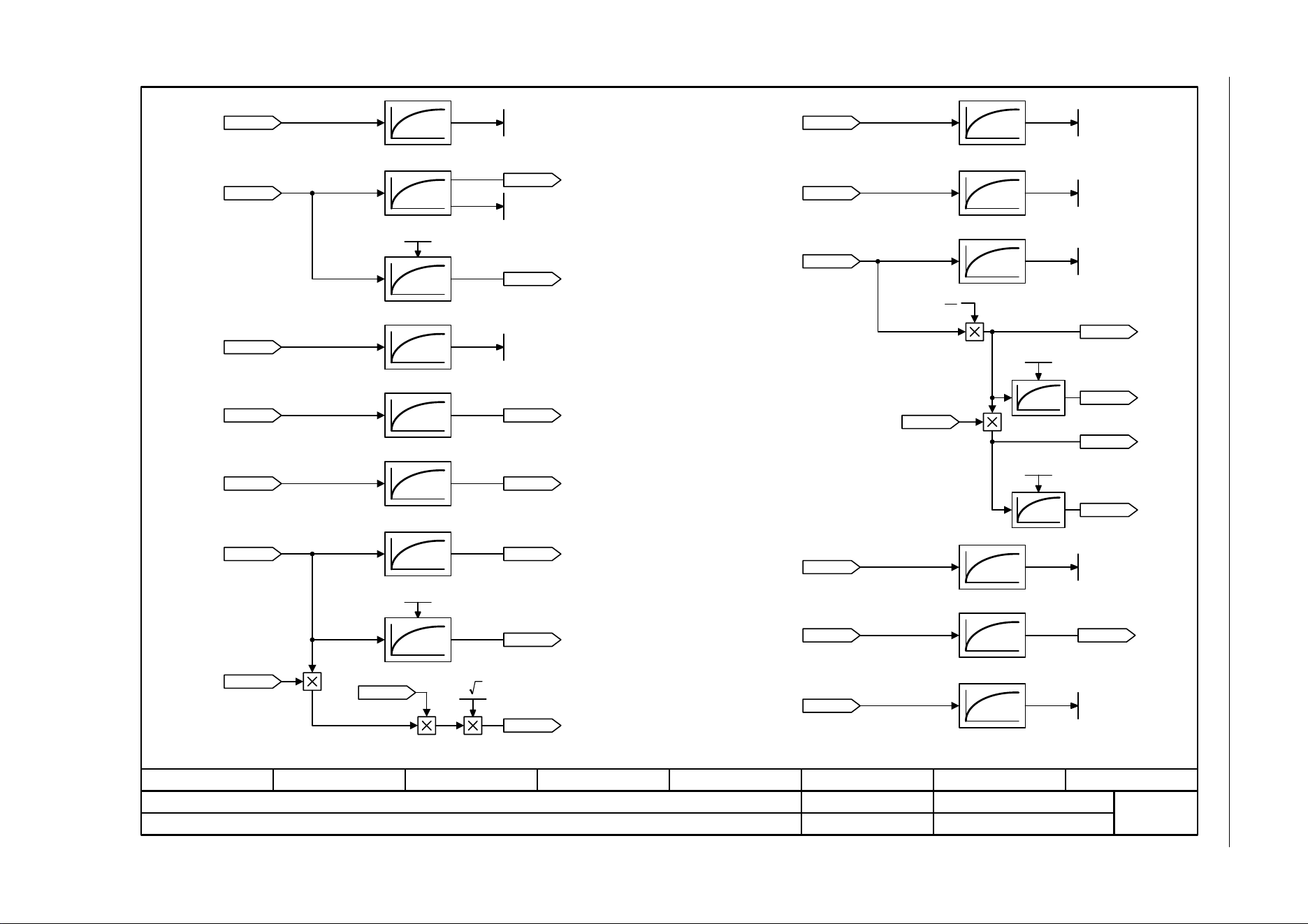
3 Function diagrams
3.13 Vector control
SINAMICS G120C
424 List Manual (LH13), 04/2014, A5E33840768B AA
Fig. 3-91 6799 – Display signals
- 6799 -
Function diagram
87654321
fp_6799_97_66.vsd
Vector control
SINAMICS G120C
07.04.2014 V4.7
Display signals
100 ms
[4715.6]
[6714.8]
[6714.8]
[6799.8]
300 ms100 ms
100 ms
100 ms
100 ms
300 ms
100 ms
300 ms
100 ms
[6730.4]
[6731.4]
[6730.4]
[6731.4]
[6730.1]
[6731.1]
[6730.4]
[6731.4]
r0060
n_set before filt. [rpm]
r0066
f_outp [Hz]
r0072
U_output [Vrms]
r0070
Vdc act val [V]
r0074
Modulat_depth [%]
r0076
Id_act [Arms]
r0078
Iq_act [Arms]
n_set smth [rpm]
r0020
r0021
n_act smooth [rpm]
f_outp smooth [Hz]
r0024
r0025
U_outp smooth [Vrms]
r0026
Vdc smooth [V]
r0027
I_act abs val smth [Arms]
Mod_depth smth [%]
r0028
Id_act smooth [Arms]
r0029
Iq_act smooth [Arms]
r0030
M_act smooth [Nm]
r0031
Disp_val T_smooth
p0045
r0063[1]
n_act [rpm]
300 ms
[6730.1] r0087
Cos phi act
Cos phi smooth
r0038
[6799.8]
100 ms
r0032
P_actv_act smth [kW]
r0063
n_act [rpm]
r0068
I_act abs val [Arms]
[0]
r0080
M_act [Nm]
r0082
P_act [kW]
Disp_val T_smooth
p0045
r0068
I_act abs val [Arms]
3
<1> [6730.4]
r0072
U_output [Vrms]
<1> [6730.1]
r0087
Cos phi act
r0082
P_act [kW]
Iq
M
<1> [6730.1]
<2> [6721.8]
r0080
M_act [Nm]
[0]
r0080
M_act [Nm]
[1]
Disp_val T_smooth
p0045
r0082
P_act [kW]
[0]
r0082
P_act [kW]
[1]
Disp_val T_smooth
p0045
r0063
n_act [rpm]
<1>
<2>
For induction motors
For synchronous motors
[6714.8]
[6799.6]
[6799.6]
[0]
[2]
[1]
[0]
[0]
[0]
[6030.2]
n_act rpm smooth [rpm]
r0022

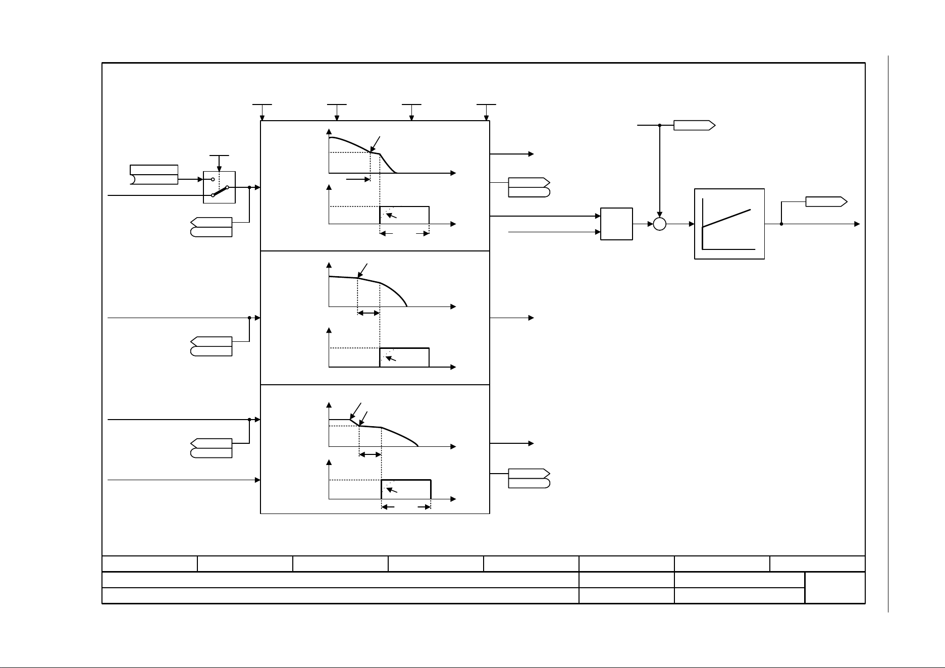
3 Function diagrams
3.14 Technology functions
SINAMICS G120C
426 List Manual (LH13), 04/2014, A5E33840768B AA
Fig. 3-92 7017 – DC brake (p0300 = 1)
- 7017 -
Function diagram
87654321
fp_7017_97_05.vsd
Technology functions
SINAMICS G120C
07.04.2014 V4.7
DC brake (p0300 = 1)
MIN
–
[6714]
Kp Tn
Current actual values
To control [6730]
To U/f characteristic
[6301]
r0072
U_output [Vrms]
r0068[0..1]
I_act abs val [Arms]
p0347
p1234
p1233
p1232
p0347
p1232
<1>
<2>
<3>
<1>
<2>
0
4
t
t
t
t
OFF
p1231 = 5 (OFF1/OFF3)
Pulse inhibit
Pulse inhibit
n_act
n_set
|I_set|
n_act
n_set
Braking response
|I_set|
|I_act|
The DC braking current is determined during automatic calculation (p0340 = 1).
The de-magnetization time is determined during automatic calculation (p0340 = 1, 3).
To pulse inhibit
To sequence control
From I²t control [8014]
|I_set|
(0)
DCBRK Akt
p1230 [C]
DCBRK config
0 ... 14
p1231 [D] (0)
DCBRK I_brake
0.00 ... 10000.00 [Arms]
p1232 [D] (0.00)
DCBRK time
0.0 ... 3600.0 [s]
p1233 [D] (1.0)
DCBRK n_start
0.00 ... 210000.00 [rpm]
p1234 [D] (210000.00)
DCBRK ZSW
r1239
r1239
.10
DCBRK ZSW
r1239
r1239
DCBRK ZSW
r1239
r1239
Mot t_de-excitat
0.000 ... 20.000 [s]
p0347 [D] (0.000)
14
To pulse inhibit
To sequence control
To pulse inhibit
To sequence
control
|I_act|
p1234
p1233
p1232
p0347
t
t
Pulse inhibitn_act
n_set
|I_set|
|I_act|
DC brake fault response
p1231 = 4 (control command)
DCBRK ZSW
r1239
r1239
DCBRK ZSW
r1239
r1239
DC braking when starting speed for DC braking (p1234) is fallen below.
<3>
.8

SINAMICS G120C
List Manual (LH13), 04/2014, A5E33840768B AA
427
3 Function diagrams
3.15 Technology controller
3.15 Technology controller
Function diagrams
7950 – Fixed value selection binary (p2216 = 2) 428
7951 – Fixed value selection direct (p2216 = 1) 429
7954 – Motorized potentiometer 430
7958 – Closed-loop control 431
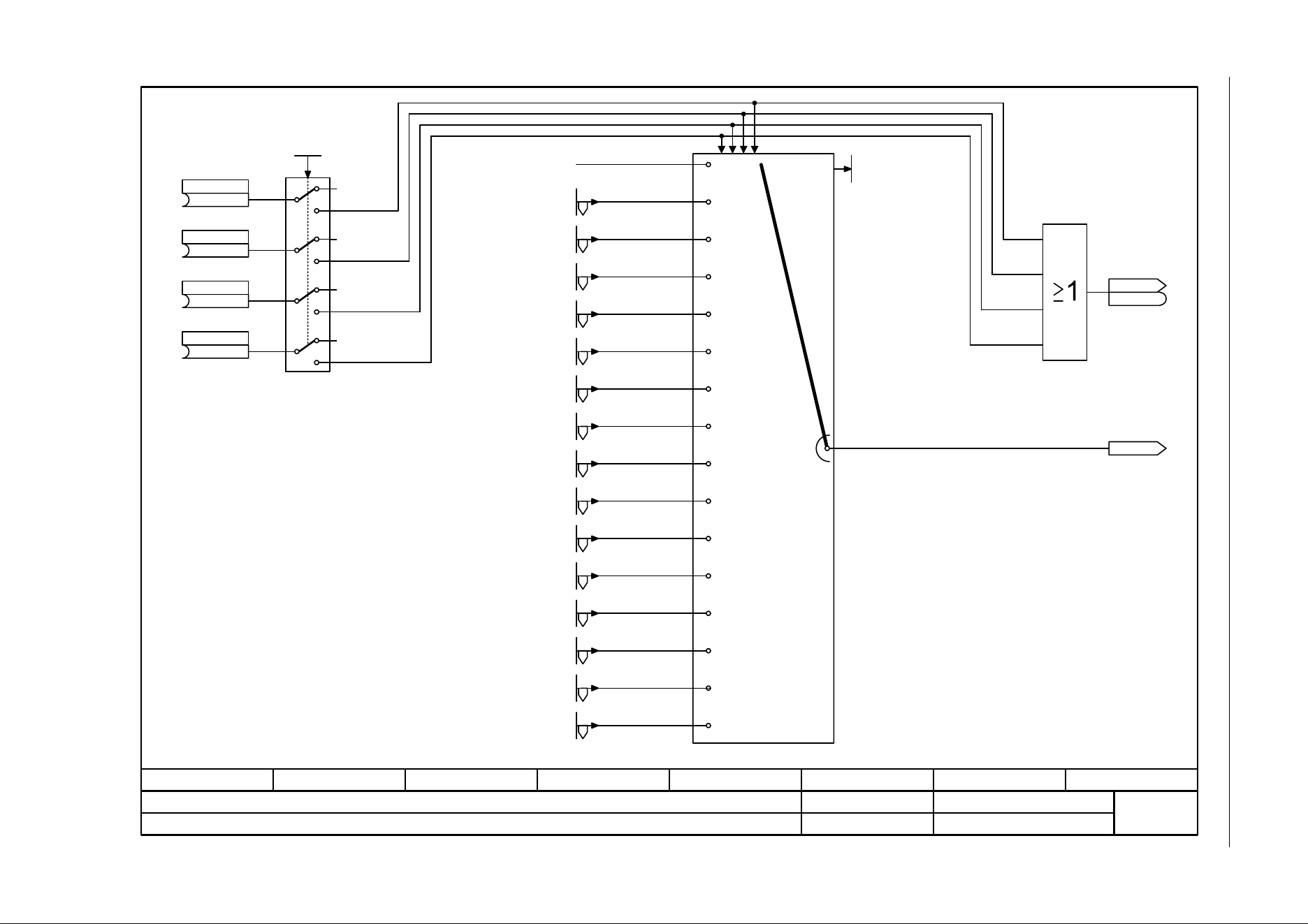
3 Function diagrams
3.15 Technology controller
SINAMICS G120C
428 List Manual (LH13), 04/2014, A5E33840768B AA
Fig. 3-93 7950 – Fixed value selection binary (p2216 = 2)
- 7950 -
Function diagram
87654321
fp_7950_97_05.vsd
Technology controller
SINAMICS G120C
07.04.2014 V4.7
Fixed value selection binary (p2216 = 2)
1 1 1 0
0 0 0 0
0.00 %
0 ... 152
0
2
3
Tec_ctrl No. act
r2229
r2224
Tec_ctr FixVal eff [%]
Tec_ctr FixVal ZSW
r2225
r2225
(0)
Tec_ctrl sel bit 0
p2220 [C]
(0)
Tec_ctrl sel bit 1
p2221 [C]
(0)
Tec_ctrl sel bit 2
p2222 [C]
(0)
Tec_ctrl sel bit 3
p2223 [C]
1
1
1
1
2
Tec_ctr FixVal sel
1 ... 2
p2216 [D] (1)
2
2
2
0 0 1 0
0 0 0 1
0 0 1 1
0 1 0 0
0 1 0 1
0 1 1 0
0 1 1 1
1 0 0 0
1 0 0 1
1 0 1 0
1 0 1 1
1 1 0 0
1 1 0 1
1 1 1 1
.0
Tec_ctrl fix val1 [%]
p2201 [D] (10.00)
Tec_ctr fix val 2 [%]
p2202 [D] (20.00)
Tec_ctr fix val 3 [%]
p2203 [D] (30.00)
Tec_ctr fix val 4 [%]
p2204 [D] (40.00)
Tec_ctr fix val 5 [%]
p2205 [D] (50.00)
Tec_ctr fix val 6 [%]
p2206 [D] (60.00)
Tec_ctr fix val 7 [%]
p2207 [D] (70.00)
Tec_ctr fix val 8 [%]
p2208 [D] (80.00)
Tec_ctr fix val 9 [%]
p2209 [D] (90.00)
Tec_ctr fix val 10 [%]
p2210 [D] (100.00)
Tec_ctr fix val 11 [%]
p2211 [D] (110.00)
Tec_ctr fix val 12 [%]
p2212 [D] (120.00)
Tec_ctr fix val 13 [%]
p2213 [D] (130.00)
Tec_ctr fix val 14 [%]
p2214 [D] (140.00)
Tec_ctr fix val 15 [%]
p2215 [D] (150.00)
[7951]
[7951]
[7951]
[7951]
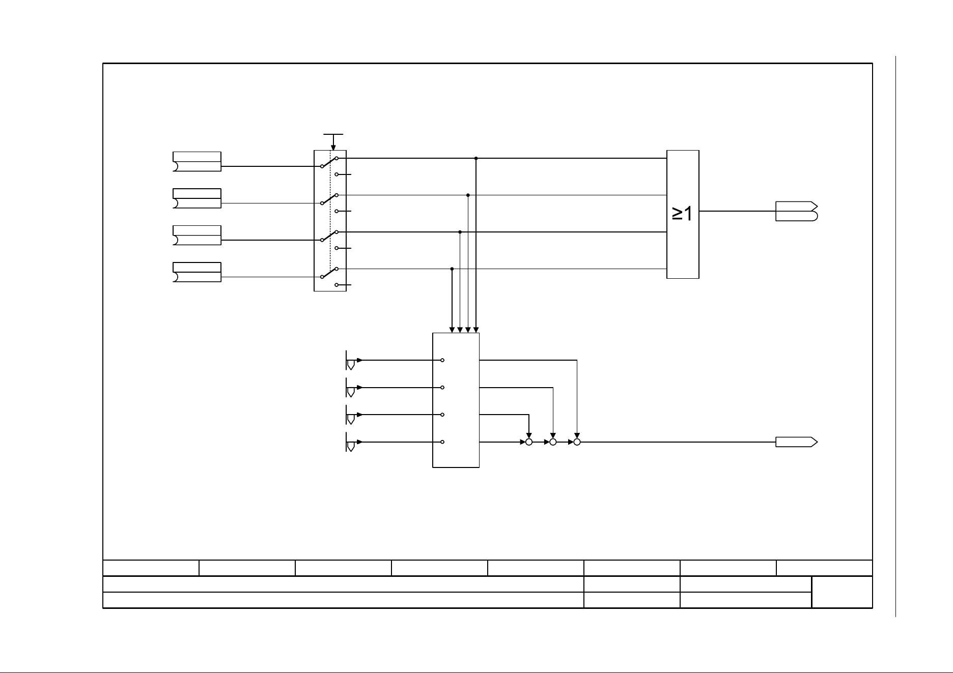
SINAMICS G120C
List Manual (LH13), 04/2014, A5E33840768B AA
429
3 Function diagrams
3.15 Technology controller
Fig. 3-94 7951 – Fixed value selection direct (p2216 = 1)
- 7951 -
Function diagram
87654321
fp_7951_97_05.vsd
Technology controller
SINAMICS G120C
07.04.2014 V4.7
Fixed value selection direct (p2216 = 1)
+
r2224
Tec_ctr FixVal eff [%]
Tec_ctr FixVal ZSW
r2225
r2225
(0)
Tec_ctrl sel bit 0
p2220 [C]
(0)
Tec_ctrl sel bit 1
p2221 [C]
(0)
Tec_ctrl sel bit 2
p2222 [C]
(0)
Tec_ctrl sel bit 3
p2223 [C]
1
1
1
1
Tec_ctr FixVal sel
1 ... 2
p2216 [D] (1)
2
2
2
2
1 0 0 0
0 1 0 0
0 0 1 0
0 0 0 1
+
+++
+
Tec_ctrl fix val1 [%]
p2201 [D] (10.00)
Tec_ctr fix val 2 [%]
p2202 [D] (20.00)
Tec_ctr fix val 3 [%]
p2203 [D] (30.00)
Tec_ctr fix val 4 [%]
p2204 [D] (40.00)
.0
[7950]
[7950]
[7950]
[7950]
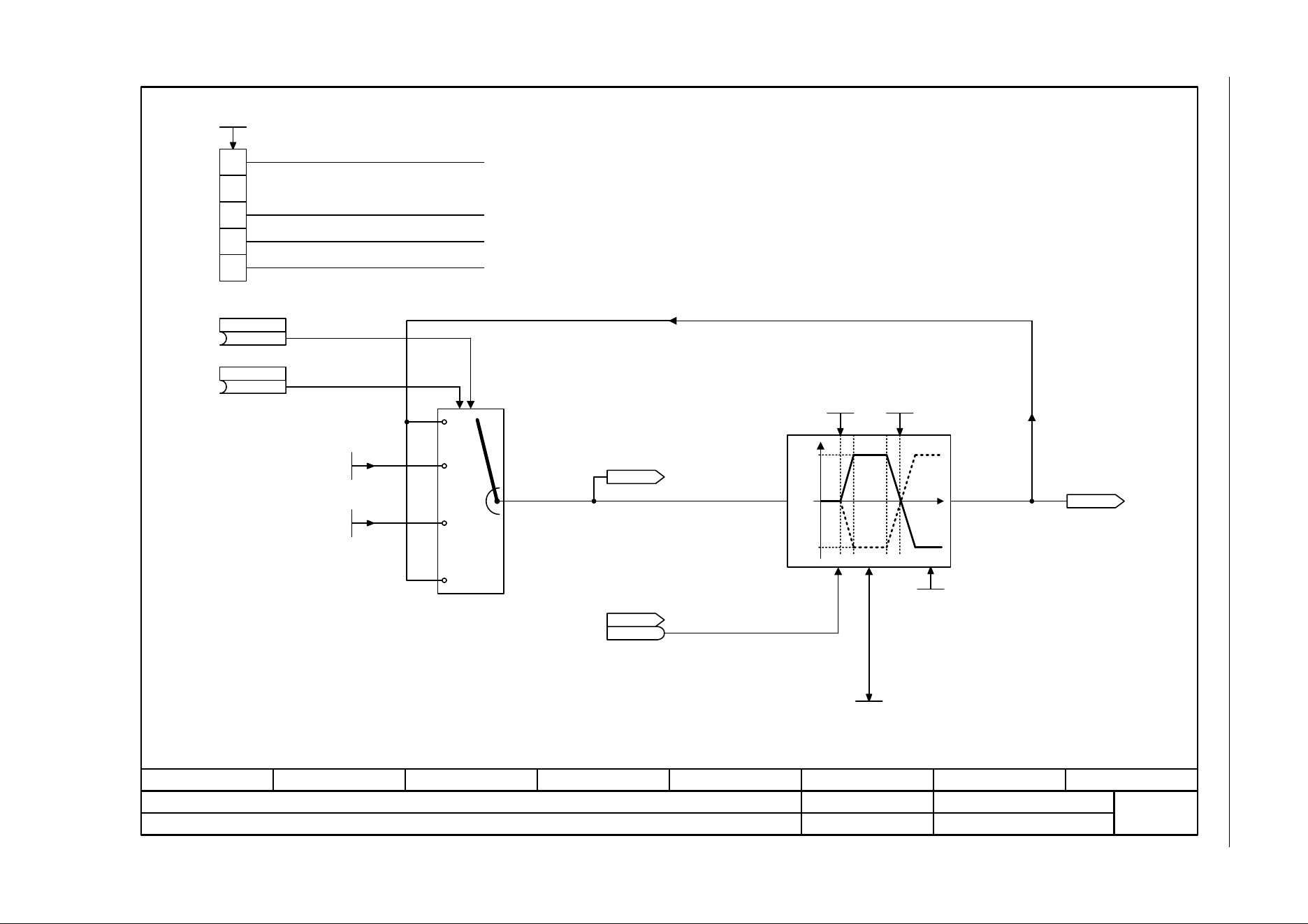
3 Function diagrams
3.15 Technology controller
SINAMICS G120C
430 List Manual (LH13), 04/2014, A5E33840768B AA
Fig. 3-95 7954 – Motorized potentiometer
- 7954 -
Function diagram
87654321
fp_7954_97_61.vsd
Technology controller
SINAMICS G120C
07.04.2014 V4.7
Motorized potentiometer
<1>
<2> <2>
0 0
0 1
1 0
1 1
y
p2237
-p2238
x
y = 0
0
1
2
3
Data save active
Initial rounding-off active
Non-volatile data save active
0 The setpoint for the motorized potentiometer is not saved and after ON is entered using p2240.
1 The setpoint for the motorized potentiometer is saved after OFF and after ON is entered using r2231.
0 Without initial rounding.
1 With initial rounding. The ramp-up/down time set is exceeded accordingly.
0 Non-volatile data save not activated
1 The setpoint for the motorized potentiometer is saved in a non-volatile fashion (for p2230.0 = 1)
Old value is kept
1 = OFF1, enable missing
For p2230.0 = 0, this setpoint is entered after ON.
If initial rounding-off is active (p2230.2 = 1), the selected ramp-up/down times are exceeded accordingly.
(0)
Tec_ctrl mop raise
p2235 [C]
(0)
Tec_ctrl mop lower
p2236 [C]
Tec_ctrl mop max
-200.00 ... 200.00 [%]
p2237 [D] (100.00)
Tec_ctrl mop min
-200.00 ... 200.00 [%]
p2238 [D] (-100.00)
r2245
Tec_ctr mop befRFG [%]
Tec_ctr mop t_r-up
0.0 ... 1000.0 [s]
p2247 [D] (10.0)
Tec_ctrMop t_rdown
0.0 ... 1000.0 [s]
p2248 [D] (10.0)
Tec_ctrl mop start
-200.00 ... 200.00 [%]
p2240 [D] (0.00)
Tec_ctrl mop mem [%]
r2231
Missing enable sig
r0046
r0046
r2250
Tec_ctr mop aftRFG [%]
Tec_ctr mop config
p2230 [D] (0000 0100 bin)
4
0
1
Ramp-function generator is always active
Ramp-up encoder inactive with pulse inhibit.
The ramp-up encoder is calculated independently of the pulse enable.
p2237
.0
yx
<1>
<2>
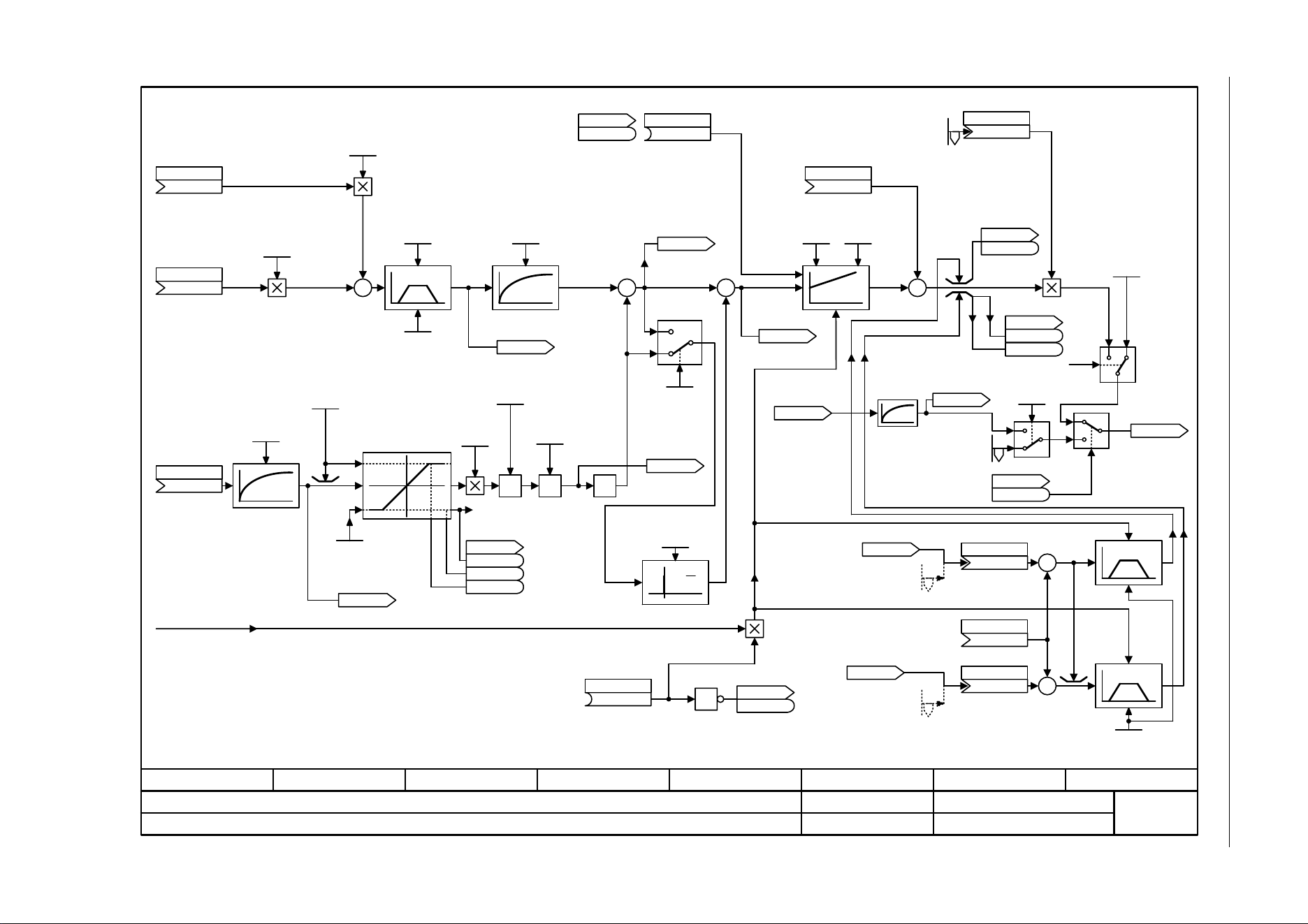
SINAMICS G120C
List Manual (LH13), 04/2014, A5E33840768B AA
431
3 Function diagrams
3.15 Technology controller
Fig. 3-96 7958 – Closed-loop control
- 7958 -
Function diagram
87654321
fp_7958_97_05.vsd
Technology controller
SINAMICS G120C
07.04.2014 V4.7
Closed-loop control
+
+
+
+
<1>
<1>
<1>
+
d
dt
Tec_reg Kp
0.000...1000.000
p2280 (1.000)
<1>
Tec_reg Tn
0.000...60.000 s
p2285 (0.000)
Tec_reg Vorsteuer
(0)
p2289[C]
1
+
p2263 = 1
p2263 = 0
x
y
F07426
-1
P, I and D components can be inhibited by entering a zero.
Tec_ctrl set1 scal
0.00 ... 100.00 [%]
p2255 (100.00)
Tec_ctrl setp 1
(0)
p2253 [C]
Tec_ctrl setp 2
(0)
p2254 [C]
Tec_ctrl set2 scal
0.00 ... 100.00 [%]
p2256 (100.00)
Tec_ctrl t_ramp-up
0.00 ... 650.00 [s]
p2257 (1.00)
Tec_ctrl t_ramp-dn
0.00 ... 650.00 [s]
p2258 (1.00)
Tec_ctrl set T
0.000 ... 60.000 [s]
p2261 (0.000)
r2260
Tec_ctr set aftRFG [%]
r2273
Tec_ctrl error [%]
r2273
Tec_ctrl error [%]
Tec_ctrl outp scal
(2295[0])
p2296 [C]
Tec_ctrMaxLimS_src
(1084[0])
p2297 [C]
Tec_ctrl min_l s_s
(1087[0])
p2298 [C]
Tec_ctr t_RU/RD
0.00 ... 100.00 [s]
p2293 (1.00)
Tec_ctrl status
r2349
r2349
(0)
Tec_ctrl enable
p2200 [C]
Tec_ctrl D comp T
0.000 ... 60.000 [s]
p2274 (0.000)
Tec_ctrl type
0 ... 1
p2263 (0)
Tec_ctrl l_lim act
-200.00 ... 200.00 [%]
p2268 (-100.00)
r2266
Tec_ctr act aftFlt [%]
Tech_ctrl gain act
0.00 ... 500.00 [%]
p2269 (100.00)
Tec_ctrl act T
0.000 ... 60.000 [s]
p2265 (0.000)
Tec_ctr ActVal fct
0 ... 3
p2270 (0)
Tec_ctrl outp scal
-100.00 ... 100.00 [%]
p2295 (100.00)
<4>
Tec_ctrl status
r2349
r2349
Tec_ctrl status
r2349
r2349
r0052.2 [2510.6]
Tec_ctr start val
0.00 ... 200.00 [%]
p2302 (0.00)
ZSW cl-loop ctrl
r0056
r0056
<3>
<2>
The start value p2302 is only used in mode p2251 = 0 (Technology controller as
speed main setpoint).
After enable of technology controller the start value is present as long as the RFG
output reaches this value.
<3>
I component stop, only when r2273 and r2294 in same direction.
<4> By p2251 = 1: p2299 = 0 (default), recommendation: p2299 connected to r1150.
Tec_ctrl u_lim act
-200.00 ... 200.00 [%]
p2267 (100.00)
Tech_ctrl lim offs
(0)
p2299 [C]
(56.13)
Tec_ctr integ hold
p2286 [C]
Tech_ctrl act inv
0 ... 1
p2271 (0)
Tec_ctrl status
r2349
r2349
.12
r2349.8
r2349.9
<5> r2349.12 = 1, if p2345 > 0 and actual value limited and start value p2302 not active.
Tec_ctrl act val
(0)
p2264 [C]
1
0
r2349.1
0
1
Tec_ctrl status
r2349
r2349
Tec_ctr fix val 15
-200.00 ... 200.00 [%]
p2215 [D] (150.00)
10 s
1
2
<2>
Tech_ctrl flt resp
0 ... 2
p2345 (0)
<5>
<5>
r1150
RFG n_set at
outp [rpm]
r2272
Tech_ctrl act
scal [%]
r2294
Tec_ctrl
outp_sig [%]
Tec_ctrl max_lim
-200.00 ... 200.00 [%]
p2291 (100.00)
r1084
n_limit pos eff [rpm]
Tec_ctrl min_lim
-200.00 ... 200.00 [%]
p2292 (0.00)
r1087
n_limit neg eff [rpm]
<6>
Signal = 0 --> factor = 0, when setpoint from external OP or operating tool
<6>
r2344
Tec_ctrl
n_setp_sm
[%]
<7>
p2251 = 0: I component is stopped, when r2294 is below the minimum speed or within a suppression bandwidth.
<7>
.13
.0
+
+
.11
.10
.12
–
–
[3030.4]

3 Function diagrams
3.16 Signals and monitoring functions
SINAMICS G120C
432 List Manual (LH13), 04/2014, A5E33840768B AA
3.16 Signals and monitoring functions
Function diagrams
8005 – Overview 433
8010 – Speed signals 1 434
8011 – Speed signals 2 435
8012 – Torque signals, motor blocked/stalled 436
8014 – Thermal monitoring, power unit 437
8016 – Thermal monitoring, motor 438
8017 – Thermal motor models 439
8020 – Monitoring functions 1 440
8021 – Monitoring functions 2 441
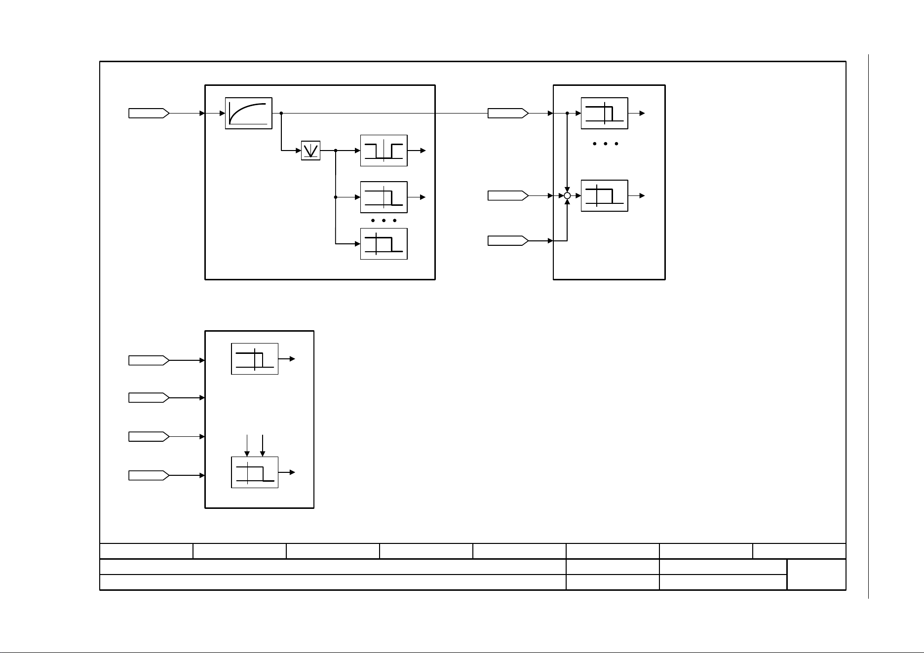
SINAMICS G120C
List Manual (LH13), 04/2014, A5E33840768B AA
433
3 Function diagrams
3.16 Signals and monitoring functions
Fig. 3-97 8005 – Overview
- 8005 -
Function diagram
87654321
fp_8005_97_05.vsd
Signals and monitoring functions
SINAMICS G120C
07.04.2014 V4.7
Overview
[3080]
[6010]
[6640]
[6640]
[8010]
[6060]
n_max
[8010] Speed messages 1
[8012] Torque messages
Motor locked
Limit value monitor
r2169
n_act smth message [rpm]
r1539
M_max lower eff [Nm]
r1538
M_max upper eff [Nm]
r0079
M_set [Nm]
r0063
n_act [rpm]
[0]
[8012]
[8011] Speed messages 2
r2169
n_act smth message [rpm]
[0]
[6031]
r1438
n_ctrl n_set [rpm]
r1170
n_ctrl setp sum
[rpm]

3 Function diagrams
3.16 Signals and monitoring functions
SINAMICS G120C
434 List Manual (LH13), 04/2014, A5E33840768B AA
Fig. 3-98 8010 – Speed signals 1
- 8010 -
Function diagram
87654321
fp_8010_97_05.vsd
Signals and monitoring functions
SINAMICS G120C
07.04.2014 V4.7
Speed signals 1
[8011.2]
[8012.5]
[6730.1]
[3050.8]
[2534.3]
<1>
n
n
0
From setpoint limiting
F07901 "motor overspeed"
Smoothing
Calculated.
r0063
n_act [rpm]
r0063
n_act [rpm]
r2169
n_act smth message [rpm]
ZSW monitor 1
r2197
r2197
.6
ZSW monitor 3
r2199
r2199
.1
r1084
n_limit pos eff [rpm]
r1087
n_limit neg eff [rpm]
[0]
[1]
[6799.4]
f or n comparison value
reached or exceeded
|n_act| > n_max
[2537.3]
<1>
0.00 [1/min]
n_act_filt T
0 ... 1000000 [ms]
p2153 [D] (0)
0
1
n_thresh val 1
0.00 ... 210000.00 [rpm]
p2141 [D] (5.00)
T0
t_on cmpr val rchd
0.0 ... 10000.0 [ms]
p2156 [D] (0.0)
p0311 • 0.5%

SINAMICS G120C
List Manual (LH13), 04/2014, A5E33840768B AA
435
3 Function diagrams
3.16 Signals and monitoring functions
Fig. 3-99 8011 – Speed signals 2
- 8011 -
Function diagram
87654321
fp_8011_97_05.vsd
Signals and monitoring functions
SINAMICS G120C
07.04.2014 V4.7
Speed signals 2
[8010.2]
<1>
Calculated.
Evaluation only for: Pulse
enable and operating enable
(r0899.2)
or OFF1
or OFF3
or rotating measurement.
r2169
n_act smth message [rpm]
ZSW monitor 2
r2198
r2198
ZSW monitor 1
r2197
r2197
ZSW monitor 1
r2197
r2197
.3
[2534.3]
n_act >= 0
n_set > 0
Speed setp - act val deviation in
tolerance t_off
[2536.3]
0
1
[2534.3]
<1>
[3070.8]
0
1
+
–
0T
1
T0
ZSW monitor 3
r2199
r2199
[2537.3]
Speed setp - act val deviation in
tolerance t_on
Priority
1 RESET
2 SET
[2537.3]
SET
(Q=1)
RESET
(Q=0)
Q
Q
ZSW monitor 3
r2199
r2199
1 = RESET
Ramp-up/ramp-down completed
<1>
<2>
<2>
0
r1170
n_ctrl setp sum [rpm]
2.00 [1/min]
Hysteresis speed 3
2.00 [1/min]
Hysteresis speed 3
200 [ms]
200 [ms]
Ramp-function generator active
0
.5
.7
.4
.5
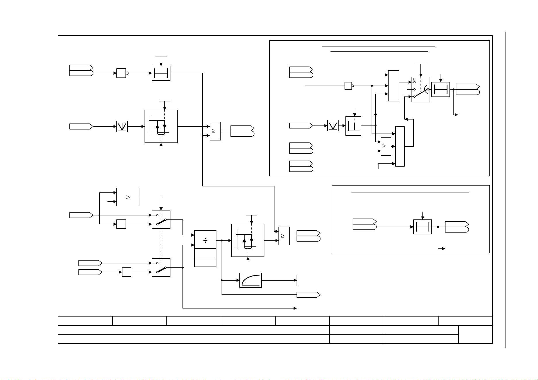
3 Function diagrams
3.16 Signals and monitoring functions
SINAMICS G120C
436 List Manual (LH13), 04/2014, A5E33840768B AA
Fig. 3-100 8012 – Torque signals, motor blocked/stalled
ZSW n_ctrl
r1407
r1407
- 8012 -
Function diagram
87654321
fp_8012_97_05.vsd
Signals and monitoring functions
SINAMICS G120C
07.04.2014 V4.7
Torque signals, motor blocked/stalled
[6640.8]
0
1
x
1
x
2
y
[%]
[Nm]
0
1
2
1
x
% 100x •
[Nm]
[3001.8]
100 ms
T0
F07902
[2536.3]
[6730.3]
T0
[8010.2]
F07900
[2522.7]
[2536.3]
[6060.8]
x
1
x
2
y
&
&
[2526.6]
x1 > x2 = y = 1
(positive torque requested)
Requested
torque
Actual torque limit
n_act smooth
signal < 120 [1/min]
Stall detection or stall monitoring (not for U/f control)
r0079
M_set [Nm]
r1538
M_max upper eff [Nm]
r1539
M_max lower eff [Nm]
M_util smooth [%]
r0033
r0081
M_Utilization [%]
.7
r2169
n_act smth message [rpm]
ZSW cl-loop ctrl
r0056
r0056
Op/cl-lp ctrl_mode
p1300
ZSW monitor 2
r2198
r2198
.6
ZSW I_ctrl
r1408
r1408
.12
ZSW monitor 2
r2198
r2198
.7
ZSW cl-loop ctrl
r0056
r0056
1
0..4,7
20
5,6,
19
0
-1
0
-1
1
3.000 [s]
0
120.00 [1/min]
0.010 [s]
<1>
Calculated.
<1>
<1>
<1>
Motor locked detection or motor locked monitoring
function (not for closed-loop torque control)
.12
.13
0
1
0
1
1
0T
[2537.7]
1
1
Ramp-function generator operating
ZSW monitor 3
r2199
r2199
M_util t_off
0.0 ... 1000.0 [ms]
p2195 [D] (800.0)
r0079
M_set [Nm]
M_thresh val 1
0.00 ... 20000000.00 [Nm]
p2174 [D] (5.13)
ZSW monitor 2
r2198
r2198
M_thresh val 2
0.00 ... 100.00 [%]
p2194 [D] (90.00)
ZSW monitor 3
r2199
r2199
.5
.10
.11
[2537.3]
[2536.3]
[6060.8]
1 = Motor stalled
1 = Motor blocked
2 % of p2174
2 % of p2194
[6640.8]
[2526.6]
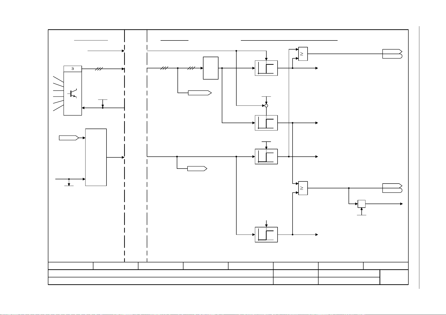
SINAMICS G120C
List Manual (LH13), 04/2014, A5E33840768B AA
437
3 Function diagrams
3.16 Signals and monitoring functions
Fig. 3-101 8014 – Thermal monitoring, power unit
- 8014 -
Function diagram
87654321
fp_8014_97_05.vsd
Signals and monitoring functions
SINAMICS G120C
07.04.2014 V4.7
Thermal monitoring, power module
Control Unit
Max
0
1
0
1
5 °C
+
-
0
1
[2548.2]
0
1
100 %
1
1
[2548.2]
[6714.8]
Power module
T_max heatsink
Temperature
measurement
i²t model
power
module
Maximum power module temperature
Thermal monitoring for the power module
1 = Fault thermal overload in power module
Faults "Power unit overtemperature"
F30004 Inverter heatsink
F30024 Thermal model
F30025 Chip
F30035 Air intake
Alarms "power unit overtemperature"
A05000 Inverter heatsink
A05001 Chip
A05002 Air intake
A05006 Chip to heatsink
F30005 "Power module overload"
1 = Alarm, thermal overload, power module
Overload response
A07805 "Power module overload"
Pulse freq setp
2.000 ... 16.000 [kHz]
p1800 [D] (4.000)
ZSW fault/alarm 2
r2135
r2135
.13
ZSW fault/alarm 2
r2135
r2135
PU overld response
0 ... 13
p0290 (2)
r0036
PU overload I2t [%]
r0068
I_act abs val [Arms]
[0]
PU PI_rated [Arms]
r0207[0..4]
r0037 [0..19]
PU temperatures [°C]
95.0 [%]
Alarm with I2t overload
Internal interface Power Module - Control Unit
.15
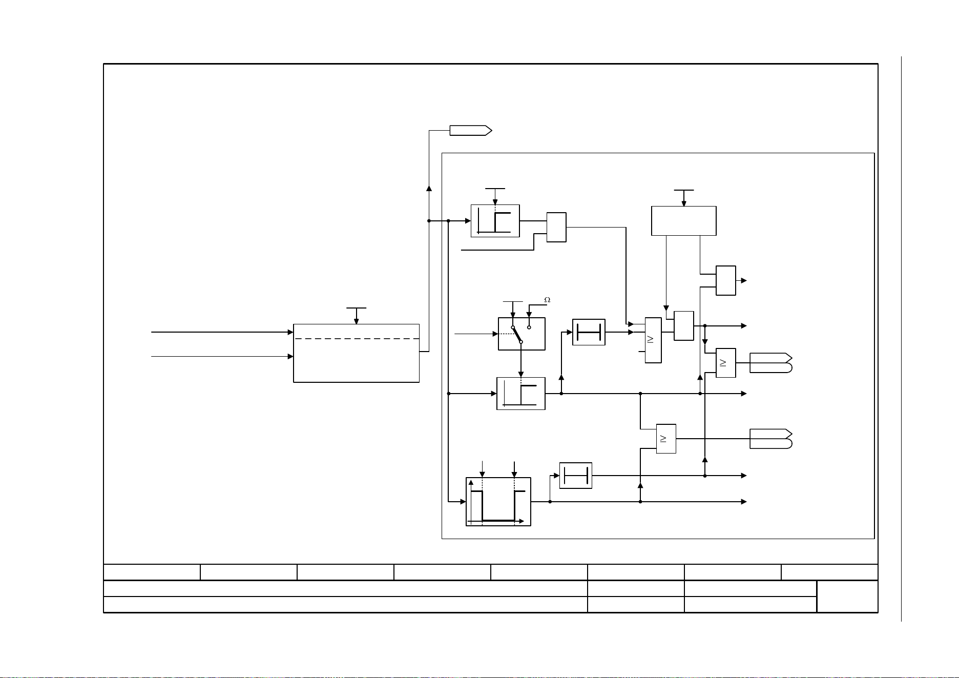
3 Function diagrams
3.16 Signals and monitoring functions
SINAMICS G120C
438 List Manual (LH13), 04/2014, A5E33840768B AA
Fig. 3-102 8016 – Thermal monitoring, motor
- 8016 -
Function diagram
87654321
fp_8016_97_05.vsd
Signals and monitoring functions
SINAMICS G120C
07.04.2014 V4.7
Thermal monitoring, motor
T0
&
&
[6300.1], [6640.2]
p0610 = 1
-140 °C 250 °C
0
1
&
1
1
T0
0
1
<4>
1650
For KTY and "No sensor", temperature as defined in the model.
The relevant rated response temperature in °C depends on the temperature sensor
chosen by the motor manufacturer.
0 = No sensor
PTC alarm and time
KTY84
Bimetal NC contact alarm with
time step
KTY sensor type
(threshold not applicable for PTC)
Sensor type
Fault response
Suppress fault
with p0610 = 0
F07011
"Motor overtemperature"
A07910
"Motor overtemperature"
A07016
"Motor temperature
sensor fault, fault"
A07015
"Motor temperature
sensor fault alarm"
r0035
Mot temp [°C]
Mot_temp_sens type
0 ... 4
p0601 [D] (0)
1
Mod 2/KTY A thresh
p0604
Mod 1/2 threshold
p0605
Mot temp response
p0610
1 = Alarm motor
overtemperature
1 = Fault motor
overtemperature
via motor temperature model 2
KTY
<3>
PTC
I_max reduction
ZSW fault/alarm 2
r2135
r2135
.14
[2548.2]
ZSW fault/alarm 2
r2135
r2135
.12
[2548.2]
[8017.8]
1=
2=
4=
[8017.7]
<1>
<2>
via CU terminals (T1/T2)
[2201.1]
[8017.1]
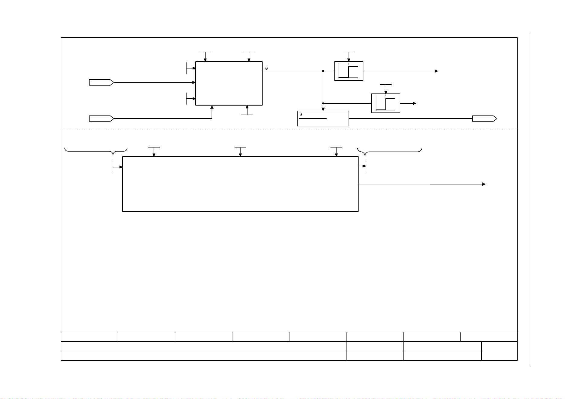
SINAMICS G120C
List Manual (LH13), 04/2014, A5E33840768B AA
439
3 Function diagrams
3.16 Signals and monitoring functions
Fig. 3-103 8017 – Thermal motor models
- 8017 -
Function diagram
87654321
fp_8017_97_05.vsd
Signals and monitoring functions
SINAMICS G120C
07.04.2014 V4.7
Thermal motor models
<1>
0
1
0
1
[8016.4]
<1>
[8016.6]
<2>
<2>
Motor temperature model 1
(I2t)
(for synchronous motor only)
A07012
"Motor temperature model 1/3 overtemperature"
Only if there is a temperature sensor (p0601 > 0).
Only if <1> are not met.
r0035
Mot temp [°C]
model
not smoothed
r0068
I_act abs val [Arms]
[0]
– 40 K
p0605 – 40 K
x 100 [%]
model
<3>
The lower p0611 and the lower the reference current of the thermal motor model 1 (I2t), the faster A07012 is reached.<3>
<4> p0605 also defines the target temperature for p0034 = 100 %.
Therefore, p0605 has no influence on the time up to alarm A07012.
<4>
Mot I_rated
p0305
I2t mot_mod T
p0611
I2t F thresh
p0615
Mot T_ambient
p0625
r0034
Mot_util therm [%]
Mod 1/2 threshold
p0605
[8016.1]
p0612.0 (0)
1 = Activate motor temperature model 1 (I2t)
p0612.1 (1)
1 = Activate motor temperature model 2
Mot T_ambient
p0625
Mot weight th mod
p0344
Mod T_winding [°C]
r0632 [D]
Calculated motor temperaturesRated motor temperature rise
Motor temperature model 2
(for induction motor only)
<5> If p0610 = 12.
Mot temp response
p0610
<5>
Mot temp response
p0610
<5>
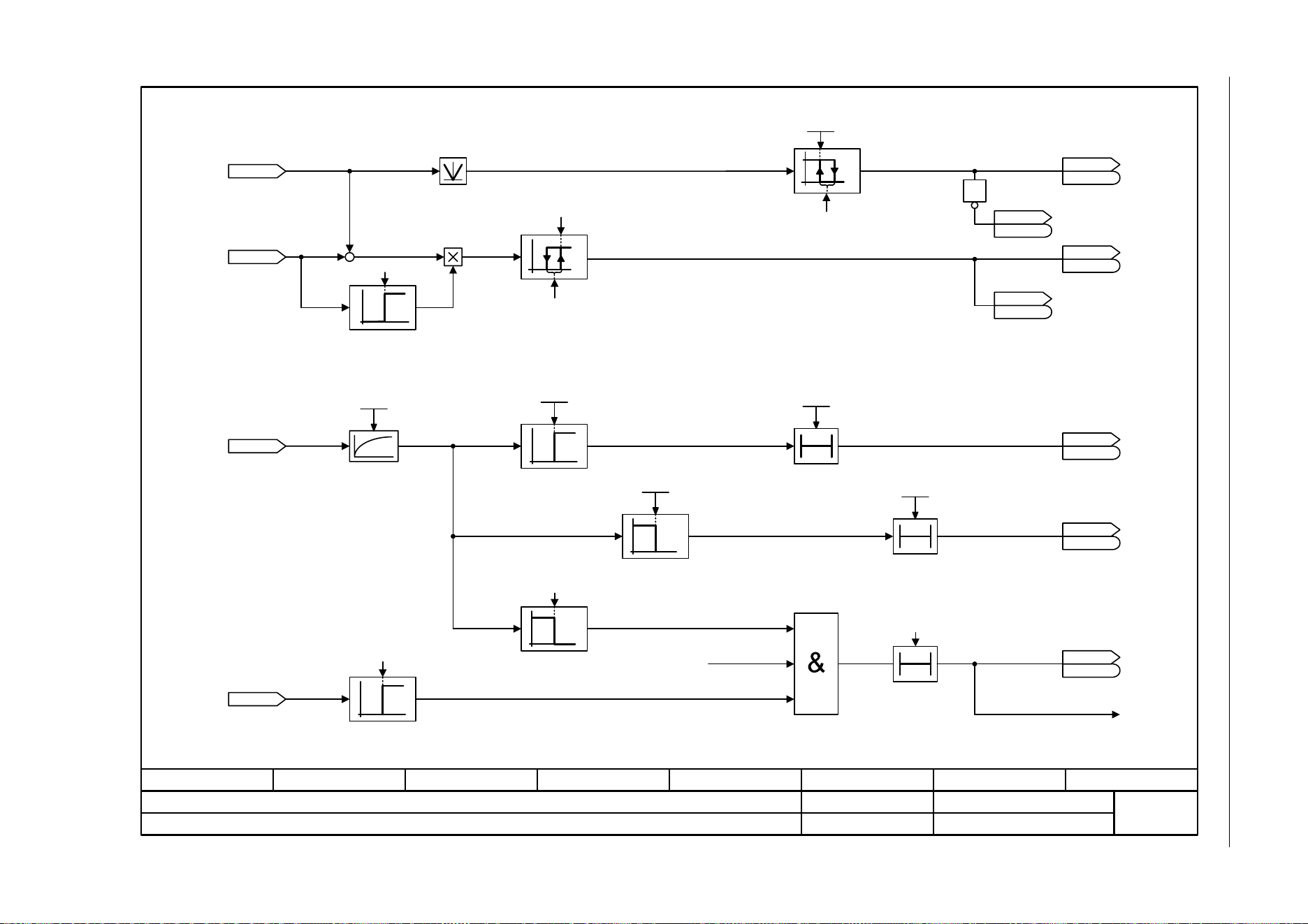
3 Function diagrams
3.16 Signals and monitoring functions
SINAMICS G120C
440 List Manual (LH13), 04/2014, A5E33840768B AA
Fig. 3-104 8020 – Monitoring functions 1
- 8020 -
Function diagram
87654321
fp_8020_97_05.vsd
Signals and monitoring functions
SINAMICS G120C
07.04.2014 V4.7
Monitoring functions 1
0
1
[8010.2]
+
–
[3050.8]
[6714.8]
[6730.4]
[6731.4]
0
1
0
T0
1
0
0
0
1
n_min
p1080
ZSW monitor 1
r2197
r2197
r2169
n_act smth message [rpm]
r1119
RFG setp at inp [rpm]
r0068
I_act abs val [Arms]
r0072
U_output [Vrms]
[2511.6]
[2511.6]
ZSW monitor 1
r2197
r2197
Enable Pulses
1 = |n_act| <= n_min p1080
1 = |n_act| >= n_set
1 = Output load is not
present
Drive: No motor detected
A07929
-1
1
0
[0]
2.00 [1/min]
Hysteresis speed 3
2.00 [1/min]
Hysteresis speed 3
2000 ms
<1> Calculated.
<1>
<1>
1
.0
[2534.2]
[2534.2]
[2534.2]
r2197.4
r2197
r0053.2
r0053
r0053.6
r0053
M_act_filt T
0 ... 1000000 [ms]
p3233 [D] (100)
I_thres
p2170
I_thresh rch t_del
p2171
1
0
0T
0
1
I_thres
p2170
I_thresh rch t_del
p2171
0T
ZSW monitor 2
r2198
r2198
ZSW monitor 1
r2197
r2197
1 = I_act >=
I_threshold value p2170
1 = |I_act| <
I_threshold value p2170
.8
.8
.11
[2534.2]
[2536.2]
p0305 • 3%
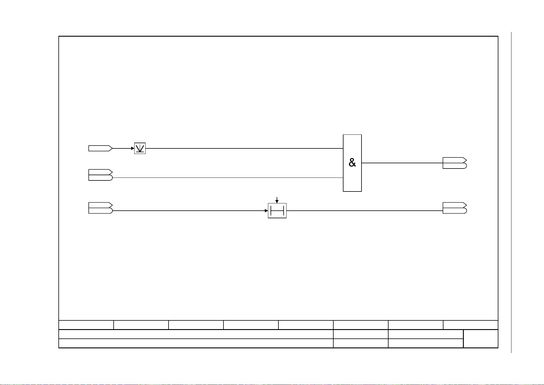
SINAMICS G120C
List Manual (LH13), 04/2014, A5E33840768B AA
441
3 Function diagrams
3.16 Signals and monitoring functions
Fig. 3-105 8021 – Monitoring functions 2
- 8021 -
Function diagram
87654321
fp_8021_97_05.vsd
Signals and monitoring functions
SINAMICS G120C
07.04.2014 V4.7
Monitoring functions 2
[6799.8]
[2534.7]
0T
[2537.7]
r0080
M_act [Nm]
ZSW monitor 3
r2199
r2199
.5
ZSW monitor 1
r2197
r2197
.6
ZSW monitor 2
r2198
r2198
.9
|M_act| > p2174 without
acceleration
ZSW monitor 1
r2197
r2197
|n_act| > n_max delay
Ramp-up/ramp-down completed
|n_act| > n_max
200 [ms]
Delay for comparison
n > n_max
.12
[2534.2]

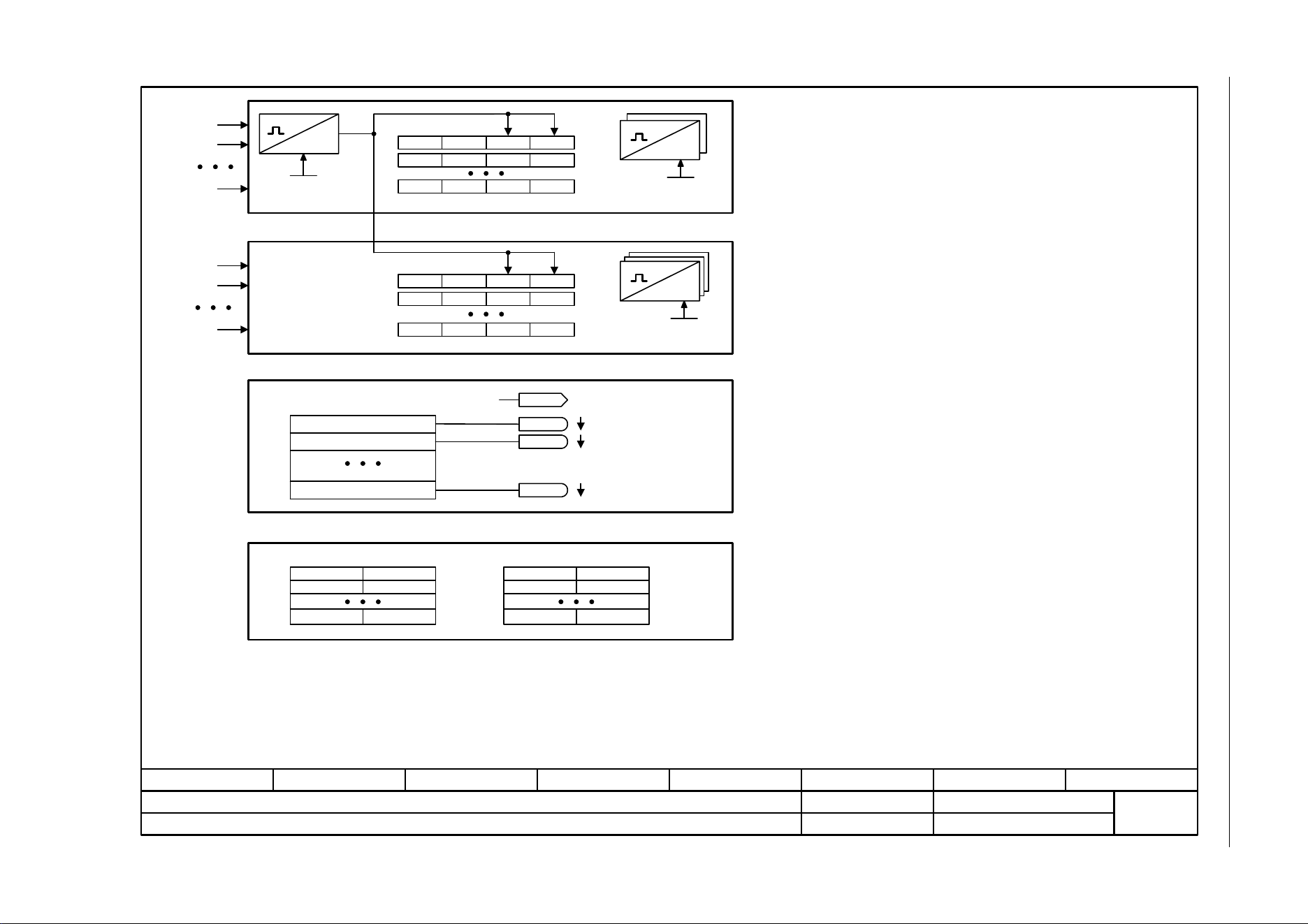
SINAMICS G120C
List Manual (LH13), 04/2014, A5E33840768B AA
443
3 Function diagrams
3.17 Diagnostics
Fig. 3-106 8050 – Overview
- 8050 -
Function diagram
87654321
fp_8050_97_05.vsd
Diagnostics
SINAMICS G120C
07.04.2014 V4.7
Overview
r2109r0948r0949r0945
III
III
III
r2125r2123r2124r2122
III
III
Fxxxxx
Fyyyyy
Axxxxx
Ayyyyy
[0]
[15]
p2128
r2129
p2100[0]
[19]
[1]
p2101 p2126[0]
[19]
[1]
p2127
Fzzzzz
faults
Azzzzz
alarms
[8060] Fault buffer
[8065] Alarm buffer
Code Value coming going
Code Value coming going
[8070] Faults/alarms trigger word
Changes the fault response Changing the acknowledge mode
[8075] Faults/alarms configuration
t_System relative
0 ... 4294967295 [ms]
p0969 (0)
Fault cases qty
0 ... 65535
p0952 (0)
Alarm counter
0 ... 65535
p2111 (0)
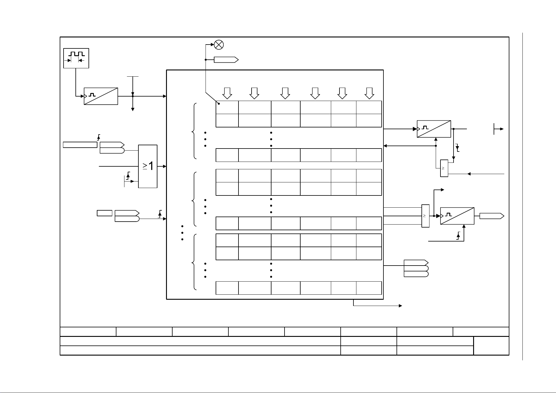
3 Function diagrams
3.17 Diagnostics
SINAMICS G120C
444 List Manual (LH13), 04/2014, A5E33840768B AA
Fig. 3-107 8060 – Fault buffer
- 8060 -
Function diagram
87654321
fp_8060_97_05.vsd
Diagnostics
SINAMICS G120C
07.04.2014 V4.7
Fault buffer
III
1 ms
<1>
[2546.7]
p2103 ... p2104
[2546.7]
p2106
<2>
32 bit counter,
free running
[8065.1]
Operating time
This fault is overwritten when "more recent" faults occur.
The buffer parameters are cyclically updated in the background (refer to the status signal in r2139).
Fault responses to the sequence control
t_System relative
0 ... 4294967295 [ms]
p0969 (0)
POWER ON
Faults ackn DO
p3981
1 = External fault 1
(F07860)
r2138.7
r2138
1 = Acknowledge fault
r2138.13
r2138
<1>
RESET
III
RESET
III
RESET
POWER ON
1
r0949[63] [I32]
r2133[63] [Float]
r0945[0]
r0945[1]
r0945[7]
r0945[56]
r0945[57]
r0945[63]
r0945[8]
r0945[9]
r0945[15]
r0949[0] [I32]
r2133[0] [Float]
r0949[1] [I32]
r2133[1] [Float]
r0949[7] [I32]
r2133[7] [Float]
r0949[56] [I32]
r2133[56] [Float]
r0949[57] [I32]
r2133[57] [Float]
r0949[8] [I32]
r2133[8] [Float]
r0949[9] [I32]
r2133[9] [Float]
r0949[15] [I32]
r2133[15] [Float]
r0948[0] [ms]
r2130[0] [d]
r0948[1] [ms]
r2130[1] [d]
r0948[7] [ms]
r2130[7] [d]
r0948[56] [ms]
r2130[56] [d]
r0948[57] [ms]
r2130[57] [d]
r0948[63] [ms]
r2130[63] [d]
r0948[8] [ms]
r2130[8] [d]
r0948[9] [ms]
r2130[9] [d]
r0948[15] [ms]
r2130[15] [d]
r2109[0] [ms]
r2136[0] [d]
r2109[1] [ms]
r2136[1] [d]
r2109[7] [ms]
r2136[7] [d]
r2109[56] [ms]
r2136[56] [d]
r2109[57] [ms]
r2136[57] [d]
r2109[63] [ms]
r2136[63] [d]
r2109[8] [ms]
r2136[8] [d]
r2109[9] [ms]
r2136[9] [d]
r2109[15] [ms]
r2136[15] [d]
1
<2>
Fault times
Actual
fault case
Faults
Acknowledging
1. Acknow-
ledged
fault case
7. Acknow-
ledged
fault case
[oldest]
Fault
Fault
Fault
Fault code Fault value
Fault time
"received"
Fault time
"removed"
Fault case
appears
Delete fault buffer
Fault disappears
Fault appears
Fault case
acknowl.
Counter
16 bit
p0952 = 0:
Fault buffer is deleted/
cleared
Automatic
16 bit counter,
free running
Fault buffer change [8065.6]
Fault cases qty
0 ... 65535
p0952 (0)
r0944
Fault buff change
3120[0]
3120[1]
3120[7]
3120[56]
3120[57]
3120[63]
3120[8]
3120[9]
3120[15]
r3122[0]
r3122[1]
r3122[7]
r3122[56]
r3122[57]
r3122[63]
r3122[8]
r3122[9]
r3122[15]
Diagnostic
attribute
fault
2
1
8
Fault
Fault
Fault
2
1
8
Fault
Fault
Fault
2
1
8
Component
fault
0 = "No fault present"
LED "RDY" [= red for fault]
r2131
Act fault code
r0945 = 0
r0948 = 0
r0949 = 0
r2109 = 0
r2130 = 0
r2133 = 0
r2136 = 0
r3120 = 0
r3122 = 0
[2548.2]
ZSW fault/alarm 1
r2139
r2139
.3 1 = Fault present
1 = Fault gone/can be acknowledged
r2139.15
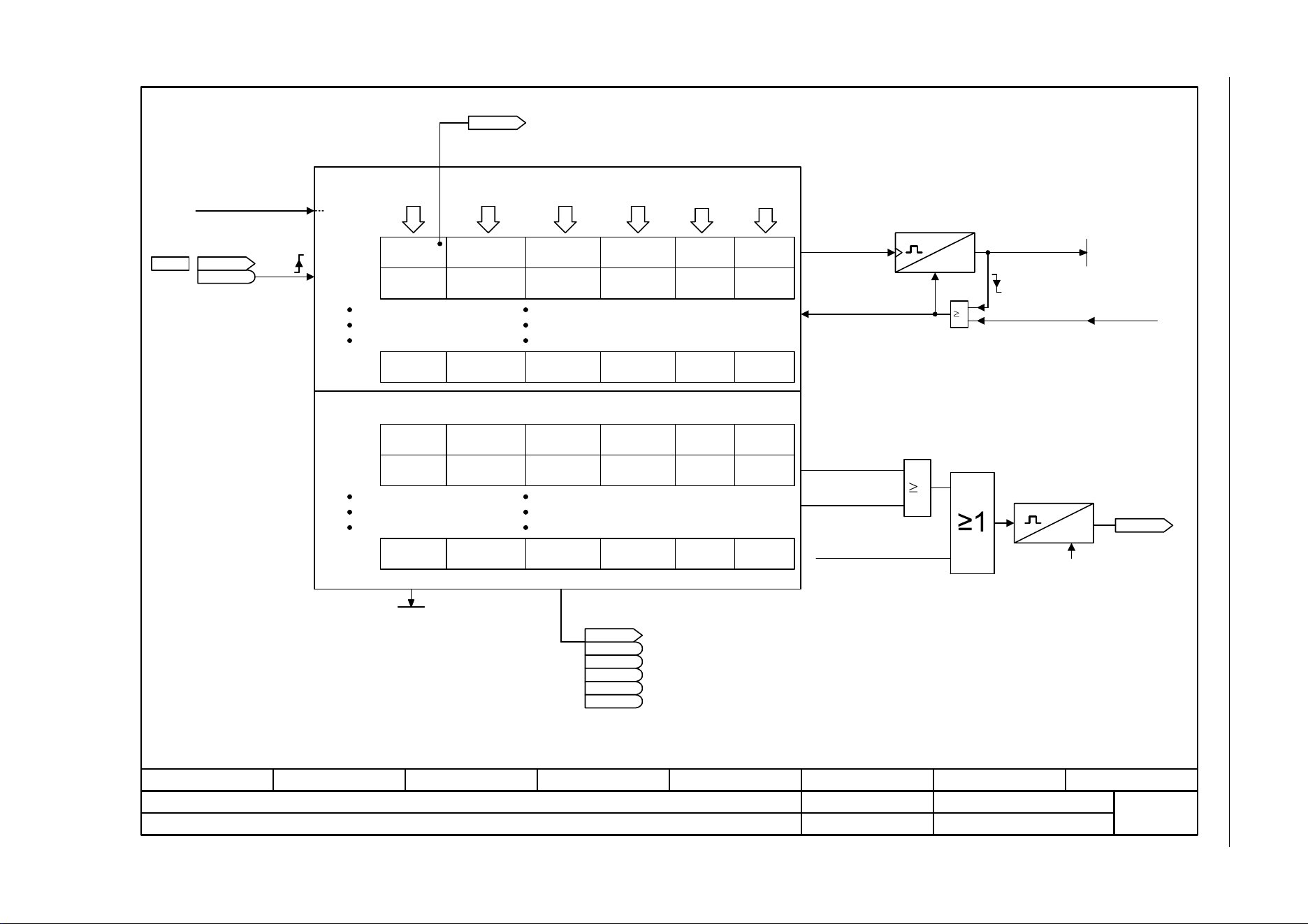
SINAMICS G120C
List Manual (LH13), 04/2014, A5E33840768B AA
445
3 Function diagrams
3.17 Diagnostics
Fig. 3-108 8065 – Alarm buffer
- 8065 -
Function diagram
87654321
fp_8065_97_05.vsd
Diagnostics
SINAMICS G120C
07.04.2014 V4.7
Alarm buffer
RESET
1
III
RESET
[2546.7]
p2112
r2122[0]
r2122[1]
r2122[7]
r2124[0] [I32]
r2134[0] [Float]
r2124[1] [I32]
r2134[1] [Float]
r2124[7] [I32]
r2134[7] [Float]
r2123[0] [ms]
r2123[1] [ms]
r2123[7] [ms]
r2125[0] [ms]
r2125[1] [ms]
r2125[7] [ms]
[8060.1]
POWER ON
r2122[8]
r2122[9]
r2122[63]
r2124[8] [I32]
r2134[8] [Float]
r2124[9] [I32]
r2134[9] [Float]
r2124[63] [I32]
r2134[63] [Float]
r2123[8] [ms]
r2123[9] [ms]
r2123[63] [ms]
r2125[8] [ms]
r2125[9] [ms]
r2125[63] [ms]
<1>
<1>
Operating time
The buffer parameters are updated cyclically in the background (see status signal in r2139).
Alarm times
Alarm 1
(oldest)
Alarm 2
Alarm 8
(most
recent)
Alarm history
Alarm 1
(most
recent)
Alarm 2
Alarm 56
(oldest)
Alarm code Alarm value
Alarm time
"received"
Alarm time
"removed"
Alarms
counter
p2111
p2111 = 0:
Alarm buffer is deleted
Alarm appears
Delete alarm buffer
Counter
16 bit
r2138
r2138
.10
Alarm number
r2110
0 = "No alarm present"
r2132
Actual alarm code
3121[0]
3121[1]
3121[7]
3121[8]
3121[9]
3121[63]
r3123[0]
r3123[1]
r3123[7]
r3123[8]
r3123[9]
r3123[63]
Component
alarm
r2122 = 0
r2123 = 0
r2124 = 0
r2125 = 0
r2134 = 0
r3121 = 0
r3123 = 0
Diagnostic
attribute
alarm
1 = External alarm 1
(A07850)
III
RESET
POWER ON
Fault buffer change
[8060.8]
Alarm
appears
Alarm
disappears
Delete alarm
buffer
16 bit counter,
free running
r2120
Sum buffer changed
1 = Alarm present
ZSW fault/alarm 1
r2139
r2139
.7
[2548.2]
1
1 = Alarm class bit 0
1 = Alarm class bit 1
1 = Maintenance required
1 = Maintenance urgently required
r2139.11
r2139.12
r2139.13
r2139.14
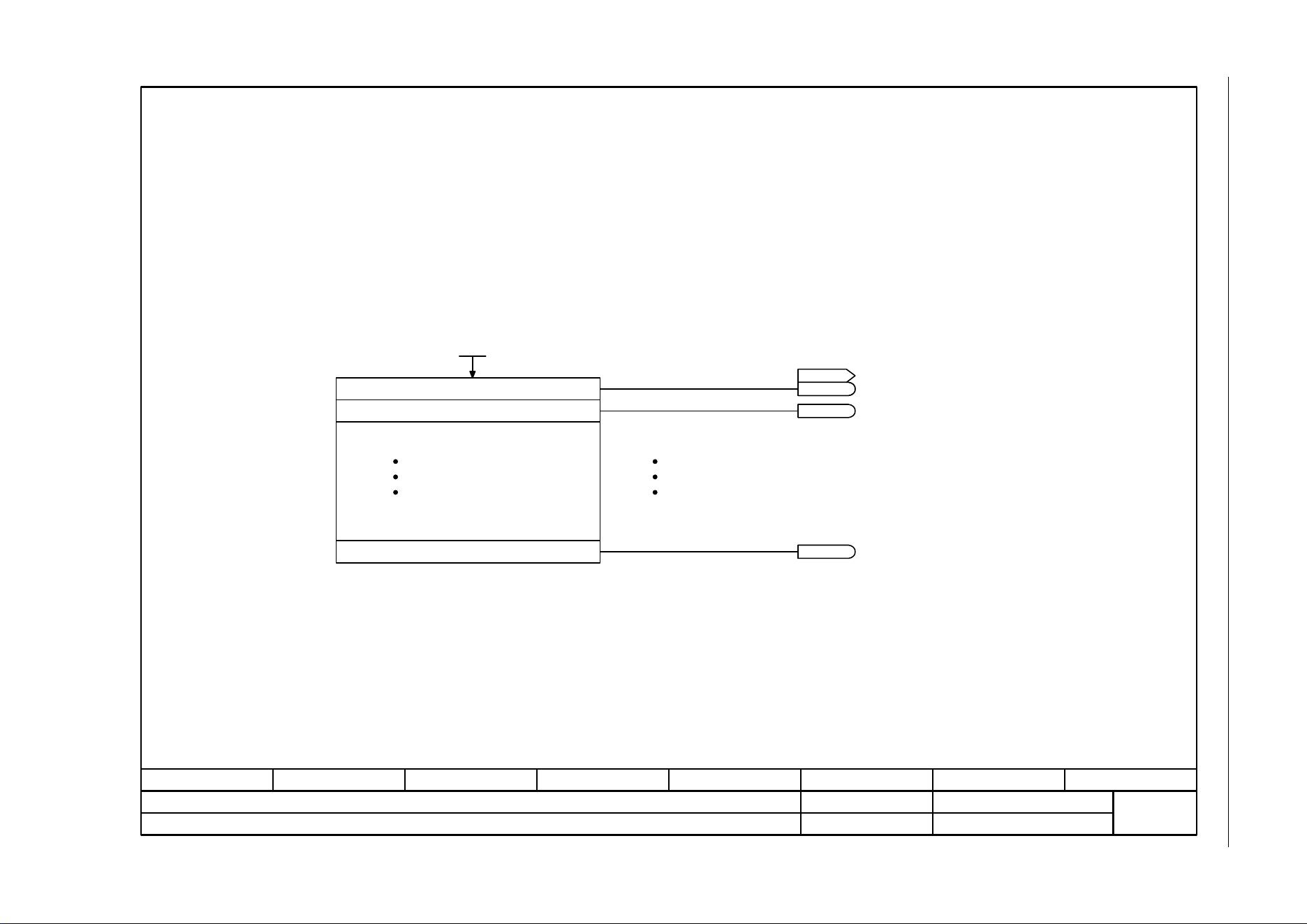
3 Function diagrams
3.17 Diagnostics
SINAMICS G120C
446 List Manual (LH13), 04/2014, A5E33840768B AA
Fig. 3-109 8070 – Faults/alarms trigger word (r2129)
- 8070 -
Function diagram
87654321
fp_8070_97_61.vsd
Diagnostics
SINAMICS G120C
07.04.2014 V4.7
Faults/alarms trigger word (r2129)
[0]
[1]
[15]
r2129.15
r2129.1
0. Fault/alarm code
1. Fault/alarm code
15. Fault/alarm code
Setting fault/alarm trigger
1. Message/signal present
0. Message/signal present
15. Message/signal present
Fault/alarm trigger word
(e.g. as trigger condition to record traces)
F/A trigger sel
0 ... 65535
p2128 (0)
F/A trigger signal
r2129
r2129
r2129.0
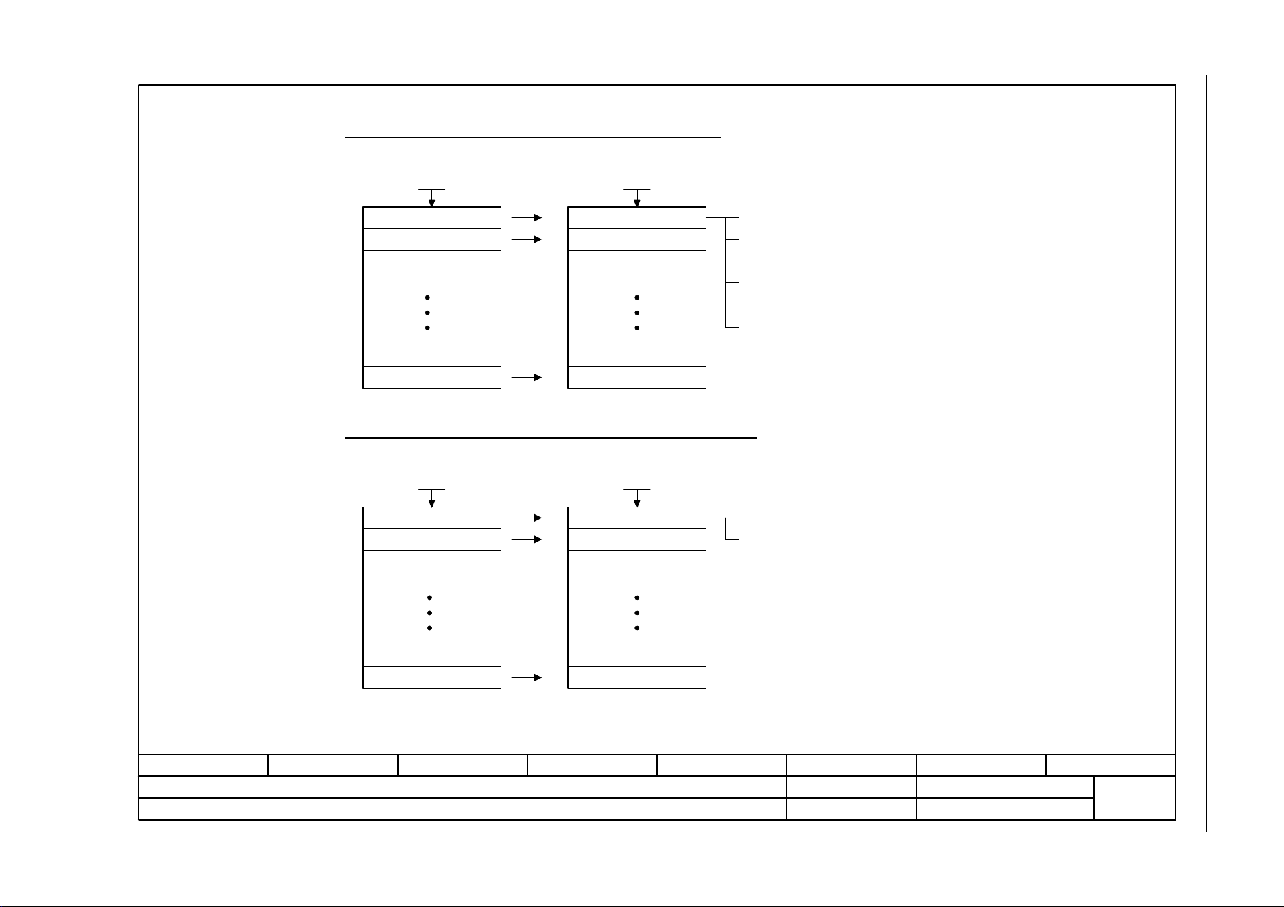
SINAMICS G120C
List Manual (LH13), 04/2014, A5E33840768B AA
447
3 Function diagrams
3.17 Diagnostics
Fig. 3-110 8075 – Faults/alarms configuration
- 8075 -
Function diagram
87654321
fp_8075_97_05.vsd
Diagnostics
SINAMICS G120C
07.04.2014 V4.7
Faults/alarms configuration
[0]
[1]
[19]
[0]
[1]
[19]
[0]
[1]
[19]
[0]
[1]
[19]
<1>
Changing the fault response for maximum 20 faults <1>
Changing the acknowledge mode for maximum 20 faults <1>
0. Fault code
1. Fault code
19. Fault code
Fault response
Fault response
Fault response
0. Fault code
1. Fault code
19. Fault code
0 = NONE
1 = OFF1
2 = OFF2
3 = OFF3
5 = STOP2
6 = IASC/DCBRK
Acknowledge mode
Acknowledge mode
Acknowledge mode
1 = Acknowledgement is only possible using POWER ON
2 = Acknowledgement IMMEDIATELY after the cause has been removed.
The fault response, acknowledge mode and message type for all faults and alarms are set to meaningful default values in the factory setting.
Changes are only possible in specific value ranges specified by SIEMENS.
When the message type is changed, the supplementary information is tranferred from fault value r0949 to alarm value r2124 and vice versa.
Chng resp F_no
0 ... 65535
p2100 (0)
Chng resp resp
0 ... 6
p2101 (0)
Chng ackn F_no
0 ... 65535
p2126 (0)
Chng ackn mode
1 ... 2
p2127 (1)

SINAMICS G120C
List Manual (LH13), 04/2014, A5E33840768B AA
449
3 Function diagrams
3.18 Data sets
Fig. 3-111 8560 – Command Data Sets (CDS)
- 8560 -
Function diagram
87654321
fp_8560_97_05.vsd
Data sets
SINAMICS G120C
07.04.2014 V4.7
Command Data Sets (CDS)
r0836.1
r0050.1
t
t
t
CDS1
CDS0
Example:
Change over command data set
CDS0 --> CDS1
BI: p0810 = "0"
CDS0 selected
r0836.0 = 0
BI: p0810 = "1"
CDS1 selected
r0836.0 = 1
CDS0 effective
r0050.0 = 0
CDS1 effective
r0050.0 = 1
(0)
CDS select., bit 0
p0810
CDS selected
r0836
r0836
.0
CDS effective
r0050
r0050
CDS count
2 ... 2
p0170 (2)
Source CDS
p0809[0] (0)
Start copy process
p0809[2] (0)
Target CDS
p0809[1] (1)
Note
Data sets can only be applied
and cleared when p0010 = 15 is
set.
.0
3 Function diagrams
3.18 Data sets
SINAMICS G120C
450 List Manual (LH13), 04/2014, A5E33840768B AA
Fig. 3-112 8565 – Drive Data Sets (DDS)
- 8565 -
Function diagram
87654321
fp_8565_97_05.vsd
Data sets
SINAMICS G120C
07.04.2014 V4.7
Drive Data Sets (DDS)
DDS1
DDS0
<1>
<1>
A07530 "Drive data set does not exist"
A BICO interconnection to a parameter which is part of a drive data set always influences the currently effective data set.
(0)
DDS select., bit 0
p0820 [C]
DDS count
1 ... 2
p0180 (1)
DDS selected
r0837
r0837
DDS effective
r0051
r0051
Copy DDS, source
p0819[0] (0)
Copy DDS, start
p0819[2] (0)
Copy DDS, target
p0819[1] (1)
Note
Data sets can only be applied
and cleared when p0010 = 15
is set.
.0
.0


4 Faults and alarms
4.1 Overview of faults and alarms
SINAMICS G120C
452 List Manual (LH13), 04/2014, A5E33840768B AA
4.1 Overview of faults and alarms
4.1.1 General information
Display of faults/alarms (messages)
In the case of a fault, the drive signals the corresponding fault(s) and/or alarm(s).
For example, the following methods for displaying faults and alarms are available:
• Display via the fault and alarm buffer with PROFIBUS/PROFINET
• Display online via the commissioning software
• Display and operating unit (e.g. BOP, AOP)
Differences between faults and alarms
The differences between faults and alarms are as follows:
Table 4-1 Differences between faults and alarms
Type Description
Faults What happens when a fault occurs?
• The appropriate fault reaction is triggered.
• Status signal ZSW1.3 is set.
• The fault is entered in the fault buffer.
How are faults eliminated?
• Remove the original cause of the fault.
• Acknowledge the fault.
Alarms What happens when an alarm occurs?
• Status signal ZSW1.7 is set.
• The alarm is entered in the alarm buffer.
How are alarms removed?
• Alarms acknowledge themselves. If the cause of the alarm is no longer
present, they automatically reset themselves.

SINAMICS G120C
List Manual (LH13), 04/2014, A5E33840768B AA
453
4 Faults and alarms
4.1 Overview of faults and alarms
Fault reactions
The following fault reactions are defined:
Table 4-2 Fault reactions
List PROFIdrive Reaction Description
NONE - None No reaction when a fault occurs.
Note
With "Basic positioner" (r0108.4 = 1), the following applies:
When a fault occurs with fault reaction "NONE", an active traversing
task is interrupted and the system switches to tracking mode until the
fault has been rectified and acknowledged.
OFF1 ON/
OFF
Brake along the
ramp-function
generator down
ramp followed by
pulse inhibit
Closed-loop speed control (p1300 = 20, 21)
• n_set = 0 is input immediately to brake the drive along the ramp-
function generator ramp down (p1121).
• When zero speed is detected, the motor holding brake (if
parameterized) is closed (p1215). The pulses are suppressed when
the brake application time (p1217) expires.
Zero speed is detected if the actual speed drops below the
threshold (p1226) or if the monitoring time (p1227) started when the
speed setpoint <= speed threshold (p1226) has expired.
Torque control (p1300 = 22, 23)
• The following applies for torque control:
Reaction as for OFF2.
• When the system switches to torque control with p1501, the
following applies:
No separate braking reaction.
If the actual speed value drops below the speed threshold (p1226)
or the timer stage (p1227) has expired, the motor holding brake (if
one is being used) is closed. The pulses are suppressed when the
brake application time (p1217) expires.
OFF1_
DELAYED
- As for OFF1,
however delayed
Faults with this fault response only become effective after the delay
time in p3136 has expired.
The remaining time up to OFF1 is displayed in r3137.
OFF2 COAST
STOP
Internal/external
pulse inhibit
Closed-loop speed and torque control
• Instantaneous pulse suppression, the drive "coasts" to a standstill.
• The motor holding brake (if one is being used) is closed
immediately.
• Switching on inhibited is activated.

4 Faults and alarms
4.1 Overview of faults and alarms
SINAMICS G120C
454 List Manual (LH13), 04/2014, A5E33840768B AA
OFF3 QUICK
STOP
Braking along the
OFF3 down ramp
followed by pulse
inhibit
Closed-loop speed control (p1300 = 20, 21)
• n_set = 0 is input immediately to brake the drive along the OFF3
ramp down (p1135).
• When zero speed is detected, the motor holding brake (if
parameterized) is closed. The pulses are suppressed when the
closing time of the holding brake (p1217) expires.
Zero speed is detected if the actual speed drops below the
threshold (p1226) or if the monitoring time (p1227) started when the
speed setpoint <= speed threshold (p1226) has expired.
• Switching on inhibited is activated.
Torque control (p1300 = 22, 23)
• Changeover to speed-controlled operation and other reactions as
described for speed-controlled operation.
STOP2 - n_set = 0 • n_set = 0 is input immediately to brake the drive along the OFF3
ramp down (p1135).
• The drive remains in closed-loop speed control.
IASC/
DCBRAKE
-- • For synchronous motors, the following applies:
If a fault occurs with this fault reaction, an internal armature short-
circuit is triggered.
The conditions for p1231 = 4 must be observed.
• For induction motors, the following applies:
If a fault occurs with this fault reaction, DC braking is triggered.
DC braking must have been commissioned (p1230 to p1239).
ENCODER - Internal/external
pulse inhibit
(p0491)
The fault reaction ENCODER is applied as a function of the setting in
p0491.
Factory setting:
p0491 = 0 --> Encoder fault causes OFF2
Notice
When changing p0491, it is imperative that the information in the
description of this parameter is carefully observed.
Table 4-2 Fault reactions, continued
List PROFIdrive Reaction Description

SINAMICS G120C
List Manual (LH13), 04/2014, A5E33840768B AA
455
4 Faults and alarms
4.1 Overview of faults and alarms
Acknowledging faults
The list of faults and alarms specifies how to acknowledge each fault after the cause has been
removed.
Table 4-3 Acknowledging faults
Acknowledgemen
t
Description
POWER ON The fault is acknowledged by a POWER ON (switch drive unit off and on again).
Note
If this action has not removed the fault cause, the fault is displayed again immediately after power up.
IMMEDIATELY Faults can be acknowledged on one drive object (Points 1 to 3) or on all drive objects (Point 4) as
follows:
1 Acknowledge by setting parameter:
p3981 = 0 --> 1
2 Acknowledge via binector inputs:
p2103
p2104
p2105
BI: 1. Acknowledge faults
BI: 2. Acknowledge faults
BI: 3. Acknowledge faults
3 Acknowledge via PROFIBUS control signal:
STW1.7 = 0 --> 1 (edge)
Note
• These faults can also be acknowledged by a POWER ON.
• If the cause of the fault has not been removed, the fault will continue to be displayed after
acknowledgement.
• Safety Integrated faults
The "Safe Torque Off" (STO) function must be deselected before these faults are acknowledged.
PULSE INHIBIT The fault can only be acknowledged when the pulses are inhibited (r0899.11 = 0).
The same options are available for acknowledging as described under acknowledge IMMEDIATELY.

4 Faults and alarms
4.1 Overview of faults and alarms
SINAMICS G120C
456 List Manual (LH13), 04/2014, A5E33840768B AA
4.1.2 Explanation of the list of faults and alarms
The data in the following example has been chosen at random. The information listed below is
the maximum amount of information that a description can contain. Some of the information is
optional.
The "List of faults and alarms" (Page 463) has the following layout:
- - - - - - - - - - - - Start of example - - - - - - - - - - - - - - - - - - - - - - - - - - - - - - - - - - - - - - - - - - - - - - - -
Axxxxx (F, N) Fault location (optional): Name
Message class: Text of the message class (number according to PROFIdrive)
Reaction: NONE
Acknowledgement: NONE
Cause: Description of possible causes.
Fault value (r0949, interpret format): or alarm value (r2124, interpret format): (optional)
Information about fault or alarm values (optional).
Remedy: Description of possible remedies.
- - - - - - - - - - - - End of example - - - - - - - - - - - - - - - - - - - - - - - - - - - - - - - - - - - - - - - - - - - - - - - -
Axxxxx Alarm xxxxx
Axxxxx (F, N) Alarm xxxxx (message type can be changed to F or N)
Fxxxxx Fault xxxxx
Fxxxxx (A, N) Fault xxxxx (report type can be changed to A or N)
Nxxxxx No message
Nxxxxx (A) No message (message type can be changed to A)
Cxxxxx Safety message (separate message buffer)
A message comprises a letter followed by the relevant number.
The meaning of the letters is as follows:
• A means "Alarm"
• F means "Fault"
• N means "No message" or "Internal message"
• C means "Safety message"
The optional brackets indicate whether the type specified for this message can be changed
and which message types can be adjusted via parameters (p2118, p2119).
Information about reaction and acknowledgement is specified independently for a message
with adjustable message type (e.g. reaction to F, acknowledgement for F).
Note
You can change the default properties of a fault or alarm by setting parameters.
References: /BA7/ SINAMICS G120 Operating Instructions
SINAMICS G120C Frequency Converter,
Section "Alarms, faults, and system messages"
The "List of faults and alarms" (Page 463) supplies information referred to the properties of a
message set as default. If the properties of a specific message are changed, the corresponding
information may have to be modified in this list.

SINAMICS G120C
List Manual (LH13), 04/2014, A5E33840768B AA
457
4 Faults and alarms
4.1 Overview of faults and alarms
Fault location (optional): Name
The fault location (optional), the name of the fault or alarm and the message number are all
used to identify the message (e.g. with the commissioning software).
Message class:
For each message, specifies the associated message class with the following structure:
Text of the message class (number according to PROFIdrive)
The message classes are transferred at different interfaces to higher-level control systems and
their associated display and operating units.
The message classes that are available are shown in Table "Message classes and coding of
various diagnostic interfaces" (Page 458). In addition to the text of the message class and their
number according to PROFIdrive – as well as a brief help text regarding the cause and remedy
– they also include information about the various diagnostic interfaces:
• PN (hex)
Specifies the "Channel error type" of the PROFINET channel diagnostics.
When activating the channel diagnostics, using the GSDML file, the texts listed in the table
can be displayed.
• DS1 (dec)
Specifies the bit number in date set DS1 of the diagnostic alarm for SIMATIC S7.
When the diagnostic alarms are activated, the texts listed in the table can be displayed.
• DP (dec)
Specifies the "Error type" of the channel-related diagnostics for PROFIBUS.
When the channel diagnostics are activated, the texts listed in the standard and the GSD
file can be displayed.
• ET 200 (dec)
Specifies the "Error type" of the channel-related diagnostics for the
SIMATIC ET 200pro FC-2 device.
When the channel diagnostics are activated, the texts listed in the standard and the GSD
file of the ET 200pro can be displayed.
• NAMUR (r3113.x)
Specifies the bit number in parameter r3113.
For the interfaces DP, ET 200, NAMUR, in some instances, the message classes are
combined.

4 Faults and alarms
4.1 Overview of faults and alarms
SINAMICS G120C
458 List Manual (LH13), 04/2014, A5E33840768B AA
Table 4-4 Message classes and coding of various diagnostic interfaces
Text of the message class (number according to PROFIdrive)
Cause and remedy.
Diagnostics interface
PN
(hex)
DS1
(dec)
DP
(dec)
ET 200
(dec)
NAMUR
(r3113.x)
Hardware/software errors (1)
A hardware or software malfunction was detected. Carry out a
POWER ON for the relevant component. If it occurs again, contact the
hotline.
9000 0 16 9 0
Line fault (2)
A line supply fault has occurred (phase failure, voltage level ...).
Check the line supply and fuses. Check the supply voltage. Check the
wiring.
9001 1 17 24 1
Supply voltage fault (3)
An electronics supply voltage fault (48 V, 24 V, 5 V …) was detected.
Check the wiring. Check the voltage level.
9002 2 2
1
3
2
2
1
3
2
15
DC-link overvoltage (4)
The DC-link voltage has assumed an inadmissibly high value. Check
the dimensioning of the system (line supply, reactor, voltages). Check
the infeed settings.
9003 3 18 24 2
Power electronics fault (5)
An impermissible operating state of the power electronics was
detected (overcurrent, overtemperature, IGBT failure …). Check
compliance with the permissible load cycles. Check the ambient
temperatures (fan).
9004 4 19 24 3
Overtemperature of the electronic component (6)
The temperature in the component has exceeded the highest
permissible limit. Check the ambient temperature / control cabinet
ventilation.
9005 5 20 5 4
Ground fault / inter-phase short-circuit detected (7)
A ground fault / inter-phase short-circuit was detected in the power
cables or in the motor windings. Check the power cables (connection).
Check the motor.
9006 6 21 20 5
Motor overload (8)
The motor was operated outside the permissible limits (temperature,
current, torque …). Check the load cycles and set limits. Check the
ambient temperature / motor cooling.
9007 7 22 24 6
Communication to the higher-level controller faulted (9)
The communication to the higher-level controller (internal coupling,
PROFIBUS, PROFINET …) is faulted or interrupted. Check the state
of the higher-level controller. Check the communication
connection/-wiring. Check the bus configuration/cycles.
9008 8 23 19 7
Safety monitoring channel has detected an error (10)
A safe operation monitoring function has detected an error.
9009 9 24 25 8
Actual position/speed value incorrect or not available (11)
An illegal signal state was detected while evaluating the encoder
signals (track signals, zero marks, absolute values …). Check the
encoder / state of the encoder signals. Observe the maximum
permissible frequencies.
900A 10 25 29 9

SINAMICS G120C
List Manual (LH13), 04/2014, A5E33840768B AA
459
4 Faults and alarms
4.1 Overview of faults and alarms
Internal (DRIVE-CLiQ) communication faulted (12)
The internal communication between the SINAMICS components is
faulted or interrupted. Check the DRIVE-CLiQ wiring. Ensure an EMC-
compliant installation. Observe the maximum permissible quantity
structures / cycles.
900B 11 26 31 10
Infeed fault (13)
The infeed is faulty or has failed. Check the infeed and its environment
(line supply, filters, reactors, fuses …). Check the infeed control.
900C 12 27 24 11
Braking controller / Braking Module faulted (14)
The internal or external Braking Module is faulted or overloaded
(temperature). Check the connection/state of the Braking Module.
Comply with the permissible number of braking operations and their
duration.
900D 13 28 24 15
Line filter fault (15)
The line filter monitoring has detected an excessively high
temperature or another impermissible state. Check the temperature /
temperature monitoring. Check the configuration to ensure that it is
permissible (filter type, infeed, thresholds).
900E 14 17 24 15
External measured value / signal state outside of the permissible
range (16)
A measured value / signal state read in via the input area
(digital/analog/temperature) has assumed an impermissible
value/state. Identify and check the relevant signal. Check the set
thresholds.
900F15292615
Application / technological function faulty (17)
The application / technological function has exceeded a (set) limit
(position, velocity, torque …). Identify and check the relevant limit.
Check the setpoint specification of the higher-level controller.
9010 16 30 9 15
Error in the parameterization/configuration/commissioning
procedure (18)
An error was identified in the parameterization or in a commissioning
procedure, or the parameterization does not match the actual device
configuration. Determine the precise cause of the fault using the
commissioning tool. Adapt the parameterization or device
configuration.
9011 17 31 16 15
General drive fault (19)
Group fault. Determine the precise cause of the fault using the
commissioning tool.
9012 18 9 9 15
Auxiliary unit fault (20)
The monitoring of an auxiliary unit (incoming transformer, cooling
unit …) has detected an illegal state. Determine the exact cause of the
fault and check the relevant device.
9013 19 29 26 15
1. Undervoltage condition of the electronics power supply
2. Overvoltage condition of the electronics power supply
Table 4-4 Message classes and coding of various diagnostic interfaces, continued
Text of the message class (number according to PROFIdrive)
Cause and remedy.
Diagnostics interface
PN
(hex)
DS1
(dec)
DP
(dec)
ET 200
(dec)
NAMUR
(r3113.x)

4 Faults and alarms
4.1 Overview of faults and alarms
SINAMICS G120C
460 List Manual (LH13), 04/2014, A5E33840768B AA
Reaction: Default fault reaction (adjustable fault reaction)
Specifies the default reaction in the event of a fault.
The optional parentheses indicate whether the default fault reactions can be changed and
which fault reactions can be adjusted via parameters (p2100, p2101).
Acknowledgement: Default acknowledgement (adjustable acknowledgement)
Specifies the default method of acknowledging faults after the cause has been eliminated.
The optional parentheses indicate whether the default acknowledgement can be changed and
which acknowledgement can be adjusted via parameters (p2126, p2127).
Cause:
Describes the possible causes of the fault or alarm. A fault or alarm value can also be specified
(optional).
Fault value (r0949, format):
The fault value is entered into the fault buffer in r0949[0...63] and specifies additional, more
precise information about a fault.
Alarm value (r2124, format):
The alarm value specifies additional, more precise information about an alarm.
The alarm value is entered in the alarm buffer in r2124[0...7] and specifies additional, more
precise information about an alarm.
Remedy:
Description of the methods available for eliminating the cause of the active fault/alarm
Note
See Table "Fault reactions" (Page 453)
Note
See Table "Acknowledging faults" (Page 455)
WARNING
In certain cases, service and maintenance personnel are responsible for choosing a suitable
method for eliminating the cause of faults.

SINAMICS G120C
List Manual (LH13), 04/2014, A5E33840768B AA
461
4 Faults and alarms
4.1 Overview of faults and alarms
4.1.3 Number ranges of faults and alarms
Faults and alarms are organized into the following number ranges:
Note
The following number ranges represent an overview of all faults and alarms used in the
SINAMICS drive family.
The faults and alarms for the product described in this List Manual are described in detail in
"List of faults and alarms" (Page 463).
Table 4-5 Number ranges of faults and alarms
of To Area
1000 3999 Control Unit
4000 4999 Reserved
5000 5999 Power section
6000 6899 Infeed
6900 6999 Braking Module
7000 7999 Drive
8000 8999 Option Board
9000 12999 Reserved
13000 13020 Licensing
13021 13099 Reserved
13100 13102 Know-how protection
13103 19999 Reserved
20000 29999 OEM
30000 30999 DRIVE-CLiQ component power unit
31000 31999 DRIVE-CLiQ component encoder 1
32000 32999 DRIVE-CLiQ component encoder 2
Note
Faults that occur are automatically output as an alarm if the encoder is
parameterized as a direct measuring system and does not intervene in
the motor control.
33000 33999 DRIVE-CLiQ component encoder 3
Note
Faults that occur are automatically output as an alarm if the encoder is
parameterized as a direct measuring system and does not intervene in
the motor control.
34000 34999 Voltage Sensing Module (VSM)
35000 35199 Terminal Module 54F (TM54F)
35200 35999 Terminal Module 31 (TM31)
36000 36999 DRIVE-CLiQ Hub Module
37000 37999 HF Damping Module

4 Faults and alarms
4.1 Overview of faults and alarms
SINAMICS G120C
462 List Manual (LH13), 04/2014, A5E33840768B AA
40000 40999 Controller Extension 32 (CX32)
41000 48999 Reserved
49000 49999 SINAMICS GM/SM/GL
50000 50499 Communication Board (COMM BOARD)
50500 59999 OEM Siemens
60000 65535 SINAMICS DC MASTER (closed-loop DC current control)
Table 4-5 Number ranges of faults and alarms, continued
of To Area

SINAMICS G120C
List Manual (LH13), 04/2014, A5E33840768B AA
463
4 Faults and alarms
4.2 List of faults and alarms
4.2 List of faults and alarms
Product: SINAMICS G120C, Version: 4702900, Language: eng
Objects: G120C_CAN, G120C_DP, G120C_PN, G120C_USS
F01000 Internal software error
Message class: Hardware / software error (1)
Reaction: OFF2
Acknowledge: POWER ON
Cause: An internal software error has occurred.
Fault value (r0949, interpret hexadecimal):
Only for internal Siemens troubleshooting.
Remedy: - evaluate fault buffer (r0945).
- carry out a POWER ON (power off/on) for all components.
- if required, check the data on the non-volatile memory (e.g. memory card).
- upgrade firmware to later version.
- contact the Hotline.
- replace the Control Unit.
F01001 FloatingPoint exception
Message class: Hardware / software error (1)
Reaction: OFF2
Acknowledge: POWER ON
Cause: An exception occurred during an operation with the FloatingPoint data type.
The error may be caused by the basic system or an OA application (e.g., FBLOCKS, DCC).
Fault value (r0949, interpret hexadecimal):
Only for internal Siemens troubleshooting.
Note:
Refer to r9999 for further information about this fault.
r9999[0]: Fault number.
r9999[1]: Program counter at the time when the exception occurred.
r9999[2]: Cause of the FloatingPoint exception.
Bit 0 = 1: Operation invalid
Bit 1 = 1: Division by zero
Bit 2 = 1: Overflow
Bit 3 = 1: Underflow
Bit 4 = 1: Inaccurate result
Remedy: - carry out a POWER ON (power off/on) for all components.
- check configuration and signals of the blocks in FBLOCKS.
- check configuration and signals of DCC charts.
- upgrade firmware to later version.
- contact the Hotline.
F01002 Internal software error
Message class: Hardware / software error (1)
Reaction: OFF2
Acknowledge: IMMEDIATELY
Cause: An internal software error has occurred.
Fault value (r0949, interpret hexadecimal):
Only for internal Siemens troubleshooting.
Remedy: - carry out a POWER ON (power off/on) for all components.
- upgrade firmware to later version.
- contact the Hotline.

4 Faults and alarms
4.2 List of faults and alarms
SINAMICS G120C
464 List Manual (LH13), 04/2014, A5E33840768B AA
F01003 Acknowledgement delay when accessing the memory
Message class: Hardware / software error (1)
Reaction: OFF2
Acknowledge: IMMEDIATELY
Cause: A memory area was accessed that does not return a "READY".
Fault value (r0949, interpret hexadecimal):
Only for internal Siemens troubleshooting.
Remedy: - carry out a POWER ON (power off/on) for all components.
- contact the Hotline.
N01004 (F, A) Internal software error
Message class: Hardware / software error (1)
Reaction: NONE
Acknowledge: NONE
Cause: An internal software error has occurred.
Fault value (r0949, hexadecimal):
Only for internal Siemens troubleshooting.
Remedy: - read out diagnostics parameter (r9999).
- contact the Hotline.
F01005 File upload/download error
Message class: Hardware / software error (1)
Reaction: NONE
Acknowledge: IMMEDIATELY
Cause: The upload or download of EEPROM data was unsuccessful.
Fault value (r0949, interpret hexadecimal):
yyxxxx hex: yy = component number, xxxx = fault cause
xxxx = 000B hex = 11 dec:
Power unit component has detected a checksum error.
xxxx = 000F hex = 15 dec:
The selected power unit will not accept the content of the EEPROM file.
xxxx = 0011 hex = 17 dec:
Power unit component has detected an internal access error.
xxxx = 0012 hex = 18 dec:
After several communication attempts, no response from the power unit component.
xxxx = 008B hex = 140 dec:
EEPROM file for the power unit component not available on the memory card.
xxxx = 008D hex = 141 dec:
An inconsistent length of the firmware file was signaled. It is possible that the download/upload has been interrupted.
xxxx = 0090 hex = 144 dec:
When checking the file that was loaded, the component detected a fault (checksum). It is possible that the file on the
memory card is defective.
xxxx = 0092 hex = 146 dec:
This SW or HW does not support the selected function.
xxxx = 009C hex = 156 dec:
Component with the specified component number is not available (p7828).
xxxx = Additional values:
Only for internal Siemens troubleshooting.
Remedy: Save a suitable firmware file or EEPROM file for upload or download in folder "/ee_sac/" on the memory card.
A01009 (N) CU: Control module overtemperature
Message class: Overtemperature of the electronic components (6)
Reaction: NONE
Acknowledge: NONE
Cause: The temperature (r0037[0]) of the control module (Control Unit) has exceeded the specified limit value.

SINAMICS G120C
List Manual (LH13), 04/2014, A5E33840768B AA
465
4 Faults and alarms
4.2 List of faults and alarms
Remedy: - check the air intake for the Control Unit.
- check the Control Unit fan.
Note:
The alarm automatically disappears after the limit value has been undershot.
F01010 Drive type unknown
Message class: Error in the parameterization / configuration / commissioning procedure (18)
Reaction: NONE
Acknowledge: IMMEDIATELY
Cause: An unknown drive type was found.
Remedy: - replace Power Module.
- carry out a POWER ON (power off/on).
- upgrade firmware to later version.
- contact the Hotline.
F01015 Internal software error
Message class: Hardware / software error (1)
Reaction: OFF2
Acknowledge: POWER ON
Cause: An internal software error has occurred.
Fault value (r0949, interpret decimal):
Only for internal Siemens troubleshooting.
Remedy: - carry out a POWER ON (power off/on) for all components.
- upgrade firmware to later version.
- contact the Hotline.
A01016 (F) Firmware changed
Message class: Hardware / software error (1)
Reaction: NONE
Acknowledge: NONE
Cause: At least one firmware file in the directory was illegally changed on the non-volatile memory (memory card/device
memory) with respect to the version when shipped from the factory.
Alarm value (r2124, interpret decimal):
0: Checksum of one file is incorrect.
1: File missing.
2: Too many files.
3: Incorrect firmware version.
4: Incorrect checksum of the back-up file.
Remedy: For the non-volatile memory for the firmware (memory card/device memory), restore the delivery condition.
Note:
The file involved can be read out using parameter r9925.
The status of the firmware check is displayed using r9926.
A01017 Component lists changed
Message class: Hardware / software error (1)
Reaction: NONE
Acknowledge: NONE
Cause: On the memory card, one file in the directory /SIEMENS/SINAMICS/DATA or /ADDON/SINAMICS/DATA has been
illegally changed with respect to that supplied from the factory. No changes are permitted in this directory.
Alarm value (r2124, interpret decimal):
zyx dec: x = Problem, y = Directory, z = File name
x = 1: File does not exist.
x = 2: Firmware version of the file does not match the software version.
x = 3: File checksum is incorrect.
y = 0: Directory /SIEMENS/SINAMICS/DATA/
y = 1: Directory /ADDON/SINAMICS/DATA/

4 Faults and alarms
4.2 List of faults and alarms
SINAMICS G120C
466 List Manual (LH13), 04/2014, A5E33840768B AA
z = 0: File MOTARM.ACX
z = 1: File MOTSRM.ACX
z = 2: File MOTSLM.ACX
z = 3: File ENCDATA.ACX
z = 4: File FILTDATA.ACX
z = 5: File BRKDATA.ACX
z = 6: File DAT_BEAR.ACX
z = 7: File CFG_BEAR.ACX
Remedy: For the file on the memory card involved, restore the status originally supplied from the factory.
F01018 Booting has been interrupted several times
Message class: Hardware / software error (1)
Reaction: NONE
Acknowledge: POWER ON
Cause: Module booting was interrupted several times. As a consequence, the module boots with the factory setting.
Possible reasons for booting being interrupted:
- power supply interrupted.
- CPU crashed.
- parameterization invalid.
Remedy: - carry out a POWER ON (power off/on). After switching on, the module reboots from the valid parameterization (if
available).
- restore the valid parameterization.
Examples:
a) Carry out a first commissioning, save, carry out a POWER ON (switch-off/switch-on).
b) Load another valid parameter backup (e.g. from the memory card), save, carry out a POWER ON (switch-
off/switch-on).
Note:
If the fault situation is repeated, then this fault is again output after several interrupted boots.
A01019 Writing to the removable data medium unsuccessful
Message class: Hardware / software error (1)
Reaction: NONE
Acknowledge: NONE
Cause: The write access to the removable data medium was unsuccessful.
Remedy: Remove and check the removable data medium. Then run the data backup again.
A01020 Writing to RAM disk unsuccessful
Message class: Hardware / software error (1)
Reaction: NONE
Acknowledge: NONE
Cause: A write access to the internal RAM disk was unsuccessful.
Remedy: Adapt the file size for the system logbook to the internal RAM disk (p9930).
A01021 Removable data medium as USB data storage medium from the PC used
Message class: General drive fault (19)
Reaction: NONE
Acknowledge: NONE
Cause: The removable data medium is used as USB data storage medium from a PC
As a consequence, the drive cannot access the removable data medium. When backing up, the configuration data
cannot be saved on the removable data medium.
Fault value (r0949, interpret decimal):
1: The know-how protection as well as the copy protection for the removable data medium is active. Backup is
inhibited.
2: The configuration data are only backed up in the Control Unit.
See also: r7760 (Write protection/know-how protection status), r9401 (Safely remove memory card status)

SINAMICS G120C
List Manual (LH13), 04/2014, A5E33840768B AA
467
4 Faults and alarms
4.2 List of faults and alarms
Remedy: Deactivate the USB connection to the PC and back up the configuration data.
Note:
The alarm is automatically canceled when disconnecting the USB connection or when removing the removable data
medium.
See also: r9401 (Safely remove memory card status)
F01023 Software timeout (internal)
Message class: Hardware / software error (1)
Reaction: NONE
Acknowledge: IMMEDIATELY
Cause: An internal software timeout has occurred.
Fault value (r0949, interpret decimal):
Only for internal Siemens troubleshooting.
Remedy: - carry out a POWER ON (power off/on) for all components.
- upgrade firmware to later version.
- contact the Hotline.
A01028 (F) Configuration error
Message class: Error in the parameterization / configuration / commissioning procedure (18)
Reaction: NONE
Acknowledge: NONE
Cause: The parameterization that was downloaded was generated with a different module type (Order No., MLFB).
Remedy: Save parameters in a non-volatile fashion (p0971 = 1).
F01030 Sign-of-life failure for master control
Message class: Communication error to the higher-level control system (9)
Reaction: OFF3 (IASC/DCBRK, NONE, OFF1, OFF2, STOP2)
Acknowledge: IMMEDIATELY
Cause: For active PC master control, no sign-of-life was received within the monitoring time.
The master control was returned to the active BICO interconnection.
Remedy: Set the monitoring time higher at the PC or, if required, completely disable the monitoring function.
For the commissioning software, the monitoring time is set as follows:
<Drive> -> Commissioning -> Control panel -> Button "Fetch master control" -> A window is displayed to set the
monitoring time in milliseconds.
Notice:
The monitoring time should be set as short as possible. A long monitoring time means a late response when the
communication fails!
F01033 Units changeover: Reference parameter value invalid
Message class: Error in the parameterization / configuration / commissioning procedure (18)
Reaction: NONE
Acknowledge: IMMEDIATELY
Cause: When changing over the units to the referred representation type, it is not permissible for any of the required
reference parameters to be equal to 0.0
Fault value (r0949, parameter):
Reference parameter whose value is 0.0.
See also: p0505 (Selecting the system of units), p0595 (Technological unit selection)
Remedy: Set the value of the reference parameter to a number different than 0.0.
See also: p0304, p0305, p0310, p0596, p2000, p2001, p2002, p2003, r2004
F01034 Units changeover: Calculation parameter values after reference value change
unsuccessful
Message class: Error in the parameterization / configuration / commissioning procedure (18)
Reaction: NONE
Acknowledge: IMMEDIATELY
Cause: The change of a reference parameter meant that for an involved parameter the selected value was not able to be re-
calculated in the per unit representation. The change was rejected and the original parameter value restored.

4 Faults and alarms
4.2 List of faults and alarms
SINAMICS G120C
468 List Manual (LH13), 04/2014, A5E33840768B AA
Fault value (r0949, parameter):
Parameter whose value was not able to be re-calculated.
See also: p0304, p0305, p0310, p0596, p2000, p2001, p2002, p2003, r2004
Remedy: - Select the value of the reference parameter such that the parameter involved can be calculated in the per unit
representation.
- Technology unit selection (p0595) before changing the reference parameter p0596, set p0595 = 1.
See also: p0304, p0305, p0310, p0596, p2000, p2001, p2002, p2003, r2004
A01035 (F) ACX: Parameter back-up file corrupted
Message class: Hardware / software error (1)
Reaction: NONE
Acknowledge: NONE
Cause: When the Control Unit is booted, no complete data set was found from the parameter back-up files. The last time that
the parameterization was saved, it was not completely carried out.
It is possible that the backup was interrupted by switching off or withdrawing the memory card.
Alarm value (r2124, interpret hexadecimal):
ddccbbaa hex:
aa = 01 hex:
Power up was realized without data backup. The drive is in the factory setting.
aa = 02 hex:
The last available internal backup data record was loaded. The parameterization must be checked. It is
recommended that the parameterization is downloaded again.
aa = 03 hex:
The last available data record from the memory card was loaded. The parameterization must be checked.
aa = 04 hex:
An invalid data backup was loaded from the memory card into the drive. The drive is in the factory setting.
dd, cc, bb:
Only for internal Siemens troubleshooting.
See also: p0971 (Save parameters)
Remedy: - Download the project again with the commissioning software.
- save all parameters (p0971 = 1 or "copy RAM to ROM").
F01036 (A) ACX: Parameter back-up file missing
Message class: Hardware / software error (1)
Reaction: NONE (OFF1, OFF2, OFF3)
Acknowledge: IMMEDIATELY
Cause: When downloading the device parameterization, a parameter back-up file PSxxxyyy.ACX associated with a drive
object cannot be found.
Fault value (r0949, interpret hexadecimal):
Byte 1: yyy in the file name PSxxxyyy.ACX
yyy = 000 --> consistency back-up file
yyy = 001 ... 062 --> drive object number
yyy = 099 --> PROFIBUS parameter back-up file
Byte 2, 3, 4:
Only for internal Siemens troubleshooting.
Remedy: If you have saved the project data using the commissioning software, carry out a new download for your project.
Save using the function "Copy RAM to ROM" or with p0971 = 1
This means that the parameter files are again completely written into the non-volatile memory.
Note:
If the project data have not been backed up, then a new first commissioning is required.

SINAMICS G120C
List Manual (LH13), 04/2014, A5E33840768B AA
469
4 Faults and alarms
4.2 List of faults and alarms
F01038 (A) ACX: Loading the parameter back-up file unsuccessful
Message class: Hardware / software error (1)
Reaction: NONE (OFF1, OFF2, OFF3)
Acknowledge: IMMEDIATELY
Cause: An error has occurred when downloading PSxxxyyy.ACX or PTxxxyyy.ACX files from the non-volatile memory.
Fault value (r0949, interpret hexadecimal):
Byte 1: yyy in the file name PSxxxyyy.ACX
yyy = 000 --> consistency back-up file
yyy = 001 ... 062 --> drive object number
yyy = 099 --> PROFIBUS parameter back-up file
Byte 2:
255: Incorrect drive object type.
254: Topology comparison unsuccessful -> drive object type was not able to be identified.
Reasons could be:
- Incorrect component type in the actual topology
- Component does not exist in the actual topology.
- Component not active.
Additional values:
Only for internal Siemens troubleshooting.
Byte 4, 3:
Only for internal Siemens troubleshooting.
Remedy: - If you have saved the project data using the commissioning software, download the project again. Save using the
function "Copy RAM to ROM" or with p0971 = 1 so that all of the parameter files are again completely written to the
non-volatile memory.
- replace the memory card or Control Unit.
F01039 (A) ACX: Writing to the parameter back-up file was unsuccessful
Message class: Hardware / software error (1)
Reaction: NONE (OFF1, OFF2, OFF3)
Acknowledge: IMMEDIATELY
Cause: Writing to at least one parameter back-up file PSxxxyyy.*** in the non-volatile memory was unsuccessful.
- In the directory /USER/SINAMICS/DATA/ at least one parameter back-up file PSxxxyyy.*** has the "read only" file
attribute and cannot be overwritten.
- There is not sufficient free memory space available.
- The non-volatile memory is defective and cannot be written to.
Fault value (r0949, interpret hexadecimal):
dcba hex
a = yyy in the file names PSxxxyyy.***
a = 000 --> consistency back-up file
a = 001 ... 062 --> drive object number
a = 099 --> PROFIBUS parameter back-up file
b = xxx in the file names PSxxxyyy.***
b = 000 --> data save started with p0971 = 1
b = 010 --> data save started with p0971 = 10
b = 011 --> data save started with p0971 = 11
b = 012 --> data save started with p0971 = 12
d, c:
Only for internal Siemens troubleshooting.
Remedy: - check the file attribute of the files (PSxxxyyy.***, CAxxxyyy.***, CCxxxyyy.***) and, if required, change from "read
only" to "writeable".
- check the free memory space in the non-volatile memory. Approx. 80 kbyte of free memory space is required for
every drive object in the system.
- replace the memory card or Control Unit.

4 Faults and alarms
4.2 List of faults and alarms
SINAMICS G120C
470 List Manual (LH13), 04/2014, A5E33840768B AA
F01040 Save parameter settings and carry out a POWER ON
Message class: Error in the parameterization / configuration / commissioning procedure (18)
Reaction: OFF2
Acknowledge: POWER ON
Cause: A parameter has been changed that requires the parameters to be backed up and the Control Unit to be switched
OFF and ON again.
Remedy: - Save parameters (p0971).
- carry out a POWER ON (power off/on) for the Control Unit.
F01042 Parameter error during project download
Message class: Error in the parameterization / configuration / commissioning procedure (18)
Reaction: OFF2 (NONE, OFF1, OFF3)
Acknowledge: IMMEDIATELY
Cause: An error was detected when downloading a project using the commissioning software (e.g. incorrect parameter
value).
For the specified parameter, it was detected that dynamic limits were exceeded that may possibly depend on other
parameters.
Fault value (r0949, interpret hexadecimal):
ccbbaaaa hex
aaaa = Parameter
bb = Index
cc = fault cause
0: Parameter number illegal.
1: Parameter value cannot be changed.
2: Lower or upper value limit exceeded.
3: Sub-index incorrect.
4: No array, no sub-index.
5: Data type incorrect.
6: Setting not permitted (only resetting).
7: Descriptive element cannot be changed.
9: Descriptive data not available.
11: No master control.
15: No text array available.
17: Task cannot be executed due to operating state.
20: Illegal value.
21: Response too long.
22: Parameter address illegal.
23: Format illegal.
24: Number of values not consistent.
108: Unit unknown.
Additional values:
Only for internal Siemens troubleshooting.
Remedy: - enter the correct value in the specified parameter.
- identify the parameter that restricts the limits of the specified parameter.
F01043 Fatal error at project download
Message class: Error in the parameterization / configuration / commissioning procedure (18)
Reaction: OFF2 (OFF1, OFF3)
Acknowledge: IMMEDIATELY
Cause: A fatal error was detected when downloading a project using the commissioning software.
Fault value (r0949, interpret decimal):
1: Device status cannot be changed to Device Download (drive object ON?).
2: Incorrect drive object number.
8: Maximum number of drive objects that can be generated exceeded.
11: Error while generating a drive object (global component).

SINAMICS G120C
List Manual (LH13), 04/2014, A5E33840768B AA
471
4 Faults and alarms
4.2 List of faults and alarms
12: Error while generating a drive object (drive component).
13: Unknown drive object type.
14: Drive status cannot be changed to "ready for operation" (r0947 and r0949).
15: Drive status cannot be changed to drive download.
16: Device status cannot be changed to "ready for operation".
18: A new download is only possible if the factory settings are restored for the drive unit.
20: The configuration is inconsistent.
21: Error when accepting the download parameters.
22: SW-internal download error.
100: The download was canceled, because no write requests were received from the commissioning client (e.g. for
communication error).
Additional values:
Only for internal Siemens troubleshooting.
Remedy: - use the current version of the commissioning software.
- modify the offline project and download again (e.g. compare the motor and Power Module in the offline project and
on the drive).
- change the drive state (is a drive rotating or is there a message/signal?).
- carefully note any other messages/signals and remove their cause.
- boot from previously saved files (switch-off/switch-on or p0970).
F01044 CU: Descriptive data error
Message class: Hardware / software error (1)
Reaction: OFF2
Acknowledge: POWER ON
Cause: An error was detected when loading the descriptive data saved in the non-volatile memory.
Remedy: Replace the memory card or Control Unit.
A01045 Configuring data invalid
Message class: Hardware / software error (1)
Reaction: NONE
Acknowledge: NONE
Cause: An error was detected when evaluating the parameter files PSxxxyyy.ACX, PTxxxyyy.ACX, CAxxxyyy.ACX, or
CCxxxyyy.ACX saved in the non-volatile memory. Because of this, under certain circumstances, several of the saved
parameter values were not able to be accepted. Also see r9406 up to r9408.
Alarm value (r2124, interpret hexadecimal):
Only for internal Siemens troubleshooting.
Remedy: - Check the parameters displayed in r9406 up to r9408, and correct these if required.
- Restore the factory setting using (p0970 = 1) and re-load the project into the drive unit.
Then save the parameterization in STARTER using the "Copy RAM to ROM" function or with p0971 = 1. This
overwrites the incorrect parameter files in the non-volatile memory – and the alarm is withdrawn.
A01049 It is not possible to write to file
Message class: Hardware / software error (1)
Reaction: NONE
Acknowledge: NONE
Cause: It is not possible to write into a write-protected file (PSxxxxxx.acx). The write request was interrupted.
Alarm value (r2124, interpret decimal):
Drive object number.
Remedy: Check whether the "write protected" attribute has been set for the files in the non-volatile memory under
.../USER/SINAMICS/DATA/... When required, remove write protection and save again (e.g. set p0971 to 1).

4 Faults and alarms
4.2 List of faults and alarms
SINAMICS G120C
472 List Manual (LH13), 04/2014, A5E33840768B AA
F01054 CU: System limit exceeded
Message class: Error in the parameterization / configuration / commissioning procedure (18)
Reaction: OFF2
Acknowledge: IMMEDIATELY
Cause: At least one system overload has been identified.
Fault value (r0949, interpret decimal):
1: Computing time load too high (r9976[1]).
5: Peak load too high (r9976[5]).
Note:
As long as this fault is present, it is not possible to save the parameters (p0971).
See also: r9976 (System utilization)
Remedy: Re fault value = 1, 5:
- reduce the computing time load of the drive unit (r9976[1] and r9976[5]) to under 100 %.
- check the sampling times and adjust if necessary (p0115, p0799, p4099).
- de-activate function modules.
- de-activate drive objects.
- remove drive objects from the target topology.
- note the DRIVE-CLiQ topology rules and if required, change the DRIVE-CLiQ topology.
When using the Drive Control Chart (DCC) or free function blocks (FBLOCKS), the following applies
- the computing time load of the individual run-time groups on a drive object can be read out in r21005 (DCC) or
r20005 (FBLOCKS).
- if necessary, the assignment of the run-time group (p21000, p20000) can be changed in order to increase the
sampling time (r21001, r20001).
- if necessary, reduce the number of cyclically calculated blocks (DCC) and/or function blocks (FBLOCKS).
A01064 (F) CU: Internal error (CRC)
Message class: Hardware / software error (1)
Reaction: NONE
Acknowledge: NONE
Cause: CRC error in the Control Unit program memory
Remedy: - carry out a POWER ON (power off/on) for all components.
- upgrade firmware to later version.
- contact the Hotline.
A01066 Buffer memory: 70% fill level reached or exceeded
Message class: General drive fault (19)
Reaction: NONE
Acknowledge: NONE
Cause: The non-volatile buffer memory for parameter changes is filled to at least 70%.
This can also occur if the buffer memory is active (p0014 = 1) and parameters are continually changed via a fieldbus
system.
Remedy: If required, de-activate and clear the buffer memory (p0014 = 0).
If required, clear the buffer memory (p0014 = 2).
In the following cases, the entries in the buffer memory are transferred into the ROM and then the buffer memory is
cleared:
- p0971 = 1
- power down/power up the Control Unit
A01067 Buffer memory: 100 % fill level reached
Message class: General drive fault (19)
Reaction: NONE
Acknowledge: NONE
Cause: The non-volatile buffer memory for parameter changes is filled to 100%.
All additional parameter changes will no longer be taken into account in the non-volatile buffer memory. However,
parameter changes can still be made in the volatile memory (RAM).

SINAMICS G120C
List Manual (LH13), 04/2014, A5E33840768B AA
473
4 Faults and alarms
4.2 List of faults and alarms
This can also occur if the buffer memory is active (p0014 = 1) and parameters are continually changed via a fieldbus
system.
Remedy: If required, de-activate and clear the buffer memory (p0014 = 0).
If required, clear the buffer memory (p0014 = 2).
In the following cases, the entries in the buffer memory are transferred into the ROM and then the buffer memory is
cleared:
- p0971 = 1
- power down/power up the Control Unit
F01068 CU: Data memory memory overflow
Message class: Error in the parameterization / configuration / commissioning procedure (18)
Reaction: OFF2
Acknowledge: IMMEDIATELY
Cause: The utilization for a data memory area is too large.
Fault value (r0949, interpret binary):
Bit 0 = 1: High-speed data memory 1 overloaded
Bit 1 = 1: High-speed data memory 2 overloaded
Bit 2 = 1: High-speed data memory 3 overloaded
Bit 3 = 1: High-speed data memory 4 overloaded
Remedy: - de-activate the function module.
- de-activate drive object.
- remove the drive object from the target topology.
A01069 Parameter backup and device incompatible
Message class: Error in the parameterization / configuration / commissioning procedure (18)
Reaction: NONE
Acknowledge: NONE
Cause: The parameter backup on the memory card and the drive unit do not match.
The module boots with the factory settings.
Example:
Devices A and B. are not compatible and a memory card with the parameter backup for device A is inserted in device
B.
Remedy: - insert a memory card with compatible parameter backup and carry out a POWER ON.
- insert a memory card without parameter backup and carry out a POWER ON.
- If required, withdraw the memory card and carry out POWER ON.
- save the parameters (p0971 = 1).
F01072 Memory card restored from the backup copy
Message class: General drive fault (19)
Reaction: NONE
Acknowledge: IMMEDIATELY
Cause: The Control Unit was switched-off while writing to the memory card. This is why the visible partition became
defective.
After switching on, the data from the non-visible partition (backup copy) were written to the visible partition.
Remedy: Check that the firmware and parameterization is up-to-date.
A01073 (N) POWER ON required for backup copy on memory card
Message class: General drive fault (19)
Reaction: NONE
Acknowledge: NONE
Cause: The parameter assignment on the visible partition of the memory card has changed.
In order that the backup copy on the memory card is updated on the non-visible partition, it is necessary to carry out
a POWER ON or hardware reset (p0972) of the Control Unit.
Note:
It is possible that a new POWER ON is requested via this alarm (e.g. after saving with p0971 = 1).

4 Faults and alarms
4.2 List of faults and alarms
SINAMICS G120C
474 List Manual (LH13), 04/2014, A5E33840768B AA
Remedy: - carry out a POWER ON (power off/on) for the Control Unit.
- carry out a hardware reset (RESET button, p0972).
F01105 (A) CU: Insufficient memory
Message class: Error in the parameterization / configuration / commissioning procedure (18)
Reaction: OFF1
Acknowledge: POWER ON
Cause: Too many data sets are configured on this Control Unit.
Fault value (r0949, interpret decimal):
Only for internal Siemens troubleshooting.
Remedy: - reduce the number of data sets.
F01107 Save to memory card unsuccessful
Message class: Hardware / software error (1)
Reaction: NONE
Acknowledge: IMMEDIATELY
Cause: A data save to the memory card was not able to be successfully carried out.
- Memory card is defective.
- Insufficient space on memory card.
Fault value (r0949, interpret decimal):
1: The file on the RAM was not able to be opened.
2: The file on the RAM was not able to be read.
3: A new directory could not be created on the memory card.
4: A new file could not be created on the memory card.
5: A new file could not be written on the memory card.
Remedy: - try to save again.
- replace the memory card or Control Unit.
F01112 CU: Power unit not permissible
Message class: Error in the parameterization / configuration / commissioning procedure (18)
Reaction: NONE
Acknowledge: IMMEDIATELY
Cause: The connected power unit cannot be used together with this Control Unit.
Fault value (r0949, interpret decimal):
1: Power unit is not supported (e.g. PM340).
Remedy: Replace the power unit that is not permissible by a component that is permissible.
F01120 (A) Terminal initialization has failed
Message class: Hardware / software error (1)
Reaction: OFF1 (OFF2)
Acknowledge: IMMEDIATELY (POWER ON)
Cause: An internal software error occurred while the terminal functions were being initialized.
Fault value (r0949, interpret hexadecimal):
Only for internal Siemens troubleshooting.
Remedy: - carry out a POWER ON (power off/on) for all components.
- upgrade firmware to later version.
- contact the Hotline.
- replace the Control Unit.

SINAMICS G120C
List Manual (LH13), 04/2014, A5E33840768B AA
475
4 Faults and alarms
4.2 List of faults and alarms
F01122 (A) Frequency at the measuring probe input too high
Message class: Application / technological function faulted (17)
Reaction: OFF1 (OFF2)
Acknowledge: IMMEDIATELY
Cause: The frequency of the pulses at the measuring probe input is too high.
Fault value (r0949, interpret decimal):
1: DI 1 (term. 6)
2: DI 3 (term. 8)
Remedy: Reduce the frequency of the pulses at the measuring probe input.
F01152 CU: Invalid constellation of drive object types
Message class: Error in the parameterization / configuration / commissioning procedure (18)
Reaction: NONE
Acknowledge: POWER ON
Cause: It is not possible to simultaneously operate drive object types SERVO, VECTOR and HLA.
A maximum of 2 of these drive object types can be operated on a Control Unit.
Remedy: - power down the unit.
- restrict the use of drive object types SERVO, VECTOR, HLA to a maximum of 2.
- re-commission the unit.
F01205 CU: Time slice overflow
Message class: Hardware / software error (1)
Reaction: OFF2
Acknowledge: POWER ON
Cause: Insufficient computation time.
Fault value (r0949, interpret hexadecimal):
Only for internal Siemens troubleshooting.
Remedy: Contact the Hotline.
F01250 CU: CU-EEPROM incorrect read-only data
Message class: Hardware / software error (1)
Reaction: NONE (OFF2)
Acknowledge: POWER ON
Cause: Error when reading the read-only data of the EEPROM in the Control Unit.
Fault value (r0949, interpret decimal):
Only for internal Siemens troubleshooting.
Remedy: - carry out a POWER ON.
- replace the Control Unit.
A01251 CU: CU-EEPROM incorrect read-write data
Message class: Hardware / software error (1)
Reaction: NONE
Acknowledge: NONE
Cause: Error when reading the read-write data of the EEPROM in the Control Unit.
Alarm value (r2124, interpret decimal):
Only for internal Siemens troubleshooting.
Remedy: For alarm value r2124 < 256, the following applies:
- carry out a POWER ON.
- replace the Control Unit.
For alarm value r2124 >= 256, the following applies:
- clear the fault memory (p0952 = 0).
- replace the Control Unit.

4 Faults and alarms
4.2 List of faults and alarms
SINAMICS G120C
476 List Manual (LH13), 04/2014, A5E33840768B AA
F01257 CU: Firmware version out of date
Message class: Error in the parameterization / configuration / commissioning procedure (18)
Reaction: OFF2
Acknowledge: POWER ON
Cause: The Control Unit firmware is too old.
Fault value (r0949, interpret hexadecimal):
bbbbbbaa hex: aa = unsupported component
aa = 01 hex = 1 dec:
The firmware being used does not support the Control Unit.
aa = 02 hex = 2 dec:
The firmware being used does not support the Control Unit.
aa = 03 hex = 3 dec:
The firmware being used does not support the Power Module.
aa = 04 hex = 4 dec:
The firmware being used does not support the Control Unit.
Remedy: Re fault value = 1, 2, 4:
- Upgrade the firmware of the Control Unit.
For fault value = 3:
- Upgrade the firmware of the Control Unit.
- Replace the Power Module by a component that is supported.
F01340 Topology: Too many components on one line
Message class: Error in the parameterization / configuration / commissioning procedure (18)
Reaction: NONE
Acknowledge: IMMEDIATELY
Cause: For the selected communications clock cycle, too many DRIVE-CLiQ components are connected to one line of the
Control Unit.
Fault value (r0949, interpret hexadecimal):
xyy hex: x = fault cause, yy = component number or connection number.
1yy:
The communications clock cycle of the DRIVE-CLiQ connection on the Control Unit is not sufficient for all read
transfers.
2yy:
The communications clock cycle of the DRIVE-CLiQ connection on the Control Unit is not sufficient for all write
transfers.
3yy:
Cyclic communication is fully utilized.
4yy:
The DRIVE-CLiQ cycle starts before the earliest end of the application. An additional dead time must be added to the
control. Sign-of-life errors can be expected.
The conditions of operation with a current controller sampling time of 31.25 µs have not been maintained.
5yy:
Internal buffer overflow for net data of a DRIVE-CLiQ connection.
6yy:
Internal buffer overflow for receive data of a DRIVE-CLiQ connection.
7yy:
Internal buffer overflow for send data of a DRIVE-CLiQ connection.
8yy:
The component clock cycles cannot be combined with one another
900:
The lowest common multiple of the clock cycles in the system is too high to be determined.
901:
The lowest common multiple of the clock cycles in the system cannot be generated with the hardware.

SINAMICS G120C
List Manual (LH13), 04/2014, A5E33840768B AA
477
4 Faults and alarms
4.2 List of faults and alarms
Remedy: - check the DRIVE-CLiQ wiring.
- Reduce the number of components on the DRIVE-CLiQ line involved and distribute these to other DRIVE-CLiQ
sockets of the Control Unit. This means that communication is uniformly distributed over several lines.
Re fault value = 1yy - 4yy in addition:
- increase the sampling times (p0112, p0115, p4099). If necessary, for DCC or FBLOCKS, change the assignment of
the run-time group (p21000, p20000) so that the sampling time (r21001, r20001) is increased.
- if necessary, reduce the number of cyclically calculated blocks (DCC) and/or function blocks (FBLOCKS).
- reduce the function modules (r0108).
- establish the conditions for operation with a current controller sampling time of 31.25 µs (at the DRIVE-CLiQ line,
only operate Motor Modules and Sensor Modules with this sampling time and only use a permitted Sensor Module
(e.g. SMC20, this means a 3 at the last position of the order number)).
- For an NX, the corresponding Sensor Module for a possibly existing second measuring system should be
connected to a free DRIVE-CLiQ socket of the NX.
Re fault value = 8yy in addition:
- check the clock cycles settings (p0112, p0115, p4099). Clock cycles on a DRIVE-CLiQ line must be perfect integer
multiples of one another. As clock cycle on a line, all clock cycles of all drive objects in the previously mentioned
parameters apply, which have components on the line involved.
Re fault value = 9yy in addition:
- check the clock cycles settings (p0112, p0115, p4099). The lower the numerical value difference between two clock
cycles, the higher the lowest common multiple. This behavior has a significantly stronger influence, the higher the
numerical values of the clock cycles.
F01505 (A) BICO: Interconnection cannot be established
Message class: Error in the parameterization / configuration / commissioning procedure (18)
Reaction: NONE
Acknowledge: IMMEDIATELY
Cause: A PROFIdrive telegram has been set (p0922).
An interconnection contained in the telegram was not able to be established.
Fault value (r0949, interpret decimal):
Parameter receiver that should be changed.
Remedy: Establish another interconnection.
F01510 BICO: Signal source is not float type
Message class: Error in the parameterization / configuration / commissioning procedure (18)
Reaction: NONE
Acknowledge: IMMEDIATELY
Cause: The requested connector output does not have the correct data type. This interconnection is not established.
Fault value (r0949, interpret decimal):
Parameter number to which an interconnection should be made (connector output).
Remedy: Interconnect this connector input with a connector output having a float data type.
F01511 (A) BICO: Interconnection with different scalings
Message class: Error in the parameterization / configuration / commissioning procedure (18)
Reaction: NONE
Acknowledge: IMMEDIATELY
Cause: The requested BICO interconnection was established. However, a conversion is made between the BICO output and
BICO input using the reference values.
- the BICO output has different normalized units than the BICO input.
- message only for interconnections within a drive object.
Example:
The BICO output has, as normalized unit, voltage and the BICO input has current.
This means that the factor p2002/p2001 is calculated between the BICO output and the BICO input.
p2002: contains the reference value for current
p2001: contains the reference value for voltage
Fault value (r0949, interpret decimal):
Parameter number of the BICO input (signal sink).
Remedy: Not necessary.

4 Faults and alarms
4.2 List of faults and alarms
SINAMICS G120C
478 List Manual (LH13), 04/2014, A5E33840768B AA
F01512 BICO: No scaling available
Message class: Error in the parameterization / configuration / commissioning procedure (18)
Reaction: OFF2
Acknowledge: POWER ON
Cause: An attempt was made to determine a conversion factor for a scaling that does not exist.
Fault value (r0949, interpret decimal):
Unit (e.g. corresponding to SPEED) for which an attempt was made to determine a factor.
Remedy: Apply scaling or check the transfer value.
F01513 (N, A) BICO: Interconnection cross DO with different scalings
Message class: Error in the parameterization / configuration / commissioning procedure (18)
Reaction: NONE
Acknowledge: IMMEDIATELY
Cause: The requested BICO interconnection was established. However, a conversion is made between the BICO output and
BICO input using the reference values.
An interconnection is made between different drive objects and the BICO output has different normalized units than
the BICO input or the normalized units are the same but the reference values are different.
Example 1:
BICO output with voltage normalized unit, BICO input with current normalized unit, BICO output and BICO input lie in
different drive objects. This means that the factor p2002/p2001 is calculated between the BICO output and the BICO
input.
p2002: contains the reference value for current
p2001: contains the reference value for voltage
Example 2:
BICO output with voltage normalized unit in drive object 1 (DO1), BICO input with voltage normalized unit in drive
object 2 (DO2). The reference values for voltage (p2001) of the two drive objects have different values. This means
that the factor p2001(DO1)/p2001(DO2) is calculated between the BICO output and the BICO input.
p2001: contains the reference value for voltage, drive objects 1, 2
Fault value (r0949, interpret decimal):
Parameter number of the BICO input (signal sink).
Remedy: Not necessary.
A01514 (F) BICO: Error when writing during a reconnect
Message class: Error in the parameterization / configuration / commissioning procedure (18)
Reaction: NONE
Acknowledge: NONE
Cause: During a reconnect operation (e.g. while booting or downloading - but can also occur in normal operation) a
parameter was not able to be written to.
Example:
When writing to BICO input with double word format (DWORD), in the second index, the memory areas overlap (e.g.
p8861). The parameter is then reset to the factory setting.
Alarm value (r2124, interpret decimal):
Parameter number of the BICO input (signal sink).
Remedy: Not necessary.
F01515 (A) BICO: Writing to parameter not permitted as the master control is active
Message class: Error in the parameterization / configuration / commissioning procedure (18)
Reaction: NONE
Acknowledge: IMMEDIATELY
Cause: When changing the number of CDS or when copying from CDS, the master control is active.
Remedy: If required, return the master control and repeat the operation.

SINAMICS G120C
List Manual (LH13), 04/2014, A5E33840768B AA
479
4 Faults and alarms
4.2 List of faults and alarms
A01590 (F) Drive: Motor maintenance interval expired
Message class: General drive fault (19)
Reaction: NONE
Acknowledge: NONE
Cause: The selected service/maintenance interval for this motor was reached.
Alarm value (r2124, interpret decimal):
Motor data set number.
Remedy: carry out service/maintenance and reset the service/maintenance interval.
F01600 SI P1 (CU): STOP A initiated
Message class: Safety monitoring channel has identified an error (10)
Reaction: OFF2
Acknowledge: IMMEDIATELY (POWER ON)
Cause: The drive-integrated "Safety Integrated" function on processor 1 has detected an error and initiated a STOP A.
- forced checking procedure of the safety shutdown path on processor 1 unsuccessful.
- subsequent response to fault F01611 (defect in a monitoring channel).
Fault value (r0949, interpret decimal):
0: Stop request from processor 2.
1005: Pulses suppressed although STO not selected and there is no internal STOP A present.
1010: Pulses enabled although STO is selected or an internal STOP A is present.
1011: Internal fault for the pulse enable in the Power Module.
9999: Subsequent response to fault F01611.
Remedy: - select Safe Torque Off and de-select again.
- carry out a POWER ON (power off/on) for all components.
- replace Power Module involved.
For fault value = 9999:
- carry out diagnostics for fault F01611.
Note:
STO: Safe Torque Off
F01611 (A) SI P1 (CU): Defect in a monitoring channel
Message class: Safety monitoring channel has identified an error (10)
Reaction: NONE (OFF1, OFF2, OFF3)
Acknowledge: IMMEDIATELY (POWER ON)
Cause: The drive-integrated "Safety Integrated" function on processor 1 has detected a fault in the crosswise data
comparison between the two monitoring channels and has initiated a STOP F.
Fault F01600 (SI P1: STOP A initiated) is output as a consequence of this fault.
Fault value (r0949, interpret decimal):
0: Stop request from processor 2.
1 ... 999:
Number of the cross-compared data that resulted in this fault. This number is also displayed in r9795.
2: SI enable safety functions (p9601, p9801). Crosswise data comparison is only carried out for the supported bits.
3: SI F-DI changeover tolerance time (p9650, p9850).
8: SI PROFIsafe address (p9610, p9810).
9: SI debounce time for STO (p9651, p9851).
1000: Watchdog timer has expired.
Within the time of approx. 5 x p9650, alternatively, the following was defined:
- Too many signal changes have occurred at the F-DI.
- Via PROFIsafe, STO was too frequently initiated (also as subsequent response).
1001, 1002: Initialization error, change timer / check timer.
2000: Status of the STO selection for both monitoring channels are different.
2001: Feedback signals of safe pulse suppression on the two monitoring channels are different.
2002: Statuses of the delay timer SS1 on both monitoring channels are different (status of the timer in p9650/p9850).
2003: Status of the STO terminal for both monitoring channels are different.
6000 ... 6166:

4 Faults and alarms
4.2 List of faults and alarms
SINAMICS G120C
480 List Manual (LH13), 04/2014, A5E33840768B AA
PROFIsafe fault values (PROFIsafe driver for PROFIBUS DP V1/V2 and PROFINET).
For these fault values, the failsafe control signals (failsafe values) are transferred to the safety functions.
6000: An internal software error has occurred (only for internal Siemens troubleshooting).
6064 ... 6071: Error when evaluating the F parameters. The values of the transferred F parameters do not match the
expected values in the PROFIsafe driver.
6064: Destination address and PROFIsafe address are different (F_Dest_Add).
6065: Destination address not valid (F_Dest_Add).
6066: Source address not valid (F_Source_Add).
6067: Watchdog time not valid (F_WD_Time).
6068: Incorrect SIL level (F_SIL).
6069: Incorrect F-CRC length (F_CRC_Length).
6070: Incorrect F parameter version (F_Par_Version).
6071: CRC error for the F parameters (CRC1). The transferred CRC value of the F parameters does not match the
value calculated in the PROFIsafe driver.
6072: F parameterization is inconsistent.
6165: A communications error was identified when receiving the PROFIsafe telegram. The fault may also occur if an
inconsistent or out-of-date PROFIsafe telegram has been received after switching the Control Unit off and on or after
plugging in the PROFIBUS/PROFINET cable.
6166: A time monitoring error (timeout) was identified when receiving the PROFIsafe telegram.
Remedy: Re fault values 1 ... 999 described in "Cause":
- check the cross data comparison that resulted in a STOP F.
- carry out a POWER ON (power off/on).
For fault value = 1000:
- check the wiring of the F-DI (contact problems).
- PROFIsafe: Remove contact problems/faults at the PROFIBUS master/PROFINET controller.
- check the tolerance time F-DI changeover and if required, increase the value (p9650/p9850).
Re fault value = 1001, 1002:
- carry out a POWER ON (power off/on).
Re fault value = 2000, 2001, 2002, 2003:
- check the tolerance time F-DI changeover and if required, increase the value (p9650/p9850).
- check the wiring of the F-DI (contact problems).
- check the causes of the STO selection in r9772.
For fault value = 6000:
- carry out a POWER ON (power off/on).
- upgrade firmware to later version.
- contact the Hotline.
- replace Control Unit.
For fault value = 6064:
- check the setting of the value in the F parameter F_Dest_Add at the PROFIsafe slave.
- check the setting of the PROFIsafe address on processor 1 (p9610) and on processor 2 (p9810).
For fault value = 6065:
- check the setting of the value in the F parameter F_Dest_Add at the PROFIsafe slave. It is not permissible for the
destination address to be either 0 or FFFF!
For fault value = 6066:
- check the setting of the value in the F parameter F_Source_Add at the PROFIsafe slave. It is not permissible for the
source address to be either 0 or FFFF!
For fault value = 6067:
- check the setting of the value in the F parameter F_WD_Time at the PROFIsafe slave. It is not permissible for the
watch time to be 0!
For fault value = 6068:
- check the setting of the value in the F parameter F_SIL at the PROFIsafe slave. The SIL level must correspond to
SIL2!
For fault value = 6069:
- check the setting of the value in the F parameter F_CRC_Length at the PROFIsafe slave. The setting of the CRC2
length is 2-byte CRC in the V1 mode and 3-byte CRC in the V2 mode!

SINAMICS G120C
List Manual (LH13), 04/2014, A5E33840768B AA
481
4 Faults and alarms
4.2 List of faults and alarms
For fault value = 6070:
- check the setting of the value in the F parameter F_Par_Version at the PROFIsafe slave. The value for the F
parameter version is 0 in the V1 mode and 1 in the V2 mode!
For fault value = 6071:
- check the settings of the values of the F parameters and the F parameter CRC (CRC1) calculated from these at the
PROFIsafe slave and, if required, update.
For fault value = 6072:
- check the settings of the values for the F parameters and, if required, correct.
The following combinations are permissible for F parameters F_CRC_Length and F_Par_Version:
F_CRC_Length = 2-byte CRC and F_Par_Version = 0
F_CRC_Length = 3-byte CRC and F_Par_Version = 1
For fault value = 6165:
- if the fault occurs after powering up or after inserting the PROFIBUS/PROFINET cable, acknowledge the fault.
- check the configuration and communication at the PROFIsafe slave.
- check the setting of the value for F parameter F_WD_Time on the PROFIsafe slave and increase if necessary.
- check whether all F parameters of the drive match the F parameters of the F host.
For fault value = 6166:
- check the configuration and communication at the PROFIsafe slave.
- check the setting of the value for F parameter F_WD_Time on the PROFIsafe slave and increase if necessary.
- evaluate diagnostic information in the F host.
- check PROFIsafe connection.
- check whether all F parameters of the drive match the F parameters of the F host.
Re fault values that are described in "Cause":
- carry out a POWER ON (power off/on).
- contact the Hotline.
- replace Control Unit.
Note:
F-DI: Failsafe Digital Input
STO: Safe Torque Off
N01620 (F, A) SI P1 (CU): Safe Torque Off active
Message class: Safety monitoring channel has identified an error (10)
Reaction: NONE
Acknowledge: NONE
Cause: The "Safe Torque Off" (STO) function has been selected on processor 1 using the input terminal and is active.
Note:
This message does not result in a safety stop response.
Remedy: Not necessary.
Note:
STO: Safe Torque Off
F01625 SI P1 (CU): Sign-of-life error in safety data
Message class: Internal (DRIVE-CLiQ) communication error (12)
Reaction: OFF2
Acknowledge: IMMEDIATELY (POWER ON)
Cause: The drive-integrated "Safety Integrated" function on processor 1 has detected an error in the sign-of-life of the safety
data and initiated a STOP A.
- there is a communication error between processor 1 and processor 2 or communication has failed.
- a time slice overflow of the safety software has occurred.
Fault value (r0949, interpret decimal):
Only for internal Siemens troubleshooting.
Remedy: - select Safe Torque Off and de-select again.
- carry out a POWER ON (power off/on).
- check whether additional faults are present and if required, perform diagnostics.
- check the electrical cabinet design and cable routing for EMC compliance

4 Faults and alarms
4.2 List of faults and alarms
SINAMICS G120C
482 List Manual (LH13), 04/2014, A5E33840768B AA
F01640 SI P1 (CU): component replacement identified and acknowledgment/save required
Message class: General drive fault (19)
Reaction: NONE
Acknowledge: IMMEDIATELY
Cause: The "Safety Integrated" function integrated in the drive has identified that a component has been replaced.
It is no longer possible to operate the drive.
When safety functions are active, after a component has been replaced it is necessary to carry out a partial
acceptance test.
Fault value (r0949, interpret binary):
Bit 0 = 1:
It has been identified that the Control Unit has been replaced.
Bit 1 = 1:
It has been identified that the Motor Module/Hydraulic Module has been replaced.
Bit 2 = 1:
It has been identified that the Power Module has been replaced.
Bit 3 = 1:
It has been identified that the Sensor Module channel 1 has been replaced.
Bit 4 = 1:
It has been identified that the Sensor Module channel 2 has been replaced.
Bit 5 = 1:
It has been identified that the sensor channel 1 has been replaced.
Bit 6 = 1:
It has been identified that the sensor channel 2 has been replaced.
Remedy: - acknowledge component replacement (p9702 = 29).
- save all parameters (p0977 = 1 or p0971 = 1 or "copy RAM to ROM").
- acknowledge fault (e.g. BI: p2103).
Note:
In addition to the fault, diagnostics bits r9776.2 and r9776.3 are set.
See also: r9776 (SI diagnostics)
F01641 SI P1 (CU): component replacement identified and save required
Message class: General drive fault (19)
Reaction: NONE
Acknowledge: IMMEDIATELY
Cause: The "Safety Integrated" function integrated in the drive has identified that a component has been replaced.
No additional fault response is initiated, therefore operation of the particular drive is not restricted.
When safety functions are active, after a component has been replaced it is necessary to carry out a partial
acceptance test.
Fault value (r0949, interpret binary):
Bit 0 = 1:
It has been identified that the Control Unit has been replaced.
Bit 1 = 1:
It has been identified that the Motor Module/Hydraulic Module has been replaced.
Bit 2 = 1:
It has been identified that the Power Module has been replaced.
Bit 3 = 1:
It has been identified that the Sensor Module channel 1 has been replaced.
Bit 4 = 1:
It has been identified that the Sensor Module channel 2 has been replaced.
Bit 5 = 1:
It has been identified that the sensor channel 1 has been replaced.
Bit 6 = 1:
It has been identified that the sensor channel 2 has been replaced.

SINAMICS G120C
List Manual (LH13), 04/2014, A5E33840768B AA
483
4 Faults and alarms
4.2 List of faults and alarms
Remedy: - save all parameters (p0977 = 1 or p0971 = 1 or "copy RAM to ROM").
- acknowledge fault (e.g. BI: p2103).
See also: r9776 (SI diagnostics)
F01649 SI P1 (CU): Internal software error
Message class: Hardware / software error (1)
Reaction: OFF2
Acknowledge: IMMEDIATELY (POWER ON)
Cause: An internal error in the Safety Integrated software on processor 1 has occurred.
Note:
This fault results in a STOP A that cannot be acknowledged.
Fault value (r0949, interpret hexadecimal):
Only for internal Siemens troubleshooting.
Remedy: - carry out a POWER ON (power off/on).
- re-commission the "Safety Integrated" function and carry out a POWER ON.
- contact the Hotline.
- replace Control Unit.
F01650 SI P1 (CU): Acceptance test required
Message class: Safety monitoring channel has identified an error (10)
Reaction: OFF2
Acknowledge: IMMEDIATELY (POWER ON)
Cause: The drive-integrated "Safety Integrated" function on processor 1 requires an acceptance test.
Note:
This fault results in a STOP A that can be acknowledged.
Fault value (r0949, interpret decimal):
130: Safety parameters for processor 2 not available.
Note:
This fault value is always output when Safety Integrated is commissioned for the first time.
1000: Reference and actual checksum on processor 1 are not identical (booting).
- at least one checksum-checked piece of data is defective.
2000: Reference and actual checksum on processor 1 are not identical (commissioning mode).
- reference checksum incorrectly entered on processor 1 (p9799 not equal to r9798).
2001: Reference and actual checksum on processor 2 are not identical (commissioning mode).
- reference checksum incorrectly entered on processor 2 (p9899 not equal to r9898).
2002: Enable of safety-related functions between the processor 1 and processor 2 differ (p9601 not equal to p9801).
2003: Acceptance test is required as a safety parameter has been changed.
2004: An acceptance test is required because a project with enabled safety-functions has been downloaded.
2005: The Safety logbook has identified that a functional safety checksum has changed. An acceptance test is
required.
2020: Error when saving the safety parameters for the processor 2.
9999: Subsequent response of another safety-related fault that occurred when booting that requires an acceptance
test.
Remedy: For fault value = 130:
- carry out safety commissioning routine.
For fault value = 1000:
- again carry out safety commissioning routine.
- replace the memory card or Control Unit.
- Using STARTER, activate the safety parameters for the drive involved (change settings, copy parameters, activate
settings).
For fault value = 2000:
- check the safety parameters on processor 1 and adapt the reference checksum (p9799).
For fault value = 2001:
- check the safety parameters on processor 2 and adapt the reference checksum (p9899).
For fault value = 2002:
- enable the safety-related functions on processor 1 and check processor 2 (p9601 = p9801).

4 Faults and alarms
4.2 List of faults and alarms
SINAMICS G120C
484 List Manual (LH13), 04/2014, A5E33840768B AA
Re fault value = 2003, 2004, 2005:
- Carry out an acceptance test and generate an acceptance report.
The fault with fault value 2005 can only be acknowledged when the "STO" function is de-selected.
For fault value = 2020:
- again carry out safety commissioning routine.
- replace the memory card or Control Unit.
For fault value = 9999:
- carry out diagnostics for the other safety-related fault that is present.
Note:
STO: Safe Torque Off
See also: p9799 (SI setpoint checksum SI parameters (processor 1)), p9899 (SI setpoint checksum SI parameters
(processor 2))
F01651 SI P1 (CU): Synchronization safety time slices unsuccessful
Message class: Hardware / software error (1)
Reaction: OFF2
Acknowledge: IMMEDIATELY (POWER ON)
Cause: The "Safety Integrated" function requires synchronization of the safety time slices between processor 1 and
processor 2. This synchronization was unsuccessful.
Note:
This fault results in a STOP A that cannot be acknowledged.
Fault value (r0949, interpret decimal):
Only for internal Siemens troubleshooting.
Remedy: Carry out a POWER ON (power off/on).
F01653 SI P1 (CU): PROFIBUS/PROFINET configuration error
Message class: Error in the parameterization / configuration / commissioning procedure (18)
Reaction: NONE (OFF1, OFF2, OFF3)
Acknowledge: IMMEDIATELY (POWER ON)
Cause: There is a PROFIBUS/PROFINET configuration error for using Safety Integrated monitoring functions with a higher-
level control.
Note:
For safety functions that have been enabled, this fault results in a STOP A that cannot be acknowledged.
Fault value (r0949, interpret decimal):
200: A safety slot for receive data from the control has not been configured.
210, 220: The configured safety slot for the receive data from the control has an unknown format.
230: The configured safety slot for the receive data from the F-PLC has the incorrect length.
231: The configured safety slot for the receive data from the F-PLC has the incorrect length.
250: A PROFIsafe slot is configured in the higher-level F control, however PROFIsafe is not enabled in the drive.
300: A safety slot for the send data to the control has not been configured.
310, 320: The configured safety slot for the send data to the control has an unknown format.
330: The configured safety slot for the send data to the F-PLC has the incorrect length.
331: The configured safety slot for the send data to the F-PLC has the incorrect length.
Remedy: The following generally applies:
- check and, if necessary, correct the PROFIBUS/PROFINET configuration of the safety slot on the master side.
- upgrade the Control Unit software.
For fault value = 250:
- remove the PROFIsafe configuring in the higher-level F control or enable PROFIsafe in the drive.
Re fault value = 231, 331:
- configure PROFIsafe telegram 30 in the F-PLC.

SINAMICS G120C
List Manual (LH13), 04/2014, A5E33840768B AA
485
4 Faults and alarms
4.2 List of faults and alarms
A01654 (F) SI P1 (CU): Deviating PROFIsafe configuration
Message class: Error in the parameterization / configuration / commissioning procedure (18)
Reaction: NONE
Acknowledge: NONE
Cause: The configuration of a PROFIsafe telegram in the higher-level control (F-PLC) does not match the parameterization
in the drive.
Note:
This message does not result in a safety stop response.
Alarm value (r2124, interpret decimal):
1:
A PROFIsafe telegram is configured in the higher-level control, however PROFIsafe is not enabled in the drive
(p9601.3).
2:
PROFIsafe is parameterized in the drive; however, a PROFIsafe telegram has not been configured in the higher-level
control.
Remedy: The following generally applies:
- check and, if necessary, correct the PROFIsafe configuration in the higher-level control.
Re alarm value = 1:
- remove the PROFIsafe configuring in the higher-level F control or enable PROFIsafe in the drive.
Re alarm value = 2:
- configure the PROFIsafe telegram to match the parameterization in the higher-level F-control.
F01655 SI P1 (CU): Align monitoring functions
Message class: Error in the parameterization / configuration / commissioning procedure (18)
Reaction: OFF2
Acknowledge: IMMEDIATELY (POWER ON)
Cause: An error has occurred when aligning the Safety Integrated monitoring functions on processor 1 and processor 2. No
common set of supported SI monitoring functions was able to be determined.
- there is a communication error between processor 1 and processor 2 or communication has failed.
Note:
This fault results in a STOP A that cannot be acknowledged.
Fault value (r0949, interpret hexadecimal):
Only for internal Siemens troubleshooting.
Remedy: - carry out a POWER ON (power off/on).
- check the electrical cabinet design and cable routing for EMC compliance
F01656 SI P1 (CU): Parameter processor 2 error
Message class: Hardware / software error (1)
Reaction: OFF2
Acknowledge: IMMEDIATELY (POWER ON)
Cause: When accessing the Safety Integrated parameters for the processor 2 in the non-volatile memory, an error has
occurred.
Note:
This fault results in a STOP A that can be acknowledged.
Fault value (r0949, interpret decimal):
129: Safety parameters for processor 2 corrupted.
131: Internal software error
132: Communication errors when uploading or downloading the safety parameters.
255: Internal software error on the Control Unit.
Remedy: - re-commission the safety functions.
- replace the memory card or Control Unit.
For fault value = 129:
- activate the safety commissioning mode (p0010 = 95).
- adapt the PROFIsafe address (p9610).
- start the copy function for SI parameters (p9700 = D0 hex).
- acknowledge data change (p9701 = DC hex).

4 Faults and alarms
4.2 List of faults and alarms
SINAMICS G120C
486 List Manual (LH13), 04/2014, A5E33840768B AA
- exit the safety commissioning mode (p0010 = 0).
- save all parameters (p0971 = 1 or "copy RAM to ROM").
- carry out a POWER ON (power off/on) for the Control Unit.
For fault value = 132:
- check the electrical cabinet design and cable routing for EMC compliance
F01658 SI P1 (CU): PROFIsafe telegram number not suitable
Message class: Error in the parameterization / configuration / commissioning procedure (18)
Reaction: OFF2
Acknowledge: IMMEDIATELY (POWER ON)
Cause: The PROFIsafe telegram number in p60022 is unsuitable for the enabled safety functions.
Possible causes:
- When PROFIsafe is not enabled (p9601.3 = 0), then it is not permissible to select a PROFIsafe telegram in p60022.
- When PROFIsafe is enabled (p9601.3 = 1), then a PROFIsafe telegram must be selected in p60022.
Note:
This fault does not result in a safety stop response.
See also: p9601 (SI enable functions integrated in the drive (processor 1)), p60022 (PROFIsafe telegram selection)
Remedy: Select the telegram number that matches the Safety functions that have been enabled.
F01659 SI P1 (CU): Write request for parameter rejected
Message class: Error in the parameterization / configuration / commissioning procedure (18)
Reaction: OFF2
Acknowledge: IMMEDIATELY (POWER ON)
Cause: The write request for one or several Safety Integrated parameters on processor 1 was rejected.
Note:
This fault does not result in a safety stop response.
Fault value (r0949, interpret decimal):
1: The Safety Integrated password is not set.
2: A reset of the drive parameters was selected. However, the Safety Integrated parameters were not reset, as
Safety Integrated is presently enabled.
3: The interconnected STO input is in the simulation mode.
10: An attempt was made to enable the STO function although this cannot be supported.
14: An attempt was made to enable the PROFIsafe communications although this cannot be supported.
15: An attempt was made to enable the motion monitoring functions integrated in the drive although these cannot be
supported.
18: An attempt was made to enable the PROFIsafe function for Basic Functions although this cannot be supported.
20: An attempt was made to simultaneously enable both the drive-integrated motion monitoring functions via
integrated F-DI and STO via terminals, even though these cannot be supported at the same time.
21: An attempt was made to enable the Safety Integrated functions although these cannot be supported by the
connected Power Module.
26: At a digital input of the Control Unit, an attempt was made to activate the simulation mode (p0795), which is used
by Safety Integrated (p10049).
See also: p0970 (Reset drive parameters), p3900 (Completion of quick commissioning), r9771 (SI common functions
(processor 1)), r9871 (SI common functions (processor 2))
Remedy: For fault value = 1:
- set the Safety Integrated password (p9761).
For fault value = 2:
- Inhibit Safety Integrated (p9501, p9601) or reset safety parameters (p0970 = 5), then reset the drive parameters
again.
For fault value = 3:
- end the simulation mode for the digital input (p0795).
Re fault value = 10, 14, 15, 18, 20:
- check whether there are faults in the safety function alignment (F01655, F30655) and if required, carry out
diagnostics for the faults involved.
- use a Control Unit that supports the required function.
For fault value = 21:
- use a Power Module that supports the Safety Integrated functions.

SINAMICS G120C
List Manual (LH13), 04/2014, A5E33840768B AA
487
4 Faults and alarms
4.2 List of faults and alarms
For fault value = 26:
- check whether p10049 is set. Also check p10006 and p10009. Check whether in p10046, p10047
a test top of the FDO with a read back input is parameterized.
Note:
STO: Safe Torque Off
See also: p9601 (SI enable functions integrated in the drive (processor 1)), p9761 (SI password input), p9801 (SI
enable functions integrated in the drive (processor 2))
F01660 SI P1 (CU): Safety-related functions not supported
Message class: Error in the parameterization / configuration / commissioning procedure (18)
Reaction: OFF2
Acknowledge: IMMEDIATELY (POWER ON)
Cause: The Power Module does not support the safety-related functions. Safety Integrated cannot be commissioned.
Note:
This fault does not result in a safety stop response.
Remedy: - use a Power Module that supports the safety-related functions.
F01662 Error internal communications
Message class: Hardware / software error (1)
Reaction: OFF2
Acknowledge: POWER ON
Cause: A module-internal communication error has occurred.
Fault value (r0949, interpret hexadecimal):
Only for internal Siemens troubleshooting.
Remedy: - carry out a POWER ON (power off/on).
- upgrade firmware to later version.
- contact the Hotline.
F01663 SI P1 (CU): Copying the SI parameters rejected
Message class: Error in the parameterization / configuration / commissioning procedure (18)
Reaction: OFF2
Acknowledge: IMMEDIATELY (POWER ON)
Cause: In p9700, the value 208 is saved or was entered offline.
This is the reason that when booting, an attempt is made to copy SI parameters from processor 1 to processor 2.
However, no safety-relevant function has been selected on processor 1 (p9601 = 0). This is the reason that copying
is not possible.
Note:
This fault does not result in a safety stop response.
See also: p9700 (SI copy function)
Remedy: - Set p9700 to 0.
- Check p9601 and if required, correct.
- Restart the copying function by entering the corresponding value into p9700.
F01665 SI P1 (CU): System is defective
Message class: Hardware / software error (1)
Reaction: OFF2
Acknowledge: IMMEDIATELY
Cause: A system defect was detected before the last boot or in the actual one. The system might have been rebooted
(reset).
Fault value (r0949, interpret hexadecimal):
200000 hex, 400000 hex, 8000yy hex (yy any):
- Fault in the actual booting/operation.
Additional values:
- defect before the last time that the system booted.

4 Faults and alarms
4.2 List of faults and alarms
SINAMICS G120C
488 List Manual (LH13), 04/2014, A5E33840768B AA
Remedy: - carry out a POWER ON (power off/on).
- upgrade firmware to later version.
- contact the Hotline.
Re fault value = 200000 hex, 400000 hex, 8000yy hex (yy any):
- ensure that the Control Unit is connected to the Power Module.
A01693 (F) SI P1 (CU): Safety parameter setting changed, POWER ON required
Message class: Error in the parameterization / configuration / commissioning procedure (18)
Reaction: NONE
Acknowledge: NONE
Cause: Safety parameters have been changed; these will only take effect following a POWER ON.
Notice:
All changed parameters of the safety motion monitoring functions will only take effect following a POWER ON.
Alarm value (r2124, interpret decimal):
Parameter number of the safety parameter which has changed, necessitating a POWER ON.
Remedy: - execute the function "Copy RAM to ROM".
- carry out a POWER ON (power off/on).
A01698 (F) SI P1 (CU): Commissioning mode active
Message class: General drive fault (19)
Reaction: NONE
Acknowledge: NONE
Cause: The commissioning of the "Safety Integrated" function is selected.
This message is withdrawn after the safety functions have been commissioned.
Note:
- This message does not result in a safety stop response.
- In the safety commissioning mode, the "STO" function is internally selected.
See also: p0010 (Drive commissioning parameter filter)
Remedy: Not necessary.
A01699 (F) SI P1 (CU): Shutdown path must be tested
Message class: Safety monitoring channel has identified an error (10)
Reaction: NONE
Acknowledge: NONE
Cause: The time set in p9659 for the forced checking procedure of the safety shutdown paths has been exceeded. The
safety shutdown paths must be re-tested.
After the next time the "STO" function is de-selected, the message is withdrawn and the monitoring time is reset.
Note:
- This message does not result in a safety stop response.
- The test must be performed within a defined, maximum time interval (p9659, maximum of 9000 hours) in order to
comply with the requirements as laid down in the standards for timely fault detection and the conditions to calculate
the failure rates of safety functions (PFH value).
Operation beyond this maximum time period is permissible if it can be ensured that the forced checking procedure is
performed before persons enter the hazardous area and who are depending on the safety functions correctly
functioning.
See also: p9659 (SI forced checking procedure timer)
Remedy: Select STO and then de-select again.
Note:
STO: Safe Torque Off

SINAMICS G120C
List Manual (LH13), 04/2014, A5E33840768B AA
489
4 Faults and alarms
4.2 List of faults and alarms
A01788 Automatic test stop: wait for STO deselection via SMM
Message class: Safety monitoring channel has identified an error (10)
Reaction: NONE
Acknowledge: NONE
Cause: The STO function is selected via Safety Extended Functions or a safety message is present, which results in STO.
The automatic test stop was not able to be carried out since the power up.
The automatic test stop is performed after deselecting STO.
Remedy: Deselect STO via Safety Extended Functions.
Remove the cause of the safety message and acknowledge the fault.
A01796 (F, N) SI P1 (CU): Wait for communication
Message class: Communication error to the higher-level control system (9)
Reaction: NONE
Acknowledge: NONE
Cause: The drive waits for communication to be established to execute the safety-relevant motion monitoring functions.
Note:
In this state, the pulses are safely suppressed.
Alarm value (r2124, interpret decimal):
3: Wait for communication to be established to PROFIsafe F-Host.
Remedy: If, after a longer period of time, the message is not automatically withdrawn, the following checks have to be made:
- Check any other PROFIsafe communication messages/signals present and evaluate them.
- check the operating state of the F-Host.
- Check the communication connection to the F Host.
See also: p9601 (SI enable functions integrated in the drive (processor 1)), p9801 (SI enable functions integrated in
the drive (processor 2))
A01900 (F) PROFIBUS: Configuration telegram error
Message class: Error in the parameterization / configuration / commissioning procedure (18)
Reaction: NONE
Acknowledge: NONE
Cause: A PROFIBUS master attempts to establish a connection using an incorrect configuring telegram.
Alarm value (r2124, interpret decimal):
2: Too many PZD data words for input or output. The number of possible PZD is specified by the number of indices in
r2050/p2051.
3: Uneven number of bytes for input or output.
211: Unknown parameterizing block.
501: PROFIsafe parameter error (e.g. F_dest).
Additional values:
Only for internal Siemens troubleshooting.
Remedy: Check the bus configuration on the master and the slave sides.
Re alarm value = 2:
Check the number of data words for input and output.
Re alarm value = 211:
Ensure offline version <= online version.
Re alarm value = 501:
Check the set PROFIsafe address (p9610).
F01910 (N, A) Fieldbus interface setpoint timeout
Message class: Communication error to the higher-level control system (9)
Reaction: OFF3 (IASC/DCBRK, NONE, OFF1, OFF2, STOP2)
Acknowledge: IMMEDIATELY
Cause: The reception of setpoints from the fieldbus interface has been interrupted.
- bus connection interrupted.
- communication partner switched off.

4 Faults and alarms
4.2 List of faults and alarms
SINAMICS G120C
490 List Manual (LH13), 04/2014, A5E33840768B AA
For PROFIBUS:
- PROFIBUS master set into the STOP state.
See also: p2040 (Fieldbus interface monitoring time), p2047 (PROFIBUS additional monitoring time)
Remedy: Ensure bus connection has been established and switch on communication peer.
- if required, adapt p2040.
For PROFIBUS:
- set the PROFIBUS master to the RUN state.
- slave redundancy: For operation on a Y link, it must be ensured that "DP alarm mode = DPV1" is set in the slave
parameterization.
A01920 (F) PROFIBUS: Interruption cyclic connection
Message class: Communication error to the higher-level control system (9)
Reaction: NONE
Acknowledge: NONE
Cause: The cyclic connection to the PROFIBUS master is interrupted.
Remedy: Establish the PROFIBUS connection and activate the PROFIBUS master in the cyclic mode.
Note:
If there is no communication to a higher-level control system, then p2030 should be set = 0 to suppress this
message.
See also: p2030 (Field bus int protocol selection)
A01945 PROFIBUS: Connection to the Publisher failed
Message class: Communication error to the higher-level control system (9)
Reaction: NONE
Acknowledge: NONE
Cause: For PROFIBUS peer-to-peer data transfer, the connection to at least one Publisher has failed.
Alarm value (r2124, interpret binary):
Bit 0 = 1: Publisher with address in r2077[0], connection failed.
...
Bit 15 = 1: Publisher with address in r2077[15], connection failed.
Remedy: Check the PROFIBUS cables.
See also: r2077 (PROFIBUS diagnostics peer-to-peer data transfer addresses)
F01946 (A) PROFIBUS: Connection to the Publisher aborted
Message class: Communication error to the higher-level control system (9)
Reaction: OFF1 (NONE, OFF2, OFF3)
Acknowledge: IMMEDIATELY (POWER ON)
Cause: The connection to at least one Publisher for PROFIBUS peer-to-peer data transfer in cyclic operation has been
aborted.
Fault value (r0949, interpret binary):
Bit 0 = 1: Publisher with address in r2077[0], connection aborted.
...
Bit 15 = 1: Publisher with address in r2077[15], connection aborted.
Remedy: - check the PROFIBUS cables.
- check the state of the Publisher that has the aborted connection.
See also: r2077 (PROFIBUS diagnostics peer-to-peer data transfer addresses)
F01951 CU SYNC: Synchronization application clock cycle missing
Message class: Internal (DRIVE-CLiQ) communication error (12)
Reaction: OFF2 (NONE)
Acknowledge: IMMEDIATELY (POWER ON)
Cause: Internal synchronization of the application cycles unsuccessful.
Fault value (r0949, interpret decimal):
Only for internal Siemens troubleshooting.
Remedy: - carry out a POWER ON (power off/on) for all components.
- upgrade the Control Unit software.

SINAMICS G120C
List Manual (LH13), 04/2014, A5E33840768B AA
491
4 Faults and alarms
4.2 List of faults and alarms
A01953 CU SYNC: Synchronization not completed
Message class: Internal (DRIVE-CLiQ) communication error (12)
Reaction: NONE
Acknowledge: NONE
Cause: After the drive system was powered up, synchronization between the basic clock cycle and application clock cycle
was started but was not completed within the selected time tolerance.
Alarm value (r2124, interpret decimal):
Only for internal Siemens troubleshooting.
Remedy: Carry out a POWER ON (power off/on).
A02050 Trace: Start not possible
Message class: Error in the parameterization / configuration / commissioning procedure (18)
Reaction: NONE
Acknowledge: NONE
Cause: The trace has already been started.
Remedy: Stop the trace and, if necessary, start again.
A02051 Trace: recording not possible as a result of know-how protection
Message class: Error in the parameterization / configuration / commissioning procedure (18)
Reaction: NONE
Acknowledge: NONE
Cause: TRACE recording is not possible as at least one signal or trigger signal being used is under know-how protection.
Alarm value (r2124, interpret decimal):
1: Recorder 0
2: Recorder 1
3: Recorders 0 and 1
Remedy: - Temporarily activate or deactivate know-how protection (p7766).
- Include the signal in the OEM exception list (p7763, p7764).
- Where relevant do not record of the signal.
See also: p7763 (KHP OEM exception list number of indices for p7764), p7764 (KHP OEM exception list)
A02055 Trace: Recording time too short
Message class: Error in the parameterization / configuration / commissioning procedure (18)
Reaction: NONE
Acknowledge: NONE
Cause: The trace duration is too short.
The minimum is twice the value of the trace clock cycle.
Remedy: Check the selected recording time and, if necessary, adjust.
A02056 Trace: Recording cycle too short
Message class: Error in the parameterization / configuration / commissioning procedure (18)
Reaction: NONE
Acknowledge: NONE
Cause: The selected recording clock cycle is lower than the basic clock cycle 500µs.
Remedy: Increase the value for the trace cycle.
A02057 Trace: Time slice clock cycle invalid
Message class: Error in the parameterization / configuration / commissioning procedure (18)
Reaction: NONE
Acknowledge: NONE
Cause: The time slice clock cycle selected does not match any of the existing time slices.
Remedy: Enter an existing time slice clock cycle. The existing time slices can be read out via p7901.

4 Faults and alarms
4.2 List of faults and alarms
SINAMICS G120C
492 List Manual (LH13), 04/2014, A5E33840768B AA
A02058 Trace: Time slice clock cycle for endless trace not valid
Message class: Error in the parameterization / configuration / commissioning procedure (18)
Reaction: NONE
Acknowledge: NONE
Cause: The selected time slice clock cycle cannot be used for the endless trace
Remedy: Enter the clock cycle of an existing time slice with a cycle time >= 2 ms for up to 4 recording channels or >= 4 ms
from 5 recording channels per trace.
The existing time slices can be read out via p7901.
A02059 Trace: Time slice clock cycle for 2 x 8 recording channels not valid
Message class: Error in the parameterization / configuration / commissioning procedure (18)
Reaction: NONE
Acknowledge: NONE
Cause: The selected time slice clock cycle cannot be used for more than 4 recording channels.
Remedy: Enter the clock cycle of an existing time slice with a cycle time >= 4 ms or reduce the number of recording channels
to 4 per trace.
The existing time slices can be read out via p7901.
A02060 Trace: Signal to be traced missing
Message class: Error in the parameterization / configuration / commissioning procedure (18)
Reaction: NONE
Acknowledge: NONE
Cause: - a signal to be traced was not specified.
- the specified signals are not valid.
Remedy: - specify the signal to be traced.
- check whether the relevant signal can be traced.
A02061 Trace: Invalid signal
Message class: Error in the parameterization / configuration / commissioning procedure (18)
Reaction: NONE
Acknowledge: NONE
Cause: - the specified signal does not exist.
- the specified signal can no longer be traced (recorded).
Remedy: - specify the signal to be traced.
- check whether the relevant signal can be traced.
A02062 Trace: Invalid trigger signal
Message class: Error in the parameterization / configuration / commissioning procedure (18)
Reaction: NONE
Acknowledge: NONE
Cause: - a trigger signal was not specified.
- the specified signal does not exist.
- the specified signal is not a fixed-point signal.
- the specified signal cannot be used as a trigger signal for the trace.
Remedy: Specify a valid trigger signal.
A02063 Trace: Invalid data type
Message class: Error in the parameterization / configuration / commissioning procedure (18)
Reaction: NONE
Acknowledge: NONE
Cause: The specified data type to select a signal using a physical address is invalid.
Remedy: Use a valid data type.

SINAMICS G120C
List Manual (LH13), 04/2014, A5E33840768B AA
493
4 Faults and alarms
4.2 List of faults and alarms
A02070 Trace: Parameter cannot be changed
Message class: Error in the parameterization / configuration / commissioning procedure (18)
Reaction: NONE
Acknowledge: NONE
Cause: The trace parameter settings cannot be changed when the trace is active.
Remedy: - stop the trace before parameterization.
- if required, start the trace.
A02075 Trace: Pretrigger time too long
Message class: Error in the parameterization / configuration / commissioning procedure (18)
Reaction: NONE
Acknowledge: NONE
Cause: The selected pretrigger time must be shorter than the trace time.
Remedy: Check the pretrigger time setting and change if necessary.
F02080 Trace: Parameterization deleted due to unit changeover
Message class: Error in the parameterization / configuration / commissioning procedure (18)
Reaction: NONE
Acknowledge: IMMEDIATELY
Cause: The trace parameterization in the drive unit was deleted due to a unit changeover or a change in the reference
parameters.
Remedy: Restart trace.
A02095 MTrace 0: multiple trace cannot be activated
Message class: Error in the parameterization / configuration / commissioning procedure (18)
Reaction: NONE
Acknowledge: NONE
Cause: The following functions or settings are not permissible in conjunction with a multiple trace (trace recorder 0):
- measuring function
- long-time trace
- trigger condition "immediate recording start" (IMMEDIATE)
- trigger condition "start with function generator" (FG_START)
Remedy: - if required, deactivate the multiple trace (p4840[0] = 0).
- deactivate function or setting that is not permissible
A02096 MTrace 0: cannot be saved
Message class: Error in the parameterization / configuration / commissioning procedure (18)
Reaction: NONE
Acknowledge: NONE
Cause: It is not possible to save the measurement results of a multiple trace on the memory card (trace recorder 0).
A multiple trace is not started or is canceled.
Alarm value (r2124, interpret decimal):
1: Memory card cannot be accessed.
- card is not inserted or is blocked by a mounted USB drive.
3: data save operation to slow.
- a second trace has been completed before the measurement results of the first trace were able to be saved.
- writing the measurement result files to the card is blocked by the parameter save.
4: Data save operation canceled.
- for instance, the file required for the data save operation was not able to be found.
Remedy: - insert or remove the memory card.
- use a larger memory card.
- configure a longer trace time or use an endless trace.
- avoid saving parameters while a multiple trace is running.
- check whether other functions are presently accessing measurement result files.

4 Faults and alarms
4.2 List of faults and alarms
SINAMICS G120C
494 List Manual (LH13), 04/2014, A5E33840768B AA
A02097 MTrace 1: multiple trace cannot be activated
Message class: Error in the parameterization / configuration / commissioning procedure (18)
Reaction: NONE
Acknowledge: NONE
Cause: The following functions or settings are not permissible in conjunction with a multiple trace (trace recorder 1):
- measuring function
- long-time trace
- trigger condition "immediate recording start" (IMMEDIATE)
- trigger condition "start with function generator" (FG_START)
Remedy: - if required, deactivate the multiple trace (p4840[1] = 0).
- deactivate function or setting that is not permissible
A02098 MTrace 1: cannot be saved
Message class: Error in the parameterization / configuration / commissioning procedure (18)
Reaction: NONE
Acknowledge: NONE
Cause: It is not possible to save the measurement results of a multiple trace on the memory card (trace recorder 1).
A multiple trace is not started or is canceled.
Alarm value (r2124, interpret decimal):
1: Memory card cannot be accessed.
- card is not inserted or is blocked by a mounted USB drive.
3: data save operation to slow.
- a second trace has been completed before the measurement results of the first trace were able to be saved.
- writing the measurement result files to the card is blocked by the parameter save.
4: Data save operation canceled.
- for instance, the file required for the data save operation was not able to be found.
Remedy: - insert or remove the memory card.
- use a larger memory card.
- configure a longer trace time or use an endless trace.
- avoid saving parameters while a multiple trace is running.
- check whether other functions are presently accessing measurement result files.
A02099 Trace: Insufficient Control Unit memory
Message class: Error in the parameterization / configuration / commissioning procedure (18)
Reaction: NONE
Acknowledge: NONE
Cause: The memory space still available on the Control Unit is no longer sufficient for the trace function.
Remedy: Reduce the memory required, e.g. as follows:
- reduce the trace time.
- increase the trace clock cycle.
- reduce the number of signals to be traced.
A02150 OA: Application cannot be loaded
Message class: Hardware / software error (1)
Reaction: NONE
Acknowledge: NONE
Cause: The system was not able to load an OA application.
Alarm value (r2124, interpret hexadecimal):
16:
The interface version in the DCB user library is not compatible to the DCC standard library that has been loaded.
Only for internal Siemens troubleshooting.
Remedy: - carry out a POWER ON (power off/on) for all components.
- upgrade firmware to later version.
- contact the Hotline.

SINAMICS G120C
List Manual (LH13), 04/2014, A5E33840768B AA
495
4 Faults and alarms
4.2 List of faults and alarms
Re alarm value = 16:
Load a compatible DCB user library (compatible to the interface of the DCC standard library).
Note:
OA: Open Architecture
F02151 (A) OA: Internal software error
Message class: Hardware / software error (1)
Reaction: OFF2 (NONE, OFF1, OFF3)
Acknowledge: IMMEDIATELY (POWER ON)
Cause: An internal software error has occurred within an OA application.
Fault value (r0949, interpret hexadecimal):
Only for internal Siemens troubleshooting.
Remedy: - carry out a POWER ON (power off/on) for all components.
- upgrade firmware to later version.
- contact the Hotline.
- replace the Control Unit.
Note:
OA: Open Architecture
F02152 (A) OA: Insufficient memory
Message class: Hardware / software error (1)
Reaction: OFF1
Acknowledge: IMMEDIATELY (POWER ON)
Cause: Too many functions have been configured on this Control Unit (e.g. too many drives, function modules, data sets, OA
applications, blocks, etc).
Fault value (r0949, interpret decimal):
Only for internal Siemens troubleshooting.
Remedy: - change the configuration on this Control Unit (e.g. fewer drives, function modules, data sets, OA applications,
blocks, etc).
- use an additional Control Unit.
Note:
OA: Open Architecture
F03000 NVRAM fault on action
Message class: Hardware / software error (1)
Reaction: NONE
Acknowledge: IMMEDIATELY
Cause: A fault occurred during execution of action p7770 = 1 or 2 for the NVRAM data.
Fault value (r0949, interpret hexadecimal):
yyxx hex: yy = fault cause, xx = application ID
yy = 1:
The action p7770 = 1 is not supported by this version if Drive Control Chart (DCC) is activated for the drive object
concerned.
yy = 2:
The data length of the specified application is not the same in the NVRAM and the backup.
yy = 3:
The data checksum in p7774 is not correct.
yy = 4:
No data available to load.
Remedy: - Perform the remedy according to the results of the troubleshooting.
- If necessary, start the action again.

4 Faults and alarms
4.2 List of faults and alarms
SINAMICS G120C
496 List Manual (LH13), 04/2014, A5E33840768B AA
F03001 NVRAM checksum incorrect
Message class: Hardware / software error (1)
Reaction: NONE
Acknowledge: IMMEDIATELY
Cause: A checksum error occurred when evaluating the non-volatile data (NVRAM) on the Control Unit.
The NVRAM data affected was deleted.
Remedy: Carry out a POWER ON (power off/on) for all components.
F03505 (N, A) Analog input wire breakage
Message class: External measured value / signal state outside the permissible range (16)
Reaction: OFF1 (NONE, OFF2)
Acknowledge: IMMEDIATELY (POWER ON)
Cause: The wire-break monitoring for an analog input has responded.
The input current of the analog input has undershot the threshold value parameterized in p0761[0...3].
p0756[0]: analog input 0 (only CU240D-2)
p0756[1]: analog input 1 (only CU240D-2)
Fault value (r0949, interpret decimal):
yxxx dec
y = analog input (0 = analog input 0 (AI 0), 1 = analog input 1 (AI 1))
xxx = component number (p0151)
Note:
For the following analog input type, the wire breakage monitoring is active:
p0756[0...1] = 1 (2 ... 10 V with monitoring)
Remedy: Check the connection to the signal source for interruptions.
Check the magnitude of the injected current - it is possible that the infed signal is too low.
The input current measured by the analog input can be read in r0752[x].
A03510 (F, N) Calibration data not plausible
Message class: Hardware / software error (1)
Reaction: NONE
Acknowledge: NONE
Cause: During booting, the calibration data for the analog inputs is read and checked with respect to plausibility.
At least one calibration data point was determined to be invalid.
Remedy: - power down/power up the power supply for the Control Unit.
Note:
If it reoccurs, then replace the module.
In principle, operation could continue.
The analog channel involved possibly does not achieve the specified accuracy.
A05000 (N) Power unit: Overtemperature heat sink AC inverter
Message class: Power electronics faulted (5)
Reaction: NONE
Acknowledge: NONE
Cause: The alarm threshold for overtemperature at the inverter heat sink has been reached. The response is set using
p0290.
If the temperature of the heat sink increases by an additional 5 K, then fault F30004 is initiated.
Remedy: Check the following:
- is the ambient temperature within the defined limit values?
- have the load conditions and the load duty cycle been appropriately dimensioned?
- has the cooling failed?

SINAMICS G120C
List Manual (LH13), 04/2014, A5E33840768B AA
497
4 Faults and alarms
4.2 List of faults and alarms
A05001 (N) Power unit: Overtemperature depletion layer chip
Message class: Power electronics faulted (5)
Reaction: NONE
Acknowledge: NONE
Cause: Alarm threshold for overtemperature of the power semiconductor in the AC converter has been reached.
Note:
- The response is set using p0290.
- If the depletion layer temperature increases by an additional 15 K, then fault F30025 is triggered.
Remedy: Check the following:
- is the ambient temperature within the defined limit values?
- have the load conditions and the load duty cycle been appropriately dimensioned?
- has the cooling failed?
- pulse frequency too high?
See also: r0037 (Power unit temperatures), p0290 (Power unit overload response)
A05002 (N) Power unit: Air intake overtemperature
Message class: Power electronics faulted (5)
Reaction: NONE
Acknowledge: NONE
Cause: For chassis power units, the following applies:
The alarm threshold for the air intake overtemperature has been reached. For air-cooled power units, the threshold is
42 °C (hysteresis 2 K). The response is set using p0290.
If the air intake temperature increases by an additional 13 K, then fault F30035 is output.
Remedy: Check the following:
- is the ambient temperature within the defined limit values?
- has the fan failed? Check the direction of rotation.
A05004 (N) Power unit: Rectifier overtemperature
Message class: Power electronics faulted (5)
Reaction: NONE
Acknowledge: NONE
Cause: The alarm threshold for the overtemperature of the rectifier has been reached. The response is set using p0290.
If the temperature of the rectifier increases by an additional 5 K, then fault F30037 is triggered.
Remedy: Check the following:
- is the ambient temperature within the defined limit values?
- have the load conditions and the load duty cycle been appropriately dimensioned?
- has the fan failed? Check the direction of rotation.
- has a phase of the line supply failed?
- is an arm of the supply (incoming) rectifier defective?
A05006 (N) Power unit: Overtemperature thermal model
Message class: Power electronics faulted (5)
Reaction: NONE
Acknowledge: NONE
Cause: The temperature difference between the chip and heat sink has exceeded the permissible limit value (blocksize
power units only).
Depending on p0290, an appropriate overload response is initiated.
See also: r0037 (Power unit temperatures)
Remedy: Not necessary.
The alarm disappears automatically once the limit value is undershot.
Note:
If the alarm does not disappear automatically and the temperature continues to rise, this can result in fault F30024.
See also: p0290 (Power unit overload response)

4 Faults and alarms
4.2 List of faults and alarms
SINAMICS G120C
498 List Manual (LH13), 04/2014, A5E33840768B AA
A05065 (F, N) Voltage measured values not plausible
Message class: Power electronics faulted (5)
Reaction: NONE
Acknowledge: NONE
Cause: The voltage measurement does not supply any plausible values and is not used.
Alarm value (r2124, interpret bitwise binary):
Bit 1: Phase U
Bit 2: Phase V
Bit 3: Phase W
Remedy: The following parameterization must be made in order to deactivate the alarm:
- Deactivate voltage measurement (p0247.0 = 0).
- Deactivate flying restart with voltage measurement (p0247.5 = 0) and deactivate fast flying restart (p1780.11 = 0).
F06310 (A) Supply voltage (p0210) incorrectly parameterized
Message class: Network fault (2)
Reaction: NONE (OFF1, OFF2)
Acknowledge: IMMEDIATELY (POWER ON)
Cause: The measured DC voltage lies outside the tolerance range after pre-charging has been completed.
Permissible range: 1.16 * p0210 < r0070 < 1.6 * p0210
Note:
The fault can only be acknowledged when the drive is powered down.
See also: p0210 (Drive unit line supply voltage)
Remedy: - check the parameterized supply voltage and if required change (p0210).
- check the line supply voltage.
See also: p0210 (Drive unit line supply voltage)
A06921 (N) Braking resistor phase unsymmetry
Message class: Braking Module faulted (14)
Reaction: NONE
Acknowledge: NONE
Cause: - the three resistors of the braking chopper are not symmetrical.
- DC link voltage oscillations caused by fluctuating loads of the connected drives.
Remedy: - check the feeder cables to the braking resistors.
- If required, increase the value for detecting dissymmetry (p1364).
F06922 Braking resistor phase failure
Message class: Braking Module faulted (14)
Reaction: NONE
Acknowledge: IMMEDIATELY
Cause: A phase failure for the brake resistor was detected.
Fault value (r0949, interpret decimal):
11: Phase U
12: Phase V
13: Phase W
Remedy: Check the feeder cables to the braking resistors.
F07011 Drive: Motor overtemperature
Message class: Motor overload (8)
Reaction: OFF2 (NONE, OFF1, OFF3, STOP2)
Acknowledge: IMMEDIATELY
Cause: KTY:
The motor temperature has exceeded the fault threshold (p0605). The response parameterized in p0610 becomes
active.

SINAMICS G120C
List Manual (LH13), 04/2014, A5E33840768B AA
499
4 Faults and alarms
4.2 List of faults and alarms
PTC or bimetallic NC contact:
The response threshold of 1650 Ohm was exceeded or the NC contact opened. The response parameterized in
p0610 becomes active.
Possible causes:
- Motor is overloaded
- motor ambient temperature too high.
- Wire break or sensor not connected
Fault value (r0949, interpret decimal):
See also: p0604 (Mot_temp_mod 2/KTY alarm threshold), p0605 (Mot_temp_mod 1/2 threshold), p0612
(Mot_temp_mod activation), p0625 (Motor ambient temperature during commissioning)
Remedy: - Reduce the motor load.
- check the ambient temperature and the motor ventilation.
- check the wiring and the connection of the PTC or bimetallic NC contact.
See also: p0604 (Mot_temp_mod 2/KTY alarm threshold), p0605 (Mot_temp_mod 1/2 threshold), p0612
(Mot_temp_mod activation), p0625 (Motor ambient temperature during commissioning)
A07012 (N) Drive: Motor temperature model 1 overtemperature
Message class: Motor overload (8)
Reaction: NONE
Acknowledge: NONE
Cause: The thermal I2t motor model for synchronous motors identified that the alarm threshold was exceeded.
See also: r0034 (Motor utilization thermal), p0605 (Mot_temp_mod 1/2 threshold), p0611 (I2t motor model thermal
time constant), p0612 (Mot_temp_mod activation)
Remedy: - check the motor load and if required, reduce.
- check the motor ambient temperature.
- check the thermal time constant (p0611).
- check the alarm threshold for motor temperature model 1 (I2t) (p0605).
See also: r0034 (Motor utilization thermal), p0605 (Mot_temp_mod 1/2 threshold), p0611 (I2t motor model thermal
time constant), p0612 (Mot_temp_mod activation)
A07014 (N) Drive: Motor temperature model configuration alarm
Message class: Motor overload (8)
Reaction: NONE
Acknowledge: NONE
Cause: A fault has occurred in the configuration of the motor temperature model.
Alarm value (r2124, interpret decimal):
1:
All motor temperature models: It is not possible to save the model temperature
See also: p0610 (Motor overtemperature response)
Remedy: - set the response for motor overtemperature to "Alarm and fault, no reduction of I_max" (p0610 = 2).
See also: p0610 (Motor overtemperature response)
A07015 Drive: Motor temperature sensor alarm
Message class: External measured value / signal state outside the permissible range (16)
Reaction: NONE
Acknowledge: NONE
Cause: An error was detected when evaluating the temperature sensor set in p0601.
A timer is started with the error. If the fault is still present after this time has expired, then fault F07016 is output;
however, at the earliest, 0.2 s after alarm A07015.
Possible causes:
- wire breakage or sensor not connected (KTY: R > 2120 Ohm).
- measured resistance too low (PTC: R < 20 Ohm, KTY: R < 50 Ohm).
Remedy: - make sure that the sensor is connected correctly.
- check the parameterization (p0601).
See also: r0035 (Motor temperature), p0601 (Motor temperature sensor type)

4 Faults and alarms
4.2 List of faults and alarms
SINAMICS G120C
500 List Manual (LH13), 04/2014, A5E33840768B AA
F07016 Drive: Motor temperature sensor fault
Message class: External measured value / signal state outside the permissible range (16)
Reaction: OFF1 (NONE, OFF2, OFF3, STOP2)
Acknowledge: IMMEDIATELY
Cause: An error was detected when evaluating the temperature sensor set in p0601.
Possible causes:
- wire breakage or sensor not connected (KTY: R > 2120 Ohm).
- measured resistance too low (PTC: R < 20 Ohm, KTY: R < 50 Ohm).
Note:
If alarm A07015 is present, a timer is started. If the fault is still present after this time has expired, then fault F07016
is output; however, at the earliest, 0.2 s after alarm A07015.
Remedy: - make sure that the sensor is connected correctly.
- check the parameterization (p0601).
See also: r0035 (Motor temperature), p0601 (Motor temperature sensor type)
F07080 Drive: Incorrect control parameter
Message class: Error in the parameterization / configuration / commissioning procedure (18)
Reaction: NONE
Acknowledge: IMMEDIATELY (POWER ON)
Cause: The closed-loop control parameters have been parameterized incorrectly (e.g. p0356 = L_spread = 0).
Fault value (r0949, interpret decimal):
The fault value includes the parameter number involved.
The following parameter numbers only occur as fault values for vector drives:
p0310, for synchronous motors: p0341, p0344, p0350, p0357
The following parameter numbers do not occur as fault values for synchronous motors:
p0354, p0358, p0360
See also: p0310, p0311, p0341, p0344, p0350, p0354, p0356, p0357, p0358, p0360, p0640, p1082, p1300
Remedy: Modify the parameter indicated in the fault value (r0949) (e.g. p0640 = current limit > 0).
See also: p0311, p0341, p0344, p0350, p0354, p0356, p0358, p0360, p0640, p1082
F07082 Macro: Execution not possible
Message class: Error in the parameterization / configuration / commissioning procedure (18)
Reaction: NONE
Acknowledge: IMMEDIATELY
Cause: The macro cannot be executed.
Fault value (r0949, interpret hexadecimal):
ccccbbaa hex:
cccc = preliminary parameter number, bb = supplementary information, aa = fault cause
Fault causes for the trigger parameter itself:
19: Called file is not valid for the trigger parameter.
20: Called file is not valid for parameter 15.
21: Called file is not valid for parameter 700.
22: Called file is not valid for parameter 1000.
23: Called file is not valid for parameter 1500.
24: Data type of a TAG is incorrect (e.g. Index, number or bit is not U16).
Fault causes for the parameters to be set:
25: Error level has an undefined value.
26: Mode has an undefined value.
27: A value was entered as string in the tag value that is not "DEFAULT".
31: Entered drive object type unknown.
32: A device was not able to be found for the determined drive object number.
34: A trigger parameter was recursively called.
35: It is not permissible to write to the parameter via macro.
36: Check, writing to a parameter unsuccessful, parameter can only be read, not available, incorrect data type, value
range or assignment incorrect.

SINAMICS G120C
List Manual (LH13), 04/2014, A5E33840768B AA
501
4 Faults and alarms
4.2 List of faults and alarms
37: Source parameter for a BICO interconnection was not able to be determined.
38: An index was set for a non-indexed (or CDS-dependent) parameter.
39: No index was set for an indexed parameter.
41: A bit operation is only permissible for parameters with the parameter format DISPLAY_BIN.
42: A value not equal to 0 or 1 was set for a BitOperation.
43: Reading the parameter to be changed by the BitOperation was unsuccessful.
51: Factory setting for DEVICE may only be executed on the DEVICE.
61: The setting of a value was unsuccessful.
Remedy: - check the parameter involved.
- check the macro file and BICO interconnection.
See also: p0015 (Macro drive unit), p1000 (Speed setpoint selection)
F07083 Macro: ACX file not found
Message class: Error in the parameterization / configuration / commissioning procedure (18)
Reaction: NONE
Acknowledge: IMMEDIATELY
Cause: The ACX file (macro) to be executed was not able to be found in the appropriate directory.
Fault value (r0949, interpret decimal):
Parameter number with which the execution was started.
See also: p0015 (Macro drive unit), p1000 (Speed setpoint selection)
Remedy: - check whether the file is saved in the appropriate directory on the memory card.
F07084 Macro: Condition for WaitUntil not fulfilled
Message class: Error in the parameterization / configuration / commissioning procedure (18)
Reaction: NONE
Acknowledge: IMMEDIATELY
Cause: The WaitUntil condition set in the macro was not fulfilled in a certain number of attempts.
Fault value (r0949, interpret decimal):
Parameter number for which the condition was set.
Remedy: Check and correct the conditions for the WaitUntil loop.
F07086 Units changeover: Parameter limit violation due to reference value change
Message class: Error in the parameterization / configuration / commissioning procedure (18)
Reaction: NONE
Acknowledge: IMMEDIATELY
Cause: A reference parameter was changed in the system. This resulted in the fact that for the parameters involved, the
selected value was not able to be written in the per unit notation.
The values of the parameters were set to the corresponding violated minimum limit/maximum limit or to the factory
setting.
Possible causes:
- the steady-state minimum limit/maximum limit or that defined in the application was violated.
Fault value (r0949, parameter):
Diagnostics parameter to display the parameters that were not able to be re-calculated.
See also: p0304, p0305, p0310, p0596, p2000, p2001, p2002, p2003, r2004
Remedy: Check the adapted parameter value and if required correct.
F07088 Units changeover: Parameter limit violation due to units changeover
Message class: Error in the parameterization / configuration / commissioning procedure (18)
Reaction: NONE
Acknowledge: IMMEDIATELY
Cause: A changeover of units was initiated. This resulted in a violation of a parameter limit
Possible causes for the violation of a parameter limit:
- When rounding off a parameter corresponding to its decimal places, the steady-state minimum limit or maximum
limit was violated.
- inaccuracies for the data type "FloatingPoint".

4 Faults and alarms
4.2 List of faults and alarms
SINAMICS G120C
502 List Manual (LH13), 04/2014, A5E33840768B AA
In these cases, when the minimum limit is violated then the parameter value is rounded up and when the maximum
limited is violated the parameter value is rounded down.
Fault value (r0949, interpret decimal):
Diagnostics parameter to display all parameters whose value had to be adapted.
See also: p0100 (IEC/NEMA mot stds), p0505 (Selecting the system of units), p0595 (Technological unit selection)
Remedy: Check the adapted parameter values and if required correct.
A07089 Changing over units: Function module activation is blocked because the units have
been changed over
Message class: Error in the parameterization / configuration / commissioning procedure (18)
Reaction: NONE
Acknowledge: NONE
Cause: An attempt was made to activate a function module. This is not permissible if the units have already been changed
over.
See also: p0100 (IEC/NEMA mot stds), p0505 (Selecting the system of units)
Remedy: Restore units that have been changed over to the factory setting.
A07092 Drive: moment of inertia estimator still not ready
Message class: Error in the parameterization / configuration / commissioning procedure (18)
Reaction: NONE
Acknowledge: NONE
Cause: The moment of inertia estimator still has no valid values.
The acceleration cannot be calculated.
The moment of inertia estimator is ready, if the frictional values (p1563, p1564) as well as the moment of inertia value
(p1493) have been determined (r1407.26 = 1).
Remedy: Repeat the operation when the moment of inertia estimator is ready (r1407.26 = 1).
A07200 Drive: Master control ON command present
Message class: Error in the parameterization / configuration / commissioning procedure (18)
Reaction: NONE
Acknowledge: NONE
Cause: The ON/OFF1 command is present (no 0 signal).
The command is either influenced via binector input p0840 (current CDS) or control word bit 0 via the master control.
Remedy: Switch the signal via binector input p0840 (current CDS) or control word bit 0 via the master control to 0.
F07220 (N, A) Drive: Master control by PLC missing
Message class: Communication error to the higher-level control system (9)
Reaction: OFF1 (NONE, OFF2, OFF3, STOP2)
Acknowledge: IMMEDIATELY
Cause: The "master control by PLC" signal was missing in operation.
- interconnection of the binector input for "master control by PLC" is incorrect (p0854).
- the higher-level control has withdrawn the "master control by PLC" signal.
- data transfer via the fieldbus (master/drive) was interrupted.
Remedy: - check the interconnection of the binector input for "master control by PLC" (p0854).
- check the "master control by PLC" signal and, if required, switch in.
- check the data transfer via the fieldbus (master/drive).
Note:
If the drive should continue to operate after withdrawing "master control by PLC" then fault response must be
parameterized to NONE or the message type should be parameterized as alarm.

SINAMICS G120C
List Manual (LH13), 04/2014, A5E33840768B AA
503
4 Faults and alarms
4.2 List of faults and alarms
F07320 Drive: Automatic restart interrupted
Message class: Application / technological function faulted (17)
Reaction: OFF2
Acknowledge: IMMEDIATELY
Cause: - The specified number of restart attempts (p1211) has been completely used up because within the monitoring time
(p1213) the faults were not able to be acknowledged. The number of restart attempts (p1211) is decremented at
each new start attempt.
- there is no active ON command.
- the monitoring time for the power unit has expired.
- when exiting commissioning or at the end of the motor identification routine or the speed controller optimization, the
drive unit is not automatically powered up again.
Fault value (r0949, interpret hexadecimal):
Only for internal Siemens troubleshooting.
Remedy: - increase the number of restart attempts (p1211).
- increase the delay time in p1212 and/or the monitoring time in p1213.
- issue an ON command (p0840).
- Reduce the delay time for resetting the start counter p1213[1] so that fewer faults are registered in the time interval.
A07321 Drive: Automatic restart active
Message class: Application / technological function faulted (17)
Reaction: NONE
Acknowledge: NONE
Cause: The automatic restart (AR) is active. When the line supply returns and/or the causes of the existing faults are
removed the drive is automatically restarted. The pulses are enabled and the motor starts to rotate.
For p1210 = 26, restarting is realized with the delayed setting of the ON command.
Remedy: - the automatic restart (AR) should, if required, be inhibited (p1210 = 0).
- an automatic restart can be directly interrupted by withdrawing the power-on command (BI: p0840).
- for p1210 = 26: by withdrawing the OFF2- / OFF3 control commands.
F07330 Flying restart: Measured search current too low
Message class: Application / technological function faulted (17)
Reaction: OFF2 (NONE, OFF1)
Acknowledge: IMMEDIATELY
Cause: During a flying restart, it was identified that the search current reached is too low.
It is possible that the motor is not connected.
Remedy: Check the motor feeder cables.
F07331 Flying restart: Function not supported
Message class: Error in the parameterization / configuration / commissioning procedure (18)
Reaction: OFF2 (NONE, OFF1)
Acknowledge: IMMEDIATELY
Cause: It is not possible to power up with the motor rotating (no flying restart). In the following cases, the "flying restart"
function is not supported:
Perm.-magnet synch. motors (PEM): operation with U/f char. and sensorless vector control.
Remedy: De-activate the "flying restart" function (p1200 = 0).
A07400 (N) Drive: DC link voltage maximum controller active
Message class: Application / technological function faulted (17)
Reaction: NONE
Acknowledge: NONE
Cause: The DC link voltage controller has been activated because the upper switch-in threshold has been exceeded (r1242,
r1282).
The ramp-down times are automatically increased in order to maintain the DC link voltage (r0070) within the
permissible limits. There is a system deviation between the setpoint and actual speeds.
When the DC link voltage controller is switched out (disabled), this is the reason that the ramp-function generator
output is set to the speed actual value.

4 Faults and alarms
4.2 List of faults and alarms
SINAMICS G120C
504 List Manual (LH13), 04/2014, A5E33840768B AA
See also: r0056 (Status word, closed-loop control), p1240 (Vdc controller configuration (vector control)), p1280 (Vdc
controller configuration (U/f))
Remedy: If the controller is not to intervene:
- increase the ramp-down times.
- switch-off the Vdc_max controller (p1240 = 0 for vector control, p1280 = 0 for U/f control).
If the ramp-down times are not to be changed:
- use a chopper or regenerative feedback unit.
A07401 (N) Drive: DC link voltage maximum controller de-activated
Message class: Application / technological function faulted (17)
Reaction: NONE
Acknowledge: NONE
Cause: The Vdc_max controller can no longer maintain the DC link voltage (r0070) below the limit value (r1242, r1282) and
was therefore switched out (disabled).
- the line supply voltage is permanently higher than specified for the power unit.
- the motor is permanently in the regenerative mode as a result of a load that is driving the motor.
Remedy: - check whether the input voltage is within the permissible range (if required, increase the value in p0210).
- check whether the load duty cycle and load limits are within the permissible limits.
A07402 (N) Drive: DC link voltage minimum controller active
Message class: Application / technological function faulted (17)
Reaction: NONE
Acknowledge: NONE
Cause: The DC link voltage controller has been activated as the lower switch-in threshold has been undershot (r1246,
r1286).
The kinetic energy of the motor is used to buffer the DC link. The drive is therefore braked.
See also: r0056 (Status word, closed-loop control), p1240 (Vdc controller configuration (vector control)), p1280 (Vdc
controller configuration (U/f))
Remedy: The alarm disappears when power supply returns.
F07404 Drive: DC link voltage monitoring Vdc_max
Message class: DC link overvoltage (4)
Reaction: OFF2 (NONE, OFF1, OFF3)
Acknowledge: IMMEDIATELY
Cause: The monitoring of the DC link voltage p1284 has responded (only U/f control).
Remedy: - check the line supply voltage.
- check the braking module.
- adapt the device supply voltage (p0210).
- adapt the DC link voltage monitoring (p1284).
F07405 (N, A) Drive: Kinetic buffering minimum speed not reached
Message class: Application / technological function faulted (17)
Reaction: OFF2 (IASC/DCBRK, NONE, OFF1, OFF3, STOP2)
Acknowledge: IMMEDIATELY
Cause: During kinetic buffering the speed fell below minimum speed (p1257 or p1297 for vector drives with U/f control) and
the line supply did not return.
Remedy: Check the speed threshold for the Vdc_min controller (kinetic buffering) (p1257, p1297).
See also: p1257 (Vdc_min controller speed threshold)
F07406 (N, A) Drive: Kinetic buffering maximum time exceeded
Message class: Application / technological function faulted (17)
Reaction: OFF3 (IASC/DCBRK, NONE, OFF1, OFF2, STOP2)
Acknowledge: IMMEDIATELY
Cause: The maximum buffer time (p1255 and p1295 for vector drives with U/f control) has been exceeded without the line
supply having returned.
Remedy: Check the time threshold for Vdc-min controller (kinetic buffering) (p1255, p1295).
See also: p1255 (Vdc_min controller time threshold)

SINAMICS G120C
List Manual (LH13), 04/2014, A5E33840768B AA
505
4 Faults and alarms
4.2 List of faults and alarms
A07409 Drive: U/f control, current limiting controller active
Message class: Application / technological function faulted (17)
Reaction: NONE
Acknowledge: NONE
Cause: The current limiting controller of the U/f control was activated because the current limit was exceeded.
Remedy: The alarm automatically disappears after one of the following measures:
- increase current limit (p0640).
- reduce the load.
- slow down the ramp up to the setpoint speed.
F07410 Drive: Current controller output limited
Message class: Application / technological function faulted (17)
Reaction: OFF2 (NONE, OFF1)
Acknowledge: IMMEDIATELY
Cause: The condition "I_act = 0 and Uq_set_1 longer than 16 ms at its limit" is present and can be caused by the following:
- motor not connected or motor contactor open.
- motor data and motor configuration (star-delta) do not match.
- no DC link voltage present.
- power unit defective.
- the "flying restart" function is not activated.
Remedy: - connect the motor or check the motor contactor.
- check the motor parameterization and the connection type (star-delta).
- check the DC link voltage (r0070).
- check the power unit.
- activate the "flying restart" function (p1200).
F07426 (A) Technology controller actual value limited
Message class: Application / technological function faulted (17)
Reaction: OFF1 (IASC/DCBRK, NONE, OFF2, OFF3)
Acknowledge: IMMEDIATELY
Cause: The actual value for the technology controller, interconnected via connector input p2264, has reached a limit.
Fault value (r0949, interpret decimal):
1: upper limit reached.
2: lower limit reached.
Remedy: - adapt the limits to the signal level (p2267, p2268).
- Check the actual value normalization (p0595, p0596).
- Deactivate evaluation of the limits (p2252 bit 3)
See also: p0595 (Technological unit selection), p0596 (Technological unit reference quantity), p2264 (Technology
controller actual value), p2267 (Technology controller upper limit actual value), p2268 (Technology controller lower
limit actual value)
A07428 (N) Technology controller parameterizing error
Message class: Error in the parameterization / configuration / commissioning procedure (18)
Reaction: NONE
Acknowledge: NONE
Cause: The technology controller has a parameterizing error.
Alarm value (r2124, interpret decimal):
1:
The upper output limit in p2291 is set lower than the lower output limit in p2292.
Remedy: Re alarm value = 1:
Set the output limit in p2291 higher than in p2292.
See also: p2291 (Technology controller maximum limiting), p2292 (Technology controller minimum limiting)

4 Faults and alarms
4.2 List of faults and alarms
SINAMICS G120C
506 List Manual (LH13), 04/2014, A5E33840768B AA
F07435 (N) Drive: Setting the ramp-function generator for sensorless vector control
Message class: Application / technological function faulted (17)
Reaction: OFF2 (IASC/DCBRK, NONE, OFF1, OFF3)
Acknowledge: IMMEDIATELY
Cause: During operation with sensorless vector control (r1407.1) the ramp-function generator was stopped (p1141). An
internal setting command of the ramp-function generator output caused the set setpoint speed to be frozen.
Remedy: - de-activate the holding command for the ramp-function generator (p1141).
- suppress the fault (p2101, p2119). This is necessary if the ramp-function generator is held using jogging and the
speed setpoint is simultaneously inhibited (r0898.6).
A07530 Drive: Drive Data Set DDS not present
Message class: Error in the parameterization / configuration / commissioning procedure (18)
Reaction: NONE
Acknowledge: NONE
Cause: The selected drive data set is not available. The drive data set was not changed over.
See also: p0180 (Number of Drive Data Sets (DDS)), p0820 (Drive Data Set selection DDS bit 0), r0837 (Drive Data
Set DDS selected)
Remedy: - select the existing drive data set.
- set up additional drive data sets.
A07531 Drive: Command Data Set CDS not present
Message class: Error in the parameterization / configuration / commissioning procedure (18)
Reaction: NONE
Acknowledge: NONE
Cause: The selected command data set is not available (p0836 > p0170). The command data set was not changed over.
See also: p0810 (Command data set selection CDS bit 0), r0836 (Command Data Set CDS selected)
Remedy: - select the existing command data set.
- set up additional command data sets.
F07754 Drive: Incorrect shutoff valve configuration
Message class: Error in the parameterization / configuration / commissioning procedure (18)
Reaction: OFF2
Acknowledge: IMMEDIATELY (POWER ON)
Cause: An incorrect shutoff valve configuration was detected.
Fault value (r0949, interpret decimal):
100:
Enable Safety Integrated (p9601/p9801), but p0218.0 = 0 (shutoff valve not available).
101:
The manipulated variable inhibit time is set less than the wait time to evaluate the feedback signal contacts when
switching on the shutoff valve (p0230 < p9625[0]/p9825[0]).
102:
The manipulated variable inhibit time is set less than the wait time to evaluate the feedback signal contacts when
switching off the shutoff valve (p0230 < p9625[1]/p9825[1]).
Remedy: For fault value = 100:
Check the enable of Safety Integrated and the shutoff valve (p9601/p9801, p0218.0).
For fault value = 101:
Set the manipulated variable inhibit time higher than the wait time to evaluate the feedback signal contacts when
switching on the shutoff valve (p0230 > p9625[0]/p9825[0]).
For fault value = 102:
Set the manipulated variable inhibit time higher than the wait time to evaluate the feedback signal contacts when
switching off the shutoff valve (p0230 > p9625[1]/p9825[1]).
See also: p0230 (Drive filter type motor side)

SINAMICS G120C
List Manual (LH13), 04/2014, A5E33840768B AA
507
4 Faults and alarms
4.2 List of faults and alarms
F07800 Drive: No power unit present
Message class: Error in the parameterization / configuration / commissioning procedure (18)
Reaction: NONE
Acknowledge: IMMEDIATELY
Cause: The power unit parameters cannot be read or no parameters are stored in the power unit.
Note:
This fault also occurs if an incorrect topology was selected in the commissioning software and this parameterization
is then downloaded to the Control Unit.
Remedy: - carry out a POWER ON (power off/on) for all components.
- Check the power unit and replace if necessary.
- check the Control Unit, and if required replace it.
- after correcting the topology, the parameters must be again downloaded using the commissioning software.
F07801 Drive: Motor overcurrent
Message class: Motor overload (8)
Reaction: OFF2 (NONE, OFF1, OFF3)
Acknowledge: IMMEDIATELY
Cause: The permissible motor limit current was exceeded.
- effective current limit set too low.
- current controller not correctly set.
- U/f operation: Up ramp was set too short or the load is too high.
- U/f operation: Short-circuit in the motor cable or ground fault.
- U/f operation: Motor current does not match current of power unit.
- Switch to rotating motor without flying restart function (p1200).
Note:
Limit current = 2 x minimum (p0640, 4 x p0305 x p0306) >= 2 x p0305 x p0306
Remedy: - check the current limits (p0640).
- U/f control: Check the current limiting controller (p1340 ... p1346).
- increase the up ramp (p1120) or reduce the load.
- check the motor and motor cables for short-circuit and ground fault.
- check the motor for the star-delta configuration and rating plate parameterization.
- check the power unit and motor combination.
- Choose "flying restart" function (p1200) if switched to rotating motor.
F07802 Drive: Infeed or power unit not ready
Message class: Infeed faulted (13)
Reaction: OFF2 (NONE)
Acknowledge: IMMEDIATELY
Cause: After an internal power-on command, the infeed or drive does not signal ready.
- monitoring time is too short.
- DC link voltage is not present.
- associated infeed or drive of the signaling component is defective.
- supply voltage incorrectly set.
Remedy: - ensure that there is a DC link voltage. Check the DC link busbar. Enable the infeed.
- replace the associated infeed or drive of the signaling component.
- check the line supply voltage setting (p0210).
A07805 (N) Drive: Power unit overload I2t
Message class: Power electronics faulted (5)
Reaction: NONE
Acknowledge: NONE
Cause: Alarm threshold for I2t overload of the power unit exceeded.
The response parameterized in p0290 becomes active.
See also: p0290 (Power unit overload response)

4 Faults and alarms
4.2 List of faults and alarms
SINAMICS G120C
508 List Manual (LH13), 04/2014, A5E33840768B AA
Remedy: - reduce the continuous load.
- adapt the load duty cycle.
- check the assignment of the motor and power unit rated currents.
F07807 Drive: Short-circuit/ground fault detected
Message class: Ground fault / inter-phase short-circuit detected (7)
Reaction: OFF2 (NONE)
Acknowledge: IMMEDIATELY
Cause: A phase-phase short-circuit or ground fault was detected at the motor-side output terminals of the converter.
Fault value (r0949, interpret decimal):
1: Short-circuit, phases U-V
2: Short-circuit, phases U-W
3: Short-circuit, phases V-W
4: Ground fault with overcurrent
1xxxx: Ground fault with current in phase U detected (xxxx = component of the current in phase V in per mille)
2xxxx: Ground fault with current in phase V detected (xxxx = component of the current in phase U in per mille)
Note:
Also when interchanging the line and motor cables is identified as a motor-side short circuit.
Connecting to a motor that is either not de-energized or partially de-energized is possibly detected as ground fault.
Remedy: - check the motor-side converter connection for a phase-phase short-circuit.
- rule-out interchanged line and motor cables.
- check for a ground fault.
For a ground fault:
- do not enable the pulses when connecting to a rotating motor without the "Flying restart" function activated (p1200).
- increase the de-energization time (p0347).
- If required, deactivate the monitoring (p1901).
F07810 Drive: Power unit EEPROM without rated data
Message class: Hardware / software error (1)
Reaction: NONE
Acknowledge: IMMEDIATELY
Cause: No rated data are stored in the power unit EEPROM.
See also: p0205 (Power unit application), r0206 (Rated power unit power), r0207 (Rated power unit current), r0208
(Rated power unit line supply voltage), r0209 (Power unit maximum current)
Remedy: Replace the power unit or inform Siemens Customer Service.
A07850 (F) External alarm 1
Message class: External measured value / signal state outside the permissible range (16)
Reaction: NONE
Acknowledge: NONE
Cause: The condition for "External alarm 1" is satisfied.
Note:
The "External alarm 1" is initiated by a 1/0 edge via binector input p2112.
See also: p2112 (External alarm 1)
Remedy: Eliminate the causes of this alarm.
F07860 (A) External fault 1
Message class: External measured value / signal state outside the permissible range (16)
Reaction: OFF2 (IASC/DCBRK, NONE, OFF1, OFF3, STOP2)
Acknowledge: IMMEDIATELY (POWER ON)
Cause: The condition for "External fault 1" is satisfied.
Note:
The "External fault 1" is initiated by a 1/0 edge via binector input p2106.
See also: p2106 (External fault 1)
Remedy: - eliminate the causes of this fault.
- acknowledge fault.

SINAMICS G120C
List Manual (LH13), 04/2014, A5E33840768B AA
509
4 Faults and alarms
4.2 List of faults and alarms
F07900 (N, A) Drive: Motor blocked
Message class: Application / technological function faulted (17)
Reaction: OFF2 (NONE, OFF1, OFF3, STOP2)
Acknowledge: IMMEDIATELY
Cause: Motor has been operating at the torque limit at a low speed for a longer period of time and below the set speed
threshold.
This signal can also be triggered if the speed is oscillating and the speed controller output repeatedly goes to its limit.
It may also be the case that thermal monitoring of the power unit reduces the current limit (see p0290), thereby
causing the motor to decelerate.
Remedy: - check that the motor can freely move.
- check the effective torque limit (r1538, r1539).
- check the direction of rotation enable signals for a flying restart of the motor (p1110, p1111).
- for U/f control: check the current limits and acceleration times (p0640, p1120).
F07901 Drive: Motor overspeed
Message class: Application / technological function faulted (17)
Reaction: OFF2 (IASC/DCBRK)
Acknowledge: IMMEDIATELY
Cause: The maximum permissible speed was either positively or negatively exceeded.
The maximum permissible positive speed is formed as follows: Minimum (p1082)
The maximum permissible negative speed is formed as follows: Maximum (-p1082)
Remedy: The following applies for a positive direction of rotation:
- check r1084 and if required, correct p1082.
The following applies for a negative direction of rotation:
- check r1087 and if required, correct p1082.
Activate pre-control of the speed limiting controller (bit 7 = 1).
Increase the hysteresis for the overspeed signal. This upper limit is dependent upon the maximum motor speed
p0322 and the maximum speed p1082 of the setpoint channel.
F07902 (N, A) Drive: Motor stalled
Message class: Application / technological function faulted (17)
Reaction: OFF2 (IASC/DCBRK, NONE, OFF1, OFF3, STOP2)
Acknowledge: IMMEDIATELY
Cause: The system has identified that the motor has stalled for a time longer than is set.
Fault value (r0949, interpret decimal):
1: Reserved.
2: Stall detection using r1408.12 (p1745) or via (r0084 ... r0083).
Remedy: Steps should always be taken to ensure that both motor data identification and the rotating measurement were
carried out (see p1900, r3925).
- check whether the drive stalls solely due to the load in controlled mode or when the speed setpoint is still zero. If
yes, then increase the current setpoint using p1610.
- if the motor excitation time (p0346) was significantly reduced and the drive stalls when it is switched on and run
immediately, p0346 should be increased again.
- check whether the motor cables are disconnected (see A07929).
If there is no fault, then the fault tolerance can be increased (p1745).
- check the current limits (p0640, r0067, r0289). If the current limits are too low, then the drive cannot be magnetized.
- If the fault occurs with fault value 2 when the motor accelerates very quickly to the field weakening range, the
deviation between the flux setpoint and flux actual value can be reduced and, in turn, the message prevented, by
reducing p1553.

4 Faults and alarms
4.2 List of faults and alarms
SINAMICS G120C
510 List Manual (LH13), 04/2014, A5E33840768B AA
A07910 (N) Drive: Motor overtemperature
Message class: Motor overload (8)
Reaction: NONE
Acknowledge: NONE
Cause: KTY or no sensor:
The measured motor temperature or the temperature of the motor temperature model 2 has exceeded the alarm
threshold (p0604). The response parameterized in p0610 becomes active.
PTC or bimetallic NC contact:
The response threshold of 1650 Ohm was exceeded or the NC contact opened.
Alarm value (r2124, interpret decimal):
11: No output current reduction.
12: Output current reduction active.
See also: p0604 (Mot_temp_mod 2/KTY alarm threshold), p0610 (Motor overtemperature response)
Remedy: - check the motor load.
- check the motor ambient temperature.
- check KTY84.
- check overtemperatures of the motor temperature model 2.
See also: p0612 (Mot_temp_mod activation), p0625 (Motor ambient temperature during commissioning)
A07927 DC braking active
Message class: Application / technological function faulted (17)
Reaction: NONE
Acknowledge: NONE
Cause: The motor is braked with DC current. DC braking is active.
1)
A message with response DCBRK is active. The motor is braked with the braking current set in p1232 for the
duration set in in p1233. If the standstill threshold is fallen below, then braking is prematurely canceled.
2)
DC braking has been activated at binector input p1230 with the DC braking set (p1230 = 4). Braking current p1232 is
injected until this binector input becomes inactive.
Remedy: Not necessary.
The alarm automatically disappears once DC braking has been executed.
A07929 (F) Drive: No motor detected
Message class: Application / technological function faulted (17)
Reaction: NONE
Acknowledge: NONE
Cause: The absolute current value is so small after enabling the inverter pulses that no motor is detected.
Note:
In the case of vector control and an induction motor, this alarm is followed by the fault F07902.
Remedy: - check the motor feeder cables.
- check the voltage boost of the U/f control (p1310).
- carry out a standstill measurement to set the stator resistance (p0350).
F07950 (A) Motor parameter incorrect
Message class: Error in the parameterization / configuration / commissioning procedure (18)
Reaction: NONE
Acknowledge: IMMEDIATELY
Cause: The motor parameters were incorrectly entered while commissioning (e.g. p0300 = 0, no motor)
Fault value (r0949, interpret decimal):
Parameter number involved.
See also: p0300, p0301, p0304, p0305, p0307, p0310, p0311, p0316, p0320, p0322, p0323
Remedy: Compare the motor data with the rating plate data and if required, correct.

SINAMICS G120C
List Manual (LH13), 04/2014, A5E33840768B AA
511
4 Faults and alarms
4.2 List of faults and alarms
F07967 Drive: Incorrect pole position identification
Message class: Error in the parameterization / configuration / commissioning procedure (18)
Reaction: OFF2 (NONE, OFF1)
Acknowledge: IMMEDIATELY
Cause: A fault has occurred during the pole position identification routine.
Only for internal Siemens troubleshooting.
Remedy: Carry out a POWER ON.
F07968 Drive: Lq-Ld measurement incorrect
Message class: Error in the parameterization / configuration / commissioning procedure (18)
Reaction: OFF2
Acknowledge: IMMEDIATELY
Cause: A fault has occurred during the Lq-Ld measurement.
Fault value (r0949, interpret decimal):
10: Stage 1: The ratio between the measured current and zero current is too low.
12: Stage 1: The maximum current was exceeded.
15: Second harmonic too low.
16: Drive converter too small for the measuring technique.
17: Abort due to pulse inhibit.
Remedy: For fault value = 10:
Check whether the motor is correctly connected.
Replace the power unit involved.
De-activate technique (p1909).
For fault value = 12:
Check whether motor data have been correctly entered.
De-activate technique (p1909).
For fault value = 16:
De-activate technique (p1909).
For fault value = 17:
Repeat technique.
F07969 Drive: Incorrect pole position identification
Message class: Error in the parameterization / configuration / commissioning procedure (18)
Reaction: OFF2
Acknowledge: IMMEDIATELY
Cause: A fault has occurred during the pole position identification routine.
Fault value (r0949, interpret decimal):
1: Current controller limited
2: Motor shaft locked.
10: Stage 1: The ratio between the measured current and zero current is too low.
11: Stage 2: The ratio between the measured current and zero current is too low.
12: Stage 1: The maximum current was exceeded.
13: Stage 2: The maximum current was exceeded.
14: Current difference to determine the +d axis too low.
15: Second harmonic too low.
16: Drive converter too small for the measuring technique.
17: Abort due to pulse inhibit.
18: First harmonic too low.
20: Pole position identification requested with the motor shaft rotating and activated "flying restart" function.
Remedy: For fault value = 1:
Check whether the motor is correctly connected.
Check whether motor data have been correctly entered.
Replace the power unit involved.
For fault value = 2:
Bring the motor into a no-load condition.

4 Faults and alarms
4.2 List of faults and alarms
SINAMICS G120C
512 List Manual (LH13), 04/2014, A5E33840768B AA
For fault value = 10:
When selecting p1980 = 4: Increase the value for p0325.
When selecting p1980 = 1: Increase the value for p0329.
Check whether the motor is correctly connected.
Replace the power unit involved.
For fault value = 11:
Increase the value for p0329.
Check whether the motor is correctly connected.
Replace the power unit involved.
For fault value = 12:
When selecting p1980 = 4: Reduce the value for p0325.
When selecting p1980 = 1: Reduce the value for p0329.
Check whether motor data have been correctly entered.
For fault value = 13:
Reduce the value for p0329.
Check whether motor data have been correctly entered.
For fault value = 14:
Increase the value for p0329.
For fault value = 15:
Increase the value for p0325.
Motor not sufficiently anisotropic, change the technique (p1980 = 1 or 10).
For fault value = 16:
Change the technique (p1980).
For fault value = 17:
Repeat technique.
For fault value = 18:
Increase the value for p0329 (if required, first set p0323).
Saturation not sufficient, change the technique (p1980 = 10).
For fault value = 20:
Before carrying out a pole position identification routine ensure that the motor shaft is absolutely stationary (zero
speed).
A07976 Drive: Fine encoder calibration activated
Message class: Error in the parameterization / configuration / commissioning procedure (18)
Reaction: NONE
Acknowledge: NONE
Cause: The alarm indicates the phases of the fine encoder calibration using the alarm value.
Alarm value (interpret decimal):
1: Fine encoder calibration active.
2: Rotating measurement started (set the setpoint speed > 40 % rated motor speed).
3: Rotating measurement lies within the speed and torque range.
4: Rotating measurement successful: pulse inhibit can be initiated to accept the values.
5: Fine encoder calibration is calculated.
10: Speed too low, rotating measurement interrupted.
12: Torque too high, rotating measurement interrupted.
Remedy: Re alarm value = 10:
Increase the speed.
Re alarm value = 12:
Bring the drive into a no-load condition.

SINAMICS G120C
List Manual (LH13), 04/2014, A5E33840768B AA
513
4 Faults and alarms
4.2 List of faults and alarms
A07980 Drive: Rotating measurement activated
Message class: Error in the parameterization / configuration / commissioning procedure (18)
Reaction: NONE
Acknowledge: NONE
Cause: The rotating measurement (automatic speed controller optimization) is activated.
The rotating measurement is carried out at the next power-on command.
Note:
During the rotating measurement it is not possible to save the parameters (p0971).
See also: p1960 (Rotating measurement selection)
Remedy: Not necessary.
The alarm disappears automatically after the speed controller optimization has been successfully completed or for
the setting p1900 = 0.
A07981 Drive: Enable signals for the rotating measurement missing
Message class: Error in the parameterization / configuration / commissioning procedure (18)
Reaction: NONE
Acknowledge: NONE
Cause: The rotating measurement cannot be started due to missing enable signals.
For p1959.13 = 1, the following applies:
- enable signals for the ramp-function generator missing (see p1140 ... p1142).
Remedy: - acknowledge faults that are present.
- establish missing enable signals.
See also: r0002 (Drive operating display), r0046 (Missing enable sig)
F07983 Drive: Rotating measurement saturation characteristic
Message class: Error in the parameterization / configuration / commissioning procedure (18)
Reaction: OFF1 (NONE, OFF2)
Acknowledge: IMMEDIATELY
Cause: A fault has occurred while determining the saturation characteristic.
Fault value (r0949, interpret decimal):
1: The speed did not reach a steady-state condition.
2: The rotor flux did not reach a steady-state condition.
3: The adaptation circuit did not reach a steady-state condition.
4: The adaptation circuit was not enabled.
5: Field weakening active.
6: The speed setpoint was not able to be approached as the minimum limiting is active.
7: The speed setpoint was not able to be approached as the suppression (skip) bandwidth is active.
8: The speed setpoint was not able to be approached as the maximum limiting is active.
9: Several values of the determined saturation characteristic are not plausible.
10: Saturation characteristic could not be sensibly determined because load torque too high.
Remedy: For fault value = 1:
- the total drive moment of inertia is far higher than that of the motor (p0341, p0342).
De-select rotating measurement (p1960), enter the moment of inertia p0342, re-calculate the speed controller p0340
= 4 and repeat the measurement.
Re fault value = 1 ... 2:
- increase the measuring speed (p1961) and repeat the measurement.
Re fault value = 1 ... 4:
- check the motor parameters (rating plate data). After the change: Calculate p0340 = 3.
- check the moment of inertia (p0341, p0342). After the change: Calculate p0340 = 3.
- carry out a motor data identification routine (p1910).
- if required, reduce the dynamic factor (p1967 < 25 %).
For fault value = 5:
- the speed setpoint (p1961) is too high. Reduce the speed.
For fault value = 6:
- adapt the speed setpoint (p1961) or minimum limiting (p1080).

4 Faults and alarms
4.2 List of faults and alarms
SINAMICS G120C
514 List Manual (LH13), 04/2014, A5E33840768B AA
For fault value = 7:
- adapt the speed setpoint (p1961) or suppression (skip) bandwidths (p1091 ... p1092, p1101).
For fault value = 8:
- adapt the speed setpoint (p1961) or maximum limit (p1082, p1083 and p1086).
Re fault value = 9, 10:
- the measurement was carried out at an operating point where the load torque is too high. Select a more suitable
operating point, either by changing the speed setpoint (p1961) or by reducing the load torque. The load torque may
not be varied while making measurements.
Note:
The saturation characteristic identification routine can be disabled using p1959.1.
See also: p1959 (Rotating measurement configuration)
F07984 Drive: Speed controller optimization, moment of inertia
Message class: Error in the parameterization / configuration / commissioning procedure (18)
Reaction: OFF1 (NONE, OFF2)
Acknowledge: IMMEDIATELY
Cause: A fault has occurred while identifying the moment of inertia.
Fault value (r0949, interpret decimal):
1: The speed did not reach a steady-state condition.
2: The speed setpoint was not able to be approached as the minimum limiting is active.
3. The speed setpoint was not able to be approached as the suppression (skip) bandwidth is active.
4. The speed setpoint was not able to be approached as the maximum limiting is active.
5: It is not possible to increase the speed by 10% as the minimum limiting is active.
6: It is not possible to increase the speed by 10% as the suppression (skip) bandwidth is active.
7: It is not possible to increase the speed by 10% as the maximum limiting is active.
8: The torque difference after the speed setpoint step is too low in order to be able to still reliably identify the moment
of inertia.
9: Too few data to be able to reliably identify the moment of inertia.
10: After the setpoint step, the speed either changed too little or in the incorrect direction.
11: The identified moment of inertia is not plausible.
Remedy: For fault value = 1:
- check the motor parameters (rating plate data). After the change: Calculate p0340 = 3.
- check the moment of inertia (p0341, p0342). After the change: Calculate p0340 = 3.
- carry out a motor data identification routine (p1910).
- if required, reduce the dynamic factor (p1967 < 25 %).
Re fault value = 2, 5:
- adapt the speed setpoint (p1965) or adapt the minimum limit (p1080).
Re fault value = 3, 6:
- adapt the speed setpoint (p1965) or suppression (skip) bandwidths (p1091 ... p1092, p1101).
Re fault value = 4, 7:
- adapt the speed setpoint (p1965) or maximum limit (p1082, p1083 and p1086).
For fault value = 8:
- the total drive moment of inertia is far higher than that of the motor (refer to p0341, p0342). De-select rotating
measurement (p1960), enter the moment of inertia p0342, re-calculate the speed controller p0340 = 4 and repeat the
measurement.
For fault value = 9:
- check the moment of inertia (p0341, p0342). After the change, re-calculate (p0340 = 3 or 4).
For fault value = 10:
- check the moment of inertia (p0341, p0342). After the change: Calculate p0340 = 3.
Note:
The moment of inertia identification routine can be disabled using p1959.2.
See also: p1959 (Rotating measurement configuration)

SINAMICS G120C
List Manual (LH13), 04/2014, A5E33840768B AA
515
4 Faults and alarms
4.2 List of faults and alarms
F07985 Drive: Speed controller optimization (oscillation test)
Message class: Error in the parameterization / configuration / commissioning procedure (18)
Reaction: OFF1 (NONE, OFF2)
Acknowledge: IMMEDIATELY
Cause: A fault has occurred during the vibration test.
Fault value (r0949, interpret decimal):
1: The speed did not reach a steady-state condition.
2: The speed setpoint was not able to be approached as the minimum limiting is active.
3: The speed setpoint was not able to be approached as the suppression (skip) bandwidth is active.
4: The speed setpoint was not able to be approached as the maximum limiting is active.
5: Torque limits too low for a torque step.
6: No suitable speed controller setting was found.
Remedy: For fault value = 1:
- check the motor parameters (rating plate data). After the change: Calculate p0340 = 3.
- check the moment of inertia (p0341, p0342). After the change: Calculate p0340 = 3.
- carry out a motor data identification routine (p1910).
- if required, reduce the dynamic factor (p1967 < 25 %).
For fault value = 2:
- adapt the speed setpoint (p1965) or adapt the minimum limit (p1080).
For fault value = 3:
- adapt the speed setpoint (p1965) or suppression (skip) bandwidths (p1091 ... p1092, p1101).
For fault value = 4:
- adapt the speed setpoint (p1965) or maximum limit (p1082, p1083 and p1086).
For fault value = 5:
- increase the torque limits (e.g. p1520, p1521).
For fault value = 6:
- reduce the dynamic factor (p1967).
- disable the vibration test (p1959.4 = 0) and repeat the rotating measurement.
See also: p1959 (Rotating measurement configuration)
F07986 Drive: Rotating measurement ramp-function generator
Message class: Error in the parameterization / configuration / commissioning procedure (18)
Reaction: OFF1 (NONE, OFF2)
Acknowledge: IMMEDIATELY
Cause: During the rotating measurements, problems with the ramp-function generator occurred.
Fault value (r0949, interpret decimal):
1: The positive and negative directions are inhibited.
Remedy: For fault value = 1:
Enable the direction (p1110 or p1111).
F07988 Drive: Rotating measurement, no configuration selected
Message class: Error in the parameterization / configuration / commissioning procedure (18)
Reaction: OFF2 (NONE, OFF1)
Acknowledge: IMMEDIATELY
Cause: When configuring the rotating measurement (p1959), no function was selected.
Remedy: Select at least one function for automatic optimization of the speed controller (p1959).
See also: p1959 (Rotating measurement configuration)
F07990 Drive: Incorrect motor data identification
Message class: Error in the parameterization / configuration / commissioning procedure (18)
Reaction: OFF2 (NONE, OFF1)
Acknowledge: IMMEDIATELY
Cause: A fault has occurred during the identification routine.
Fault value (r0949, interpret decimal):
1: Current limit value reached.

4 Faults and alarms
4.2 List of faults and alarms
SINAMICS G120C
516 List Manual (LH13), 04/2014, A5E33840768B AA
2: Identified stator resistance lies outside the expected range 0.1 ... 100% of Zn.
3: Identified rotor resistance lies outside the expected range 0.1 ... 100% of Zn.
4: Identified stator reactance lies outside the expected range 50 ... 500 % of Zn.
5: Identified magnetizing reactance lies outside the expected range 50 ... 500 % of Zn.
6: Identified rotor time constant lies outside the expected range 10 ms ... 5 s.
7: Identified total leakage reactance lies outside the expected range 4 ... 50 % of Zn.
8: Identified stator leakage reactance lies outside the expected range 2 ... 50% of Zn.
9: Identified rotor leakage reactance lies outside the expected range 2 ... 50% of Zn.
10: Motor has been incorrectly connected.
11: Motor shaft rotates.
12: Ground fault detected.
15: Pulse inhibit occurred during motor data identification
20: Identified threshold voltage of the semiconductor devices lies outside the expected range 0 ... 10 V.
30: Current controller in voltage limiting.
40: At least one identification contains errors. The identified parameters are not saved to prevent inconsistencies.
Note:
Percentage values are referred to the rated motor impedance:
Zn = Vmot.nom / sqrt(3) / Imot,nom
Remedy: Re fault value = 1 ... 40:
- check whether motor data have been correctly entered in p0300, p0304 ... p0311.
- is there an appropriate relationship between the motor power rating and that of the power unit? The ratio of the
power unit to the rated motor current should not be less than 0.5 and not be greater than 4.
- check connection type (star-delta).
Re fault value = 4, 7:
- check whether the inductance in p0233 is correctly set.
- check whether motor has been correctly connected (star-delta).
Re fault value = 11 in addition:
- Deactivate oscillation monitoring (p1909.7 = 1).
For fault value = 12:
- check the power cable connections.
- check the motor.
- check the CT.
A07991 (N) Drive: Motor data identification activated
Message class: Error in the parameterization / configuration / commissioning procedure (18)
Reaction: NONE
Acknowledge: NONE
Cause: The motor data identification routine is activated.
The motor data identification routine is carried out at the next power-on command.
If rotating measurement is selected (see p1900, p1960), it will not be possible to save the parameter assignment.
Once motor data identification has been completed or de-activated, the option to save the parameter assignment will
be made available again.
See also: p1910 (Motor data identification selection)
Remedy: Not necessary.
The alarm automatically disappears after the motor data identification routine has been successfully completed or for
the setting p1900 = 0.
A07994 (F, N) Drive: motor data identification not performed
Message class: Error in the parameterization / configuration / commissioning procedure (18)
Reaction: NONE
Acknowledge: NONE
Cause: The "vector control" mode has been selected and a motor data identification has still not been performed.
The alarm is initiated when changing the drive data set (see r0051) in the following cases:
- vector control is parameterized in the actual drive data set (p1300 >= 20).
and
- motor data identification has still not been performed in the actual drive data set (see r3925).

SINAMICS G120C
List Manual (LH13), 04/2014, A5E33840768B AA
517
4 Faults and alarms
4.2 List of faults and alarms
Note:
For SINAMICS G120, a check is made and an alarm is output also when exiting commissioning and when the system
powers up.
Remedy: - Perform motor data identification (see p1900).
- If required, parameterize "U/f control" (p1300 < 20).
- switch over to a drive data set, in which the conditions do not apply.
F08010 (N, A) CU: Analog-to-digital converter
Message class: Hardware / software error (1)
Reaction: OFF1 (IASC/DCBRK, NONE, OFF2, OFF3, STOP2)
Acknowledge: IMMEDIATELY (POWER ON)
Cause: The analog-to-digital converter on the Control Unit has not supplied any converted data.
Remedy: - check the power supply.
- replace Control Unit.
F08501 (N, A) PROFINET: Setpoint timeout
Message class: Communication error to the higher-level control system (9)
Reaction: OFF3 (IASC/DCBRK, NONE, OFF1, OFF2, STOP2)
Acknowledge: IMMEDIATELY
Cause: The reception of setpoints from PROFINET has been interrupted.
- bus connection interrupted.
- controller switched off.
- controller set into the STOP state.
Remedy: - Restore the bus connection and set the controller to RUN.
- check the set monitoring time if the error persists (p2040).
F08502 (A) PROFINET: Monitoring time sign-of-life expired
Message class: Communication error to the higher-level control system (9)
Reaction: OFF1 (OFF2, OFF3)
Acknowledge: IMMEDIATELY
Cause: The monitoring time for the sign-of-life counter has expired.
The connection to the PROFINET interface was interrupted.
Remedy: - carry out a POWER ON (power off/on).
- contact the Hotline.
A08511 (F) PROFINET: Receive configuration data invalid
Message class: Error in the parameterization / configuration / commissioning procedure (18)
Reaction: NONE
Acknowledge: NONE
Cause: The drive unit did not accept the receive configuration data.
Alarm value (r2124, interpret decimal):
Return value of the receive configuration data check.
2: Too many PZD data words for output or input to a drive object. Maximum of 12 words are possible.
3: Uneven number of bytes for input or output.
501: PROFIsafe parameter error (e.g. F_dest).
Remedy: Check the receive configuration data.
Re alarm value = 2:
- Check the number of data words for output and input to a drive object.
Re alarm value = 501:
- Check the set PROFIsafe address (p9610).
A08526 (F) PROFINET: No cyclic connection
Message class: Communication error to the higher-level control system (9)
Reaction: NONE
Acknowledge: NONE
Cause: There is no connection to a PROFINET controller.

4 Faults and alarms
4.2 List of faults and alarms
SINAMICS G120C
518 List Manual (LH13), 04/2014, A5E33840768B AA
Remedy: Establish the cyclic connection and activate the controller with cyclic operation.
Check the parameters "Name of Station" and "IP of Station" (r61000, r61001).
A08565 PROFINET: Consistency error affecting adjustable parameters
Message class: Error in the parameterization / configuration / commissioning procedure (18)
Reaction: NONE
Acknowledge: NONE
Cause: A consistency error was detected when activating the configuration (p8925) for the PROFINET interface. The
currently set configuration has not been activated.
Alarm value (r2124, interpret decimal):
0: general consistency error
1: error in the IP configuration (IP address, subnet mask or standard gateway)
2: Error in the station names.
3: DHCP was not able to be activated, as a cyclic PROFINET connection already exists.
4: a cyclic PROFINET connection is not possible as DHCP is activated.
See also: p8920 (PN Name of Station), p8921 (PN IP address of station), p8922 (PN Default Gateway of Station),
p8923 (PN Subnet Mask of Station)
Remedy: - Check the required interface configuration (p8920 and following), correct if necessary, and activate (p8925).
or
- Reconfigure the station via the "Edit Ethernet node" screen form (e.g. with STARTER commissioning software).
See also: p8925 (PN interface configuration)
F08700 (A) CAN: Communications error
Message class: Communication error to the higher-level control system (9)
Reaction: OFF3 (NONE, OFF1, OFF2)
Acknowledge: IMMEDIATELY
Cause: A CAN communications error has occurred.
Fault value (r0949, interpret decimal):
1: The error counter for the send telegrams has exceeded the BUS OFF value 255. The bus disables the CAN
controller.
- bus cable short circuit.
- incorrect baud rate.
- incorrect bit timing.
2: The master no longer interrogated the CAN node status longer than for its "life time". The "life time" is obtained
from the "guard time" (p8604[0]) multiplied by the "life time factor" (p8604[1]).
- bus cable interrupted.
- bus cable not connected.
- incorrect baud rate.
- incorrect bit timing.
- master fault.
Note:
The fault response can be set as required using p8641.
See also: p8604 (CAN life guarding), p8641 (CAN Abort Connection Option Code)
Remedy: - check the bus cable
- check the baud rate (p8622).
- check the bit timing (p8623).
- check the master.
The CAN controller must be manually restarted with p8608 = 1 after the cause of the fault has been resolved!
See also: p8608 (CAN Clear Bus Off Error), p8622 (CAN bit rate), p8623 (CAN Bit Timing selection)
F08701 CAN: NMT state change
Message class: Communication error to the higher-level control system (9)
Reaction: OFF3
Acknowledge: IMMEDIATELY
Cause: A CANopen NMT state transition from "operational" to "pre-operational" or after "stopped".

SINAMICS G120C
List Manual (LH13), 04/2014, A5E33840768B AA
519
4 Faults and alarms
4.2 List of faults and alarms
Fault value (r0949, interpret decimal):
1: CANopen NMT state transition from "operational" to "pre-operational".
2: CANopen NMT state transition from "operational" to "stopped".
Note:
In the NMT state "pre-operational", process data cannot be transferred and in the NMT state "stopped", no process
data and no service data can be transferred.
Remedy: Not necessary.
Acknowledge the fault and continue operation.
F08702 (A) CAN: RPDO Timeout
Message class: Communication error to the higher-level control system (9)
Reaction: OFF3 (NONE, OFF1, OFF2)
Acknowledge: IMMEDIATELY
Cause: The monitoring time of the CANopen RPDO telegram has expired because the bus connection was either interrupted
or the CANopen Master was switched-off.
See also: p8699 (CAN: RPDO monitoring time)
Remedy: - check the bus cable
- check the master.
- If required, increase the monitoring time (p8699).
A08751 (N) CAN: Telegram loss
Message class: Communication error to the higher-level control system (9)
Reaction: NONE
Acknowledge: NONE
Cause: The CAN controller has lost a receive message (telegram).
Remedy: Reduce the cycle times of the receive messages.
A08752 CAN: Error counter for error passive exceeded
Message class: Communication error to the higher-level control system (9)
Reaction: NONE
Acknowledge: NONE
Cause: The error counter for the send or receive telegrams has exceeded the value 127.
Remedy: - check the bus cable
- set a higher baud rate (p8622).
- check the bit timing and if required optimize (p8623).
See also: p8622 (CAN bit rate), p8623 (CAN Bit Timing selection)
A08753 CAN: Message buffer overflow
Message class: Communication error to the higher-level control system (9)
Reaction: NONE
Acknowledge: NONE
Cause: A message buffer overflow.
Alarm value (r2124, interpret decimal):
1: Non-cyclic send buffer (SDO response buffer) overflow.
2: Non-cyclic receive buffer (SDO receive buffer) overflow.
3: Cyclic send buffer (PDO send buffer) overflow.
Remedy: - check the bus cable.
- set a higher baud rate (p8622).
- check the bit timing and if required optimize (p8623).
Re alarm value = 2:
- reduce the cycle times of the SDO receive messages.
- SDO request from master only after SDO feedback for previous SDO request.
See also: p8622 (CAN bit rate), p8623 (CAN Bit Timing selection)

4 Faults and alarms
4.2 List of faults and alarms
SINAMICS G120C
520 List Manual (LH13), 04/2014, A5E33840768B AA
A08754 CAN: Incorrect communications mode
Message class: Error in the parameterization / configuration / commissioning procedure (18)
Reaction: NONE
Acknowledge: NONE
Cause: In the "operational" mode, an attempt was made to change parameters p8700 ... p8737.
Remedy: Change to the "pre-operational" or "stopped" mode.
A08755 CAN: Obj cannot be mapped
Message class: Error in the parameterization / configuration / commissioning procedure (18)
Reaction: NONE
Acknowledge: NONE
Cause: The CANopen object is not provided for the Process Data Object (PDO) Mapping.
Remedy: Use a CANopen object intended for the PDO mapping or enter 0.
The following objects can be mapped in the Receive Process Data Object (RPDO) or Transmit Process Data Object
(TPDO):
- RPDO: 6040 hex, 6060 hex, 60FF hex, 6071 hex; 5800 hex - 580F hex; 5820 hex - 5827 hex
- TPDO: 6041 hex, 6061 hex, 6063 hex, 6069 hex, 606B hex, 606C hex, 6074 hex; 5810 hex - 581F hex; 5830 hex -
5837 hex
Only sub-index 0 of the specified objects can be mapped.
Note:
As long as A08755 is present, the COB-ID cannot be set to valid.
A08756 CAN: Number of mapped bytes exceeded
Message class: Error in the parameterization / configuration / commissioning procedure (18)
Reaction: NONE
Acknowledge: NONE
Cause: The number of bytes of the mapped objects exceeds the telegram size for net data. A max. of 8 bytes is permissible.
Remedy: Map fewer objects or objects with a smaller data type.
See also: p8710, p8711, p8712, p8713, p8714, p8715, p8716, p8717, p8730, p8731, p8732, p8733, p8734, p8735,
p8736, p8737
A08757 CAN: Set COB-ID invalid
Message class: Error in the parameterization / configuration / commissioning procedure (18)
Reaction: NONE
Acknowledge: NONE
Cause: For online operation, the appropriate COB-ID must be set invalid before mapping.
Example:
Mapping for RPDO 1 should be changed (p8710[0]).
--> set p8700[0] = C00006E0 hex (invalid COB-ID)
--> set p8710[0] as required.
--> p8700[0] enter a valid COB-ID
Remedy: Set the COB-ID to invalid.
A08759 CAN: PDO COB-ID already available
Message class: Error in the parameterization / configuration / commissioning procedure (18)
Reaction: NONE
Acknowledge: NONE
Cause: An existing PDO COB-ID was allocated.
Remedy: Select another PDO COB-ID.
A08760 CAN: maximum size of the IF PZD exceeded
Message class: Error in the parameterization / configuration / commissioning procedure (18)
Reaction: NONE
Acknowledge: NONE
Cause: The maximum size of the IF PZD was exceeded.

SINAMICS G120C
List Manual (LH13), 04/2014, A5E33840768B AA
521
4 Faults and alarms
4.2 List of faults and alarms
Alarm value (r2124, interpret decimal):
1: error for IF PZD receive.
2: error for IF PZD send.
Note:
IF: interface
Remedy: Map fewer process data in PDO.
Apply one of the following options to delete the alarm:
- POWER ON (off/on).
- carry out a warm restart (p0009 = 30, p0976 = 2).
- execute CANopen NMT command reset node.
- change CANopen NMT state.
- delete alarm buffer [0...7] (p2111 = 0).
A08800 PROFIenergy energy-saving mode active
Message class: Communication error to the higher-level control system (9)
Reaction: NONE
Acknowledge: NONE
Cause: The PROFIenergy energy-saving mode is active
Alarm value (r2124, interpret decimal):
Mode ID of the active PROFIenergy energy-saving mode.
See also: r5600 (Pe energy saving mode ID)
Remedy: The alarm automatically disappears when the energy-saving mode is exited.
Note:
After receiving the PROFIenergy command "End_Pause" via PROFINET, the energy-saving mode is exited.
A08802 PROFIenergy not possible to switch off incremental encoder supply
Message class: Communication error to the higher-level control system (9)
Reaction: NONE
Acknowledge: NONE
Cause: The incremental encoder is used for the closed-loop position control. This means that its power supply cannot be
switched off during the PROFIenergy energy-saving mode, otherwise it would lose its position actual value.
Alarm value (r2124, interpret decimal):
Encoder number
Remedy: The alarm automatically disappears when the energy-saving mode is exited.
Note:
After receiving the PROFIenergy command "End_Pause" via PROFINET, the energy-saving mode is exited.
F13009 Licensing OA application not licensed
Message class: Error in the parameterization / configuration / commissioning procedure (18)
Reaction: OFF1
Acknowledge: IMMEDIATELY
Cause: At least one OA application which is under license does not have a license.
Note:
Refer to r4955 and p4955 for information about the installed OA applications.
Remedy: - enter and activate the license key for OA applications under license (p9920, p9921).
- if necessary, de-activate unlicensed OA applications (p4956).
F13100 Know-how protection: Copy protection error
Message class: Error in the parameterization / configuration / commissioning procedure (18)
Reaction: OFF1
Acknowledge: IMMEDIATELY
Cause: The know-how protection with copy protection for the memory card is active.
An error has occurred when checking the memory card.
Fault value (r0949, interpret decimal):
0: A memory card is not inserted.
1: An invalid memory card is inserted (not SIEMENS).

4 Faults and alarms
4.2 List of faults and alarms
SINAMICS G120C
522 List Manual (LH13), 04/2014, A5E33840768B AA
2: An invalid memory card is inserted.
3: The memory card is being used in another Control Unit.
12: An invalid memory card is inserted (OEM input incorrect, p7769).
13: The memory card is being used in another Control Unit (OEM input incorrect, p7759).
See also: p7765 (KHP configuration)
Remedy: Re fault value = 0, 1:
- Insert the correct memory card and carry out POWER ON.
Re fault value = 2, 3, 12, 13:
- contact the responsible OEM.
- Deactivate copy protection (p7765) and acknowledge the fault (p3981).
- Deactivate know-how protection (p7766 ... p7768) and acknowledge the fault (p3981).
Note:
In general, the copy protection can only be changed when know-how protection is deactivated.
KHP: Know-How Protection
See also: p3981 (Faults acknowledge drive object), p7765 (KHP configuration)
F13101 Know-how protection: Copy protection cannot be activated
Message class: Error in the parameterization / configuration / commissioning procedure (18)
Reaction: NONE
Acknowledge: IMMEDIATELY
Cause: An error occurred when attempting to activate the copy protection for the memory card.
Fault value (r0949, interpret decimal):
0: A memory card is not inserted.
1: An invalid memory card is inserted (not SIEMENS).
Note:
KHP: Know-How Protection
Remedy: - Insert a valid memory card.
- Try to activate copy protection again (p7765).
See also: p7765 (KHP configuration)
F13102 Know-how protection: Consistency error of the protected data
Message class: Error in the parameterization / configuration / commissioning procedure (18)
Reaction: OFF1
Acknowledge: IMMEDIATELY
Cause: An error was identified when checking the consistency of the protected files. As a consequence, the project on the
memory card cannot be run.
Fault value (r0949, interpret hexadecimal):
yyyyxxxx hex: yyyy = object number, xxxx = fault cause
xxxx = 1:
A file has a checksum error.
xxxx = 2:
The files are not consistent with one another.
xxxx = 3:
The project files, which were loaded into the file system via load (download from the memory card), are inconsistent.
Note:
KHP: Know-How Protection
Remedy: - Replace the project on the memory card or replace project files for download from the memory card.
- Restore the factory setting and download again.
F30001 Power unit: Overcurrent
Message class: Power electronics faulted (5)
Reaction: OFF2
Acknowledge: IMMEDIATELY
Cause: The power unit has detected an overcurrent condition.
- closed-loop control is incorrectly parameterized.
- motor has a short-circuit or fault to ground (frame).

SINAMICS G120C
List Manual (LH13), 04/2014, A5E33840768B AA
523
4 Faults and alarms
4.2 List of faults and alarms
- U/f operation: Up ramp set too low.
- U/f operation: rated current of motor much greater than that of power unit.
- High discharge and post-charging current for line supply voltage interruptions.
- High post-charging currents for overload when motoring and DC link voltage dip.
- Short-circuit currents at power-on due to the missing line reactor.
- power cables are not correctly connected.
- power cables exceed the maximum permissible length.
- power unit defective.
- line phase interrupted.
Fault value (r0949, interpret bitwise binary):
Bit 0: Phase U.
Bit 1: Phase V.
Bit 2: Phase W.
Bit 3: Overcurrent in the DC link.
Note:
Fault value = 0 means that the phase with overcurrent is not recognized.
Remedy: - check the motor data - if required, carry out commissioning.
- check the motor circuit configuration (star/delta).
- U/f operation: Increase up ramp.
- U/f operation: Check assignment of rated currents of motor and power unit.
- check the line supply quality.
- Reduce motor load.
- Correct connection of line reactor.
- check the power cable connections.
- check the power cables for short-circuit or ground fault.
- check the length of the power cables.
- replace power unit.
- check the line supply phases.
F30002 Power unit: DC link voltage overvoltage
Message class: DC link overvoltage (4)
Reaction: OFF2
Acknowledge: IMMEDIATELY
Cause: The power unit has detected an overvoltage condition in the DC link.
- motor regenerates too much energy.
- line supply voltage too high.
- line phase interrupted.
- DC-link voltage control switched off.
- dynamic response of DC-link voltage controller excessive or insufficient.
Fault value (r0949, interpret decimal):
DC link voltage at the time of trip [0.1 V].
Remedy: -increase the ramp-down time (p1121).
- set the rounding times (p1130, p1136). This is particularly recommended in U/f operation to relieve the DC link
voltage controller with rapid ramp-down times of the ramp-function generator.
- Activate the DC link voltage controller (p1240, p1280).
- adapt the dynamic response of the DC-link voltage controller (p1243, p1247, p1283, p1287).
- check the line supply voltage and setting in p0210.
- check and correct the phase assignment at the power unit.
- check the line supply phases.
See also: p0210 (Drive unit line supply voltage), p1240 (Vdc controller configuration (vector control))

4 Faults and alarms
4.2 List of faults and alarms
SINAMICS G120C
524 List Manual (LH13), 04/2014, A5E33840768B AA
F30003 Power unit: DC link voltage undervoltage
Message class: Infeed faulted (13)
Reaction: OFF2
Acknowledge: IMMEDIATELY
Cause: The power unit has detected an undervoltage condition in the DC link.
- line supply failure
- line supply voltage below the permissible value.
- line phase interrupted.
Note:
The monitoring threshold for the DC link undervoltage is the minimum of the following values:
- for a calculation, refer to p0210.
Remedy: - check the line supply voltage
- check the line supply phases.
See also: p0210 (Drive unit line supply voltage)
F30004 Power unit: Overtemperature heat sink AC inverter
Message class: Power electronics faulted (5)
Reaction: OFF2
Acknowledge: IMMEDIATELY
Cause: The temperature of the power unit heat sink has exceeded the permissible limit value.
- insufficient cooling, fan failure.
- overload.
- ambient temperature too high.
- pulse frequency too high.
Fault value (r0949):
Temperature [1 bit = 0.01 °C].
Remedy: - check whether the fan is running.
- check the fan elements.
- check whether the ambient temperature is in the permissible range.
- check the motor load.
- reduce the pulse frequency if this is higher than the rated pulse frequency.
Notice:
This fault can only be acknowledged after this alarm threshold for alarm A05000 has been undershot.
See also: p1800 (Pulse frequency setpoint)
F30005 Power unit: Overload I2t
Message class: Power electronics faulted (5)
Reaction: OFF2
Acknowledge: IMMEDIATELY
Cause: The power unit was overloaded (r0036 = 100 %).
- the permissible rated power unit current was exceeded for an inadmissibly long time.
- the permissible load duty cycle was not maintained.
Fault value (r0949, interpret decimal):
I2t [100 % = 16384].
Remedy: - reduce the continuous load.
- adapt the load duty cycle.
- check the motor and power unit rated currents.
- reduce the current limit (p0640).
- during operation with U/f characteristic: reduce the integral time of the current limiting controller (p1341).
See also: r0036 (Power unit overload I2t), r0206 (Rated power unit power), p0307 (Rated motor power)

SINAMICS G120C
List Manual (LH13), 04/2014, A5E33840768B AA
525
4 Faults and alarms
4.2 List of faults and alarms
F30011 Power unit: Line phase failure in main circuit
Message class: Network fault (2)
Reaction: OFF2 (OFF1)
Acknowledge: IMMEDIATELY
Cause: At the power unit, the DC link voltage ripple has exceeded the permissible limit value.
Possible causes:
- A line phase has failed.
- The 3 line phases are inadmissibly unsymmetrical.
- The capacitance of the DC link capacitor forms a resonance frequency with the line inductance and the reactor
integrated in the power unit.
- the fuse of a phase of a main circuit has ruptured.
- A motor phase has failed.
Fault value (r0949, interpret decimal):
Only for internal Siemens troubleshooting.
Remedy: - check the main circuit fuses.
- Check whether a single-phase load is distorting the line voltages.
- Detune the resonant frequency with the line inductance by using an upstream line reactor.
- Dampen the resonant frequency with the line inductance by switching over the DC link voltage compensation in the
software (see p1810) – or increase the smoothing (see p1806). However, this can have a negative impact on the
torque ripple at the motor output.
- check the motor feeder cables.
F30012 Power unit: Temperature sensor heat sink wire breakage
Message class: Power electronics faulted (5)
Reaction: OFF1 (OFF2)
Acknowledge: IMMEDIATELY
Cause: The connection to a heat sink temperature sensor in the power unit is interrupted.
Fault value (r0949, interpret hexadecimal):
Bit 0: Module slot (electronics slot)
Bit 1: Air intake
Bit 2: Inverter 1
Bit 3: Inverter 2
Bit 4: Inverter 3
Bit 5: Inverter 4
Bit 6: Inverter 5
Bit 7: Inverter 6
Bit 8: Rectifier 1
Bit 9: Rectifier 2
Remedy: Contact the manufacturer.
F30013 Power unit: Temperature sensor heat sink short-circuit
Message class: Power electronics faulted (5)
Reaction: OFF1 (OFF2)
Acknowledge: IMMEDIATELY
Cause: The heat sink temperature sensor in the power unit is short-circuited.
Fault value (r0949, interpret hexadecimal):
Bit 0: Module slot (electronics slot)
Bit 1: Air intake
Bit 2: Inverter 1
Bit 3: Inverter 2
Bit 4: Inverter 3
Bit 5: Inverter 4
Bit 6: Inverter 5
Bit 7: Inverter 6

4 Faults and alarms
4.2 List of faults and alarms
SINAMICS G120C
526 List Manual (LH13), 04/2014, A5E33840768B AA
Bit 8: Rectifier 1
Bit 9: Rectifier 2
Remedy: Contact the manufacturer.
F30015 (N, A) Power unit: Phase failure motor cable
Message class: Application / technological function faulted (17)
Reaction: OFF2 (NONE, OFF1, OFF3)
Acknowledge: IMMEDIATELY
Cause: A phase failure in the motor feeder cable was detected.
The signal can also be output in the following cases:
- The motor is correctly connected, but the drive has stalled in U/f control. In this case, a current of 0 A is possibly
measured in one phase due to asymmetry of the currents.
- the motor is correctly connected, however the closed-speed control is instable and therefore an oscillating torque is
generated.
Note:
Chassis power units do not feature phase failure monitoring.
Remedy: - check the motor feeder cables.
- increase the ramp-up or ramp-down time (p1120) if the drive has stalled in U/f control.
- check the speed controller settings.
A30016 (N) Power unit: Load supply switched out
Message class: Network fault (2)
Reaction: NONE
Acknowledge: NONE
Cause: The DC link voltage is too low.
Alarm value (r2124, interpret decimal):
DC link voltage at the time of trip [0.1 V].
Remedy: Under certain circumstances, the AC line supply is not switched on.
F30017 Power unit: Hardware current limit has responded too often
Message class: Power electronics faulted (5)
Reaction: OFF2
Acknowledge: IMMEDIATELY
Cause: The hardware current limitation in the relevant phase (see A30031, A30032, A30033) has responded too often. The
number of times the limit has been exceeded depends on the design and type of power unit.
- closed-loop control is incorrectly parameterized.
- fault in the motor or in the power cables.
- the power cables exceed the maximum permissible length.
- motor load too high
- power unit defective.
Fault value (r0949, interpret binary):
Bit 0: Phase U
Bit 1: Phase V
Bit 2: Phase W
Remedy: - check the motor data.
- check the motor circuit configuration (star-delta).
- check the motor load.
- check the power cable connections.
- check the power cables for short-circuit or ground fault.
- check the length of the power cables.
- replace power unit.

SINAMICS G120C
List Manual (LH13), 04/2014, A5E33840768B AA
527
4 Faults and alarms
4.2 List of faults and alarms
F30021 Power unit: Ground fault
Message class: Ground fault / inter-phase short-circuit detected (7)
Reaction: OFF2
Acknowledge: IMMEDIATELY
Cause: The Power unit has detected a ground fault.
Possible causes:
- ground fault in the power cables.
- Ground fault at the motor.
- CT defective.
- when the brake closes, this causes the hardware DC current monitoring to respond.
- short-circuit at the braking resistor.
Fault value (r0949, interpret decimal):
0:
- the hardware DC current monitoring has responded.
- short-circuit at the braking resistor.
> 0:
Absolute value, summation current [32767 = 271 % rated current].
Remedy: - check the power cable connections.
- check the motor.
- check the CT.
- check the cables and contacts of the brake connection (a wire is possibly broken).
- check the braking resistor.
See also: p0287 (Ground fault monitoring thresholds)
F30022 Power unit: Monitoring U_ce
Message class: Ground fault / inter-phase short-circuit detected (7)
Reaction: OFF2
Acknowledge: POWER ON
Cause: In the power unit, the monitoring of the collector-emitter voltage (U_ce) of the semiconductor has responded.
Possible causes:
- fiber-optic cable interrupted.
- power supply of the IGBT gating module missing.
- short-circuit at the power unit output.
- defective semiconductor in the power unit.
Fault value (r0949, interpret binary):
Bit 0: Short-circuit in phase U
Bit 1: Short circuit in phase V
Bit 2: Short-circuit in phase W
Bit 3: Light transmitter enable defective
Bit 4: U_ce group fault signal interrupted
See also: r0949 (Fault value)
Remedy: - check the fiber-optic cable and if required, replace.
- check the power supply of the IGBT gating module (24 V).
- check the power cable connections.
- select the defective semiconductor and replace.
F30024 Power unit: Overtemperature thermal model
Message class: Power electronics faulted (5)
Reaction: OFF2
Acknowledge: IMMEDIATELY
Cause: The temperature difference between the heat sink and chip has exceeded the permissible limit value.
- the permissible load duty cycle was not maintained.
- insufficient cooling, fan failure.
- overload.

4 Faults and alarms
4.2 List of faults and alarms
SINAMICS G120C
528 List Manual (LH13), 04/2014, A5E33840768B AA
- ambient temperature too high.
- pulse frequency too high.
See also: r0037 (Power unit temperatures)
Remedy: - adapt the load duty cycle.
- check whether the fan is running.
- check the fan elements.
- check whether the ambient temperature is in the permissible range.
- check the motor load.
- reduce the pulse frequency if this is higher than the rated pulse frequency.
- if DC braking is active: reduce braking current (p1232).
F30025 Power unit: Chip overtemperature
Message class: Power electronics faulted (5)
Reaction: OFF2
Acknowledge: IMMEDIATELY
Cause: The chip temperature of the semiconductor has exceeded the permissible limit value.
- the permissible load duty cycle was not maintained.
- insufficient cooling, fan failure.
- overload.
- ambient temperature too high.
- pulse frequency too high.
Fault value (r0949, interpret decimal):
Temperature difference between the heat sink and chip [0.01 °C].
Remedy: - adapt the load duty cycle.
- check whether the fan is running.
- check the fan elements.
- check whether the ambient temperature is in the permissible range.
- check the motor load.
- reduce the pulse frequency if this is higher than the rated pulse frequency.
Notice:
This fault can only be acknowledged after this alarm threshold for alarm A05001 has been undershot.
See also: r0037 (Power unit temperatures)
F30027 Power unit: Precharging DC link time monitoring
Message class: Infeed faulted (13)
Reaction: OFF2
Acknowledge: IMMEDIATELY
Cause: The power unit DC link was not able to be pre-charged within the expected time.
1) There is no line supply voltage connected.
2) The line contactor/line side switch has not been closed.
3) The line supply voltage is too low.
4) Line supply voltage incorrectly set (p0210).
5) The pre-charging resistors are overheated as there were too many pre-charging operations per time unit.
6) The pre-charging resistors are overheated as the DC link capacitance is too high.
7) The DC link has either a ground fault or a short-circuit.
8) Pre-charging circuit may be defective.
Fault value (r0949, interpret binary):
yyyyxxxx hex:
yyyy = power unit state
0: Fault status (wait for OFF and fault acknowledgement).
1: Restart inhibit (wait for OFF).
2: Overvoltage condition detected -> change into the fault state.
3: Undervoltage condition detected -> change into the fault state.
4: Wait for bridging contactor to open -> change into the fault state.
5: Wait for bridging contactor to open -> change into restart inhibit.

SINAMICS G120C
List Manual (LH13), 04/2014, A5E33840768B AA
529
4 Faults and alarms
4.2 List of faults and alarms
6: Commissioning.
7: Ready for pre-charging.
8: Pre-charging started, DC link voltage less than the minimum switch-on voltage.
9: Pre-charging, DC link voltage end of pre-charging still not detected.
10: Wait for the end of the de-bounce time of the main contactor after pre-charging has been completed.
11: Pre-charging completed, ready for pulse enable.
12: Reserved.
xxxx = Missing internal enable signals, power unit (inverted bit-coded, FFFF hex -> all internal enable signals
available)
Bit 0: Power supply of the IGBT gating shut down.
Bit 1: Ground fault detected.
Bit 2: Peak current intervention.
Bit 3: I2t exceeded.
Bit 4. Thermal model overtemperature calculated.
Bit 5: (heat sink, gating module, power unit) overtemperature measured.
Bit 6: Reserved.
Bit 7: Overvoltage detected.
Bit 8: Power unit has completed pre-charging, ready for pulse enable.
Bit 9: Reserved.
Bit 10: Overcurrent detected.
Bit 11: Reserved.
Bit 12: Reserved.
Bit 13: Vce fault detected, transistor de-saturated due to overcurrent/short-circuit.
Bit 14: Undervoltage detected.
See also: p0210 (Drive unit line supply voltage)
Remedy: In general:
- check the line supply voltage at the input terminals.
- check the line supply voltage setting (p0210).
- wait until the pre-charging resistors have cooled down. For this purpose, preferably disconnect the infeed unit from
the line supply.
Re 5):
- carefully observe the permissible pre-charging frequency (refer to the appropriate Equipment Manual).
Re 6):
- check the capacitance of the DC link and, if necessary, reduce it in accordance with the maximum permissible DC
link capacitance (see relevant Equipment Manual).
Re 7):
- check the DC link for a ground fault or short circuit.
See also: p0210 (Drive unit line supply voltage)
A30030 Power unit: Internal overtemperature alarm
Message class: Power electronics faulted (5)
Reaction: NONE
Acknowledge: NONE
Cause: The temperature inside the drive converter has exceeded the permissible temperature limit.
- insufficient cooling, fan failure.
- overload.
- ambient temperature too high.
Alarm value (r2124, interpret decimal):
Only for internal Siemens troubleshooting.
Remedy: - possibly use an additional fan.
- check whether the ambient temperature is in the permissible range.
Notice:
This fault can only be acknowledged once the permissible temperature limit minus 5 K has been fallen below.

4 Faults and alarms
4.2 List of faults and alarms
SINAMICS G120C
530 List Manual (LH13), 04/2014, A5E33840768B AA
A30031 Power unit: Hardware current limiting in phase U
Message class: Power electronics faulted (5)
Reaction: NONE
Acknowledge: NONE
Cause: Hardware current limit for phase U responded. The pulsing in this phase is inhibited for one pulse period.
- closed-loop control is incorrectly parameterized.
- fault in the motor or in the power cables.
- the power cables exceed the maximum permissible length.
- motor load too high
- power unit defective.
Note:
Alarm A30031 is always output if, for a Power Module, the hardware current limiting of phase U, V or W responds.
Remedy: - check the motor data and if required, recalculate the control parameters (p0340 = 3). As an alternative, run a motor
data identification (p1910 = 1, p1960 = 1).
- check the motor circuit configuration (star/delta).
- check the motor load.
- check the power cable connections.
- check the power cables for short-circuit or ground fault.
- check the length of the power cables.
A30032 Power unit: Hardware current limiting in phase V
Message class: Power electronics faulted (5)
Reaction: NONE
Acknowledge: NONE
Cause: Hardware current limit for phase V responded. The pulsing in this phase is inhibited for one pulse period.
- closed-loop control is incorrectly parameterized.
- fault in the motor or in the power cables.
- the power cables exceed the maximum permissible length.
- motor load too high
- power unit defective.
Note:
Alarm A30031 is always output if, for a Power Module, the hardware current limiting of phase U, V or W responds.
Remedy: Check the motor data and if required, recalculate the control parameters (p0340 = 3). As an alternative, run a motor
data identification (p1910 = 1, p1960 = 1).
- check the motor circuit configuration (star/delta).
- check the motor load.
- check the power cable connections.
- check the power cables for short-circuit or ground fault.
- check the length of the power cables.
A30033 Power unit: Hardware current limiting in phase W
Message class: Power electronics faulted (5)
Reaction: NONE
Acknowledge: NONE
Cause: Hardware current limit for phase W responded. The pulsing in this phase is inhibited for one pulse period.
- closed-loop control is incorrectly parameterized.
- fault in the motor or in the power cables.
- the power cables exceed the maximum permissible length.
- motor load too high
- power unit defective.
Note:
Alarm A30031 is always output if, for a Power Module, the hardware current limiting of phase U, V or W responds.
Remedy: - check the motor data and if required, recalculate the control parameters (p0340 = 3). As an alternative, run a motor
data identification (p1910 = 1, p1960 = 1).
- check the motor circuit configuration (star/delta).

SINAMICS G120C
List Manual (LH13), 04/2014, A5E33840768B AA
531
4 Faults and alarms
4.2 List of faults and alarms
- check the motor load.
- check the power cable connections.
- check the power cables for short-circuit or ground fault.
- check the length of the power cables.
A30034 Power unit: Internal overtemperature
Message class: Power electronics faulted (5)
Reaction: NONE
Acknowledge: NONE
Cause: The alarm threshold for internal overtemperature has been reached.
If the temperature inside the unit continues to increase, fault F30036 may be triggered.
- ambient temperature might be too high.
- insufficient cooling, fan failure.
Fault value (r0949, interpret decimal):
Only for internal Siemens troubleshooting.
Remedy: - check the ambient temperature.
- check the fan for the inside of the unit.
F30035 Power unit: Air intake overtemperature
Message class: Power electronics faulted (5)
Reaction: OFF1 (OFF2)
Acknowledge: IMMEDIATELY
Cause: The air intake in the power unit has exceeded the permissible temperature limit.
For air-cooled power units, the temperature limit is at 55 °C.
- ambient temperature too high.
- insufficient cooling, fan failure.
Fault value (r0949, interpret decimal):
Temperature [0.01 °C].
Remedy: - check whether the fan is running.
- check the fan elements.
- check whether the ambient temperature is in the permissible range.
Notice:
This fault can only be acknowledged after this alarm threshold for alarm A05002 has been undershot.
F30036 Power unit: Internal overtemperature
Message class: Power electronics faulted (5)
Reaction: OFF2
Acknowledge: IMMEDIATELY
Cause: The temperature inside the drive converter has exceeded the permissible temperature limit.
- insufficient cooling, fan failure.
- overload.
- ambient temperature too high.
Fault value (r0949, interpret decimal):
Only for internal Siemens troubleshooting.
Remedy: - check whether the fan is running.
- check the fan elements.
- check whether the ambient temperature is in the permissible range.
Notice:
This fault can only be acknowledged once the permissible temperature limit minus 5 K has been fallen below.

4 Faults and alarms
4.2 List of faults and alarms
SINAMICS G120C
532 List Manual (LH13), 04/2014, A5E33840768B AA
F30037 Power unit: Rectifier overtemperature
Message class: Power electronics faulted (5)
Reaction: OFF2
Acknowledge: IMMEDIATELY
Cause: The temperature in the rectifier of the power unit has exceeded the permissible temperature limit.
- insufficient cooling, fan failure.
- overload.
- ambient temperature too high.
- line supply phase failure.
Fault value (r0949, interpret decimal):
Temperature [0.01 °C].
Remedy: - check whether the fan is running.
- check the fan elements.
- check whether the ambient temperature is in the permissible range.
- check the motor load.
- check the line supply phases.
Notice:
This fault can only be acknowledged after this alarm threshold for alarm A05004 has been undershot.
A30042 Power unit: Fan has reached the maximum operating hours
Message class: Power electronics faulted (5)
Reaction: NONE
Acknowledge: NONE
Cause: The maximum operating time of at least one fan will soon be reached, or has already been exceeded.
Fault value (r0949, interpret binary):
Bit 0: heat sink fan will reach the maximum operating time in 500 hours.
Bit 1: heat sink fan has exceeded the maximum operating time.
Bit 8: internal device fan will reach the maximum operating time in 500 hours.
Bit 9: internal device fan has exceeded the maximum operating time.
Note:
The maximum operating time of the heat sink fan in the power unit is displayed in p0252.
The maximum operating time of the internal device fan in the power unit is internally specified and is fixed.
Remedy: For the fan involved, carry out the following:
- replace the fan.
- reset the operating hours counter (p0251, p0254).
A30049 Power unit: Internal fan faulty
Message class: Auxiliary unit faulted (20)
Reaction: NONE
Acknowledge: NONE
Cause: The internal fan has failed.
Remedy: Check the internal fan and replace if necessary.
F30051 Power unit: Motor holding brake short circuit detected
Message class: External measured value / signal state outside the permissible range (16)
Reaction: OFF2
Acknowledge: IMMEDIATELY
Cause: A short-circuit at the motor holding brake terminals has been detected.
Fault value (r0949, interpret decimal):
Only for internal Siemens troubleshooting.
Remedy: - check the motor holding brake for a short-circuit.
- check the connection and cable for the motor holding brake.

SINAMICS G120C
List Manual (LH13), 04/2014, A5E33840768B AA
533
4 Faults and alarms
4.2 List of faults and alarms
F30052 EEPROM data error
Message class: Hardware / software error (1)
Reaction: OFF2
Acknowledge: POWER ON
Cause: EEPROM data error of the power unit module.
Fault value (r0949, interpret decimal):
0, 2, 3, 4:
The EEPROM data read in from the power unit module is inconsistent.
1:
EEPROM data is not compatible to the firmware of the Control Unit.
Remedy: Replace power unit module.
A30054 (F, N) Power unit: Undervoltage when opening the brake
Message class: Supply voltage fault (undervoltage) (3)
Reaction: NONE
Acknowledge: NONE
Cause: When the brake is being opened, it is detected that the power supply voltage is less than 24 V - 10% = 21.6V.
Alarm value (r2124, interpret decimal):
Supply voltage fault [0.1 V].
Example:
Alarm value = 195 --> voltage = 19.5 V
Remedy: Check the 24 V voltage for stability and value.
F30055 Power unit: Braking chopper overcurrent
Message class: Braking Module faulted (14)
Reaction: OFF2
Acknowledge: IMMEDIATELY
Cause: An overcurrent condition has occurred in the braking chopper.
Remedy: - check whether the braking resistor has a short circuit.
- for an external braking resistor, check whether the resistor may have been dimensioned too small.
Note:
The braking chopper is only enabled again at pulse enable after the fault has been acknowledged.
A30057 Power unit: Line asymmetry
Message class: Network fault (2)
Reaction: NONE
Acknowledge: NONE
Cause: Frequencies have been detected on the DC link voltage that would suggest line asymmetry or failure of a line phase.
It is also possible that a motor phase has failed.
Fault F30011 is output if the alarm is present and at the latest after 5 minutes.
The precise duration depends on the power unit type and the particular frequencies. For booksize and chassis power
units, the duration also depends on how long the alarm has been active.
Alarm value (r2124, interpret decimal):
Only for internal Siemens troubleshooting.
Remedy: - check the line phase connection.
- check the motor feeder cable connections.
If there is no phase failure of the line or motor, then line asymmetry is involved.
- reduce the power in order to avoid fault F30011.
F30059 Power unit: Internal fan faulty
Message class: Auxiliary unit faulted (20)
Reaction: OFF2
Acknowledge: IMMEDIATELY
Cause: The internal power unit fan has failed and is possibly defective.
Remedy: Check the internal fan and replace if necessary.

4 Faults and alarms
4.2 List of faults and alarms
SINAMICS G120C
534 List Manual (LH13), 04/2014, A5E33840768B AA
A30065 (F, N) Voltage measured values not plausible
Message class: Power electronics faulted (5)
Reaction: NONE
Acknowledge: NONE
Cause: The voltage measurement supplies values that are not plausible
Bit01: Phase U.
Bit02: Phase V.
Bit03: Phase W.
Remedy: - Deactivate voltage measurement (p247.0 = 0).
- Deactivate flying restart with voltage measurement (p247.5 = 0) and deactivate fast flying restart (p1780.11 = 0).
F30071 No new actual values received from the Power Module
Message class: Internal (DRIVE-CLiQ) communication error (12)
Reaction: OFF2
Acknowledge: IMMEDIATELY
Cause: More than one actual value telegram from the power unit module has failed.
Remedy: Check the interface (adjustment and locking) to the power unit module.
F30072 Setpoints can no longer be transferred to the Power Module
Message class: Internal (DRIVE-CLiQ) communication error (12)
Reaction: OFF2
Acknowledge: IMMEDIATELY
Cause: More than one setpoint telegram was not able to be transferred to the power unit module.
Remedy: Check the interface (adjustment and locking) to the power unit module.
F30074 (A) Communication error between the Control Unit and Power Module
Message class: Internal (DRIVE-CLiQ) communication error (12)
Reaction: NONE
Acknowledge: IMMEDIATELY
Cause: Communications between the Control Unit (CU) and Power Module (PM) via the interface no longer possible. The
CU may have been withdrawn or is incorrectly inserted.
Fault value (r0949, interpret hexadecimal):
0 hex:
- a Control Unit with external 24 V supply was withdrawn from the Power Module during operation.
- with the Power Module switched off, the external 24 V supply for the Control unit was interrupted for some time.
1 hex:
The Control Unit was withdrawn from the Power Module during operation, although the encoderless safe motion
monitoring functions are enabled. This is not supported. After re-inserting the Control Unit in operation,
communications to the Power Module no longer possible.
20A hex:
The Control Unit was inserted on a Power Module, which has another code number.
20B hex:
The Control Unit was inserted on a Power Module, which although it has the same code number, has a different
serial number. The Control Unit executes an automatic warm restart to accept the new calibration data.
Remedy: For fault value = 0 and 20A hex:
Insert the Control Unit on an appropriate Power Module and continue operation. If required, carry out a POWER ON
of the Control Unit.
For fault value = 1 hex:
Carry out a POWER ON of the Control Unit.

SINAMICS G120C
List Manual (LH13), 04/2014, A5E33840768B AA
535
4 Faults and alarms
4.2 List of faults and alarms
F30075 Configuration of the power unit unsuccessful
Message class: Internal (DRIVE-CLiQ) communication error (12)
Reaction: OFF2
Acknowledge: IMMEDIATELY
Cause: A communication error has occurred while configuring the power unit using the Control Unit. The cause is not clear.
Fault value (r0949, interpret decimal):
0:
The output filter initialization was unsuccessful.
1:
Activation/deactivation of the regenerative feedback functionality was unsuccessful.
Remedy: - acknowledge the fault and continue operation.
- if the fault reoccurs, carry out a POWER ON (switch off/on).
- if required, replace the power unit.
F30080 Power unit: Current increasing too quickly
Message class: Power electronics faulted (5)
Reaction: OFF2
Acknowledge: IMMEDIATELY
Cause: The power unit has detected an excessive rate of rise in the overvoltage range.
- closed-loop control is incorrectly parameterized.
- motor has a short-circuit or fault to ground (frame).
- U/f operation: Up ramp set too low.
- U/f operation: rated current of motor much greater than that of power unit.
- power cables are not correctly connected.
- power cables exceed the maximum permissible length.
- power unit defective.
Fault value (r0949, interpret bitwise binary):
Bit 0: Phase U.
Bit 1: Phase V.
Bit 2: Phase W.
Remedy: - check the motor data - if required, carry out commissioning.
- check the motor circuit configuration (star-delta)
- U/f operation: Increase up ramp.
- U/f operation: Check assignment of rated currents of motor and power unit.
- check the power cable connections.
- check the power cables for short-circuit or ground fault.
- check the length of the power cables.
- replace power unit.
F30081 Power unit: Switching operations too frequent
Message class: Power electronics faulted (5)
Reaction: OFF2
Acknowledge: IMMEDIATELY
Cause: The power unit has executed too many switching operations for current limitation.
- closed-loop control is incorrectly parameterized.
- motor has a short-circuit or fault to ground (frame).
- U/f operation: Up ramp set too low.
- U/f operation: rated current of motor much greater than that of power unit.
- power cables are not correctly connected.
- power cables exceed the maximum permissible length.
- power unit defective.
Fault value (r0949, interpret bitwise binary):
Bit 0: Phase U.
Bit 1: Phase V.
Bit 2: Phase W.

4 Faults and alarms
4.2 List of faults and alarms
SINAMICS G120C
536 List Manual (LH13), 04/2014, A5E33840768B AA
Remedy: - check the motor data - if required, carry out commissioning.
- check the motor circuit configuration (star-delta)
- U/f operation: Increase up ramp.
- U/f operation: Check assignment of rated currents of motor and power unit.
- check the power cable connections.
- check the power cables for short-circuit or ground fault.
- check the length of the power cables.
- replace power unit.
F30105 PU: Actual value sensing fault
Message class: Power electronics faulted (5)
Reaction: OFF2
Acknowledge: IMMEDIATELY
Cause: At least one incorrect actual value channel was detected on the Power Stack Adapter (PSA).
The incorrect actual value channels are displayed in the following diagnostic parameters.
Remedy: Evaluate the diagnostic parameters.
If the actual value channel is incorrect, check the components and if required, replace.
A30502 Power unit: DC link overvoltage
Message class: DC link overvoltage (4)
Reaction: NONE
Acknowledge: NONE
Cause: The power unit has detected overvoltage in the DC link on a pulse inhibit.
- device connection voltage too high.
- line reactor incorrectly dimensioned.
Alarm value (r0949, interpret decimal):
DC link voltage [1 bit = 100 mV].
See also: r0070 (Actual DC link voltage)
Remedy: - check the device supply voltage (p0210).
- check the dimensioning of the line reactor.
See also: p0210 (Drive unit line supply voltage)
F30600 SI P2: STOP A initiated
Message class: Safety monitoring channel has identified an error (10)
Reaction: OFF2
Acknowledge: IMMEDIATELY (POWER ON)
Cause: The drive-integrated "Safety Integrated" function on processor 2 has detected an error and initiated a STOP A.
- forced checking procedure of the safety shutdown path via processor 2 unsuccessful.
- subsequent response to fault F30611 (defect in a monitoring channel).
Fault value (r0949, interpret decimal):
0: Stop request from processor 1.
1005: Pulses suppressed although STO not selected and there is no internal STOP A present.
1010: Pulses enabled although STO is selected or an internal STOP A is present.
1011: Internal fault for the pulse enable in the Power Module.
9999: Subsequent response to fault F30611.
Remedy: - select Safe Torque Off and de-select again.
- carry out a POWER ON (power off/on) for all components.
- replace Power Module involved.
For fault value = 9999:
- carry out diagnostics for fault F30611.
Note:
STO: Safe Torque Off

SINAMICS G120C
List Manual (LH13), 04/2014, A5E33840768B AA
537
4 Faults and alarms
4.2 List of faults and alarms
F30611 (A) SI P2: Defect in a monitoring channel
Message class: Safety monitoring channel has identified an error (10)
Reaction: NONE (OFF1, OFF2, OFF3)
Acknowledge: IMMEDIATELY (POWER ON)
Cause: The drive-integrated "Safety Integrated" function on processor 2 has detected a fault in the crosswise data
comparison between the two monitoring channels and has initiated a STOP F.
As a consequence of this fault, fault F30600 (SI P2: STOP A initiated) is output.
Fault value (r0949, interpret decimal):
0: Stop request from processor 1.
1 ... 999:
Number of the cross-compared data that resulted in this fault. This number is also displayed in r9795.
2: SI enable safety functions (p9601, p9801). Crosswise data comparison is only carried out for the supported bits.
3: SI F-DI changeover tolerance time (p9650, p9850).
8: SI PROFIsafe address (p9610, p9810).
9: SI debounce time for STO (p9651, p9851).
1000: Watchdog timer has expired.
Within the time of approx. 5 x p9650, alternatively, the following was defined:
- Too many signal changes have occurred at the F-DI.
- Via PROFIsafe, STO was too frequently initiated (also as subsequent response).
1001, 1002: Initialization error, change timer / check timer.
2000: Status of the STO selection for both monitoring channels are different.
2001: Feedback of the safe pulse suppression on the two monitoring channels are different.
2002: Statuses of the delay timer SS1 on both monitoring channels are different (status of the timer in p9650/p9850).
2003: Status of the STO terminal on the processor 1 and processor 2 are different.
6000 ... 6999:
Error in the PROFIsafe control.
For these fault values, the failsafe control signals (failsafe values) are transferred to the safety functions.
The significance of the individual message values is described in safety fault F01611.
Remedy: Re fault values 1 ... 999 described in "Cause":
- check the cross data comparison that resulted in a STOP F.
- carry out a POWER ON (power off/on).
For fault value = 1000:
- check the wiring of the F-DI (contact problems).
- PROFIsafe: Remove contact problems/faults at the PROFIBUS master/PROFINET controller.
- check the tolerance time F-DI changeover and if required, increase the value (p9650/p9850).
Re fault value = 1001, 1002:
- carry out a POWER ON (power off/on).
Re fault value = 2000, 2001, 2002, 2003:
- check the tolerance time F-DI changeover and if required, increase the value (p9650/p9850).
- check the wiring of the F-DI (contact problems).
- check the causes of the STO selection in r9772.
Re fault value = 6000 ... 6999:
Refer to the description of the message values in safety fault F01611.
Re fault values that are described in "Cause":
- carry out a POWER ON (power off/on).
- contact the Hotline.
- replace Control Unit.
Note:
F-DI: Failsafe Digital Input
STO: Safe Torque Off

4 Faults and alarms
4.2 List of faults and alarms
SINAMICS G120C
538 List Manual (LH13), 04/2014, A5E33840768B AA
N30620 (F, A) SI P2: Safe Torque Off active
Message class: Safety monitoring channel has identified an error (10)
Reaction: NONE
Acknowledge: NONE
Cause: The "Safe Torque Off" (STO) function has been selected on processor 2 using the input terminal and is active.
Note:
This message does not result in a safety stop response.
Remedy: Not necessary.
Note:
STO: Safe Torque Off
F30625 SI P2: Sign-of-life error in safety data
Message class: Hardware / software error (1)
Reaction: OFF2
Acknowledge: IMMEDIATELY (POWER ON)
Cause: The drive-integrated "Safety Integrated" function on processor 2 has detected an error in the sign-of-life of the safety
data and initiated a STOP A.
- there is a communication error between processor 1 and processor 2 or communication has failed.
- a time slice overflow of the safety software has occurred.
Fault value (r0949, interpret decimal):
Only for internal Siemens troubleshooting.
Remedy: - select Safe Torque Off and de-select again.
- carry out a POWER ON (power off/on).
- check whether additional faults are present and if required, perform diagnostics.
- check the electrical cabinet design and cable routing for EMC compliance
F30649 SI P2: Internal software error
Message class: Hardware / software error (1)
Reaction: OFF2
Acknowledge: IMMEDIATELY (POWER ON)
Cause: An internal error in the Safety Integrated software on processor 2 has occurred.
Note:
This fault results in a STOP A that cannot be acknowledged.
Fault value (r0949, interpret hexadecimal):
Only for internal Siemens troubleshooting.
Remedy: - carry out a POWER ON (power off/on).
- re-commission the "Safety Integrated" function and carry out a POWER ON.
- contact the Hotline.
- replace Control Unit.
F30650 SI P2: Acceptance test required
Message class: Error in the parameterization / configuration / commissioning procedure (18)
Reaction: OFF2
Acknowledge: IMMEDIATELY (POWER ON)
Cause: The drive-integrated "Safety Integrated" function on processor 2 requires an acceptance test.
Note:
This fault results in a STOP A that can be acknowledged.
Fault value (r0949, interpret decimal):
130: Safety parameters for processor 2 not available.
Note:
This fault value is always output when Safety Integrated is commissioned for the first time.
1000: Reference and actual checksum on processor 2 are not identical (booting).
- at least one checksum-checked piece of data is defective.
- Safety parameters set offline and loaded into the Control Unit.

SINAMICS G120C
List Manual (LH13), 04/2014, A5E33840768B AA
539
4 Faults and alarms
4.2 List of faults and alarms
2000: Reference and actual checksum on processor 2 are not identical (commissioning mode).
- reference checksum incorrectly entered on processor 2 (p9899 not equal to r9898).
2003: Acceptance test is required as a safety parameter has been changed.
9999: Subsequent response of another safety-related fault that occurred when booting that requires an acceptance
test.
Remedy: For fault value = 130:
- carry out safety commissioning routine.
For fault value = 1000:
- again carry out safety commissioning routine.
- replace the memory card or Control Unit.
- Using STARTER, activate the safety parameters for the drive involved (change settings, copy parameters, activate
settings).
For fault value = 2000:
- check the safety parameters on processor 2 and adapt the reference checksum (p9899).
For fault value = 2003:
- Carry out an acceptance test and generate an acceptance report.
For fault value = 9999:
- carry out diagnostics for the other safety-related fault that is present.
See also: p9799 (SI setpoint checksum SI parameters (processor 1)), p9899 (SI setpoint checksum SI parameters
(processor 2))
F30651 SI P2: Synchronization with Control Unit unsuccessful
Message class: Hardware / software error (1)
Reaction: OFF2
Acknowledge: IMMEDIATELY (POWER ON)
Cause: The drive-integrated "Safety Integrated" function requires synchronization of the safety time slices on processor 1
and processor 2. This synchronization was unsuccessful.
Note:
This fault results in a STOP A that cannot be acknowledged.
Fault value (r0949, interpret decimal):
Only for internal Siemens troubleshooting.
Remedy: - carry out a POWER ON (power off/on).
F30655 SI P2: Align monitoring functions
Message class: Error in the parameterization / configuration / commissioning procedure (18)
Reaction: OFF2
Acknowledge: IMMEDIATELY (POWER ON)
Cause: An error has occurred when aligning the Safety Integrated monitoring functions on processor 1 and processor 2. No
common set of supported SI monitoring functions was able to be determined.
- there is a communication error between processor 1 and processor 2 or communication has failed.
Note:
This fault results in a STOP A that cannot be acknowledged.
Fault value (r0949, interpret hexadecimal):
Only for internal Siemens troubleshooting.
Remedy: - carry out a POWER ON (power off/on).
- check the electrical cabinet design and cable routing for EMC compliance
F30656 SI P2: Parameter processor 2 parameter error
Message class: Hardware / software error (1)
Reaction: OFF2
Acknowledge: IMMEDIATELY (POWER ON)
Cause: When accessing the Safety Integrated parameters for the processor 2 in the non-volatile memory, an error has
occurred.
Note:
This fault results in a STOP A that can be acknowledged.

4 Faults and alarms
4.2 List of faults and alarms
SINAMICS G120C
540 List Manual (LH13), 04/2014, A5E33840768B AA
Fault value (r0949, interpret decimal):
129: Safety parameters for processor 2 corrupted.
131: Internal software error on processor 1.
255: Internal software error on processor 2.
Remedy: - re-commission the safety functions.
- replace the memory card or Control Unit.
For fault value = 129:
- activate the safety commissioning mode (p0010 = 95).
- start the copy function for SI parameters (p9700 = D0 hex).
- acknowledge data change (p9701 = DC hex).
- exit the safety commissioning mode (p0010 = 0).
- save all parameters (p0971 = 1 or "copy RAM to ROM").
- carry out a POWER ON (power off/on) for the Control Unit.
F30659 SI P2: Write request for parameter rejected
Message class: Error in the parameterization / configuration / commissioning procedure (18)
Reaction: OFF2
Acknowledge: IMMEDIATELY (POWER ON)
Cause: The write request for one or several Safety Integrated parameters on processor 2 was rejected.
Note:
This fault does not result in a safety stop response.
Fault value (r0949, interpret decimal):
10: An attempt was made to enable the STO function although this cannot be supported.
15: An attempt was made to enable the motion monitoring functions integrated in the drive although these cannot be
supported.
16: An attempt was made to enable the PROFIsafe communications although this cannot be supported.
18: An attempt was made to enable the PROFIsafe function for Basic Functions although this cannot be supported.
20: An attempt was made to simultaneously enable both the drive-integrated motion monitoring functions via
integrated F-DI and STO via terminals, even though these cannot be supported at the same time.
See also: r9771 (SI common functions (processor 1)), r9871 (SI common functions (processor 2))
Remedy: Re fault value = 10, 15, 16, 18:
- check whether there are faults in the safety function alignment (F01655, F30655) and if required, carry out
diagnostics for the faults involved.
- use a Control Unit that supports the required function.
Note:
STO: Safe Torque Off
F30662 Error in internal communications
Message class: Hardware / software error (1)
Reaction: OFF2
Acknowledge: POWER ON
Cause: A module-internal communication error has occurred.
Fault value (r0949, interpret hexadecimal):
Only for internal Siemens troubleshooting.
Remedy: - carry out a POWER ON (power off/on).
- upgrade firmware to later version.
- contact the Hotline.
F30664 Error while booting
Message class: Hardware / software error (1)
Reaction: OFF2
Acknowledge: POWER ON
Cause: An error has occurred during booting.
Fault value (r0949, interpret hexadecimal):
Only for internal Siemens troubleshooting.

SINAMICS G120C
List Manual (LH13), 04/2014, A5E33840768B AA
541
4 Faults and alarms
4.2 List of faults and alarms
Remedy: - carry out a POWER ON (power off/on).
- upgrade firmware to later version.
- contact the Hotline.
F30665 SI P2: System is defective
Message class: Hardware / software error (1)
Reaction: OFF2
Acknowledge: IMMEDIATELY
Cause: A system defect was detected before the last boot or in the actual one. The system might have been rebooted
(reset).
Fault value (r0949, interpret hexadecimal):
200000 hex, 400000 hex:
- Fault in the actual booting/operation.
Additional values:
- defect before the last time that the system booted.
Remedy: - carry out a POWER ON (power off/on).
- upgrade firmware to later version.
- contact the Hotline.
Re fault value = 400000 hex:
- ensure that the Control Unit is connected to the Power Module.
A30693 (F) SI P2: Safety parameter settings changed, POWER ON required
Message class: Error in the parameterization / configuration / commissioning procedure (18)
Reaction: NONE
Acknowledge: NONE
Cause: Safety parameters have been changed; these will only take effect following a POWER ON.
Notice:
All changed parameters of the safety motion monitoring functions will only take effect following a POWER ON.
Alarm value (r2124, interpret decimal):
Parameter number of the safety parameter which has changed, necessitating a POWER ON.
Remedy: - execute the function "Copy RAM to ROM".
- carry out a POWER ON (power off/on).
A30788 Automatic test stop: wait for STO deselection via SMM
Message class: Safety monitoring channel has identified an error (10)
Reaction: NONE
Acknowledge: NONE
Cause: The STO function is selected via Safety Extended Functions or a safety message is present, which results in STO.
The automatic test stop was not able to be carried out since the power up.
The automatic test stop is performed after deselecting STO.
Remedy: - Deselect STO via Safety Extended Functions.
- Remove the cause of the safety message and acknowledge the fault.
N30800 (F) Power unit: Group signal
Message class: Power electronics faulted (5)
Reaction: OFF2
Acknowledge: NONE
Cause: The power unit has detected at least one fault.
Remedy: Evaluate the other messages that are presently available.

4 Faults and alarms
4.2 List of faults and alarms
SINAMICS G120C
542 List Manual (LH13), 04/2014, A5E33840768B AA
F30802 Power unit: Time slice overflow
Message class: Hardware / software error (1)
Reaction: OFF2
Acknowledge: IMMEDIATELY
Cause: A time slice overflow has occurred.
Fault value (r0949, interpret decimal):
xx: Time slice number xx
Remedy: - carry out a POWER ON (power off/on) for all components.
- upgrade firmware to later version.
- contact the Hotline.
F30804 (N, A) Power unit: CRC
Message class: Hardware / software error (1)
Reaction: OFF2 (OFF1, OFF3)
Acknowledge: IMMEDIATELY
Cause: A CRC error has occurred for the power unit.
Remedy: - carry out a POWER ON (power off/on) for all components.
- upgrade firmware to later version.
- contact the Hotline.
F30805 Power unit: EEPROM checksum error
Message class: Hardware / software error (1)
Reaction: OFF2
Acknowledge: IMMEDIATELY
Cause: Internal parameter data is corrupted.
Fault value (r0949, interpret hexadecimal):
01: EEPROM access error.
02: Too many blocks in the EEPROM.
Remedy: Replace the module.
F30809 Power unit: Switching information not valid
Message class: Hardware / software error (1)
Reaction: OFF2
Acknowledge: IMMEDIATELY
Cause: For 3P gating unit, the following applies:
The last switching status word in the setpoint telegram is identified by the end ID. Such an end ID was not found.
Remedy: - carry out a POWER ON (power off/on) for all components.
- upgrade firmware to later version.
- contact the Hotline.
A30810 (F) Power unit: Watchdog timer
Message class: Hardware / software error (1)
Reaction: NONE
Acknowledge: NONE
Cause: When booting it was detected that the cause of the previous reset was an SAC watchdog timer overflow.
Remedy: - carry out a POWER ON (power off/on) for all components.
- upgrade firmware to later version.
- contact the Hotline.

SINAMICS G120C
List Manual (LH13), 04/2014, A5E33840768B AA
543
4 Faults and alarms
4.2 List of faults and alarms
F30850 Power unit: Internal software error
Message class: Hardware / software error (1)
Reaction: OFF1 (NONE, OFF2, OFF3)
Acknowledge: POWER ON
Cause: An internal software error has occurred in the power unit.
Fault value (r0949, interpret decimal):
Only for internal Siemens troubleshooting.
Remedy: - replace power unit.
- if required, upgrade the firmware in the power unit.
- contact the Hotline.
F30903 Power unit: I2C bus error occurred
Message class: Hardware / software error (1)
Reaction: OFF2 (IASC/DCBRK, NONE, OFF1, OFF3, STOP2)
Acknowledge: IMMEDIATELY
Cause: Communications error with an EEPROM or A/D converter.
Fault value (r0949, interpret hexadecimal):
80000000 hex:
- internal software error.
00000001 hex ... 0000FFFF hex:
- module fault.
Remedy: Re fault value = 80000000 hex:
- upgrade firmware to later version.
Re fault value = 00000001 hex ... 0000FFFF hex:
- replace the module.
A30920 (F) Temperature sensor fault
Message class: Power electronics faulted (5)
Reaction: NONE
Acknowledge: NONE
Cause: When evaluating the temperature sensor, an error occurred.
Alarm value (r2124, interpret decimal):
1: Wire breakage or sensor not connected (KTY: R > 2120 Ohm).
2: Measured resistance too low (PTC: R < 20 Ohm, KTY: R < 50 Ohm).
Remedy: - make sure that the sensor is connected correctly.
- replace the sensor.
F30950 Power unit: Internal software error
Message class: Hardware / software error (1)
Reaction: OFF2
Acknowledge: POWER ON
Cause: An internal software error has occurred.
Fault value (r0949, interpret decimal):
Information about the fault source.
Only for internal Siemens troubleshooting.
Remedy: - If necessary, upgrade the firmware in the power unit to a later version.
- contact the Hotline.
A30999 (F, N) Power unit: Unknown alarm
Message class: Power electronics faulted (5)
Reaction: NONE
Acknowledge: NONE
Cause: An alarm occurred on the power unit that cannot be interpreted by the Control Unit firmware.
This can occur if the firmware on this component is more recent than the firmware on the Control Unit.

4 Faults and alarms
4.2 List of faults and alarms
SINAMICS G120C
544 List Manual (LH13), 04/2014, A5E33840768B AA
Alarm value (r2124, interpret decimal):
Alarm number.
Note:
If required, the significance of this new alarm can be read about in a more recent description of the Control Unit.
Remedy: - replace the firmware on the power unit by an older firmware version (r0128).
- upgrade the firmware on the Control Unit (r0018).
F35005 TM54F:parallel connection not supported
Message class: Safety monitoring channel has identified an error (10)
Reaction: NONE
Acknowledge: POWER ON
Cause: The TM54F function with Basic Safety Functions is used. This function is not supported when power units are
connected in parallel.
All drives of the TM54F assume fail safe values, and are not enabled.
Remedy: - deactivate parallel connection or TM54F with Basic Functions.
- copy RAM to ROM.
- carry out a POWER ON (power off/on).
F35950 TM: Internal software error
Message class: Hardware / software error (1)
Reaction: OFF2 (NONE)
Acknowledge: POWER ON
Cause: An internal software error has occurred.
Fault value (r0949, interpret decimal):
Information about the fault source.
Only for internal Siemens troubleshooting.
Remedy: - If necessary, upgrade the firmware in the Terminal Module to a later version.
- contact the Hotline.
A50001 (F) PROFINET configuration error
Message class: Communication error to the higher-level control system (9)
Reaction: NONE
Acknowledge: NONE
Cause: A PROFINET controller attempts to establish a connection using an incorrect configuring telegram. The "Shared
Device" function has been activated (p8929 = 2).
Alarm value (r2124, interpret decimal):
10: A/F-CPU configures mixed PZD/PROFIsafe telegram.
13: F-CPU and PROFIsafe is not activated (p9601.3).
15: PROFIsafe telegram of the F-CPU does not match the setting in p9501.30.
See also: p9601 (SI enable functions integrated in the drive (processor 1))
Remedy: Check the configuration of the PROFINET controllers as well as the p8929 setting.
A50010 (F) PROFINET Name of Station invalid
Message class: Communication error to the higher-level control system (9)
Reaction: NONE
Acknowledge: NONE
Cause: PROFINET Name of Station is invalid.
Remedy: Correct the name of the station (p8920) and activate (p8925 = 2).
See also: p8920 (PN Name of Station)

SINAMICS G120C
List Manual (LH13), 04/2014, A5E33840768B AA
545
4 Faults and alarms
4.2 List of faults and alarms
A50020 (F) PROFINET: Second controller missing
Message class: Communication error to the higher-level control system (9)
Reaction: NONE
Acknowledge: NONE
Cause: The PROFINET function "Shared Device" has been activated (p8929 = 2). However, only the connection to a
PROFINET controller is present.
Remedy: Check the configuration of the PROFINET controllers as well as the p8929 setting.

4 Faults and alarms
4.2 List of faults and alarms
SINAMICS G120C
546 List Manual (LH13), 04/2014, A5E33840768B AA


A Appendix
A.1 ASCII table (characters that can be displayed)
SINAMICS G120C
548 List Manual (LH13), 04/2014, A5E33840768B AA
A.1 ASCII table (characters that can be displayed)
The following table includes the decimal and hexadecimal notation of ASCII characters that
can be displayed (printable).
Table A-1 ASCII table (characters that can be displayed)
Character Decimal Hexadecimal Meaning
32 20 Space
! 33 21 Exclamation mark
" 34 22 Quotation mark
# 35 23 Number sign
$3624Dollar
%3725Percent
& 38 26 Ampersand
’ 39 27 Apostrophe, closing single quotation mark
( 40 28 Opening parenthesis
) 41 29 Closing parenthesis
* 42 2A Asterisk
+432BPlus
, 44 2C Comma
- 45 2D Hyphen, minus
. 46 2E Period, decimal point
/ 47 2F Slash, slant
0 48 30 Digit 0
1 49 31 Digit 1
2 50 32 Digit 2
3 51 33 Digit 3
4 52 34 Digit 4
5 53 35 Digit 5
6 54 36 Digit 6
7 55 37 Digit 7
8 56 38 Digit 8
9 57 39 Digit 9
: 58 3A Colon
; 59 3B Semicolon
< 60 3C Less than
= 61 3D Equals
> 62 3E Greater than
? 63 3F Question mark
@ 64 40 Commercial At

SINAMICS G120C
List Manual (LH13), 04/2014, A5E33840768B AA
549
A Appendix
A.1 ASCII table (characters that can be displayed)
A 65 41 Capital letter A
B 66 42 Capital letter B
C 67 43 Capital letter C
D 68 44 Capital letter D
E 69 45 Capital letter E
F 70 46 Capital letter F
G 71 47 Capital letter G
H 72 48 Capital letter H
I 73 49 Capital letter I
J 74 4A Capital letter J
K 75 4B Capital letter K
L 76 4C Capital letter L
M 77 4D Capital letter M
N 78 4E Capital letter N
O 79 4F Capital letter O
P 80 50 Capital letter P
Q 81 51 Capital letter Q
R 82 52 Capital letter R
S 83 53 Capital letter S
T 84 54 Capital letter T
U 85 55 Capital letter U
V 86 56 Capital letter V
W 87 57 Capital letter W
X 88 58 Capital letter X
Y 89 59 Capital letter Y
Z 90 5A Capital letter Z
[ 91 5B Opening bracket
\ 92 5C Backslash
] 93 5D Closing bracket
^ 94 5E Circumflex
_ 95 5F Underline
‘ 96 60 Opening single quotation mark
a 97 61 Small letter a
b 98 62 Small letter b
c 99 63 Small letter c
d 100 64 Small letter d
Table A-1 ASCII table (characters that can be displayed), continued
Character Decimal Hexadecimal Meaning

A Appendix
A.1 ASCII table (characters that can be displayed)
SINAMICS G120C
550 List Manual (LH13), 04/2014, A5E33840768B AA
e 101 65 Small letter e
f 102 66 Small letter f
g 103 67 Small letter g
h 104 68 Small letter h
i 105 69 Small letter i
j 106 6A Small letter j
k 107 6B Small letter k
l 108 6C Small letter l
m 109 6D Small letter m
n 110 6E Small letter n
o 111 6F Small letter o
p 112 70 Small letter p
q 113 71 Small letter q
r 114 72 Small letter r
s 115 73 Small letter s
t 116 74 Small letter t
u 117 75 Small letter u
v 118 76 Small letter v
w 119 77 Small letter w
x 120 78 Small letter x
y 121 79 Small letter y
z 122 7A Small letter z
{ 123 7B Opening brace
| 124 7C Vertical line
} 125 7D Closing brace
~ 126 7E Tilde
Table A-1 ASCII table (characters that can be displayed), continued
Character Decimal Hexadecimal Meaning

SINAMICS G120C
List Manual (LH13), 04/2014, A5E33840768B AA
551
A Appendix
A.2 List of abbreviations
A.2 List of abbreviations
Note
The following list of abbreviations includes all abbreviations and their meanings used in the
entire SINAMICS family of drives.
Abbreviation Source of abbreviation Meaning
A
A… Alarm Alarm
AC Alternating Current Alternating current
ADC Analog Digital Converter Analog-digital converter
AI Analog Input Analog input
AIM Active Interface Module Active Interface Module
ALM Active Line Module Active Line Module
AO Analog Output Analog output
AOP Advanced Operator Panel Advanced Operator Panel
APC Advanced Positioning Control Advanced Positioning Control
AR Automatic Restart Automatic restart
ASC Armature Short-Circuit Armature short-circuit
ASCII American Standard Code for Information
Interchange
American standard code for information
interchange
AS-i AS-Interface (Actuator Sensor Interface) AS-interface (open bus system in automation
technology)
ASM Asynchronmotor Induction motor
B
BB Betriebsbedingung Operating condition
BERO - Proximity switch
BI Binector Input Binector input
BIA Berufsgenossenschaftliches Institut für
Arbeitssicherheit
BG-Institute for Occupational Safety and Health
BICO Binector Connector Technology Binector connector technology
BLM Basic Line Module Basic Line Module
BO Binector Output Binector output
BOP Basic Operator Panel Basic Operator Panel
C
C Capacitance Capacitance
C… - Safety message
CAN Controller Area Network Serial bus system
CBC Communication Board CAN Communication Board CAN
CBE Communication Board Ethernet Communication Board PROFINET (Ethernet)
CD Compact Disk Compact disk
CDS Command Data Set Command data set
CF card CompactFlash card CompactFlash card
CI Connector Input Connector input

A Appendix
A.2 List of abbreviations
SINAMICS G120C
552 List Manual (LH13), 04/2014, A5E33840768B AA
CLC Clearance Control Clearance control
CNC Computer Numerical Control Computer-supported numerical control
CO Connector Output Connector output
CO/BO Connector Output / Binector Output Connector/binector output
COB ID CAN Object Identification CAN object identification
CoL Certificate of License Certificate of License
COM Common contact of a changeover relay Center contact on a changeover contact
COMM Commissioning Commissioning
CP Communications Processor Communications processor
CPU Central Processing Unit Central processing unit
CRC Cyclic Redundancy Check Cyclic redundancy check
CSM Control Supply Module Control Supply Module
CU Control Unit Control Unit
CUA Control Unit Adapter Control Unit Adapter
CUD Control Unit DC MASTER Control Unit DC MASTER
D
DAC Digital Analog Converter Digital-analog converter
DC Direct Current Direct current
DCB Drive Control Block Drive Control Block
DCBRK DC Brake DC braking
DCC Drive Control Chart Drive Control Chart
DCN Direct Current Negative Direct current negative
DCP Direct Current Positive Direct current positive
DDS Drive Data Set Drive data set
DI Digital Input Digital input
DI/DO Digital Input / Digital Output Bidirectional digital input/output
DMC DRIVE-CLiQ Hub Module Cabinet DRIVE-CLiQ Hub Module Cabinet
DME DRIVE-CLiQ Hub Module External DRIVE-CLiQ Hub Module External
DMM Double Motor Module Double Motor Module
DO Digital Output Digital output
DO Drive Object Drive object
DP Decentralized Peripherals Distributed peripherals
DPRAM Dual Ported Random Access Memory Dual-port random access memory
DQ DRIVE-CLiQ DRIVE-CLiQ
DRAM Dynamic Random Access Memory Dynamic random access memory
DRIVE-CLiQ Drive Component Link with IQ Drive Component Link with IQ
DSC Dynamic Servo Control Dynamic Servo Control
DTC Digital Time Clock Timer
E
EASC External Armature Short-Circuit External armature short-circuit
EDS Encoder data set Encoder data set
EEPROM Electrically Erasable Programmable
Read-Only Memory
Electrically Erasable Programmable
Read-Only-Memory
Abbreviation Source of abbreviation Meaning

SINAMICS G120C
List Manual (LH13), 04/2014, A5E33840768B AA
553
A Appendix
A.2 List of abbreviations
EGB Elektrostatisch gefährdete Baugruppen Electrostatic sensitive devices
ELCB Earth Leakage Circuit-Breaker Residual current operated circuit breaker
ELP Earth Leakage Protection Ground-fault monitoring
EMC Electromagnetic Compatibility Electromagnetic compatibility
EMF Electromotive Force Electromotive force
EMK Elektromotorische Kraft Electromotive force
EMV Elektromagnetische Verträglichkeit Electromagnetic compatibility
EN Europäische Norm European standard
EnDat Encoder-Data-Interface Encoder interface
EP Enable Pulses Enable pulses
EPOS Einfachpositionierer Basic positioner
ES Engineering System Engineering system
ESB Ersatzschaltbild Equivalent circuit diagram
ESD Electrostatic Sensitive Devices Electrostatic sensitive devices
ESM Essential Service Mode Essential service mode
ESR Extended Stop and Retract Extended stop and retract
F
F… Fault Fault
FAQ Frequently Asked Questions Frequently asked questions
FBLOCKS Free Blocks Free function blocks
FCC Function Control Chart Function control chart
FCC Flux Current Control Flux current control
FD Function Diagram Function diagram
F-DI Fail-safe Digital Input Fail-safe digital input
F-DO Fail-safe Digital Output Fail-safe digital output
FEM Fremderregter Synchronmotor Separately excited synchronous motor
FEPROM Flash EPROM Non-volatile write and read memory
FG Function Generator Function generator
FI - Residual current
FOC Fiber-Optic Cable Fiber-optic cable
FP Funktionsplan Function diagram
FPGA Field Programmable Gate Array Field programmable gate array
FW Firmware Firmware
G
GB Gigabyte Gigabyte
GC Global Control Global control telegram (broadcast telegram)
GND Ground Reference potential for all signal and operating
voltages, usually defined as 0 V (also referred to as
M)
GSD Generic Station Description Generic Station Description: Describes the features
of a PROFIBUS slave
GSV Gate Supply Voltage Gate supply voltage
GUID Globally Unique Identifier Globally unique identifier
Abbreviation Source of abbreviation Meaning

A Appendix
A.2 List of abbreviations
SINAMICS G120C
554 List Manual (LH13), 04/2014, A5E33840768B AA
H
HF High Frequency High frequency
HFD Hochfrequenzdrossel High-frequency reactor
HLA Hydraulic Linear Actuator Hydraulic linear drive
HLG Hochlaufgeber Ramp-function generator
HM Hydraulic Module Hydraulic Module
HMI Human Machine Interface Human machine interface
HTL High-Threshold Logic Logic with high fault threshold
HW Hardware Hardware
I
i. V. In Vorbereitung Under development: This property is currently not
available
I/O Input/Output Input/output
I2C Inter-Integrated Circuit Internal serial data bus
IASC Internal Armature Short-Circuit Internal armature short-circuit
IBN Inbetriebnahme Commissioning
ID Identifier Identification
IE Industrial Ethernet Industrial Ethernet
IEC International Electrotechnical Commission International Electrotechnical Commission
IF Interface Interface
IGBT Insulated Gate Bipolar Transistor Bipolar transistor with insulated control electrode
IGCT Integrated Gate-Controlled Thyristor Semiconductor power switch with integrated control
electrode
IL Impulslöschung Pulse suppression
IP Internet Protocol Internet protocol
IPO Interpolator Interpolator
IT Isolé Terre Non-grounded three-phase line supply
IVP Internal Voltage Protection Internal voltage protection
J
JOG Jogging Jogging
K
KDV Kreuzweiser Datenvergleich Data cross-check
KHP Know-How Protection Know-how protection
KIP Kinetische Pufferung Kinetic buffering
Kp - Proportional gain
KTY - Special temperature sensor
L
L - Symbol for inductance
LED Light Emitting Diode Light-emitting diode
LIN Linear motor Linear motor
LR Lageregler Position controller
LSB Least Significant Bit Least significant bit
LSC Line-Side Converter Line-side converter
Abbreviation Source of abbreviation Meaning

SINAMICS G120C
List Manual (LH13), 04/2014, A5E33840768B AA
555
A Appendix
A.2 List of abbreviations
LSS Line-Side Switch Line-side switch
LU Length Unit Length unit
LWL Lichtwellenleiter Fiber-optic cables
M
M - Symbol for torque
M Mass Reference potential for all signal and operating
voltages, usually defined as 0 V (also referred to as
GND)
MB Megabyte Megabyte
MCC Motion Control Chart Motion Control Chart
MDI Manual Data Input Manual data input
MDS Motor Data Set Motor data set
MLFB Maschinenlesbare Fabrikatebezeichnung Machine-readable product code
MM Motor Module Motor Module
MMC Man-Machine Communication Man-machine communication
MMC Micro Memory Card Micro memory card
MSB Most Significant Bit Most significant bit
MSC Motor-Side Converter Motor-side converter
MSCY_C1 Master Slave Cycle Class 1 Cyclic communication between master (class 1)
and slave
MSR Motorstromrichter Motor-side converter
MT Messtaster Probe
N
N. C. Not Connected Not connected
N… No Report No report or internal message
NAMUR Normenarbeitsgemeinschaft für Mess- und
Regeltechnik in der chemischen Industrie
Standardization association for measurement and
control in chemical industries
NC Normally Closed (contact) NC contact
NC Numerical Control Numerical control
NEMA National Electrical Manufacturers Association Standardization body in the US
NM Nullmarke Zero mark
NO Normally Open (contact) NO contact
NSR Netzstromrichter Line-side converter
NVRAM Non-Volatile Random Access Memory Non-volatile read/write memory
O
OA Open Architecture Software component (technology package) which
provides additional functions for the SINAMICS
drive system
OAIF Open Architecture Interface Version of the SINAMICS firmware from which the
OA-application can be used
OASP Open Architecture Support Package Expands the STARTER commissioning tool by the
corresponding OA-application
OC Operating Condition Operating condition
OEM Original Equipment Manufacturer Original equipment manufacturer
Abbreviation Source of abbreviation Meaning

A Appendix
A.2 List of abbreviations
SINAMICS G120C
556 List Manual (LH13), 04/2014, A5E33840768B AA
OLP Optical Link Plug Bus connector for fiber-optic cable
OMI Option Module Interface Option Module Interface
P
p… - Setting parameters
P1 Processor 1 CPU 1
P2 Processor 2 CPU 2
PB PROFIBUS PROFIBUS
PcCtrl PC Control Master control
PD PROFIdrive PROFIdrive
PDS Power unit Data Set Power unit data set
PE Protective Earth Protective ground
PELV Protective Extra-Low Voltage Safety extra-low voltage
PEM Permanenterregter Synchronmotor Permanent-magnet synchronous motor
PG Programmiergerät Programming device
PI Proportional Integral Proportional integral
PID Proportional Integral Differential Proportional integral differential
PLC Programmable Logic Controller Programmable logic controller
PLL Phase-Locked Loop Phase-locked loop
PM Power Module Power Module
PN PROFINET PROFINET
PNO PROFIBUS Nutzerorganisation PROFIBUS user organization
PPI Point-to-Point Interface Point-to-point interface
PRBS Pseudo Random Binary Signal White noise
PROFIBUS Process Field Bus Serial data bus
PS Power Supply Power supply
PSA Power Stack Adapter Power Stack Adapter
PTC Positive Temperature Coefficient Positive temperature coefficient
PTP Point-To-Point Point-to-point
PWM Pulse Width Modulation Pulse width modulation
PZD Prozessdaten Process data
Q
R
r … - Display parameters (read only)
RAM Random Access Memory Read/write memory
RCCB Residual Current Circuit Breaker Residual current operated circuit breaker
RCD Residual Current Device Residual current operated circuit breaker
RCM Residual Current Monitor Residual current monitor
RFG Ramp-Function Generator Ramp-function generator
RJ45 Registered Jack 45 Term for an 8-pin socket system for data
transmission with shielded or non-shielded multi-
wire copper cables
RKA Rückkühlanlage Cooling unit
RLM Renewable Line Module Renewable Line Module
Abbreviation Source of abbreviation Meaning

SINAMICS G120C
List Manual (LH13), 04/2014, A5E33840768B AA
557
A Appendix
A.2 List of abbreviations
RO Read Only Read only
ROM Read-Only Memory Read-only memory
RPDO Receive Process Data Object Receive process data object
RS 232 Recommended Standard 232 Interface standard for cable-connected serial data
transmission between a sender and receiver
(also known as EIA232)
RS485 Recommended Standard 485 Interface standard for a cable-connected
differential, parallel, and/or serial bus system (data
transmission between a number of senders and
receivers, also known as EIA485)
RTC Real-Time Clock Real-time clock
RZA Raumzeigerapproximation Space vector approximation
S
S1 - Continuous duty
S3 - Intermittent duty
SAM Safe Acceleration Monitor Safe acceleration monitoring
SBC Safe Brake Control Safe brake control
SBH Sicherer Betriebshalt Safe operating stop
SBR Safe Brake Ramp Safe brake ramp monitoring
SBT Safe Brake Test Safe brake test
SCA Safe Cam Safe cam
SD Card SecureDigital Card Secure digital memory card
SDI Safe Direction Safe motion direction
SE Sicherer Software-Endschalter Safe software limit switches
SG Sicher reduzierte Geschwindigkeit Safely-limited speed
SGA Sicherheitsgerichteter Ausgang Safety-related output
SGE Sicherheitsgerichteter Eingang Safety-related input
SH Sicherer Halt Safe standstill
SI Safety Integrated Safety Integrated
SIL Safety Integrity Level Safety integrity level
SLM Smart Line Module Smart Line Module
SLP Safely-Limited Position Safely limited position
SLS Safely-Limited Speed Safely-limited speed
SLVC Sensorless Vector Control Vector control without encoder
SM Sensor Module Sensor Module
SMC Sensor Module Cabinet Sensor Module Cabinet
SME Sensor Module External Sensor Module External
SMI Sensor Module Integrated SINAMICS Sensor Module Integrated
SMM Single Motor Module Single Motor Module
SN Sicherer Software-Nocken Safe software cam
SOS Safe Operating Stop Safe operating stop
SP Service Pack Service pack
SP Safe Position Safe position
SPC Setpoint Channel Setpoint channel
Abbreviation Source of abbreviation Meaning

A Appendix
A.2 List of abbreviations
SINAMICS G120C
558 List Manual (LH13), 04/2014, A5E33840768B AA
SPI Serial Peripheral Interface Serial peripheral interface
SPS Speicherprogrammierbare Steuerung Programmable Logic Controller
SS1 Safe Stop 1 Safe stop 1
(monitored for time and ramp)
SS2 Safe Stop 2 Safe stop 2
SSI Synchronous Serial Interface Synchronous serial interface
SSM Safe Speed Monitor Safe feedback from speed monitor
SSP SINAMICS Support Package SINAMICS support package
STO Safe Torque Off Safe torque off
STW Steuerwort Control word
T
TB Terminal Board Terminal Board
TIA Totally Integrated Automation Totally Integrated Automation
TM Terminal Module Terminal Module
TN Terre Neutre Grounded three-phase line supply
Tn - Integral-action time
TPDO Transmit Process Data Object Transmit process data object
TT Terre Terre Grounded three-phase line supply
TTL Transistor-Transistor Logic Transistor-transistor logic
Tv - Derivative action time
U
UL Underwriters Laboratories Inc. Underwriters Laboratories Inc.
UPS Uninterruptible Power Supply Uninterruptible power supply
USV Unterbrechungsfreie Stromversorgung Uninterruptible power supply
UTC Universal Time Coordinated Universal time coordinated
V
VC Vector Control Vector control
Vdc - DC-link voltage
VdcN - Partial DC-link voltage, negative
VdcP - Partial DC-link voltage, positive
VDE Verband Deutscher Elektrotechniker Association of German Electrical Engineers
VDI Verein Deutscher Ingenieure Association of German Engineers
VPM Voltage Protection Module Voltage Protection Module
Vpp Volt peak to peak Volt peak-to-peak
VSM Voltage Sensing Module Voltage Sensing Module
W
WEA Wiedereinschaltautomatik Automatic restart
WZM Werkzeugmaschine Machine tool
X
XML Extensible Markup Language Extensible Markup Language (standard language
for Web publishing and document management)
Abbreviation Source of abbreviation Meaning

SINAMICS G120C
List Manual (LH13), 04/2014, A5E33840768B AA
559
A Appendix
A.2 List of abbreviations
Y
Z
ZK Zwischenkreis DC link
ZM Zero Mark Zero mark
SW Zustandswort Status word
Abbreviation Source of abbreviation Meaning

A Appendix
A.2 List of abbreviations
SINAMICS G120C
560 List Manual (LH13), 04/2014, A5E33840768B AA

SINAMICS G120C
List Manual (LH13), 04/2014, A5E33840768B AA
561
Index
Numbers
1020
Explanation of the symbols (part 1), 323
1021
Explanation of the symbols (part 2), 324
1022
Explanation of the symbols (part 3), 325
1030
Handling BICO technology, 326
2201
Connection overview, 328
2221
Digital inputs, electrically isolated (DI 0 ... DI 5), 329
2241
Digital outputs (DO 0 ... DO 1), 330
2250
Analog input 0 (AI 0), 331
2255
Analog inputs, digital inputs (DI 11), 332
2260
Analog output 0 (AO 0), 333
2272
Two-wire control, 334
2273
Three-wire control, 335
2381
Control commands and interrogation commands,
337
2382
States, 338
2401
PROFIdrive / PROFIBUS overview, 340
2410
PROFIBUS (PB) / PROFINET (PN), addresses and
diagnostics, 341
2420
Telegrams and process data (PZD), 342
2440
PZD receive signals interconnection, 343
2441
STW1 control word interconnection (p2038 = 2), 344
2442
STW1 control word interconnection (p2038 = 0), 345
2446
STW3 control word interconnection, 346
2450
PZD send signals interconnection, 347
2451
ZSW1 status word interconnection (p2038 = 2), 348
2452
ZSW1 status word interconnection (p2038 = 0), 349
2456
STW3 status word interconnection, 350
2468
Receive telegram, free interconnection via BICO
(p0922 = 999), 351
2470
Send telegram, free interconnection via BICO
(p0922 = 999), 352
2501
Control word, sequence control, 367
2503
Status word, sequence control, 368
2505
Control word, setpoint channel, 369
2510
Status word 1 (r0052), 370
2511
Status word 2 (r0053), 371
2512
Control word 1 (r0054), 372
2513
Control word 2 (r0055), 373
2522
Status word, speed controller, 374
2526
Status word, closed-loop control, 375
2530
Status word, closed-loop current control, 376
2534
Status word, monitoring functions 1, 377
2536
Status word, monitoring functions 2, 378
2537
Status word, monitoring functions 3, 379
2546
Control word, faults/alarms, 380
2548
Status word, faults/alarms 1 and 2, 381
2610
Sequence control - Sequencer, 382
2634
Sequence control - Missing enable signals, 383

Index
SINAMICS G120C
562 List Manual (LH13), 04/2014, A5E33840768B AA
2701
Basic brake control, 385
2800
Parameter manager, 387
2802
Monitoring functions and faults/alarms, 388
2804
Status words, 389
2810
STO, Safe Torque Off, 390
2812
F-DI, Fail-safe Digital Input, 391
2915
Standard telegrams, 393
3001
Overview of setpoint channel, 395
3010
Fixed speed setpoints, binary selection (p1016 = 2),
396
3011
Fixed speed setpoints, direct selection (p1016 = 1),
397
3020
Motorized potentiometer, 398
3030
Main/supplementary setpoint, setpoint scaling,
jogging, 399
3040
Direction limitation and direction reversal, 400
3050
Skip frequency bands and speed limitations, 401
3070
Extended ramp-function generator, 402
6020
Speed control and generation of the torque limits,
overview, 404
6030
Speed setpoint, accelerationmodel, 405
6040
Speed controller, 406
6060
Torque setpoint, 407
6220
Vdc_max controller and Vdc_min controller (vector
control), 408
6300
U/f control, overview, 409
6301
U/f characteristic and voltage boost, 410
6310
Resonance damping and slip compensation (U/f),
411
6320
Vdc_max controller and Vdc_min controller (U/f), 412
6630
Upper/lower torque limit, 413
6640
Current/power/torque limits
, 414
6700
Current control, overview, 415
6710
Current setpoint filter, 416
6714
Iq and Id controllers, 417
6721
Id setpoint (PEM, p0300 = 2), 418
6722
Field weakening characteristic, Id setpoint
(ASM, p0300 = 1), 419
6723
Field weakening controller, flux controller
(ASM, p0300 = 1), 420
6724
Field weakening controller (PEM, p0300 = 2), 421
6730
Interface to the Power Module (ASM, p0300 = 1),
422
6731
Interface to the Power Module (PEM, p0300 = 2),
423
6799
Display signals, 424
7017
DC brake (p0300 = 1), 426
7950
Fixed value selection binary (p2216 = 2), 428
7951
Fixed value selection direct (p2216 = 1), 429
7954
Motorized potentiometer, 430
7958
Control, 431
8005
Overview, signals and monitoring functions, 433
8010
Speed signals 1, 434
8011
Speed signals 2, 435
8012
Torque signals, motor blocked/stalled, 436
8014
Thermal monitoring, power unit, 437
8016
Thermal monitoring, motor, 438
8017
Thermal motor models, 439
8020
Monitoring functions 1, 440

SINAMICS G120C
List Manual (LH13), 04/2014, A5E33840768B AA
563
Index
8021
Monitoring functions 2, 441
8050
Diagnostics overview, 443
8060
Fault buffer, 444
8065
Alarm buffer, 445
8070
Faults/alarms trigger word (r2129), 446
8075
Faults/alarms configuration, 447
8560
Command Data Sets (CDS), 449
Drive Data Sets (DDS), 450
9204
Receive telegram, free PDO mapping (p8744 = 2),
354
9206
Receive telegram, Predefined Connection Set
(p8744 = 1), 355
9208
Send telegram, free PDO mapping (p8744 = 2), 356
9210
Send telegram, Predefined Connection Set
(p8744 = 1), 357
9220
Control word, CANopen, 358
9226
Status word, CANopen, 359
9310
Configuration, addresses and diagnostics, 361
9342
STW1 control word interconnection, 362
9352
ZSW1 status word interconnection, 363
9360
Receive telegram, free interconnection via BICO
(p0922 = 999), 364
9370
Send telegram, free interconnection via BICO (p0922
= 999), 365
A
Acknowledgement
Adjustable, 460
Default, 460
IMMEDIATELY, 455
POWER ON, 455
PULSE INHIBIT, 455
Adjustable parameters, 13
Alarm
Cause, 460
Display, 452
Explanation of list, 456
Fault location, 457
General information, 452
How to distinguish an alarm from a fault, 452
List of all alarms, 463
Message class, 457
Name, 457
Number, 456
Number range, 461
Remedy, 460
Alarm buffer, 442
Alarm value, 460
Analog inputs, 327
Analog outputs, 327
ASCII table, 548
Axxxx, 456
B
BI, Binector Input, 14
BICO technology, 326
Binector
Input (BI), 14
Output (BO), 14
Bit field (parameter), 21
BO, Binector Output, 14
Brake control, 384
C
Calculated, 15
Can be changed (parameters), 17
CANopen, 353, 360
CDS, (Command Data Set), 18, 448, 449
CI, Connector Input, 14
CO, Connector Output, 14
CO/BO, Connector/Binector Output, 14
Command data sets, 448
Connector
Input (CI), 14
Output (CO), 14
Control
Technology controller, 431
Vector, 403
Control words, 336, 339
converter
Connector/binector, 351
Cxxxxx, 456
D
Data Set, 448
Command data set, CDS, 18
Drive Data Set, DDS, 18
Encoder Data Set, EDS, 18
Motor Data Set, MDS, 18
Power unit Data Set, PDS, 18

Index
SINAMICS G120C
564 List Manual (LH13), 04/2014, A5E33840768B AA
Data set, 448
Command data set, 18
Drive data set, 18
Encoder data set, 18
Motor data set, 18
Power unit data set, 18
Data type (parameters), 16
DC brake, 426
DCBRAKE, 454
DDS, (Drive Data Set), 448
DDS, (Drive Data Sets), 450
DDS, drive data set, 18
Dependency (parameter), 21
Description (parameter), 20
Digital inputs, 327
Digital outputs, 327
Direction limitation, 394
Direction reversal, 394
Directory
ASCII table, 548
Complete table of contents, 5
Index, 561
List of abbreviations, 551
Table of contents, function diagrams, 318
Display
Alarms, 452
Faults, 452
Display parameters, 13
Drive data sets, 448
Dynamic index (parameters), 18
E
EDS, (Encoder Data Set), 18
ENCODER, 454
F
Factory setting, 20
Fault
Acknowledgement, 455, 460
Cause, 460
Display, 452
Explanation of list, 456
Fault location, 457
Fault reaction, 453, 460
General information, 452
How to distinguish a fault from an alarm, 452
List of all faults, 463
Message class, 457
Name, 457
Number, 456
Number range, 461
Remedy, 460
Fault buffer, 442
Configuration, 444
Fault value, 460
Faults/alarms configuration, 442
Faults/alarms triggering (r2129), 442
Fixed speed setpoints, 394
Fixed values, 428, 429
Free interconnection via BICO, 336, 339
Function diagram (parameters), 19
Function diagrams, brake control
Basic brake control, 385
Function diagrams, CANopen
Control word, CANopen, 358
Receive telegram, free PDO mapping (p8744 = 2),
354
Receive telegram, Predefined Connection Set
(p8744 = 1), 355
Send telegram, free PDO mapping (p8744 = 2), 356
Send telegram, Predefined Connection Set
(p8744 = 1), 357
Status word, CANopen, 359
Function diagrams, data sets
Command Data Sets (CDS), 449
Drive Data Sets (DDS), 450
Function diagrams, diagnostics
Alarm buffer, 445
Fault buffer, 444
Faults/alarms configuration, 447
Faults/alarms trigger word (r2129), 446
Overview, 443
Function diagrams, fieldbus interface
Configuration, addresses and diagnostics, 361
Receive telegram, free interconnection via BICO
(p0922 = 999), 364
Send telegram, free interconnection via BICO (p0922
= 999), 365
STW1 control word interconnection, 362
ZSW1 status word interconnection, 363
Function diagrams, general information
Explanation of the symbols (part 1), 323
Explanation of the symbols (part 2), 324
Explanation of the symbols (part 3), 325
Handling BICO technology, 326
Function diagrams, input/output terminals
Analog input 0 (AI 0), 331
Analog inputs, digital inputs (DI 11), 332
Analog output 0 (AO 0), 333
Connection overview, 328
Digital inputs, electrically isolated (DI 0 ... DI 5), 329
Digital outputs (DO 0 ... DO 1), 330
Three-wire control, 335
Two-wire control, 334
Function diagrams, internal control/status words
Control word 1 (r0054), 372
Control word 2 (r0055), 373
Control word, faults/alarms, 380
Control word, sequence control, 367
Control word, setpoint channel, 369

SINAMICS G120C
List Manual (LH13), 04/2014, A5E33840768B AA
565
Index
Sequence control - Missing enable signals, 383
Sequence control - Sequencer, 382
Status word 1 (r0052), 370
Status word 2 (r0053), 371
Status word, closed-loop control, 375
Status word, closed-loop current control, 376
Status word, faults/alarms 1 and 2, 381
Status word, monitoring functions 1, 377
Status word, monitoring functions 2, 378
Status word, monitoring functions 3, 379
Status word, sequence control, 368
Status word, speed controller, 374
Function diagrams, PROFIdrive
Overview, 340
PROFIBUS (PB) / PROFINET (PN), addresses and
diagnostics, 341
PZD receive signals interconnection, 343
PZD send signals interconnection, 347
Receive telegram, free interconnection via BICO
(p0922 = 999), 351
Send telegram, free interconnection via BICO
(p0922 = 999), 352
STW1 control word interconnection (p2038 = 0), 345
STW1 control word interconnection (p2038 = 2), 344
STW3 control word interconnection, 346
STW3 status word interconnection, 350
Telegrams and process data (PZD), 342
ZSW1 status word interconnection (p2038 = 0), 349
ZSW1 status word interconnection (p2038 = 2), 348
Function diagrams, PROFIenergy
Control commands and interrogation commands,
337
States, 338
Function diagrams, Safety Integrated Basic Functions
F-DI, Fail-safe Digital Input, 391
Monitoring functions and faults/alarms, 388
Parameter manager, 387
Status words, 389
STO, Safe Torque Off, 390
Function diagrams, Safety Integrated PROFIsafe
Standard telegrams, 393
Function diagrams, setpoint channel
Direction limitation and direction reversal, 400
Fixed speed setpoints, binary selection (p1016 = 2),
396
Fixed speed setpoints, direct selection (p1016 = 1),
397
Main/supplementary setpoint, setpoint scaling,
jogging, 399
Motorized potentiometer, 398
Overview, 395
Ramp-function generator (extended), 402
Skip frequency bands and speed limitations, 401
Function diagrams, signals and monitoring functions
Monitoring functions 1, 440
Monitoring functions 2, 441
Overview, 433
Speed signals 1, 434
Speed signals 2, 435
Thermal monitoring, motor, 438
Thermal monitoring, power unit, 437
Thermal motor models, 439
Torque signals, motor blocked/stalled, 436
Function diagrams, technology controller
Control, 431
Fixed value selection binary (p2216 = 2), 428
Fixed value selection direct (p2216 = 1), 429
Motorized potentiometer, 430
Function diagrams, technology functions
DC brake (p0300 = 1), 426
Function diagrams, vector control
Current control, overview, 415
Current setpoint filter, 416
Current/power/torque limits
, 414
Display signals, 424
Field weakening characteristic, Id setpoint
(ASM, p0300 = 1), 419
Field weakening controller (PEM, p0300 = 2), 421
Field weakening controller, flux controller
(ASM, p0300 = 1), 420
Id setpoint (PEM, p0300 = 2), 418
Interface to the Power Module (ASM, p0300 = 1),
422
Interface to the Power Module (PEM, p0300 = 2),
423
Iq and Id controllers, 417
Resonance damping and slip compensation (U/f),
411
Speed control and generation of the torque limits,
overview, 404
Speed controller, 406
Speed setpoint, accelerationmodel, 405
Torque setpoint, 407
U/f characteristic and voltage boost, 410
U/f control, overview, 409
Upper/lower torque limit, 413
Vdc_max controller and Vdc_min controller, 408
Vdc_max controller and Vdc_min controller (U/f), 412
Fxxxx, 456
G
General information
about parameters, 12
on faults and alarms, 452
on function diagrams, 322

Index
SINAMICS G120C
566 List Manual (LH13), 04/2014, A5E33840768B AA
I
IASC, 454
Index
Parameters, 13
Index (parameters), 20
Industrial security, 9
Input/output terminals, 327
Analog inputs, 327
Digital inputs, 327
Internal control words, 366
Internal control/status words, 366
J
Jogging, 394, 399
L
Linked parameters, 13
List
Abbreviations, 551
ASCII table, 548
Binector inputs (BI parameters), 306
Binector outputs (BO parameters), 307
Command data sets, 299
Connector inputs (CI parameters), 307
Connector outputs (CO parameters), 308
Connector/binector outputs (CO/BO parameters),
310
Drive data sets, 300
Encoder data sets, 305
Faults and alarms, 463
Message ranges, 461
Motor data sets, 303
Parameter ranges, 22
Parameters for quick commissioning, 314
Parameters for write protection and know-how
protection, 312
Parameters, all, 25
Power unit data sets, 305
List of abbreviations, 551
Load monitoring, 432
M
Manufacturer-specific telegrams, 342
MDS, Motor Data Set, 18
Message buffer, 442
Message class, 457
Monitoring functions, 432
Motorized potentiometer, 394, 430
N
Name
Alarm, 457
Fault, 457
Number
Alarm, 456
Fault, 456
Parameters, 13
Number range
Alarms, 461
Faults, 461
Parameters, 22
O
OFF1, 453
OFF1_DELAYED, 453
OFF2, 453
OFF3, 454
P
Parameters
Access level, 15
Bit field, 21
Calculated, 15
Can be changed, 17
Command data sets, 299
Data type, 16
Dependency, 21
Description, 20
Drive data sets, 300
Dynamic index, 18
Encoder data sets, 305
Full name, 14
Function diagram, 19
Index, 13, 20
Linked parameters, 13
List for quick commissioning, 314
List of all parameters, 25
List of the binector inputs, 306
List of the binector outputs, 307
List of the connector inputs, 307
List of the connector outputs, 308
List of the connector/binector outputs, 310
Motor data sets, 303
Number, 13
Number range, 22
Parameter values, 20
Power unit data sets, 305
Recommendation, 20
Safety guidelines, 21
Scaling, 17
Short name, 14
Unit group, 18
Unit selection, 18
Values, 20
Password for access level 4, 15
PDS, (Power unit Data Set), 18
Process data, 336, 339
PROFIBUS, 336, 339

SINAMICS G120C
List Manual (LH13), 04/2014, A5E33840768B AA
567
Index
PROFIdrive, 336, 339
PROFINET, 336, 339
pxxxx, 13
Q
Quick commissioning (parameters), 314
R
Ramp-function generator, 394
Reaction to faults, 453
Resetting faults, 460
rxxxx, 13
S
Safety instructions
Fundamental, 7
General, 8
Industrial security, 9
Safety instructions (parameter), 21
Safety Integrated
Basic Functions, 386, 392
Extended Functions, 386, 392
Scaling, 17
Setpoint channel, 394
Signals, 432
Skip frequency bands, 394
Speed control
Vector, 403
Speed signals, 432
Standard telegrams, 342
Status words, 336, 339
Internal, 366
STOP2, 454
T
Technology controller, 427
Technology functions, 425
Telegrams, 336, 339
Temperature evaluation, 327
Thermal monitoring, 432
Torque signals, 432
U
Unit (parameter), 18
V
Values (parameter), 20
Vector control
Current setpoint filter, 416
Iq and Id controllers, 417
Speed controller, 406
Speed setpoint, accelerationmodel, 405
Table of contents, 403
Torque setpoint, 407
Version
List of all parameters, 25
List of faults and alarms, 463

Index
SINAMICS G120C
568 List Manual (LH13), 04/2014, A5E33840768B AA