
usa.siemens.com/safetyswitches
VBII Safety Switches
Selection and Application Guide

2 3
2 3
Siemens asked contractors for everything they wanted in an enclosed safety switch. Their
input helped create the toughest, most reliable, most hassle-free enclosed safety switch in the
business – the Siemens Type VBII Safety Switch. It’s a switch that’s right for any commercial,
industrial or special use application. The Siemens Safety Switch line offers a list of important
features that gives contractors a competitive edge:
You asked for it. Siemens listened.
Highly visible, easy-to-grip red handle
Visible blade construction
Door that opens greater than 180º
Quick-make, quick-break mechanism
200% optional neutrals (100-600 Amps)
All copper current-carrying parts on
heavy duty switches (except lugs)
Positive two- and three-point mounting
Ratings
30-1200 amps
240 and 600 volts AC
250 and 600 volts DC
100 AlC for general duty switches
200 AlC for heavy duty switches
Design E horsepower rated
Suitable for use as service equipment
Provisions for UL Class T, R, J, L and
H fuses
12X overload rating that exceeds
industry standard of 10X
Contents
Features 4-5
Enclosure ratings and types 6-10
Plug fuse type 11
General duty switches features 12
General duty types 13
Heavy duty switches features 14-15
Heavy duty switch types 16-18
Heavy duty switches 4X&12
with viewing window 19
Special application/
Interlocked receptacle switches 20-22
Accessories 23-25
Hub and lug data 26-27
Dimensions special application
safety switches 28
Double throw switches 29-30
Detailed dimension drawings 31-50
Replacement parts 51
Fuse application and selection 52
Fuse application and dimensions 53-54
Ratings and test requirements 55-56
Suggested specifications 57-58
Catalog numbering system 59
2 3
2 3
General and Heavy Duty switches
feature a time-proven design
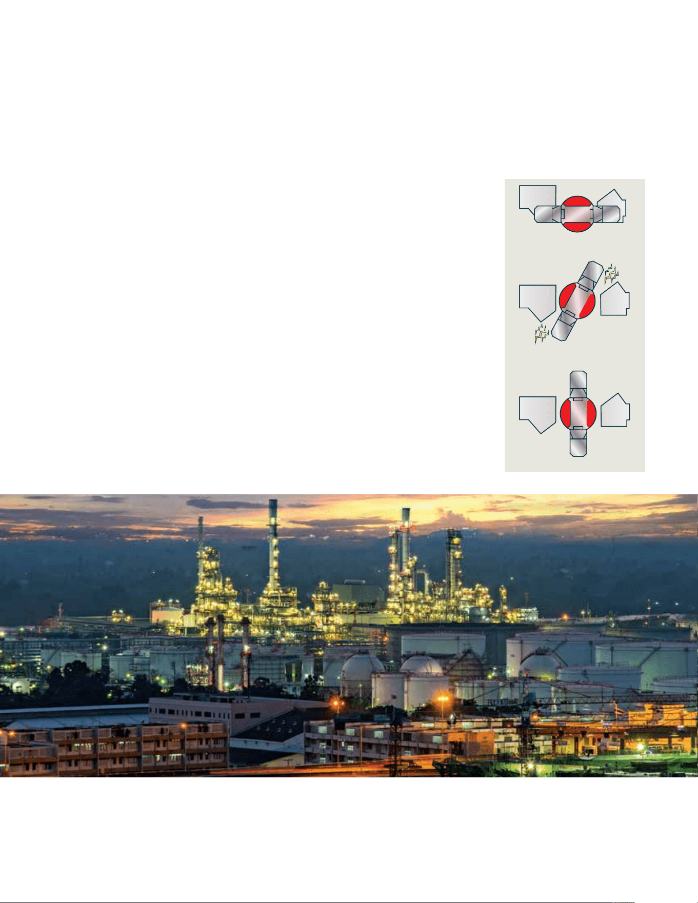
Like the time-proven Vacu-Break design,
the Siemens VBII double-break switching
action breaks the arc in two places. This
reduces heat generation and increases
switching speed by doubling the breaking
distance. The result is enhanced performance
and increased longevity. We also provide the
most visible blade design available today.
Unlike conventional knife blade switches,
the blades are self-aligning to ensure positive
contact. In addition, they have no wear and
friction point since the “electrical hinge”
has been eliminated. The result is a very
fast, positive and reliable switching action
for even the most severe applications.
One tough switch:
More rugged and durable in
demanding applications
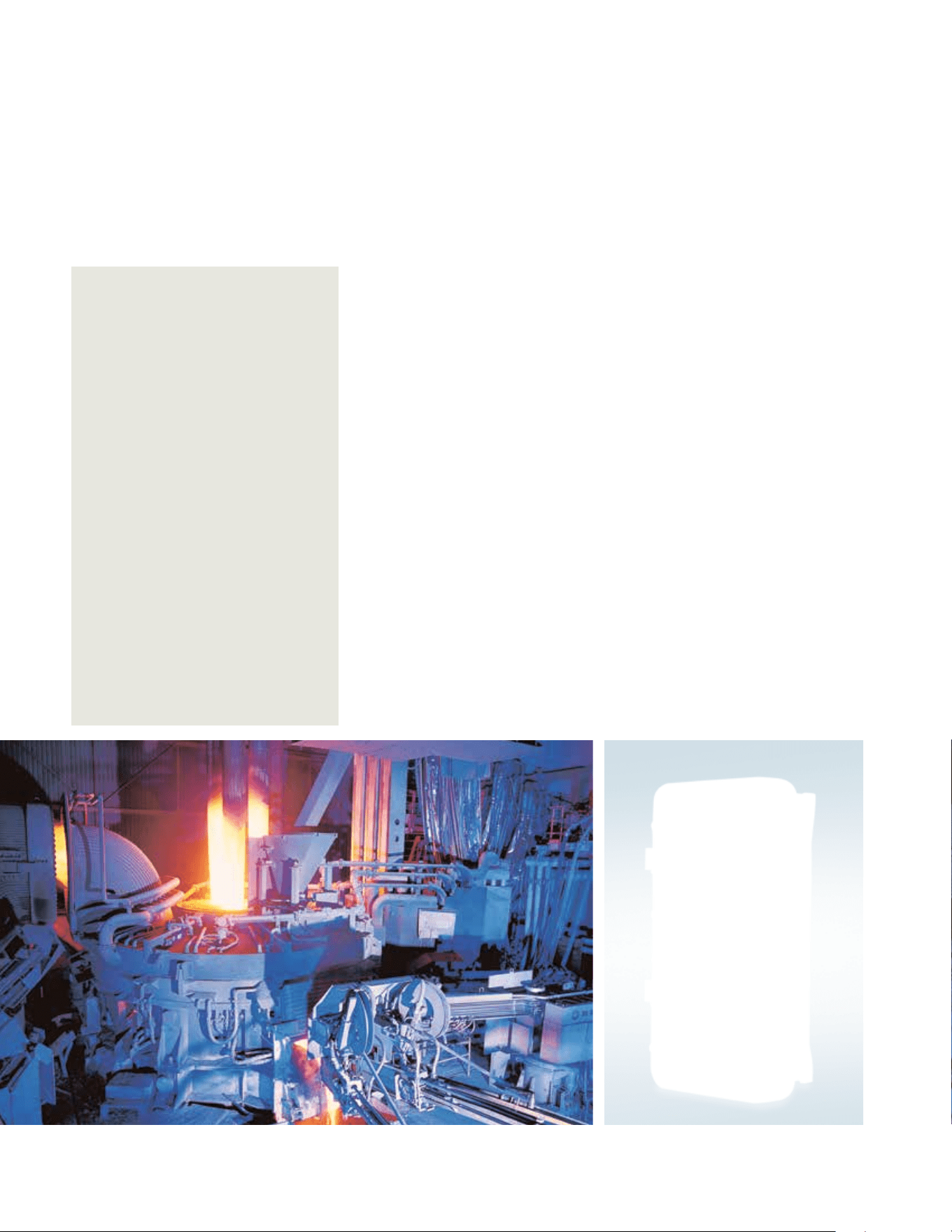
Siemens engineers tackled the problem of
designing a switch that would stand up under
the most demanding industrial conditions,
such as those in steel mills and mining
operations. These environments require a
switch that must work reliably and safely
in the midst of falling liquids, airborne
fibers, dust, metal particles, coolants and
other contaminants.
Tested and retested
All Siemens safety switches have been
tested not only to meet but to exceed
all UL requirements. These tests include
those for general purpose enclosed
switches and those designed for more
specialized purposes where applicable.
The result is a rugged, reliable design
that will provide superior performance
in a wide variety of applications.
Siemens now offers a complete line of enclosed switches featuring unique and innovative
designs that are unparalleled in the industry.
One tough switch:
Siemens Type VBII Safety Switch
closed
in operation
open

4 5
4 5
General and heavy duty features
Type VBII Safety Switch
Application
General duty switches
General Duty Switches are intended for applications where
reliable performance and continuity of service are needed,
but where duty requirements are not severe and usual
service conditions prevail. These switches are intended
for use primarily with supply circuits rated 240V AC or less
where the available fault current is less than 100,000Awhen
used with Class R or T fuses or 10,000A max. when used with
Class H fuses.
Application
Heavy duty switches
Heavy Duty Switches are intended for use in applications
where:
1. Rugged construction, reliable performance, continuity of
service and ease of maintenance are emphasized
2. Available fault currents higher than 10,000A are likely to
be encountered, such as in manufacturing plants, mass
production industries and commercial, institutional and
other large buildings served by network systems or
transformers of higher capacities
3. System voltage is 600V AC or DC max
4. A Type 12 or 4 / 4X enclosure is required
Short-circuit withstand ratings
General duty switches
Suitable for use on systems capable of delivering not more
than 100,000 RMS symmetrical amperes of fault current
when Class R fuses are installed. Also rated 100,000 AC max.
in 200-600A ratings with Class J and T fuses.
Short circuit withstand ratings
Heavy duty switches
Suitable for use on systems capable of delivering not
more than 200,000 RMS
1)
symmetrical amperes of fault
current when Class J or R fuses are installed except the
800 and 1200A switches, which are suitable for use on
circuits capable of delivering not more than 200,000 RMS
symmetrical amperes of fault current when Class L fuses
are installed. 100-1200A switches with Class T fuses and
field adapter kit are also 200,000 RMS symmetrical rated.
1)
100,000 RMS for 60 A compact non-fusible switches.
Fuses
General duty switches
Fusible switches will accept the following UL class fuses:
Class H
Class K
Class R—Class R fuse clip rejecter kits are required.
Class T—200-600A switches (200A switches require field
adapter kit)
Heavy duty switches
Fusible switches will accept the following UL class fuses:
Class H
Class K
Class R—Class R fuse clip rejecter kits are required
Class J—240 and 600V switches 600V switches are
field convertible
Class L—800 and 1200A switches only
Class T—100-1200A switches (100 and
200A switches require an adapter kit)
Cover interlocks
General duty switches
Defeatable cover interlocks on Type 1 switches and 60-600A
Type 3R switches prevent the switch door from being
opened when in the ON position.
Heavy duty switches
Defeatable dual cover interlocks are standard on all heavy
duty switches. Prevents cover from being opened when
switch is in the ON position and prevents switch from being
turned ON when door is opened.
Padlocks
General and heavy duty switches
Padlockable cover latch and multiple padlock provisions
on handle.
NEMA specifications
Meets NEMA standard KS-1-1990 for type GD and
HD switches.

4 5
4 5
Underwriters’ Laboratories Inc.
Listed by UL under file #E4776 as
enclosed switches and also suitable
for use as service equipment except
on1200A switches on Y systems of
more than 150V to ground.
Meets UL98 standard for enclosed
switches and enclosures.
Type 1 switches—general purpose
enclosures (Type 1)
Type 3R switches—rainproof enclosures
(Type 3R)
Type 4/4X switches—special purpose
enclosures (Type 4/4X)
Type 12 switches—special purpose
enclosures (Type 12).
Groundable neutrals
General and Heavy Duty Switches
are designed for use on systems
requiring neutrals to have groundable
neutral blocks.
Feature comparison
General
duty
Heavy
duty
Double
throw Features / Ratings
30-600 Amps
800 and 1200 Amps
240 Volts AC
600 Volts AC
250 Volts DC
600 Volts DC
Double-break visible blade design (30-200A)
Quick-make, quick-break switching action
Highly visible ON/OFF handle indication
Handle design for hook stick operation
Padlockable cover latch
Padlockable handle
3)
Single voidable cover interlock
Dual voidable cover interlock
Type 1 enclosure
Type 3R enclosure
Type 12 enclosure
Type 4/4X enclosure
Generous wiring gutters that meet UL and NEC wire-bending
space requirements
Lugs suitable for copper or aluminum at 60˚C or 75˚C
CU/AL wire lugs that meet UL 486B requirements
Suitable for field-convertible compression connectors
6)
All plated copper current carrying parts (except lugs)
Spring reinforced Fuse Clips (except 30A general duty)
Clear pivoting line terminal shield
Replacement parts
Field addable 200% neutral
7)
7)
1)
Provisions for UL Class T, R and H fuses
1)
Provisions for UL Class J and L fuses
Metal nameplate
Aux. switch kit
4)
Type 4X with stainless steel interior parts
5)
Rolled flange enclosure design (30-200A)
UL approved HP ratings for high efficiency motors
Isolated ground kits
1)
400 & 600A fusible, double-throw switches accept only Class J or T fuses.
2)
30A general duty switches have fuse clips constructed of spring type copper.
3)
Not supplied on 30A outdoor & plug fuse switches.
4)
30-200A Type VBII in stainless steel enclosures.
5)
60-200A
6)
200A general duty switches have aluminum neutral assemblies.
7)
100-600A GD and 100-1200A HD switches will accept Class T fuses.

6 7
Type 1 enclosure
Type 1 enclosures are intended for indoor use primarily to provide protection
against contact with the enclosed equipment in locations where unusual service
conditions do not exist.
Features
Tangential knockouts in all
box surfaces (30-600A HD and
60-600 GD)
Two- and three-point mounting
with top keyhole
Door that opens greater than 180º
Formed flange enclosure edges
180º plus side opening door
Drawn cover design
for increased durability and
resistance to damage (30-600A)
Rugged metal handle with a red
insulating grip
Front operable cover interlock
release with positive rotating
release action (30-1200A
heavy duty and 60-600A
general duty)
Metal nameplates on all hevy
duty switches

6 7
Type 3R enclosure
Type 3R enclosures are intended for outdoor use primarily to provide a degree
of protection against falling rain and sleet, and must remain undamaged by the
formation of ice on the enclosure. They are not intended to provide protection
against conditions such as dust, internal condensation or internal icing.
Features
Tangential knockouts in all
box surfaces below lowest
live parts (30-600A)
Two- and three-point mounting
with top keyhole
Formed flange enclosure edges
Formed flange enclosure edges
180º plus side opening door
Double overlap enclosure door
top to provide superior
protection against entry of rain
Type HA hub provision
30A general duty
release action (30-1200A
Type HS hub provision
(30-200A switches)
Galvanized steel construction
Drawn cover design for
increased durability and
resistance to damage (30-200A)
Rugged metal handle with a red
insulating grip
Front operable cover interlock
release with positive rotating
release action (30-1200A
heavy duty and 60-600A
general duty)
Metal nameplates on all heavy

8 9
Type 4/4X enclosure
Type 4/4X enclosures are intended for indoor or outdoor use primarily to provide
a degree of protection against windblown dust, rain, splashing water and hose-
directed water. They are not intended to provide protection against conditions
such as internal condensation or internal icing. Also meets 4X definition by
providing a high degree of protection against corrosion.
Features (Standard 4X)
Ground lugs installed as standard
External mounting feet with two-,
three- and four-point mounting
Formed front gasket flange with
continuously welded seams
Heavy duty front opening low-
profile stainless steel latches
Stainless steel enclosure
Stainless steel interior parts on
30-200A switches
Formed out enclosure flanges that
prevent liquid entry when door
is open
Rugged hinge design
180º-plus opening door
Rugged metal handle with a red
insulating grip
Front operable cover interlock
release with positive rotating
release action (30-1200A
heavy duty)
Stainless steel nameplate
Features (Non-Metallic 4X)
External mounting
Ground lug installed as standard
Fiberglass reinforced polyester
enclosure
No external metal parts
Removable door for easy wiring
Front operable cover interlock
release with positive rotating
release action

8 9
Type 3R/12 enclosure
Type 3R / 3S enclosures are intended to provide a degree of protection against
windblown dust, and to allow operation when ice-laden. They are not intended
to provide protection against conditions such as condensation or internal icing.
Type 12 enclosures are intended for indoor use primarily to provide a degree of
protection against dust, falling dirt and dripping water. They are not intended to
provide protection against conditions such as internal Command.
Features
External mounting feet with two,
three and four-point mounting
Formed front gasket flange
Unique heavy duty front opening
low-profile latches
Galvanized steel enclosure
Formed out enclosure flanges that
provide an added degree of
protection against entry of dust
Rugged hinge design
180º-plus opening door
3R / 3S / 12 rating as standard
allows outdoor use
Rugged metal handle with a red
insulating grip
Front operable cover interlock
release with positive rotating
release action (30-1200A
heavy duty)
Metal nameplates on
Type 3S / 12 enclosures
10 11
Type 7 enclosures are intended for indoor use in locations classified as Class I,
Groups A, B, C or D as defined in the National Electrical Code.
Type 9 enclosures are intended for indoor use in locations classified as
Class II, Groups E, F or G as defined in the National Electrical Code.
Type 7 and 9 enclosure
Features
Molded case switch available
in 30-600A ratings
Cast aluminum enclosure
External door clamps
External mounting feet
Metal nameplate
10 11
Features
Compact size
Visible blade, double-break
switching action
Quick-make, quick-break
operating mechanism
Highly visible ON/OFF indicators
Padlock-off handle feature
Door padlock provision
Bondable neutral (where indicated)
Lugs suitable for copper or
aluminum wire
30A cartridge fuse switches rated
100,000 AC with Class R fuses
General duty switches
Plug fuse and special application types
Ampere
rating
Indoor - Type 1 Outdoor - Type 3R Horsepower rating
6)
Catalog
number
Ship.
wgt.*
1)
Dwg.
fig.
Catalog
number
Ship.
wgt.*
1)
Dwg.
fig.
1-Phase, 2-Wire
Std. Max
120/240 Volt Fusible (Plug Fuse Type) 10,000 AIC Max
1-Pole and Solid Neutral 120 Volt – 1-Phase, 2-Wire
30 LF111N 31 1 LF111NR 35 12
Z\x
2
2-Pole and No Neutral 120/240V – 1-Phase, 2-Wire
30 — — — Use 2-Pole and solid neutral
2-Pole and Solid Neutral 120/240V – 1-Phase, 2-Wire
30 LF211N 37 1 LF211NR 35 12
1 Z\x
3
240 Volt Non-Fusible (Special Application)
2-Pole 240 Volt – 1- or 2-Pole – No Fuse 240 Volt – 1-Phase, 2-Wire
60 — — —
LNF222R
2)
35
12
2)
— 10
Selection Information – Fused/Non-fused pullouts
2)
Ampere
rating
Number
of poles
Number
of blades
Number
of fuses
Catalog
number
Shipping
weight*
Dimensions (inches)
Height Width Depth
Fused Pullout – 1-Phase, 2-Wire
3)
10,000 AIC Max 240 Volts AC
30
7)
60
4)
2
2
2
2
2
2
WF2030
WF2060
21
8)
5
9 Z\,
9 Z\,
5 B\cx
5 B\cx
3 M\zn
3 M\zn
Non-Fused Pullout – 1-Phase, 2-Wire
4)
240 Volts AC
60 2 2 — WN2060
15
8)
7 C\, 5 B\cx 3 M\zn
* In pounds (lbs).
1)
Package of 10.
2)
No hub provision with this switch.
3)
Fuses – not included.
4)
Max. horsepower rating – 10.
5)
Features apply to 30A General Duty and Plug Fuse Type Switches.
6)
Dual horsepower ratings:
Std.– applies when non-time delay fuses are installed.
Max.– applies when time-delay fuses are installed.
7)
Max. horsepower rating – 3.
8)
Package of 6.

12 13
General duty switches(60-600A)
Features
1. Cover interlock
2. Tangential knockouts through
600A for easy conduit lineup
3. Quick-make, quick-break operating
mechanism that ensures
positive operation
4. Provisions for T, R, J, H and
K class fuses (T & J 200-600A)
5. Generous wiring gutters that
meet or exceed NEC wirebending
space requirements
6. Visible blade, double-break
switch action
7. Positive two- or three-point
mounting
8. Highly visible red handle grip
9. Informative door labeling
which includes replacement
parts list
10. Handle and cover
padlocking provisions
11. Side-hinged door that opens
180 degrees for easier wiring
12. A unique enclosure design that
adds rigidity and strength. Its
rolled edge prevents cuts and
scrapes to conductors and to
installers’ hands
2
7
4
8
1
6
3
5
J
9
L
K
12 13
General duty switches
System
Ampere
rating
Indoor – Type 1 Outdoor – Type 3R
Dwg.
fig
Horsepower ratings
1)
240V AC
250
volt
DC
Catalog
number
Ship.
wgt. (lbs)
Std. pkg.
Dwg.
fig
Catalog
number
Ship.
wgt. (lbs)
Std. pkg.
1-Phase,
2-Wire
2-Phase,
4-Wire
3-Phase,
3-Wire
Std. Max. Std. Max. Std. Max. Std.
240 Volt Fusible
2-Pole, 2-Fuse, and Solid Neutral
2)
3)
4)
240 Volt AC/250 Volt DC
30
60
100
200
GF221N
GF222N
GF223N
GF224N
35
7)
14
23
47
1
4
6
7
GF221NR
5)
GF222NR
GF223NR
GF224NR
35
7)
14
23
48
12
15
17
18
1
1
/
2
3
7
1
/
2
15
3
10
15
—
—
—
—
—
—
—
—
—
3
7
1
/
2
15
25
7
1
/
2
15
30
60
5
10
20
40
3-Pole, 3-Fuse, and Solid Neutral
4)
240 Volt AC/250 Volt DC
30
60
100
200
400
600
GF321N
GF322N
GF323N
GF324N
GF325NA
GF326NA
24
6)
15
25
49
94.6
95.6
2
4
7
7
9
9
GF321NR
5)
GF322NR
GF323NR
GF324NR
GF325NRA
GF326NRA
24
6)
15
25
50
94.6
95.6
13
15
17
18
20
20
1
1
/
2
3
7
1
/
2
15
15
15
3
10
15
—
—
—
—
—
—
—
—
—
—
—
—
—
—
—
3
7
1/
2
15
25
50
75
7
1
/
2
15
30
60
125
200
5
10
20
40
50
—
240 Volt Non-Fusible
3)
4)
2-Pole or 3-Pole 240 Volt AC/250 Volt DC
30
60
100
200
GNF321
GNF322
GNF323
GNF324
24
6)
12
23
46
2
3
6
7
GNF321R
5)
GNF322R
GNF323R
GNF324R
24
6)
13
24
47
13
14
17
18
—
—
—
—
3
10
15
15
—
—
—
—
—
—
—
—
7
1
/
2
15
30
60
—
—
—
—
5
10
20
40
400
600
GNF325
GNF326
114
116
8
8
Use 600V Switch — HNF365RA
Use 600V Switch — HNF366RA
—
—
15
15
—
—
—
—
125
200
—
—
50
—
1)
Dual horsepower ratings: Std.- applies when
non-time delay fuses are installed. Max.- applies
when time-delay fuses are installed.
2)
These switches are UL-listed for application on
grounded B-phase systems.
3)
Suitable for use on 3-phase motor loads.
4)
Service entrance labeled.
5)
Has provision for ECHA type hub.
6)
5 switches per standard package.
7)
10 switches per standard package.

14 15
Heavy duty switches
Features
1. Quick-make, quick-break operating
mechanism that ensures positive operation
2. Visible blade, double-break switching
action
3. Arc chutes dissipate heat and prolong
switch life
4. Highly visible red handle grip designed for
hook stick operation
5. Defeatable dual cover interlock
6. Center punch provided for field drilling to
allow ON padlocking
7. Handle can be padlocked in the OFF
position with up to three padlocks with
5/16” hasps
8. Generous top, bottom and side gutters
that meet or exceed NEC wire-bending
space requirements
9. Informative door labeling, which includes
replacement parts list
10. Tangential knockouts through 600A for
easy conduit lineup
11. Side-hinged door that opens past 180
degrees for easier wiring
12. Unique enclosure design increases
rigidity and prevents cuts and scrapes to
conductors and installers’ hands
13. Spring reinforced fuse clips that assure
reliable contact for cool operation
14. Door latch securely holds door closed and
allows cover padlocking
15. Front removable mechanical lugs that
are suitable for CU/AI 60˚C or
75˚Cconductors
16. Lugs are field convertible to copper body
and to a wide variety of compression
connectors
17. Hinged clear line terminal shield with
probe holes for inspecting or testing line
side terminals
18. Embossed aluminum nameplate on Heavy
Duty Switches provides highly visible
ON/OFF indication
19. Drawn cover for increased rigidity and
resistance to abuse
20. Top key hole and bottom mounting holes
provide easy two- or three-point mounting
2
O
3
R
4
6
7
J
11
9
19
14 15
20
8
12
1
5
14
17
16
13
16 17
Heavy duty switches
n
Built to order. Allow 3-5 weeks for delivery.
1)
Dual horsepower ratings: Std.- applies when
non-time delay fuses are installed. Max. - applies
when time-delay fuses are installed.
2)
These switches are UL-listed for application on
grounded B-phase systems and are suitable for
3-phase motor applications.
3)
When a neutral is required use a field installed
neutral kit.
4)
Suitable for use as service entrance equipment.
5)
Also rated Type 3S/3R.
6)
304 grade stainless steel.
System
Ampere
rating
Indoor – Type 1 Outdoor – Type 3R
Dwg.
fig
Horsepower rating
1)
240V AC
250
volt
DC
Catalog
number
Ship wt.
(lbs.)
Std. pkg
Dwg.
fig
Catalog
number
Ship wt.
(lbs.)
Std. pkg
1-Phase,
2-Wire
2-Phase,
4-Wire
3-Phase,
3-Wire
Std. Max. Std. Max. Std. Max. Std.
240 Volt Fusible
4)
2-Pole, 2-Fuse, and Solid Neutral
2)
(Also used for 2-Pole, 2-Wire Applications) 240 Volt AC/250 Volt DC
30
60
100
200
400
600
800
1200
HF221N
HF222N
HF223N
HF224N
HF225NA
HF226NA
HF227N
HF228N
n
12
18
23
47
91.1
95.6
365
385
4
5
6
7
9
9
11
11
HF221NR
HF222NR
HF223NR
HF224NR
HF225NRA
HF226NRA
HF227NR
HF228NR
n
13
19
24
48
91.1
95.6
365
385
15
16
17
18
20
20
22
22
1
1
/
2
3
7
1
/
2
15
15
15
—
—
3
10
15
—
—
—
—
—
—
—
—
—
—
—
—
—
—
—
—
—
—
—
—
—
3
7
1
/
2
15
25
50
75
100
100
7
1
/
2
15
30
60
125
200
250
250
5
10
20
40
50
50
50
50
3-Pole, 3-Fuse, and Solid Neutral
(Also used for 3-Pole, 3-Wire Applications) 240 Volt AC/250 Volt DC
30
60
100
200
400
600
800
1200
HF321N
HF322N
HF323N
HF324N
HF325NA
HF326NA
HF327N
HF328N
14
19
25
49
94.6
99.6
375
395
4
5
6
7
9
9
11
11
HF321NR
HF322NR
HF323NR
HF324NR
HF325NRA
HF326NRA
HF327NR
HF328NR
15
20
26
50
94.6
99.6
375
388
15
15
17
18
20
20
22
22
1
1
/
2
3
7
1
/
2
15
15
15
—
—
3
10
15
—
—
—
—
—
—
—
—
—
—
—
—
—
—
—
—
—
—
—
—
—
3
7
1
/
2
15
25
50
75
100
100
7
1
/
2
15
30
60
125
200
250
250
5
10
20
40
50
50
50
50
240 Volt Fusible
4)
2-Pole, 2-Fuse
3)
240 Volt AC/250 Volt DC
Type 4/4X Stainless
6)
Type 12 Industrial
5)
30
60
100
200
HF221S
HF222S
HF223S
HF224S
13
19
24
48
24
25
26
27
HF221J
HF222J
HF223J
HF224J
13
19
24
48
24
25
26
27
1
1
/
2
3
7
1
/
2
15
3
10
15
—
—
—
—
—
—
—
—
—
3
7
1
/
2
15
25
7
1
/
2
15
30
60
5
10
20
40
3-Pole, 3-Fuse
3)
(Also used for 2-Pole, 2-Wire Applications in 400–800A Ratings) 240 Volt AC/250 Volt DC
30
60
100
200
400
600
800
HF321S
HF322S
HF323S
HF324S
HF325SA
HF326SA
HF327S
n
14
20
25
49
93
98
370
24
25
26
27
30
30
33
HF321J
HF322J
HF323J
HF324J
HF325JA
HF326JA
HF327J
n
14
20
25
49
93
98
365
24
25
26
27
31
31
33
1
1
/
2
3
7
1
/
2
15
15
15
—
3
10
15
—
—
—
—
—
—
—
—
—
—
—
—
—
—
—
—
—
—
3
7
1
/
2
15
25
50
75
100
7
1
/
2
15
30
60
125
200
250
—
10
20
40
50
50
50
16 17
Heavy duty switches
n
Built to order. Allow 3-5 weeks for delivery.
1)
60-600A 3-Pole switches are also rated 600V DC.
2)
Height reduced switch (45.25 rather than 56 inches
in height) for use with 500MCM or smaller conductors.
3)
Use 3-Pole switch for 200A applications.
4)
Dual horsepower ratings: Std.- applies when non-time
delay fuses are installed. Max.- applies when time-delay
fuses are installed.
5)
Suitable for use as service entrance equipment except on
1200 Amp solidly grounded wye systems per NEC 230.95.
6)
Also rated Type 3S/3R.
7)
Indicates oversized enclosure (30A switch with 60A
lugs in a 60A enclosure or 60A switch with 100A lugs
in a 100A enclosure).
8)
600V DC & 600V DC horsepower rating shown
requires (2) poles to be connected in series.
9)
304 grade stainless steel.
Systems
Ampere
rating
Indoor – Type 1 Outdoor – Type 3R
Dwg.
Fig
Horsepower rating
4)
480V AC 600V AC
250
volt
DC
600
volt
DC
Catalog
number
Ship
wt.
(lbs.)
Std. pkg
Dwg.
fig
Catalog
number
Ship wt.
(lbs.)
Std. pkg
1-Phase,
2-Wire
3-Phase,
3-Wire
1-Phase,
2-Wire
3-Phase,
3-Wire
Std. Max. Std. Max. Std. Max. Std. Max.
600 Volt Fusible
5)
2-Pole, 2-Fuse
3)
480 Volt AC/600 Volt AC/600 Volt DC
30
60
100
HF261
HF262
HF263
15
20
26
4
5
6
HF261R
HF262R
HF263R
15
20
27
15
16
17
3
5
10
7
1
/
2
20
30
—
—
—
—
—
—
3
10
15
10
25
40
—
—
—
—
—
—
5
10
20
15
30
50
3-Pole, 3-Fuse
480 Volt AC/600 Volt AC/250 Volt DC
1)
30
30
60
60
100
200
400
600
800
1200
HF361
HF361L
7)
HF362
—
HF363
HF364
HF365A
1)
HF366A
1)
HF367
HF368
14
19
19
—
24
48
93
98
365
366
4
5
5
—
6
7
9
9
11
11
HF361R
HF361RL
7)
HF362R
HF362RL
7)
HF363R
HF364R
HF365RA
1)
HF366RA
1)
HF367R
HF368R
15
20
20
25
25
49
157
161
365
385
15
16
16
17
17
18
20
20
22
22
3
3
5
5
5
25
—
—
—
—
7
1
/
2
7
1
/
2
20
20
20
50
—
—
—
—
5
5
15
15
25
50
100
150
200
200
15
15
30
30
60
125
250
400
500
500
3
3
10
10
15
30
—
—
—
—
10
10
25
25
4 0
5 0
—
—
—
—
7
1
/
2
7
1
/
2
15
1
5
3
0
6
0
125
200
250
250
20
20
50
50
75
150
350
500
500
500
5
5
10
10
20
40
50
50
50
50
—
—
30
8)
30
8)
50
8)
50
—
—
—
—
3-Pole, 3-Fuse and Solid Neutral 480 Volt AC/600 Volt AC/600 Volt DC
1)
30
60
100
200
400
600
800
1200
HF361N
HF362N
HF363N
HF364N
HF365NA
HF366NA
HF367N
HF368N
14
19
25
49
9
4.6
99.6
375
395
4
5
6
7
9
9
11
11
HF361NR
HF362NR
HF363NR
HF364NR
HF365NRA
HF366NRA
HF375NR
HF368NR
15
20
26
50
9
4.6
99.6
374
388
15
16
17
18
20
20
22
22
3
5
10
25
—
—
—
—
7
1
/
2
20
30
50
—
—
—
—
5
15
25
50
—
—
—
—
1
5
30
60
125
250
400
500
500
3
10
15
30
—
—
—
—
10
25
40
50
—
—
—
—
7
1
/
2
15
30
60
125
200
250
250
20
50
75
150
350
500
500
500
5
10
20
40
50
50
50
50
—
30
8)
50
8)
50
—
—
—
—
600 Volt Fusible
5)
(For 2-Pole Applications use outside poles of 3-Pole Switches)
2-Pole, 2-Fuse
3)
480 Volt AC/600 Volt AC/600 Volt DC
Type 4/4X Stainless
9)
Type 12 Industrial
6)
30
60
100
HF261S
HF262S
HF263S
n
16
20
27
24
25
26
HF261J
n
HF262Jn
HF263Jn
15
20
27
24
25
26
3
5
10
7
1
/
2
20
30
—
—
—
—
—
—
3
10
20
10
25
40
—
—
—
—
—
—
5
10
20
15
30
50
3-Pole, 3-Fuse 480 Volt AC/600 Volt AC/250 Volt DC
1)
30
60
100
200
400
600
800
1200
HF361S
HF362S
HF363S
HF364S
HF365SA
1)
HF366SA
1)
HF367S
HF368S
n
13
20
25
49
93
98
370
388
24
25
26
27
30
30
33
—
HF361J
HF362J
HF363J
HF364J
HF365JA
1)
HF366JA
1)
HF367J n
HF368Jn
14
20
25
49
93
98
365
388
24
25
26
27
31
31
33
33
—
—
—
—
—
—
—
—
—
—
—
—
—
—
—
—
5
1
5
25
50
100
150
200
250
15
30
60
125
250
400
500
500
—
—
—
—
—
—
—
—
—
—
—
—
—
—
—
—
7
1
/
2
15
30
60
125
200
250
250
20
50
75
150
350
500
500
500
5
10
20
40
50
50
50
50
—
30
8)
50
8)
50
—
—
—
—
n
Built to order. Allow 3-5 weeks for delivery.
1)
60-600A 3-Pole switches are also rated 600V DC.
2)
Compact switch (11.1"H, 6.6"W box less cover and
handle). Short circuit withstand rating—100,000 RMS
sym. amps.
3)
Use 3-Pole switch for 200A application.
4)
Suitable for use as service entrance equipment except
for 1200 when used on a 480 or 600V grounded
wye system.
5)
Also rated type 3S / 3R.
6)
Indicates oversized enclosure (30A switch in a 60A
enclosure or a 60A switch in a 100A enclosure).
7)
600V DC and 600V DC horsepower rating shown
requires (2) poles to be connected in series.
8)
304 grade stainless steel. For switches with
enclosures constructed from 316 grade stainless steel,
see page 4-16 of Speed Fax.
System
Ampere
rating
Indoor – Type 1 Outdoor – Type 3R
Dwg.
fig
Horsepower rating
240V AC 480 Volt 600 Volt
250V
DC
600V
DC
Catalog
number
Ship wt.
(lbs.)
Dwg.
fig
Catalog
number
Ship wt.
(lbs.) 1-Phase 3-Phase 1-Phase 3-Phase 1-Phase 3-Phase
600 Volt Non-Fusible
4)
2-Pole
3)
480 Volt AC / 600 Volt AC / 600 Volt DC
30
60
100
HNF261
HNF262
HNF263
12
19
24
3
5
6
HNF261R
HNF262R
HNF263R
13
20
25
14
16
17
—
—
—
—
—
—
7
1
/
2
20
25
—
—
—
10
25
40
—
—
—
5
10
20
15
30
50
3-Pole
480 Volt AC / 600 Volt AC / 600 Volt DC
30
30
60
60
60
100
200
400
600
800
1200
HNF361
—
HNF362H
2)
HNF362
1)
—
HNF363
1)
HNF364
1)
HNF365A
1)
HNF366A
1)
HNF367
HNF368
12
—
11
18
—
23
46
75
77
295
305
3
—
3
5
—
6
7
8
8
10
10
HNF361R
HNF361RL
6)
HNF362RH
2)
HNF362R
1)
HNF362RL
6)
HNF363R
1)
HNF364R
1)
HNF365RA
1)
HNF366RA
1)
HNF367R
HNF368R
13
19
11
19
24
24
47
75
77
295
307
14
16
14
16
17
17
18
19
19
21
21
5
5
10
10
10
15
15
15
15
15
15
10
10
20
20
20
40
60
125
200
250
250
7
1
/
2
7
1
/
2
20
20
20
30
50
50
50
50
50
20
20
50
50
50
75
125
250
400
500
500
10
10
20
25
25
40
50
50
50
50
50
30
30
40
60
60
100
150
350
500
500
500
5
5
10
10
10
20
40
50
50
50
50
—
—
—
30
7)
30
7)
50
7)
50
—
—
—
—
600 Volt Non-Fusible
4)
2-Pole
3)
480 Volt AC / 600 Volt AC / 600 Volt DC
Type 4/4X Stainless
8)
Type 12 Industrial
5)
30
60
100
HNF261S
HNF262S
HNF263S
n
13
20
25
3
5
6
HNF261J
HNF262J
HNF263J
n
13
20
25
23
25
26
—
—
—
—
—
—
7
1
/
2
20
30
—
—
—
10
25
40
—
—
—
5
10
20
15
30
50
3-Pole
480 Volt AC / 600 Volt AC / 250 Volt DC
30
60
60
100
200
400
600
800
1200
HNF361S
HNF362SH
2)
HNF362S
1)
HNF363S
1)
HNF364S
1)
HNF365SA
1)
HNF366SA
1)
HNF367S
HNF368S
n
13
15
19
24
47
75
77
295
310
23
23
25
26
27
28
28
32
—
HNF361J
HNF362JH
2)
HNF362J
1)
HNF363J
1)
HNF364J
1)
HNF365JA
1)
HNF366JA
1)
HNF367Jn
HNF368Jn
13
14
19
24
47
75
77
295
310
23
23
25
26
27
29
29
32
32
5
10
10
15
15
15
15
15
15
10
20
20
40
60
125
200
250
250
7
1
/
2
20
30
40
50
50
50
50
50
20
50
50
75
125
250
400
500
500
10
20
25
40
50
50
50
50
50
30
40
60
100
150
350
500
500
500
5
10
10
20
40
50
50
50
50
—
—
30
7)
50
7)
50
—
—
—
—
18 19
Heavy duty switches
3-Pole, 3-Wire Fusible, Type 3R
4)
600 Volt AC / 250 Volt DC
1)
30
60
HF361RW
HF362RW
17
22
3
10
7
1
⁄2
15
15
30
20
50
5
10
—
30
5)
3-Pole, 3-Wire Non-Fusible, Type 3R
4)
600 Volt AC / 250 Volt DC
1)
30
60
HNF361RW
HNF362RW
14
21
3
10
10
20
20
50
30
60
5
10
—
30
5)
3-Pole, 3-Wire Fusible, Type 12
3) 4)
600 Volt AC / 250 Volt DC
1)
30
60
100
200
400
600
HF361JW
HF362JW
HF363JW
HF364JW
HF365JWA
HF366JWA
17
22
26
53
93
98
3
10
15
—
—
—
7
1
⁄2
15
30
60
125
200
15
30
60
125
250
400
20
50
75
150
350
500
5
10
20
40
50
50
—
30
5)
50
5)
50
—
—
3-Pole, 3-Wire Non-Fusible, Type 12
3) 4)
600 Volt AC / 250 Volt DC
1)
30
60
100
200
400
HNF361JW
HNF362JW
HNF363JW
HNF364JW
HNF365JWA
14
21
25
51
75
3
10
15
15
15
10
20
40
60
125
20
50
75
125
250
30
60
100
150
350
5
10
20
40
50
—
30
5)
50
5)
50
—
3-Pole, 3-Wire Fusible, Type 4X Stainless Steel
4) 6)
600 Volt AC / 250 Volt DC
1)
30
60
100
200
400
HF361SW
HF362SW
HF363SW
HF364SW
HF365SWA
17
23
28
55
75
3
10
15
—
15
7
1
⁄2
15
30
60
125
15
30
60
125
250
20
50
75
150
350
5
10
20
40
50
—
30
5)
50
5)
50
—
3-Pole, 3-Wire Non-Fusible, Type 4X Stainless Steel
4) 6)
600 Volt AC / 250 Volt DC
1)
30
60
100
200
400
HNF361SW
HNF362SW
HNF363SW
HNF364SW
HNF365SWA
15
23
27
54
75
3
10
15
15
15
10
20
40
60
125
20
50
75
125
250
30
60
100
150
350
5
10
20
40
50
—
30
5)
50
5)
50
—
System
Ampere
rating Catalog number
Ship
Wt. (lbs.)
Maximum horsepower rating
2)
240V AC 480V AC 600V AC
250V
DC
600V
DC1-Phase, 2-Wire 3-Phase, 3-Wire 3-Phase, 3-Wire 3-Phase, 3-Wire
18 19
Heavy duty switches
Type 4/4X & 12 with viewing window
Description
30–600A, 3-pole 600V max. in fusible and non-fusible versions in Type 4/4X
stainless steel and Type 12 enclosures. All allow viewing of visible blade position.
30–200A also allow viewing of indicating type fuses.
Features
Rugged installer-friendly enclosure
design features a gasket flange with
continuously welded seams
Tool-free cover latches
Two, three and four point mounting
Metal handle with large insulating
grip features a positive stop in both
ON and OFF position
Ground lugs provided as standard
Type 12 enclosures are fabricated
from galvanized steel and are also
rated for 3R/3S outdoor applications
Type 4X stainless steel switches
(30–200A) are provided with
stainless steel interior parts
The widest range of accessories
available including 200% neutrals,
gold plated PLC auxiliary contacts
and isolated ground kits
1)
200A switches are also rated 600V DC.
2)
Maximum HP ratings listed apply only when time
delay fuses are used.
3)
Also rated 3S/3R for outdoor use.
4)
All switches are suitable for use as service entrance
equipment. Use outside poles of 3-pole switch for
2-pole application.
5)
600V DC and 600V DC horsepower rating shown
requires (2) poles to be connected in series.
6)
304 grade stainless steel. For switches with
enclosures constructed from 316 grade stainless
steel,
see page 4-16 of Speed Fax.
20 21
Application
Receptacle Safety Switches provide cord connection protection of heavy-duty
portable equipment (welders, infrared ovens, batch feeders, portable conveyors,
assembly line fixtures and tools, refrigerator trucks, etc.) under load or fault
conditions. All receptacle switches are supplied with 4 prong receptacles. (3
phase, 3W plus ground)
Description
1 2
Type 12 and 4/4X Receptacle Safety Switches are available with 3-phase, 4-wire
grounded type Crouse-Hinds Arktite™ 2 or Pyle-National prewired and mounted
receptacles with interlock linkage to the switch mechanism. Insertion or removal
of the plug is prevented by the interlock linkage while the switch is in the ON
position. Receptacle prevents operation of switch if incorrect plug is inserted.
Heavy duty
Special application / Interlocked receptacle switches
Crouse-Hinds interlocked receptacle switches
Ampere
rating
5)
Type 12
6)
Catalog
number
Type 4/4X
7)
Catalog
number
Shipping
weight
Std. pkg.
4)
Accepts Crouse-Hinds
Arktite
1)
plug
Catalog number
240V Fusible, 3-Pole, 3-Wire
30
60
100
HF321JCH
HF322JCH
HF323JCH
HF321SCH
HF322SCH
HF323SCH
23
30
36
APJ3485 & NPJ3485
APJ6485 & NPJ6485
APJ10487 & NPJ10487
600V Fusible, 3-Pole, 3-Wire
30
60
100
HF361JCH
HF362JCH
HF363JCH
HF361SCH
HF362SCH
HF363SCH
24
30
36
APJ3485 & NPJ3485
APJ6485 & NPJ6485
APJ10487 & NPJ10487
600V Non-Fusible, 3-Pole, 3-Wire
30
60
100
HNF361JCH
HNF362JCH
HNF363JCH
HNF361SCH
HNF362SCH
HNF363SCH
22
29
35
APJ3485 & NPJ3485
APJ6485 & NPJ6485
APJ10487 & NPJ10487
600V Fusible, 3-Pole, 3-Wire with viewing window
30
60
100
HF361JCHW
HF362JCHW
HF363JCHW
HF361SCHW
HF362SCHW
HF363SCHW
24
30
36
APJ3485 & NPJ3485
APJ6485 & NPJ6485
APJ10487 & NPJ10487
600V Non-Fusible, 3-Pole, 3-Wire with viewing window
30
60
100
HNF361JCHW
HNF362JCHW
HNF363JCHW
HNF361SCHW
HNF362SCHW
HNF363SCHW
22
29
35
APJ3485 & NPJ3485
APJ6485 & NPJ6485
APJ10487 & NPJ10487
Pyle-National interlocked receptacle switches
3 Poles fusible and non-fusible
Ampere rating
Voltage
rating
Type 12
Catalog
number
Type 12
7)
Stainless Steel
Catalog
number
Shipping
weight
Std. pkg.
Accepts Pyle-National
QuelArc™
2)
3)
plugs
Switch Recept. Plug catalog number
30 30
600 (F)
600 (N-F)
HF361JPN
HNF361JPN
HF361SPN
HNF361SPN
23
21
JPD-83046
60 60
240 (F)
600 (F)
600 (N-F)
HF322JPN
HF362JPN
HNF362JPN
—
HF362SPN
HNF362SPN
28
28
27
JPD-116046
1)
Arktite™ is a registered trademark of the Crouse-Hinds Company. Plugs are not sold or supplied by Siemens.
2)
Indicates plug with maximum diameter cable bushing.
3)
QuelArc™ is a registered trademark of the Pyle-National Company.
4)
In pounds (lb).
5)
Ampere rating of both switch and receptacle.
6)
Also rated Type 3R/3S
7)
Enclosure is constructed of Type 304 stainless steel.
20 21
Application
4 & 6 pole switches are commonly used as a disconnecting means for two
speed, two-winding motors. Fused switches provide both over current and
short-circuit protection. Non-fusible switches normally provide a local
disconnection means for two-speed motors, which are remote from their motor
controller. 4 pole switches are also used in 3-phase, 4-wire circuits when a
switching neutral is required. All 4 & 6 pole switches are service entrance rated.
Standards
UL & CUL listed under File#E4776
Meets UL98 for enclosed switches
4 & 6 pole switches are suitable
for use as service entrance
Meets NEMA Standard KS-1 for
enclosed switches
Meets NEC wire bending space
Heavy duty
Special application 4 and 6 pole switches
Description
4 & 6 pole switches are available in 30-200A ratings and in both fusible and
non-fusible versions; 4-pole switches are supplied with either Type 1 or Type
12/3R enclosures. 6-pole switches are available with either Type 12/3R or
Type 4X stainless steel enclosures.
Features
Visible blade, double break
switching action
Highly visible ON/OFF indication
Defeatable dual cover interlock
Padlockable in OFF position
All copper current carrying parts
a
Tangential knockouts (Type1,
4-pole switches)
Type 12 & 4X switches are
provided with an equipment
ground kit as standard
4 pole Type VBII Switches
1)
2)
Ampere
rating
Indoor Type 1 Type 12/3R Industrial
5)
Horsepower ratings
3)
Catalog
number
Ship wt.
(lbs.)
Catalog
number
Ship wt.
(lbs.)
240V, 2Ø, 4W 240V, 3Ø 480V, 3Ø 600V, 3Ø
250V
DCStd. Max. Std. Max. Std. Max. Std. Max.
Fusible 600 Volt AC, 250 Volt DC – 4-Pole, 4 Fuse
4)
30
HF461
36
HF461J
36 3 10 3
7Z|x
5 15
7Z|x
20 5
60
HF462
40
HF462J
40
7Z|x
20
7Z|x
15 15 30 15 50 10
100
HF463
43
HF463J
43 15 30 15 30 25 60 30 75 20
200
HF464
n
88
HF464J n
88 25 50 25 60 50 125 60 150 40
Non-fusible 600 Volt AC, 250 Volt DC – 4-Pole
30
HNF461
32
HNF461J
32 – 10 – 10 – 20 – 30 5
60
HNF462
34
HNF462J
34 – 20 – 20 – 50 – 60 10
100
HNF463
n
36
HNF463Jn
36 – 30 – 40 – 75 – 100 20
200
HNF464n
78
HNF464Jn
78 – 50 – 60 – 125 – 150 40
6 pole Type VBII Switches
1)
2)
5)
Ampere
rating
Type 12/3R Industrial Type 4X Stainless Steel Horsepower Ratings
3)
Catalog
number
Ship wt.
(lbs.)
Catalog
number
Ship wt.
(lbs.)
240V, 3Ø, 480V, 3Ø 600V, 3Ø
250V
DCStd. Max. Std. Max. Std. Max.
Fusible 600 Volt AC, 250 Volt DC – 6-Pole, 6 Fuse
4)
30
HF661J
37
HF661Sn
37 3
7Z|x
5 15
7Z|x
20 5
60
HF662J
41
HF662S
n
41
7Z|x
15 15 30 15 50 10
100
HF663J n
44
HF663S n
44 15 30 25 60 30 75 20
200
HF664J n
90
HF664S n
90 25 60 50 125 60 150 40
Non-fusible 600 Volt AC, 250 Volt DC – 4-Pole
30
HNF661J
33
HNF661S
33 – 10 – 20 – 30 5
60
HNF662J
35
HNF662S
35 – 20 – 50 – 60 10
100
HNF663J
37
HNF663S
37 – 40 – 75 – 100 20
200
HNF664J
80
HNF664S
n
80 – 60 – 125 – 150 40
n
Built to order. Allow 3-5 weeks for delivery.
1)
Lugs are aluminum alloy as standard. Optional copper body lugs are available.
2)
All 4 & 6 pole VBII switches are suitable for use as service equipment when a
neutral is installed or equipment ground kit is properly connected.
3)
Dual horsepower ratings: Std. – applies when non-time-delay fuses are installed.
Max – applies when time delay fuses are installed.
4)
Fusible switches accept Class H fuses as the standard. Class R & J fuses can also be
installed and increase the rating from 10,000 to 200,000 AIC. For Class J, the load
base is moved upward. For class R fuses, rejection kits are required.
5)
Supplied with factory installed ground lugs.
22 23
Application
Siemens Non-Metallic Safety Switches have fiberglass reinforced polyester
enclosures, which are extremely resistant to a wide range of corrosive
atmospheres that can be encountered in waste-water treatment plants and
certain other industrial applications.
Non-metallic features
30, 60, 100 and 200 amp switches
240 and 600 volts fusible
600 volts non-fusible
Rated 10,000 AIC with Class H fuses
Rated 200,000 AIC with Class J or
R fuses
Heavy duty
Special application switches / Non-metallic
Description
30-200A, 600V Max, fusible and nonfusible switches are available in Type 4X
enclosures. The fiberglass-reinforced enclosure allows a wide range of operating
temperatures and is supplied with a continuous memory retaining gasket for a
superior seal against entry of water, dust and other contaminants. The excellent
insulating properties of fiberglass virtually eliminate problems caused by
internal condensation.
All switches are load break rated and are provided with an equipment ground
kit as standard. Class R fuse clip kits and auxiliary switch kits are also available.
UL-Listed, File E4776
Horsepower rated
Suitable for use as service equipment
Quick-make, quick-break mechanism
Visible blade construction
Padlock-off handle feature
Field installable auxiliary contacts
Field replaceable line and load bases
Factory installed ground lug supplied
as standard
Line terminal shields
Neutrals installed as standard
Type 4/4X Non-Metallic
2)
System
Ampere
rating
Catalog
number
Ship wt.
(lbs)
Horsepower Rating – 3-phase
250
Volts
DC
600
Volts
DC
240 Volt AC 480 Volt AC 600 Volt AC
Std. Max. Std. Max. Std. Max.
3-Pole, 4-Wire, 240 Volt Fusible, Type 4X
5)
30 HF321NX 21 3
7 Z\x
— — — — 5 —
60 HF322NX
p 22
7 Z\x
15 — — — — 10 —
3-Pole, 4-Wire, 600 Volt AC Fusible, Type 4X
2)
3)
5)
30 HF361NX 21 3
7 Z\x
5 15
7 Z\x
20 5
15
4)
60 HF362NX 22
7 Z\x
15 15 30 15 50 10
30
4)
100
HF363NX
p
1)
39 15 30 25 60 30 75 20
50
4)
200 HF364NXp 83 25 60 50 125 60 150 40 50
3-Pole, 3-Wire, 600 Volt AC Non-Fusible, Type 4X
1)
2)
3)
30 HNF361X 20 —
7 Z\x
— 20 — 30 5
15
4
)
60 HNF362X 20 — 15 — 50 — 60 10
30
4)
100 HNF363Xp 38 — 30 — 75 — 100 20
50
4)
200 HNF364Xp 81 — 60 — 125 — 150 40 50
Type 7 and 9 Enclosed Molded Case Switches
6)
7)
Molded case
switch type
Number
of
poles
Maximum
current
rating
Enclosure
Catalog
number
Enclosure
Ship.
package
ED2, ED4, ED6 15-60 EA 27
HED4, HED6 2-3 70-100 EB 32
FXD6, FD6, HFD6, HFXD6, CFD6 2-3 250 EC2 85
JXD2(A), JXD6(A), JD6(A), SJD6(A) 2-3 200-350 EC4 85
HJD6(A), HJXD6(A), HHJD6, HHJXD6, SHJD6 2-3 300-400 EE 93
LXD6(A), LD6(A), SLD6(A), SLD6(A) 2-3 600 ED6 190
HLD6(A), HLXD6(A), HHLD6, HLXD6(A) 2-3 600 ED6 190
HHLD6, HHLXD6, SHLD6 2-3 600 ED6 190
pBuilt to order. Allow 6-8 weeks for delivery.
1)
Also used for 240 volt applications.
2)
Add “L” to end of catalog number for switches less line
& load lugs with mounting hardware for crimp type or
copper body lugs.
3)
200A switches are also rated 600V DC max.
4)
600V DC voltage and horsepower rating shown requires
(2) poles to be connected in series.
5)
Supplied with factory installed neutral.
6)
Neutrals not included. Order neutral kit when required.
7)
Order Molded case switch and enclosure separately.
22 23
Copper lug kits
Heavy duty switches are UL approved to accept field installed copper lug kits.
Equipment ground kits
Equipment Ground Lug Kits are available for all General and Heavy Duty Switches.
They are field installable in Type 1 and Type 3R Switches and are factory installed
as standard in Type 4/4X and Type 12 Switches.
sBuilt to order. Allow 6-8 weeks for delivery.
nPurchase field replacement fit along with lugs.
Isolated ground kits
Isolated Ground Kits are available on 30-600A Heavy Duty Switches. They are
normally used on circuits with a high content of computer or other electronic
loading which require a ground which is isolated from the building ground
and neutral circuits. The kit includes both isolated and grounded terminals as
listed below.
General and heavy duty
Accessories
HLC612
HG261234
Switch ampere rating
Copper lug
Catalog number Description
30–60
HLC612
(9) Lugs/Kit #14-4 AWG Cu
100
HLC63
s
(9) Lugs/Kit #14-1/0 AWG Cu
200
HLC64
s
(9) Lugs/Kit #6 AWG-300 Kcmil Cu
400-600
HCU656A
n
(1) Lugs/Kit #1/0 AWG-600 Kcmil Cu
800–1200
HLC65678
(1) Lugs/Kit #1/0 AWG-600 Kcmil Cu
Switch ampere rating Catalog number Number of terminals
Wire range per terminal
(Cu/Al)
30A GD
GSGK60
2 #14-8 AWG
60–200 GD
HG61234
2 #14-4 AWG
30–200 HD
HG61234
2 #14-4 AWG
400 & 600
HG656A
4 2/0-6 AWG
800–1200
HG678
8 #6 AWG-250 Kcmil
Switch
ampere
rating
Catalog
number
Number of terminals
Wire range per
terminal (Cu/Al)Isolated Grounded
30–200 HG261234 2 2 #14-4 AWG
400–600 HG2656A 4 4
2/0-14 AWG
2/0-6 AWG
HA161234
HA261234
HP61
24
25
Auxiliary contacts
Auxiliary contacts are available only for Heavy Duty Switches. The auxiliary
contact are available in 1 normally open and 1 normally closed or 2 normally
open and 2 normally closed configurations. Siemens offers a PLC auxiliary
switch (30-200A) that has very low resistance for low voltage and current
typical in PLC circuits. All auxiliary contacts make after and break before the
main switch contacts.
Fuse puller kits
Fuse puller kits are field installable in 30-100A Type VBII Heavy Duty Switches
(one kit required per switch).
Class R fuse clip kits
All General Duty and Heavy Duty Switches are field convertible to accept Class R fuse
clip kits. The kits prevent the installation of Class H and K fuses (one kit required per
3-pole switch).
HR612
NOTE: For touch-up spray paint (16 oz. can) order catalog number XTP060.
sBuilt to order. Allow 6-8 weeks for delivery.
Switch
ampere
Aux. switch
Catalog
number
Kit ampere
rating Horsepower rating
125V AC
Max.
250V AC
Max.
28V DC
Max.
125V AC
Max. 250V AC Max.
With 1 NO & 1 NC Isolated Contacts
30-600
HA161234
10 10 7
Z\x C\v
800-1200
HA165678
10 10 —
Z\x C\v
With 2 NO & 2 NC Isolated Contacts
30-600
HA261234
10 10 7
Z\x C\v
800-1200
HA265678
10 10 7
Z\x C\v
Low Current PLC Type with 1 NO & 1 NC Gold Plated Contacts
30-600
HA361234
10 10 7
Z\x C\v
800-1200
HA365678
10 10 —
Z\x C\v
Switch
ampere rating
Fuse puller kit
Catalog number
30
HP61
60
HP62
s
100
HP63s
Catalog number Description
GSRK321
30A, 240V Kit (GD only)
HR21
30A, 240V Kit (HD only)
HR612
30A, 600V Kit/60A, 240V Kit
HR62
60A, 600V Kit
HR63
100A Kit
HR64
200A Kit
HR65A
400A Kit
HR66A
600A Kit
General and heavy duty
Accessories
24 25
HT63
HN612
Class J fusing
All 30-600A, 600V and 100-600A,240V fusible Heavy Duty Switches are field
convertible to accept Class J fuses by moving the load base to a pre-drilled
J fuse position. All 100-600A, 240V fusible General Duty switches can also
be field converted to accept Class J fuses.
Class T fuse adapter kits
1)
All 100-600A, General Duty and 100- 200Amp and 1200Amp Heavy Duty
Switches are field convertible to accept Class T fuses. 800A switches are field
convertible to accept Class T fuses by moving the load base to a pre-drilled
T fuse position.
Neutral kits
Standard Neutral Kits can be field installed in General and Heavy Duty Switches.
200% neutral kits
UL listed 200% Neutrals are available on 100-600A Heavy Duty Switches. They
are typically used with nonlinear transformers or where increased neutral
ampacity/ lug capacity is required.
General and heavy duty
HN264
Class J fuse kits
Catalog number Description
HJ66A
600A, 240V/600V Kit
Catalog number Description
HT23
100A, 240V Kit
HT63
100A, 600V Kit
HT24
200A, 240V Kit
HT64
s
200A, 600V Kit
HT25A
400A, 240V Kit
HT65A
400A, 600V Kit
HT26A
600A, 240V Kit
HT66A
600A, 600V Kit
TFAK82
1200A, 240V Kit
Switch ampere rating Kit catalog number
30 GD
W410190
30 HD, 60 GD
HN612
60, 100 HD, 100 GD
HN623
200
HN64
400 & 600
HN656A
800 & 1200
HN678
Switch ampere rating Kit catalog number Wire range line & load lugs (Cu/Al)
100
HN263
(2) #14-1/0 AWG
200
HN264
(2) #6 AWG-300 Kcmil
400
HN656A
(2) 1/0 AWG-600 Kcmil
(2) #6 AWG-300 Kcmil
600
HN678A
(2) 1/0 AWG-600 Kcmil
(2) #6 AWG-300 Kcmil
sBuilt to order. Allow 6-8 weeks for delivery.
1)
One kit per pole required.
26 27
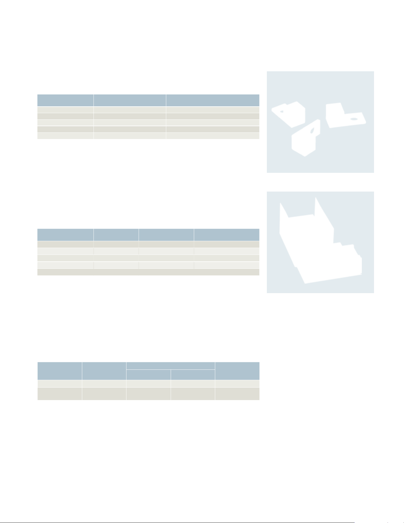
SSH150 ECHV300 ECHS200
Interchangeable hubs
Conduit hubs are available for Type 3R, 12 and 4/4X applications. 30-200A Type 3R
Switches are provided with a conduit hub provision and a removable hub plate on
their top rainsheds.
Field replacement kits and neutral barrier kits
All Heavy Duty Switches are field convertible for crimp type lugs. When
compression lugs are required for 30- 100A switches, a neutral barrier kit is
required for 1-Phase, 3W or 3-Phase, 4W applications. When compression
lugs are required on 400-1200A switches, lug mounting kits are required.
Lugs
30-100A Switches are suitable for use with 60ºC or 75ºC wire. 100-1200A are
suitable for use with 75ºC rated wire.
General and heavy duty
Hub and lug data
SL0420
Note: 30 thru 200A. Type 3R Switches have removable hub
plates on rainshed. 400A and larger Type 3R Switches have
no provisions for mounting hubs. Drill or punch hole in the
field to accommodate hub size desired.
Conduit
size
(inches)
Catalog
number Used on
Type 3R
1)
Cover
ECHA000
30A GD Only
C\v
ECHA075
1
ECHA100
1 Z\v
ECHA125
Cover
ECHS000
60–200A GD
30–200A HD
C\v
ECHS075
1
ECHS100
1 Z\v
ECHS125
1 Z\x
ECHS150
2
ECHS200
2 Z\x
ECHS250
2 Z\x
ECHV250
400–1200A
3
ECHV300
3Z\x
ECHV350
4
ECHV400
Type 4/4X
2)
C\v
SSH075
30–200A
1
SSH100
1Z\v
SSH125
1Z\x
SSH150
2
SSH200
2 Z\x
SSH250
400–600A
3
SSH300
3 Z\x
SSH350
4
SSH400
Field replacement kits and neutral barrier kits
Switch ampere rating Catalog number Kit description
30
HCL612
Neutral Barrier Kit
60 & 100
HCL623
Neutral Barrier Kit
400
HCM65A
240V/600V Fusible Kit
400
HNCM65A
240/600V Non-
Fusible
Kit
600
HCM66A
240V/600V Fusible Kit
600
HNCM66A
240V/600V Non-
Fusible
Kit
800 & 1200
5)
HCL65678 n
1 Pole, Compression Lug Mounting Kit
Multiple padlock accessory
A tamper-proof device to provide for multiple padlocking to meet OSHA or plant
requirements. Accepts up to 6 1/4” padlocks. Catalog number SL0420. Standard
Carton-12.
Wire ranges (Line, load and standard neutral)
Switch
ampere
rating
Wire range with
wire bending space
per NEC requirements Lug wire range
30GD
#14-8 AWG (Cu/AI
)
6)
#14-6 AWG (Cu/Al)
30HD #14-6 AWG (Cu/AI) #14-2 AWG (Cu/Al)
60
8)
10)
#14-3 AWG (Cu/AI) #14-2 AWG (Cu/Al)
100
11)
#14-1/0 AWG (Cu/Al) #14-1/0 AWG (Cu/Al)
200
9)
#6 AWG-250 Kcmil (Cu/Al) #6 AWG-300 Kcmil (Cu/Al)
400
7)
(1) 1/0 AWG-600 Kcmil (Cu/Al)
(2) 1/0 AWG-500 Kcmil (Cu/Al)
(2) 1/0 AWG-600 Kcmil (Cu/Al)
600
7)
(1) 1/0 AWG-600 Kcmil (Cu/Al)
(2) 1/0 AWG-500 Kcmil (Cu/Al)
(2) 1/0 AWG-600 Kcmil (Cu/Al)
800
(3) 1/0 AWG-750 Kcmil (Cu/Al) Line Load
(4) 1/0 AWG-750 Kcmil (Cu/Al) neutral
(3) 1/0 AWG-750 Kcmil (Cu/Al) Line Load
(4) 1/0 AWG-750 Kcmil (Cu/Al) neutral
1200
(4) 3/0 AWG-750 Kcmil (Cu/Al) Line Load
(4) 1/0 AWG-750 Kcmil (Cu/Al) neutral
(4) 1/0 AWG-750 Kcmil (Cu/Al) Line Load
(4) 1/0 AWG-750 Kcmil (Cu/Al) neutral
n Built to order. Allow 3-4 weeks for delivery.
1)
Hubs suitable for 3R Switches.
2)
Also suitable for Type 12 applications.
3)
Neutral Barrier kits are required on 30-100A switches
only and only with 1-Phase / 3W or 3-Phase / 4W
loads. Compression Lugs mounting kits are required
on 400-1200A switches only.
4)
Provides mounting for a single line or load lug.
5)
Provides mounting for (2) compression lugs per
phase on line or load.
6)
Line base lugs (only) are UL approved to accept #14-6
CU/Al cable.
7)
Max. wire size for height reduced switches is 500
kcmil (Cu/Al).
8)
All but 60A GD & Compact HD NF switches are also
UL approved for #2 Cu/Al conductors.
9)
All 200A Heavy Duty Switches have a wire range
& wire bending space for (1) #6-300 Kcmil (Cu/Al).
10)
Also for 30A oversized heavy duty switches.
11)
Also for 60A oversized heavy duty switches.
26 27
Heavy Duty
Crimp lug application data
Heavy Duty Switches are UL approved to accept the following
field installed compression lugs:
Wire
size
Burndy Thomas-Betts Ilsco
CU ONLY CU/AL CU ONLY CU/AL CU ONLY CU/AL
Heavy Duty 30 Amp
1)
#14-10 — — — 60096
60097
— —
#8 YA8C-L Box
YA8C-L1 Box
— 54104
54130
60101
60102
61102
CRA-8 ACL-8
ACN-8
#6 — — — — — —
Heavy Duty 60 Amp
2)
#14-10 — — 256-30695-1352 60097 — —
#8 YA8C-L1 Box
YA8C-TC14
YA8CA3 54130
54930BE
60102
61102
— ACL-8
#6 YA6C-L Box YA6C YA6CA1 54105
54905BE
60107
61107
CRB-6
CRB-6L
ACL-6
#4 — — 54106 61112 CRB-4 —
Heavy Duty 100 Amp
2)
#6 YA6C-L Box YA6C YA6CA1 54105 54905BE 61107 60107 CRB-6 CRB-6L ACL-6
#4 YA4C-L Box YA4C YA4CA1 54106 54906BE 61112 60112 CRB-4 CRB-4L ACL-4
#2 YA2C-L2 Box YA2C YA2CA5 54107 54907BE 61116 CRB-2 CRB-2L ACL-2
#1 YA1C-L2 YA1C — 54108 61122 CRB-1-14 CRA-1L —
1/O — — — 61130 — —
Heavy Duty 200 Amp
#2 YA2C-L Box YA2C YA2CA1 54142-TB 60117 CRB-2 CRB-2L IACL-2 ACN-2
#1 YA1C-L Box YA1C YA1CA1 54147 54947BE 60123 CRA-1-38 CRA-1L ACN-1
1/0 YA25-L Box YA25 YA25A1 54153-TB 54949BE 60129 61130 CRA-0 CRA-1/0L IACL-1/0 ACN-1/0
2/0 YA26-L3 YA26 YA26A6 54158 54910BE
256-30695-1229
60135 61136 CRA-2/ 0 CRA-2/0L ACL-2/0
IACL-2/0
3/0 YA27-L3 YA27 YA27A1 54163-TB 60141 61142 CRC-3/0 CRB-3/0L IACL-3/0 ACL-3/0
4/0 YA28-L3
YA28-TC38
YA28A1 54168
256-30695-1253
61148
61147
CRC-4/0 CRB-4/0L IACL-4/0
ACL-4/0
250 Kcmil YA29-L7 — 54173 54913BE 61156 CRA-250 CRA-250L IACL-250
300 Kcmil — — — 61162 — —
Heavy Duty 400 Amp & 600 Amp
3)
#10 YA25-L4 Box
YA25-TC38
YA25A3 54109 54909BE 60130 — ACL-1/0
#2/0 YA26-L Box YA26 YA26A6 54110 54910BE 60136 CSWS-2/0-38
CLNS-2/0-38
ALNN-2/0-38
ACL-2/0
#3/0 YA27-L4 Box YA27A1 54111
54965BE06
60142 CSWS-3/0-38
CLNS-3/0-38
ALNN-3/0-38
ACL-3/0
#4/0 YA28-L4 Box
YA28-TC38
YA28A1 54112
54970BE06
60148 CSWS-4/0-38
CLNS-4/0-38
ALNN-4/0-38
ACL-4/0
250 Kcmil YA29-L4 — 54174
54913BE06
61156
60154
CSWS-250-38
CLNS-250-38
ALNN-250-38
300 Kcmil YA30-L24 — 54179
54914BE60B
61162 CSWS-300-38
CLNS-300-38
ALNN-300-38
350 Kcmil YA31-L11 — 256-30695-112 61165
60165
CSWS-350-38
CLNS-350-38
—
400 Kcmi — — 54116NT06
54916BENT06
60168NT06 CSWN-500-38 —
500 Kcmil — — 54118NT06 — — —
1)
If compression lugs are used for the neutral, order compression lug neutral barrier kit HCL612.
2)
If compression lugs are used for the neutral, order compression lug neutral barrier kit HCL623.
3)
Use compression lug mounting kit per table on previous page.
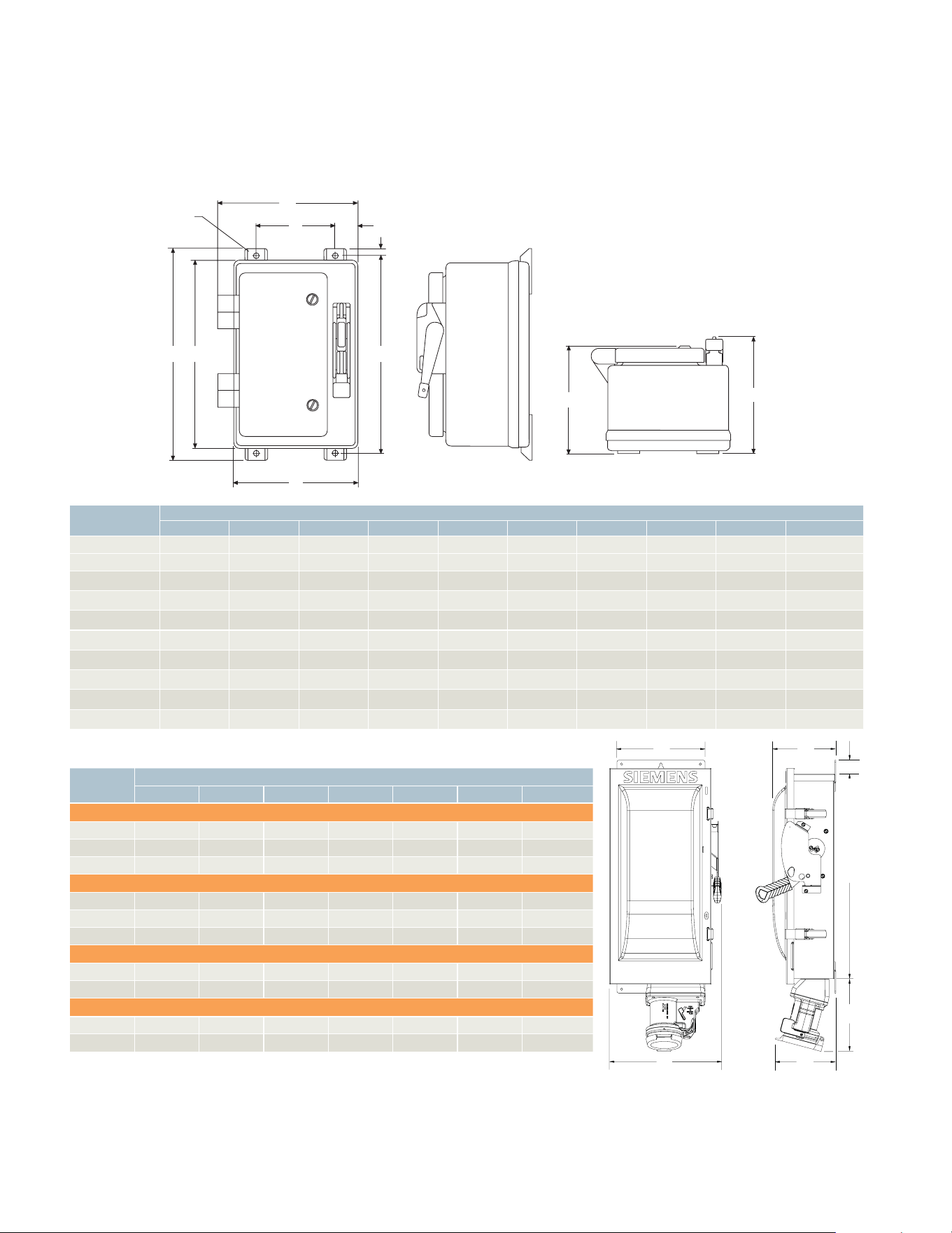
28 29
Special application safety switches
Non-metallic and interlocked receptacle switch
Dimension drawings
G
C
W
F
E
B
A
H
4 X 0.50
(12.70)
J
D
B
C
D
E
A
G
F
Catalog
number
Dimensions (Inches) non-metallic
H W D A B C E F G J
HF321NX 18.75 12.11 10.25 16.59 10.97 7 .00 17.50 1.98 .46 9.20
HF322NX 18.75 12.11 10.25 16.59 10.97 7.00 17.50 1.98 .46 9.20
HF361NX
1
)
18.75 12.11 10.25 16.59 10.97 7.00 17.50 1.98 .46 9.20
HF362NX
1
)
18.75 12.11 10.25 16.59 10.97 7.00 17.50 1.98 .46 9.20
HF363NX
1
)
26.95 14.87 13.25 24.84 13.72 6.25 25.75 3.75 .46 12.15
HF364NX
1
)
33.41 27.47 13.19 31.31 26.31 18.50 32.25 3.91 .47 12.10
HNF361NX
1
)
18.75 12.11 10.25 16.59 10.97 7.00 17.50 1.98 .46 9.20
HNF362NX
1
)
18.75 12.11 10.25 16.59 10.97 7.00 17.50 1.98 .46 9.20
HNF363NX
1
)
26.95 14.87 13.25 24.84 13.72 6.25 25.75 3.75 .46 12.15
HNF364NX
1
)
33.41 27.47 13.19 31.31 26.31 18.50 32.25 3.91 .47 12.10
VBII interlocked receptacle switches
Ampere
rating
Dimensions (Inches)
A B C D E F G
Cr-H Type Fusible (240 & 600V)
30 14.27 7.42 9.02 6.22 1.52 6.1 6.0
60 16.27 9.17 11.47 6.34 1.52 6.4 7.4
100 21.96 9.65 12.02 6.80 1.52 6.5 7.6
Cr-H Type Non-fusible (600V max)
30 11.12 7.42 9.02 6.22 1.52 6.1 6.0
60 16.27 9.17 11.47 6.34 1.52 6.4 7.4
100 21.96 9.65 12.02 6.80 1.52 6.5 7.6
Pyle-National Type Fusible (240 & 600V)
30 14.27 7.42 9.02 6.22 1.52 3.5 3.0
60 16.27 9.17 11.47 6.34 1.52 5.0 4.5
Pyle-National Type Non-fusible (600V max)
30 11.12 7.42 9.02
a
6.22 1.52 3.5 3.0
60 16.27 9.17 11.47
a
6.34 1.52 5.0 4.5
1)
Dimensions also apply to “L” suffix switches (less lugs).
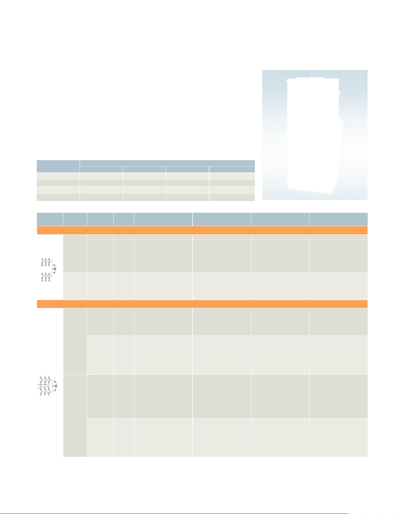
28 29
Description and application
Double throw safety switches are intended to transfer loads from one power
source to another. All two- and three pole double throw switches are suitable
for use as service equipment. All are UL listed. Switches are rated for use on
systems up to 10,000A when protected with Class H fuses or 100,000A when
protected with Class R or Class T fuses. They can also be used to connect a
single source of power to either of two loads. In this application it is necessary
to field modify fusible switches so that the fuses are on the load side of the
switching mechanism. A cover interlock is provided on all ampere ratings. The
operating handle may be padlocked in the OFF position.
Double throw switches
Fuse capabilities of fusible switches
Amp
rating
Fuse type
H R T J
30 & 60A, 240V Std Yes (kit) No No
30 & 60A, 600V Std Yes (kit) No
Yes
3)
100 & 200A Std Yes (kit) Yes (kit)
Yes
3)
400 & 600A DTF No No
Yes
3)
Std
4)
Double throw switches
System Voltage
Number
of poles Amps
Type 1 – Indoor
Catalog number
Type 3R – Outdoor
1)
Catalog number
Type 12/3R Industrial
Catalog number
Type 4X – Stainless Steel
Catalog number
Heavy Duty Fusible (30-200A with Class H fuse provisions)
2)
240
Volt AC
or
250
Volt DC
2 200
DTF224 DTF224R — —
3
30
60
100
200
400
600
DTF321
DTF322
DTF323
DTF324
DTF325
DTF326
DTF321R
DTF322R
DTF323R
DTF324R
—
—
—
—
—
—
—
—
—
—
—
—
—
—
600
Volt AC,
250
Volt DC
3
30
60
100
200
400
DTF361
DTF362
DTF363
DTF364
DTF365
—
—
DTF363R
DTF364R
—
—
—
—
—
—
—
—
F353SSDTK
F354SSDTK
F355SSDTK
4)
Heavy Duty Non-Fusible
2)
240
Volt AC
or
250
Volt DC
2
30
60
100
200
400
DTNF221
DTNF222
DTNF223
DTNF224
DTNF225
—
—
—
DTNF224R
DTNF225R
—
—
—
—
—
—
—
—
—
—
3
30
60
100
200
400
600
800
DTNF321
DTNF322
DTNF323
DTNF324
DTNF325
DTNF326
DTNF327
—
—
DTNF323R
DTNF324R
—
—
—
—
—
—
—
—
—
—
—
—
—
—
—
—
—
600
Volt AC
or
250
Volt DC
3
30
60
100
200
400
600
800
1200
DTNF361
DTNF362
DTNF363
DTNF364
DTNF365
DTNF366
DTNF367
DTNF368
DTNF361R
DTNF362R
DTNF363R
DTNF364R
DTNF365R
DTNF366R
DTNF367R
DTNF368R
DTNF361J
DTNF362J
DTNF363J
DTNF364J
NF355HDTK
—
—
—
DTNF361S
DTNF362S
DTNF363S
DTNF364S
NF355SSDTK
—
—
—
4
5)
30
60
100
200
400
600
800
—
—
—
NF454DTK
NF455DTK
NF456DTK
NF457DTK
NFR451DTK
NFR452DTK
NFR453DTK
NFR454DTK
NFR455DTK
NFR456DTK
NFR457DTK
—
—
—
—
—
—
—
—
—
—
NF454SSDTK
—
—
—
1)
Use HS Type hubs for 30–200A switches; 400A
and larger switches do not have hub provisions.
ON
OFF
ON
ON
OFF
ON
ON
OFF
ON
ON
OFF
ON
2)
All Heavy Duty double throw switches with catalog
numbers starting with “DT” are rated 200,000 AIC
max. when protected by Class R, J or T fuses. Fuse
ampere rating must not exceed switch ampere rating.
3)
Move load base.
4)
Catalog No. F355SSDTK will accept Class T Fuse only.
5)
Four pole switches are not approved for service
entrance.
30 31
30 31
1)
Use HS Type hubs for 30-200A switches.
2)
Not for fusible stainless or 400A Type 12 & 4X switches.
3)
Also for fusible stainless and 400A Type 12 & 4X switches.
4)
The following ground lugs are provided as standard in 200A and larger switches
200-(1) #14-4 Cu/Al 400-800A-(3) #6-250MCM Cu/Al.
5)
One aux. required for normal and one required for emergency switch line base.
Double throw switches
System Voltage
Number
of poles Amps Type 3R
– Outdoor
1)
less neutral Type 3R – Outdoor
1)
with neutral
General Duty Non-Fusible
240
Volt AC
2 100
200
DTGNF223R
DTGNF224R
DTGNF223NR
DTGNF224NR
3 100
200
DTGNF323R
DTGNF324R
DTGNF323NR
DTGNF324NR
Accessories – 2 and 3 pole type "DT" switches only
2)
Description
Catalog
number
Neutral
Kits
30A
60 & 100A
200A
400 & 600A
800 & 1200A
HNC612
HN263
HNC264
HN678
HND678
Equipment
Ground Kit
30-200A (2) #14-4 AWG
400& 600A (1) #14-2/0
400& 600A (8) #6-350 Kcmil
HG61234
HG656
HG678
Auxiliary
Contacts
(HD only)
(two required
per switch)
5)
30-200A with (1) NO & (1) NC Contacts
30-200A with (2) NO & (2) NC Contacts
400-1200A with (1) NO & (1) NC Contacts
400-1200A with (2) NO & (2) NC Contacts
HA161234
HA261234
HA165678
HA265678
Class R Fuse
Clip Kits
(two required
per switch)
30A, 240V Kit
30A, 600V Kit / 60A, 240V Kit
60A, 600V Kit
100A Kit
200A Kit
HR21
HR612
HR62
HR63
HR64
Class T Fuse
Adapter Kits
(two required
per pole)
100A, 240V Kit
100A, 600V Kit
200A, 240V Kit
200A, 600V Kit
HT23
HT63
HT24
HT64
Type 3R Hubs
(30-200A)
For C\v ” Conduit
For 1” Conduit
For 1Z\v ” Conduit
For 1Z\x” Conduit
For 2” Conduit
For 2Z\x” Conduit
HS075
HS100
HS125
HS150
HS200
HS250
Wire ranges (Line, load and neutral) per NEC requirements
30-200A – 2, 3 & 4 pole switches
Switch
ampere
rating
Wire range (Cu/Al)
New VBII design
Line, load and neutral
30
(1) #14-6
60
(1) #14-2
100 (1) #14-1/0 AWG
200 (1) #6-250 Kcmil
400-1200A – 2, 3 pole switches
Switch
ampere
rating
Wire range (Cu/Al)
New VBII design
Line, load and neutral
400
(1) 1/0 AWG - 750 Kcmil or
(2) 1/0 AWG - 250 Kcmil
600
(2) 1/0 AWG–500 Kcmil
800
(2) 1/0 AWG - 750 Kcmil or
(3) 1/0 AWG - 500 Kcmil
1200
(3) 1/0 AWG - 600 Kcmil or
(4) 1/0 AWG - 500 Kcmil
400-800A – 4 pole switches
Switch
ampere
rating
Wire range (Cu/Al)
New VBII design
Range line, load and neutral
400
(2) 1/0 AWG–300 kcmil or
(1) 1/0 AWG–750 kcmil
600
(2) 250-500 Kcmil
800
(3) 250-500 Kcmil
Accessories – 4 pole and type "F" and "NF" switches only
3)
Description
Catalog
number
Auxiliary switch (two
required per switch)
30-800A (1) NO, (1) NC
5)
(2) NO, (2) NC
5)
DS200EK1
DS200EK2
Ground lug kit
4)
30-60-100A
200A
400-600-800A
DSG100GK
DSG200GK
DSG468GK
Hubs 30-60-100A Use Type HR hubs
200-400A Use Type SSH 4, 4X hubs
600-800A Use Type SSH 4, 4X hubs
—
—
—
Neutrals (for fusible
stainless steel and 400A
Type 12 & 4X only)
30-60-100A
200A
400A Fusible
DT100NK
DT200NK
DS800NK
Replacement parts – 2 and 3 pole type “DT” switches only
2)
Description
Catalog
number
Type 1, 3R & 12 replacement handle
Type 4X Replacement handle
30-200A
30-200A
HHD61234
HHD61234S
Type 4X replacement handle 400-1200A
HHD65678
Maximum horsepower ratings fused
Ampere
rating
1-Phase AC 3-Phase AC
250V DC240V 240V 480V 600V
30 3
7 Z\x
15 20 5
60 10 15 30 50 10
100 15 30 60 75 20
200 15 60 125 150 40
400 — 125 125 125 50
600 — 125 — — 50
Maximum horsepower ratings non-fused
Ampere
rating
1-Phase AC 3-Phase AC
250V
DC240V 240V 480V 600V
30 5 10 20 30 5
60 10 20 50 60 10
100 15 40 75 100 20
200 15 60 125 150 40
400-800 — 125 250 350 50
Double throw switches
General duty, accessories, lug data and horsepower ratings
ON
OFF
ON
ON
OFF
ON
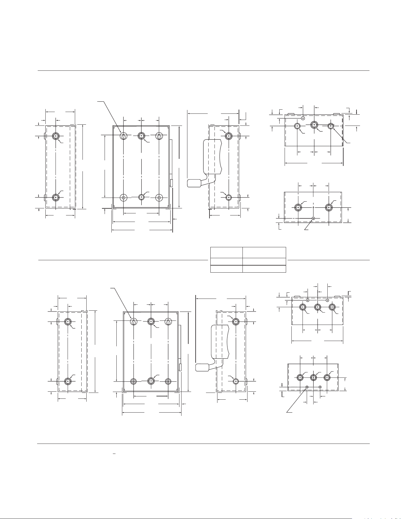
30 31
30 31
1)
Use HS Type hubs for 30-200A switches.
2)
Not for fusible stainless or 400A Type 12 & 4X switches.
3)
Also for fusible stainless and 400A Type 12 & 4X switches.
4)
The following ground lugs are provided as standard in 200A and larger switches
200-(1) #14-4 Cu/Al 400-800A-(3) #6-250MCM Cu/Al.
5)
One aux. required for normal and one required for emergency switch line base.
Detailed dimension drawings
C
L
1.13
[28.70]
1.94
[49.28]
1.94
[49.28]
.38
[9.65]
.28 [7.11] Dia. Grounding K.O. [4 Places]
B B
B
.97
[24.64]
.97
[24.64]
1.13
[28.7]
C
L
.38
[9.65]
.10
[2.54]
B
B
B
.97
[24.64]
.97
[24.64]
1.94
[49.28]
1.94
[49.28]
7.19
[30.23]
[Door]
1.00
[25.4]
1.00
[25.4]
1.13
[28.7]
3.00
[76.2]
Door
2.81
[71.37]
8.19
[208.02]
[Door]
6.13
[155.70]
7.97
[202.44]
.85
[21.59]
2.50
[63.50]
2.50
[63.50]
5.38
[136.65]
5.00
[127.00]
5.97
[151.64]
7.69
[195.33]
C
L
.50
[12.70]
[4] .25 [6.35] Dia.
Mounting Holes
B
B
A
B
B
B
1.00
[25.4]
1.13
[28.7]
2.94
[49.28]
.85
[21.59]
1.00
[25.4]
1.00
[25.4]
1.13
[28.7]
3.00
[76.2]
Door
2.81
[71.37]
8.13
[206.5]
[Door]
1.00
[25.4]
.85
[21.59]
2.94
[74.68]
6.13
[155.70]
7.97
[202.44]
.72
[18.29]
1.75
[44.45]
5.38
[136.35]
1.75
[44.45]
3.50
[88.9]
5.22
[132.59]
5.94
[150.88]
C
L
.50
[12.7]
.94
[23.88]
[4] .25 [6.35] Dia.
Mounting Holes
B
B
A
A
B
B
C
L
1.13
[28.7]
1.00
[25.4]
1.00
[25.4]
.25 [6.35] Dia.
Grounding K.O.
B
B
.38
[9.65]
1.38
[35.5]
1.13
[28.7]
C
L
.38
[9.65]
.10
[2.54]
.91
[23.1]
1.63
[41.40]
1.63
[41.40]
5.44
[36.58]
[Door]
A
A
B
Figure 1
Figure 2
Type 1 (Indoor)
30 Amp General Duty (2-Pole)
30 Amp General Duty (3-Pole)
Dimensions shown in inches and millimeters [ ].
Dimensions shown accurate to
+
1/8 inch.
( (
KNOCKOUT CONDUIT
CODE SIZE
A (Concentric)
.50 .75
B (Concentric) .50 .75 1.00
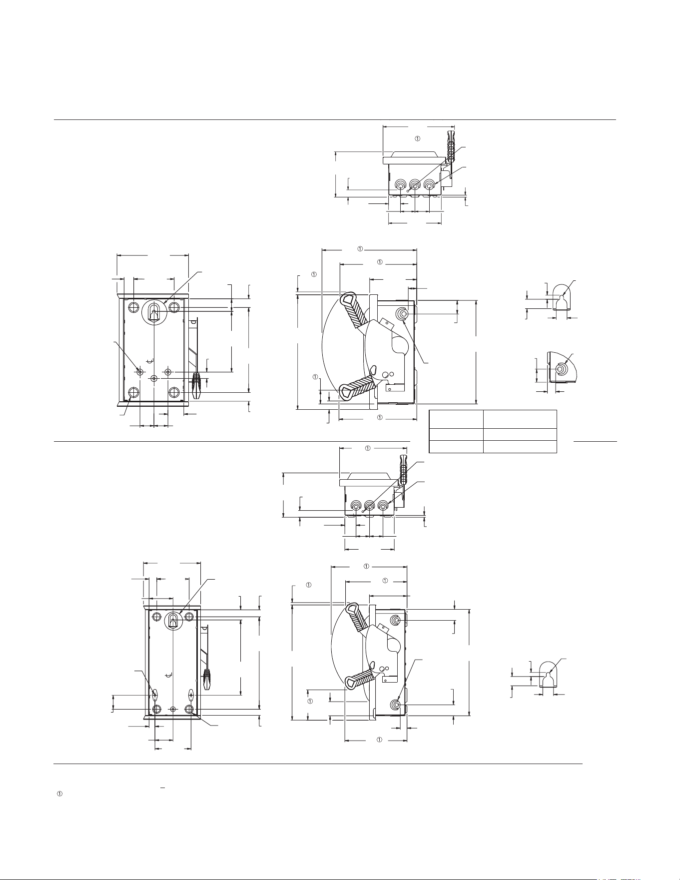
32 33
Type 1 (Indoor)
30 Amp Heavy Duty Non-Fusible
60 Amp Compact Heavy Duty Non-Fusible
60 Amp General Duty Non-Fusible
30 Amp Heavy Duty Fusible
60 Amp General Duty Fusible
1.71
43[ ]
6.52
166[ ]
1.35
34[ ]
72. AID
7[ ]
9 01
7.67
195[ ]
4.34
110[ ]
1.04
26[ ]
.94
24[ ]
9.12
232[ ]
.95
24[ ]
1.50
38[ ]
1.50
38[ ]
.68
17[ ]
SEE DETAIL
C
A
(4)
OF BOX
B
9.01
229[ ]
5.71
145[ ]
.91
23[ ]
6.64
169[ ]
1.51
38[ ]
1.80
46[ ]
1.80
46[ ]
.25
6[ ]
[ ] [ ]
.25 DIA GROUND KNOCKOUT
TOP & BOTTOM
B
(3)
TOP & BOTTOM
72. AID
7[ ]
.75
19[ ]
.65
16[ ]
.28
7[ ]
DETAIL
C
.91
23[ ]
1.46
37[ ]
B
LEFT SIDE
1.47
37[ ]
.32
8[ ]
10.17
258[ ]
.92
23[ ]
.91
23[ ]
5.05
128[ ]
8.25
210[ ]
8.35
212[ ]
1
2.31
313
[
]
11.11
282[ ]
1.45
37[ ]
B
LEFT &
RIGHT SIDE
1.35
34[ ]
1.04
26[ ]
4.34
110[ ]
4.84
123[ ]
8.25
209[ ]
10.17
258[ ]
3.21
82[ ]
2.42
62[ ]
4.07
103[ ]
.82
21[ ]
.79
20[ ]
5.05
128[ ]
1.46
37[ ]
1.46
37[ ]
14.26
362[ ]
.91
23[ ]
7.67
195[ ]
15.45
393[ ]
1.90
48[ ]
12.40
315[ ]
.94
24[ ]
8.35
212[ ]
.32
8[ ]
1.88
48[ ]
10.11
257[ ]
SEE DETAIL
C
OF BOX
A
(4)
.27 DIA (3)
[7]
B
(2)
LEFT &
RIGHT SIDE
.91
23[ ]
1.51
38[ ]
1.80
46[ ]
1.80
46[ ]
9.01
229[ ]
6.64
169[ ]
.25
6[ ]
5.95
151[ ]
B
(3)
TOP & BOTTOM
.25 DIA GROUND KNOCKOUT
TOP & BOTTOM
72. AID
7[ ]
.75
19[ ]
.65
16[ ]
.28
7[ ]
DETAIL
C
Figure 3
Figure 4
KNOCKOUT CONDUIT
CODE SIZE
A (Concentric)
.50 .75
B (Tangential) .50 .75 1.00
Dimensions shown in inches and millimeters [ ].
Dimensions shown accurate to
+
1/8 inch.
Dimensions shown apply to heavy duty switches only.
Detailed dimension drawings
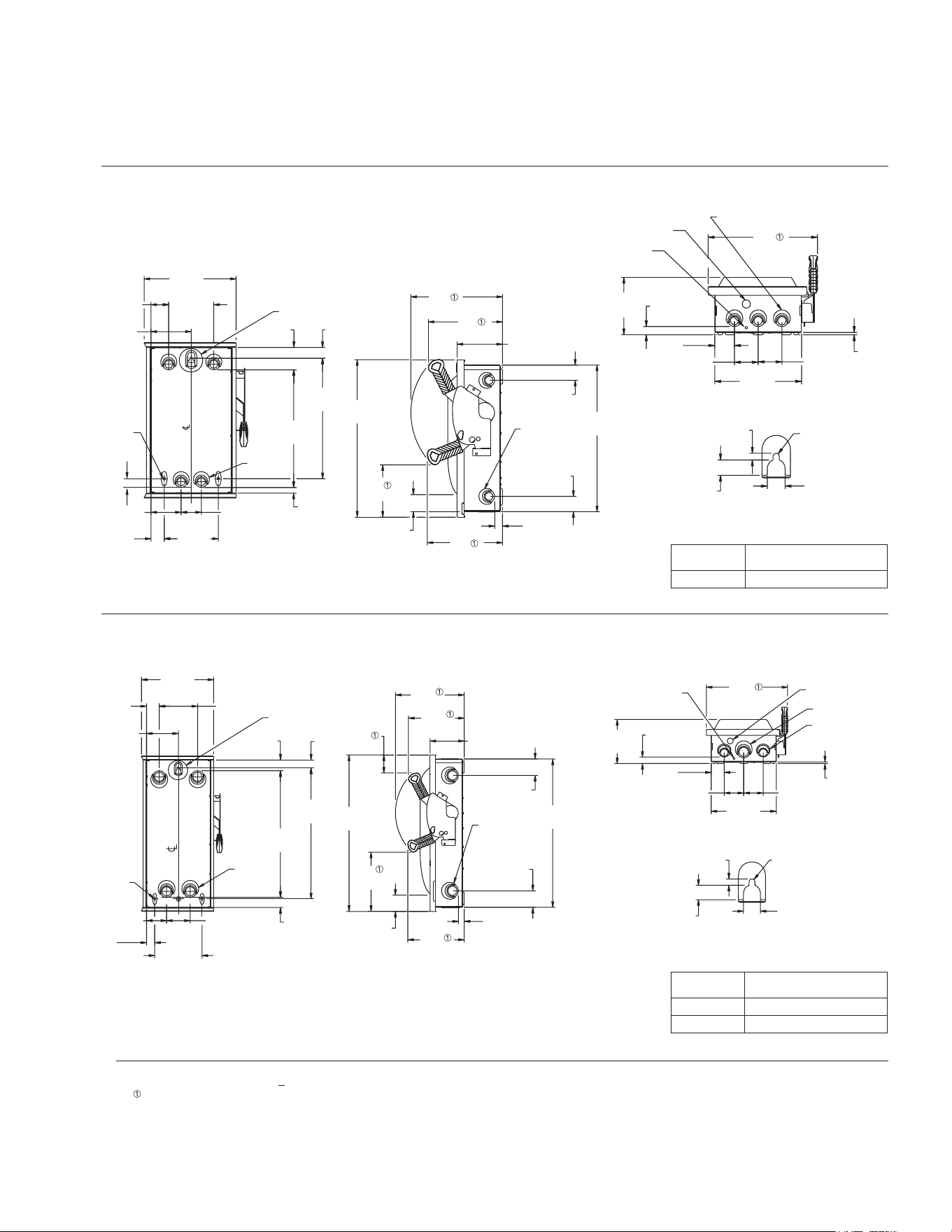
32 33
Type 1 (Indoor)
60 Amp Heavy Duty
(Also 30 Amp Oversized Heavy Duty)
100 Amp General and Heavy Duty
6.00
152[ ]
3.35
85[ ]
2.25
57[ ]
4.47
114[ ]
1.19
30[ ]
.63
16[ ]
10.19
259[ ]
1.47
37[ ]
1.97
50[ ]
5.00
127[ ]
13.04
331[ ]
13.36
339[ ]
2.48
63[ ]
SEE DETAIL
B
A
(4)
OF BOX
.27 DIA (3)
[7]
.76
19[ ]
10.17
258[ ]
8.25
209[ ]
5.79
147[ ]
16.26
413[ ]
1.69
43[ ]
1.69
43[ ]
.87
22[ ]
5.05
128[ ]
8.35
212[ ]
17.46
443[ ]
1.89
48[ ]
A
(2)
LEFT &
RIGHT SIDE
9.15
232[ ]
11.53
293[ ]
2.07
53[ ]
2.50
64[ ]
2.50
64[ ]
.25
6[ ]
6.08
155[ ]
.87
22[ ]
.88 DIA
KNOCKOUT
.25 DIA GROUND KNOCKOUT
TOP & BOTTOM
A
(3)
TOP & BOTTOM
72. AID
7[ ]
.65
16[ ]
.75
19[ ]
.28
7[ ]
DETAIL
B
KNOCKOUT CONDUIT
CODE SIZE
A (Tangential) .50 .75 1.00 1.25
5.68
144[ ]
DIA (3).27
7[ ]
1.19
30[ ]
1.88
48[ ]
4.71
120[ ]
1.51
38[ ]
10.68
271[ ]
1.21
31[ ]
3.50
89[ ]
2.96
75[ ]
7.00
178[ ]
18.72
475[ ]
19.38
492[ ]
1.61
41[ ]
SEE DETAIL
C
B (4)
OF BOX
2.42
62[ ]
10.17
258[ ]
2.68
68[ ]
8.76
223[ ]
21.95
557[ ]
2.45
62[ ]
2.43
62[ ]
.85
22[ ]
8.35
212[ ]
5.05
128[ ]
8.25
210[ ]
23.15
588[ ]
B
(2)
LEFT &
RIGHT SIDE
72. AID
7[ ]
.65
16[ ]
.28
7[ ]
.75
19[ ]
DETAIL
C
9.64
245[ ]
1.94
49[ ]
2.88
73[ ]
2.88
73[ ]
.98
25[ ]
6.52
166[ ]
12.01
305[ ]
.25
6[ ]
178[ ]
.25 DIA GROUND KNOCKOUT
TOP & BOTTOM
B
TOP & BOTTOM
A
(2)
TOP & BOTTOM
.88 DIA KNOCKOUT
KNOCKOUT CONDUIT
CODE SIZE
A (Tangential) .75 1.00 1.25 1.50
B (Tangential) 1.00 1.25 1.50 2.00
Figure 5
Figure 6
Dimensions shown in inches and millimeters [ ].
Dimensions shown accurate to
+
1/8 inch.
Dimensions shown apply to heavy duty switches only.
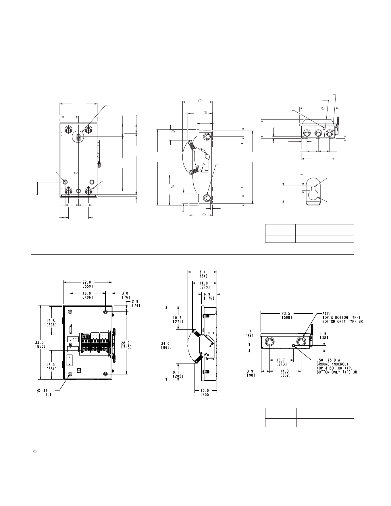
34 35
Detailed dimension drawings
Dimensions shown in inches and millimeters [ ].
Dimensions shown accurate to
+
1/8 inch.
Dimensions shown apply to heavy duty switches only.
Type 1 (Indoor)
200 Amp General and Heavy Duty
400 / 600 Amp General and Heavy Duty Non-Fusible
DIA (4)
.33
8[ ]
8.20
7.19
183[ ]
.81
21[ ]
15.39
391[ ]
3.10
3.68
93[ ]
5.10
130[ ]
3.81
97[ ]
25.22
640[ ]
22.43
570[ ]
5.50
140[ ]
5.50
140[ ]
SEE DETAIL
C
A
(4)
OF BOX
208[ ]79[ ]
9.74
247[ ]
4.39
112[ ]
10.17
258[ ]
12.33
313[ ]
12.42
315[ ]
29.90
759[
]
2.37
60[ ]
2.31
59[ ]
31.07
789[ ]
.81
21[ ]
6.36
162[ ]
4.37
111[ ]
A
(2)
LEFT &
RIGHT SIDE}
16.98
431[ ]
8.19
208[ ]
.87
22[ ]
2.45
62[ ]
4.88
124[ ]
4.88
124[ ]
14.62
371[ ]
.20
5[ ]
.88 DIA KNOCKOUT
TOP & BOTTOM
.25 DIA GROUND KNOCKOUT TOP & BOTTOM
A
(3)
TOP & BOTTOM
KNOCKOUT CONDUIT
CODE SIZE
A (Tangential) 1.25 1.50 2.00 2.50
Figure 7
Figure 8
KNOCKOUT CONDUIT
CODE SIZE
A (Tangential) 2.00 2.50 3.00 3.50
.47
12[ ]
83. AID
10[ ]
00.1 AID
25[ ]
1.44
37[ ]
DETAIL
C
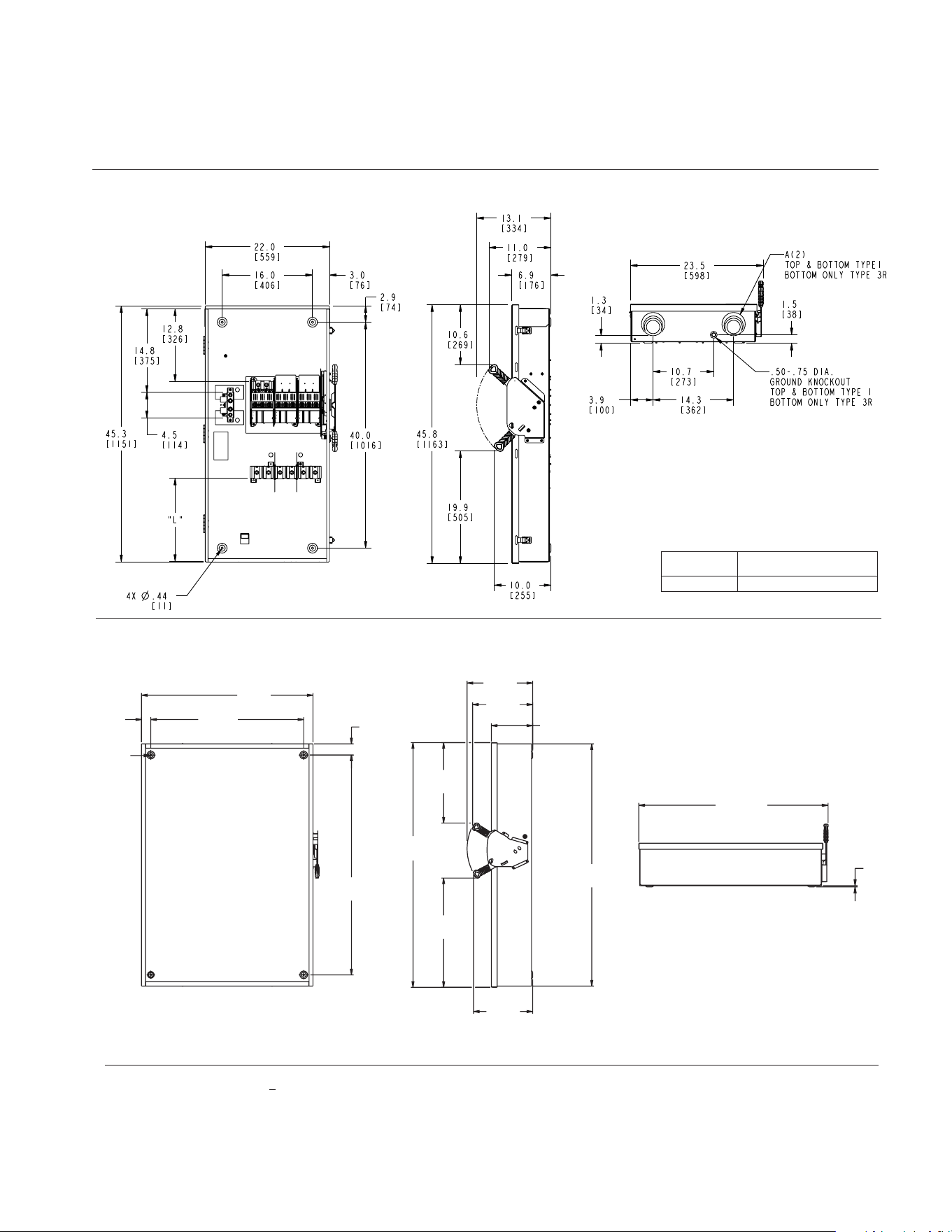
34 35
14.68
373[ ]
38.40
975[ ]
9.24
235[ ]
13.42
341[ ]
54.25
1378[ ]
18.46
469[ ]
54.82
1392[ ]
24.02
610[ ]
34.25
870[ ]
2.50
64
49.25
1251[ ]
13.25
337[ ]
39.96
1015[ ]
.25
6[ ]
2.07
53[ ]
.56 Dia (4)
14[ ]
Type 1 (Indoor)
400 / 600 General and Heavy Duty Fusible
800 / 1200 Amp Heavy Duty Non-Fusible
Figure 9
Figure 10
No knockouts in the enclosures.
KNOCKOUT CONDUIT
CODE SIZE
A 2.00 2.50 3.00 3.50
Dimensions shown in inches and millimeters [ ].
Dimensions shown accurate to
+
1/8 inch.
3.20
[ 81 ]
32
[ 813 ]
2.79
[ 71 ]
55.16
[ 1401 ]
54.67
[ 1389 ]
40.00
[ 1016 ]
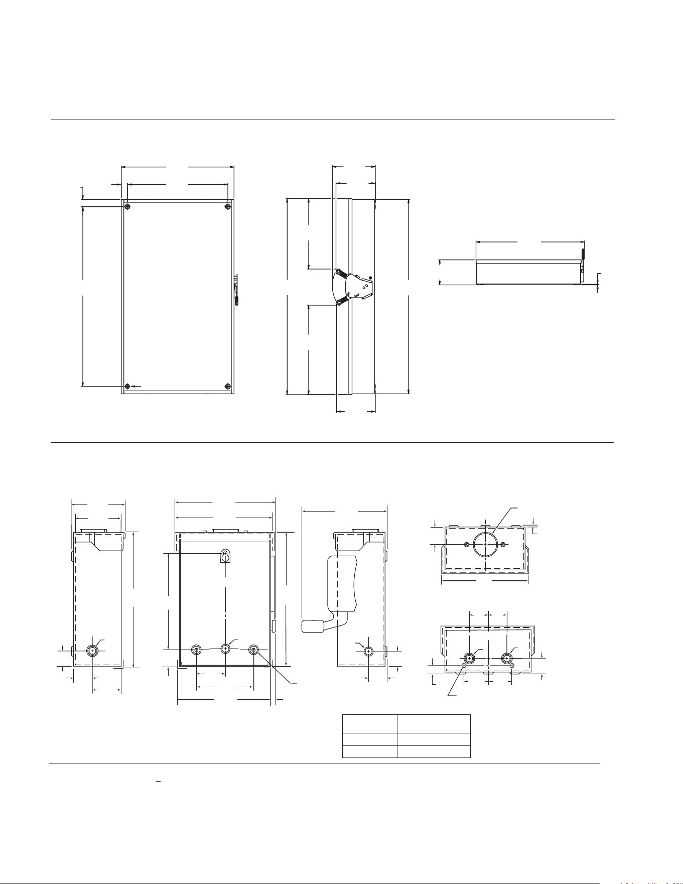
36 37
Detailed dimension drawings
Dimensions shown in inches and millimeters [ ].
Dimensions shown accurate to
+
1/8 inch.
C
L
1.00
[ 25.4 ]
1.00
[ 25.4 ]
.31
(7.87)
.28 (7.11)
DIA GROUNDING KNOCKOUT (2) PLACES
B
B
1.69
[ 42.93 ]
1.69
[ 42.93 ]
1.13
[ 28.7 ]
1.31
[ 33.27 ]
C
L
.10
[ 2.54 ]
Type HA Outdoor
Hub Provision
5.63
[ 143.0 ]
1.00
[ 25.4 ]
3.13
[ 79.50 ]
2.94
[ 74.68 ]
8.16
[ 207.26 ]
(Door)
1.13
[ 28.7 ]
6.13
[ 155.7 ]
8.07
[ 204.98 ]
.85
[ 21.59 ]
5.38
[ 136.65 ]
1.75
[ 44.5 ]
3.50
[ 88.9 ]
5.22
[ 132.59 ]
C
L
5.44
[ 138.18 ]
(Door)
.
50
[ 12.7 ]
A
A
B
.85
[ 21.59 ]
5.94
[ 150.88 ]
1.13
[ 28.7 ]
2.81
[ 71.37 ]
(3) .25 (6.35) DIA
MOUNTING HOLES
14.68
373[ ]
32
813[ ]
3.20
81[ ]
38.40
975[ ]
61.25
1556[ ]
67.16
1706[ ]
24.02
610[ ]
30.46
774[ ]
13.24
336[ ]
13.44
341[ ]
66.67
1693[ ]
9.24
236[ ]
.25
6[ ]
40.00
1016[ ]
2.79
71[ ]
.56 Dia (4)
14[ ]
Type 3R (Outdoor)
30 Amp General Duty (2-Pole)
Type 1 (Indoor)
800 / 1200 Amp Heavy Duty Fusible
Figure 11
Figure 12
No knockouts in the enclosures.
KNOCKOUT CONDUIT
CODE SIZE
A (Concentric)
.50 .75
B (Concentric) .50 .75 1.00
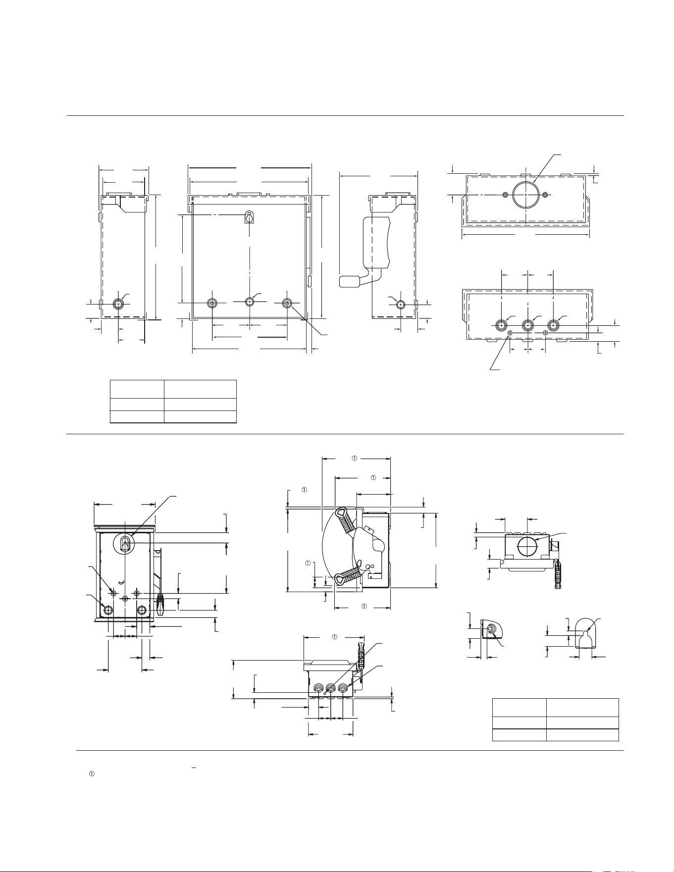
36 37
1.00
[ 25.4 ]
3.13
[ 79.50 ]
2.94
[ 74.68 ]
8.16
[ 207.26 ]
(Door)
1.13
[ 28.7 ]
6.13
[ 155.7 ]
8.07
[ 204.98 ]
.85
[ 21.59 ]
5.38
[ 136.65 ]
2.50
[ 63.50 ]
2.50
[ 63.50 ]
5.00
[ 127 ]
6.97
[ 177.04 ]
C
L
7.19
[ 182.63 ]
(Door)
.50
[ 12.7 ]
A
A
B
.85
[ 21.59 ]
7.69
[ 195.33 ]
1.13
[ 28.7 ]
2.81
[ 71.37 ]
(3) .25 (6.35) DIA
MOUNTING HOLES
C
L
1.94
[ 49.28 ]
1.94
[ 49.28 ]
.28 (7.11) DIA GROUNDING KNOCKOUT (2) PLACES
B B B
1.13
[ 28.7 ]
.97
[24.64]
.97
[24.64]
.38
[ 9.65 ]
1.31
[ 33.27 ]
C
L
.10
[ 2.54 ]
TYPE HA OUTDOOR
HUB PROVISION
7.38
[ 187.45 ]
C
L
1.94
[ 49.28 ]
1.94
[ 49.28 ]
.28 (7.11) DIA GROUNDING KNOCKOUT (2) PLACES
B B B
1.13
[ 28.7 ]
.97
[24.64]
.97
[24.64]
.38
[ 9.65 ]
Type 3R (Outdoor)
30 Amp General Duty (3-Pole)
Figure 13
Figure 14
Dimensions shown in inches and millimeters [ ].
Dimensions shown accurate to
+
1/8 inch.
Dimensions shown apply to heavy duty switches only.
1.60
41[ ]
.32
8[ ]
12.31
313[ ]
10.17
258[ ]
.92
23[ ]
11.11
282[ ]
5.05
128[ ]
8.25
210[ ]
8.35
212[ ]
.90
23[ ]
1.32
34[ ]
3.32
84[ ]
.64
16[ ]
7 91
SEE DETAIL
C
PROVISION FOR TYPE "HS" HUB
72. AID
7[ ]
.65
16[ ]
.28
7[ ]
.75
19[ ]
DETAIL
C
9.01
229[ ]
5.71
145[ ]
.91
23[ ]
1.51
38[ ]
1.80
46[ ]
1.80
46[ ]
6.64
169[ ]
.25
6[ ]
.25 DIA
GROUND KNOCKOUT
B
(3)
.91
23[ ]
1.46
37[ ]
B
LEFT SIDE
DIA (3).27
7[ ]
1.71
43[ ]
6.52
166[ ]
1.32
34[ ]
1.35
34[ ]
1.50
38[ ]
1.50
38[ ]
.95
24[ ]
.68
17[ ]
7.91
201[ ]
4.34
110[ ]
1.04
26[ ]
A
(2)
SEE DETAIL
C
OF BOX
B
DE
KNOCKOUT CONDUIT
CODE SIZE
A (Concentric)
.50 .75
B (Concentric) .50 .75 1.00
KNOCKOUT CONDUIT
CODE SIZE
A (Concentric)
.50 .75
B (Tangential) .50 .75 1.00
30 Amp Heavy Duty Non-Fusible
60 Amp Compact Heavy Duty Non-Fusible
60 Amp General Duty Non-Fusible
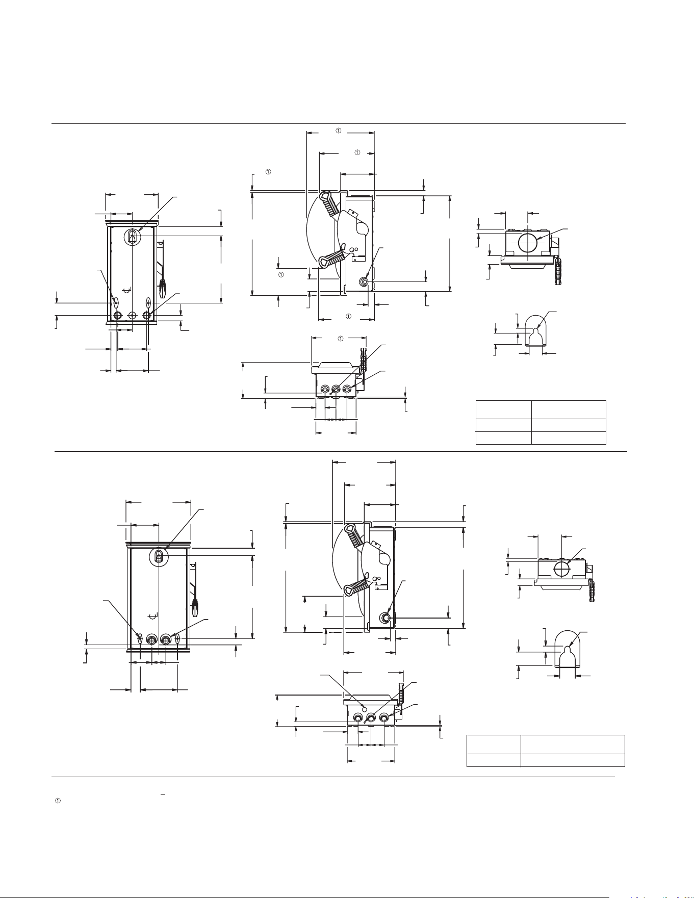
38 39
Detailed dimension drawings
Dimensions shown in inches and millimeters [ ].
Dimensions shown accurate to
+
1/8 inch.
Dimensions shown apply to heavy duty switches only.
4.47
114[ ]
1.19
30[ ]
3.35
85[ ]
2.25
57[ ]
33[ ]
10.43
265[ ]
1.47
37[ ]
6.00
152[ ]
.65
17[ ]
13.36
339[ ]
SEE DETAIL
B
OF BOX
.27 DIA (2)
[ 7 ]
A
(2)
.76
19[ ]
5.05
128[ ]
10.17
258[ ]
8.35
212[ ]
.87
22[ ]
8.25
210[ ]
5.79
147[ ]
16.26
413[ ]
.91
23[ ]
1.69
43[ ]
1.89
48[ ]
.31
8[ ]
17.46
443[ ]
A
LEFT &
RIGHT SIDE
Type 3R (Outdoor)
30 Amp Heavy Duty Fusible
60 Amp General Duty Fusible
KNOCKOUT CONDUIT
CODE SIZE
A (Tangential) .50 .75 1.00 1.25
1.32
33[ ]
.65
17[ ]
4.58
116[ ]
10.43
PROVISION FOR
TYPE "HS" HUB
6.08
155[ ]
.87
22[ ]
11.53
293[ ]
2.08
53[ ]
2.50
64[ ]
9.16
233[ ]
2.50
64[ ]
.25
6[ ]
.25 DIA
GROUND KNOCKOUT
A
(3)
.88 DIA
KNOCKOUT
72. AID
7[ ]
.65
16[ ]
.28
7[ ]
.75
19[ ]
DETAIL
B
Figure 15
Figure 16
7 91
.64
16[ ]
3.32
84[ ]
1.32
34[ ]
PROVISION FOR
TYPE "HS" HUB
1.35
34[ ]
4.84
123[ ]
.82
21[ ]
2.42
62[ ]
7.91
201[ ]
1.04
26[ ]
3.21
82[ ]
.79
20[ ]
4.34
110[ ]
34[ ]
10.11
257[ ]
1.88
48[ ]
A
(2)
OF BOX
SEE DETAIL
C
(3).27 DIA
[ 7 ]
15.45
393[ ]
.32
8[ ]
8.25
209[ ]
5.05
128[ ]
10.17
258[ ]
4.07
103[ ]
8.35
212[ ]
.91
23[ ]
1.46
37[ ]
1.90
48[ ]
14.39
365[ ]
.78
20[ ]
B
LEFT &
RIGHT SIDE
5.95
151[ ]
9.01
229[ ]
.91
23[ ]
1.51
38[ ]
1.80
46[ ]
1.80
46[ ]
6.64
169[ ]
.25
6[ ]
B
(3)
.25 DIA
GROUND KNOCKOUT
72. AID
7[ ]
[ ]
.65
16[ ]
.28
7[ ]
.75
19[ ]
DETAIL
C
KNOCKOUT CONDUIT
CODE SIZE
A (Concentric)
.50 .75
B (Tangential) .50 .75 1.00
60 Amp Heavy Duty
(also 30A Oversized Heavy Duty)
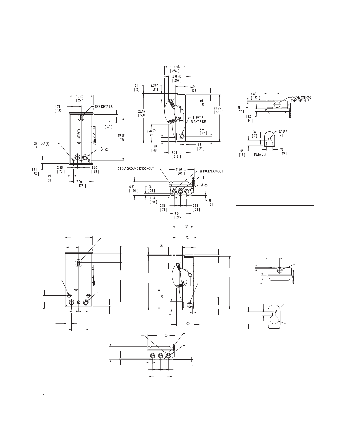
38 39
Type 3R (Outdoor)
100 Amp General and Heavy Duty
(also 60A Oversized Heavy Duty)
200 Amp General and Heavy Duty
KNOCKOUT CONDUIT
CODE SIZE
A (Tangential) .75 1.00 1.25 1.50
B (Tangential) 1.00 1.25 1.50 2.00
29.90
759[ ]
2.31
59[ ]
.81
21[ ]
.91
23[ ]
4.37
111[ ]
9.74
247[ ]
4.39
112[ ]
10.17
258[ ]
12.33
313[ ]
12.42
315[ ]
6.36
162[ ]
.35
9[ ]
31.07
789[ ]
A
LEFT &
RIGHT SIDE
15.94
405[ ]
3.10
79[ ]
8.20
208[ ]
5.10
130[ ]
DIA (4)
.33
8[ ]
7.19
183[ ]
.81
21[ ]
3.68
93[ ]
5.50
140[ ]
5.50
140[ ]
22.43
570[ ]
A
(2)
OF BOX
SEE DETAIL
C
7.30
185[ ]
.65
17[ ]
1.32
34[ ]
PROVISION FOR
TYPE "HS" HUB
8.19
208[ ]
.87
22[ ]
2.45
62[ ]
4.88
124[ ]
4.88
124[ ]
14.61
371[ ]
.20
5[ ]
16.99
432[ ]
.25 DIA GROUND KNOCKOUT
A
(3)
.88 DIA KNOCKOUT
1.44
37[ ]
.47
12[ ]
83. AID
10[ ]
00.1 AID
25[ ]
DETAIL
C
KNOCKOUT CONDUIT
CODE SIZE
A (Tangential) 1.25 1.50 2.00 2.50
Figure 17
Figure 18
Dimensions shown in inches and millimeters [ ].
Dimensions shown accurate to
+
1/8 inch.
Dimensions shown apply to heavy duty switches only.
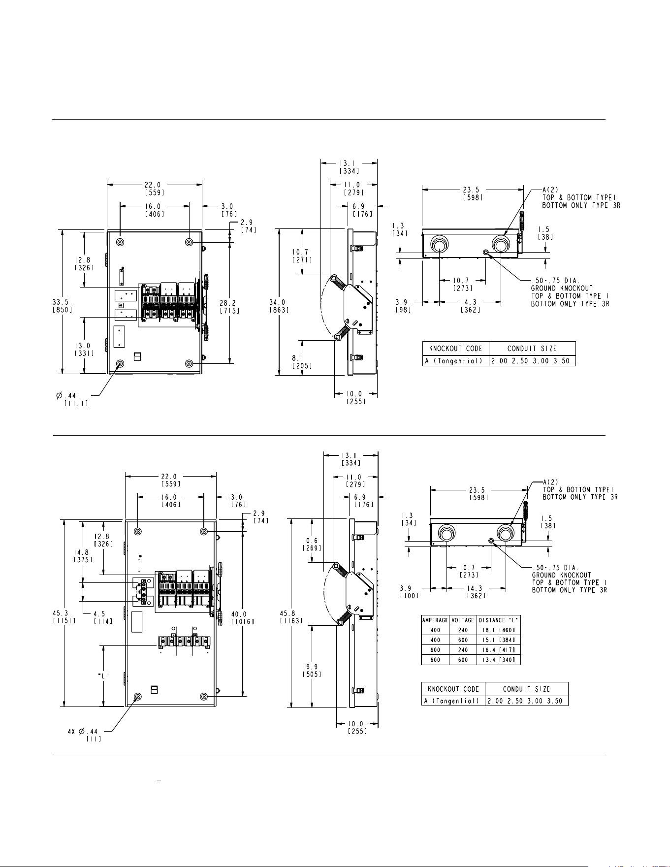
40 41
Detailed dimension drawings
Type 1 & 3R
400/600 Amp Heavy Duty Non-Fusible
Figure 19
No knockouts in the enclosures.
Dimensions shown in inches and millimeters [ ].
Dimensions shown accurate to
+
1/8 inch.
400/600 Amp Heavy Duty Fusible
Figure 20
No knockouts in the enclosures.
1) Enclosure dimensions unique for Type 4X and Type 12 switches at 400 and 600 Amps.
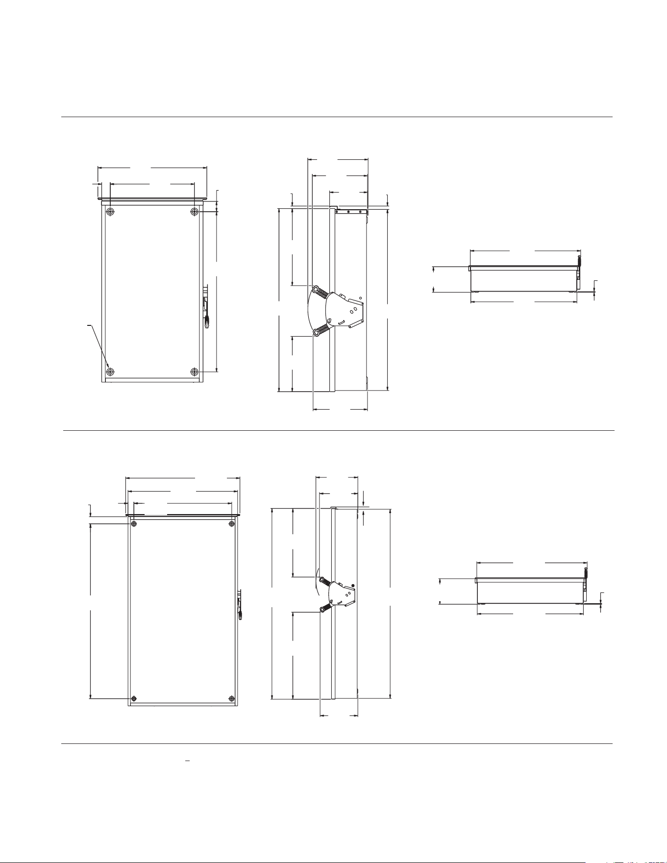
40 41
34.25
870[ ]
2.07
53[ ]
38.40
975[ ]
2.50
64[ ]
61.25
1556[ ]
39.96
39.50
1003[ ]
14.68
373[ ]
66.82
1697[ ]
24.02
610[ ]
30.46
774[ ]
13.24
336[ ]
13.44
341[ ]
66.25
1683[ ]
.83
[ 12
]
9.24
235[ ]
.25
6[ ]
38.40
975[ ]
1027[ ]
40.45
9.24
235[ ]
.25
6[ ]
38.40
975[ ]
1027[ ]
40.45
Type 3R (Outdoor)
800 / 1200 General and Heavy Duty Non-Fusible
800 / 1200 Amp Heavy Duty Fusible
3.20
81[ ]
32.00
813[ ]
40.25
1022[ ]
2.79
71[ ]
49.25
1251[ ]
.56 DIA (4)
14[ ]
14.68
373[ ]
13.44
341[ ]
24.02
610[ ]
18.46
469[ ]
13.25
337[ ]
54.67
1389[ ]
55.16
1401[ ]
.83
21[ ]
.54
14[ ]
9.57
243[ ]
Figure 21
Figure 22
No knockouts in the enclosures.
No knockouts in the enclosures.
Dimensions shown in inches and millimeters [ ].
Dimensions shown accurate to
+
1/8 inch.
66.67
[1693]
67.16
[1706]
9.29
[ 236 ]
40.49
[ 1028 ]
38.44
[ 976 ]
40.25
[ 1022 ]
38.44
[ 976 ]
32.00
[ 813 ]
3.20
[ 81 ]
2.79
[ 71 ]
40.49
[ 1028 ]
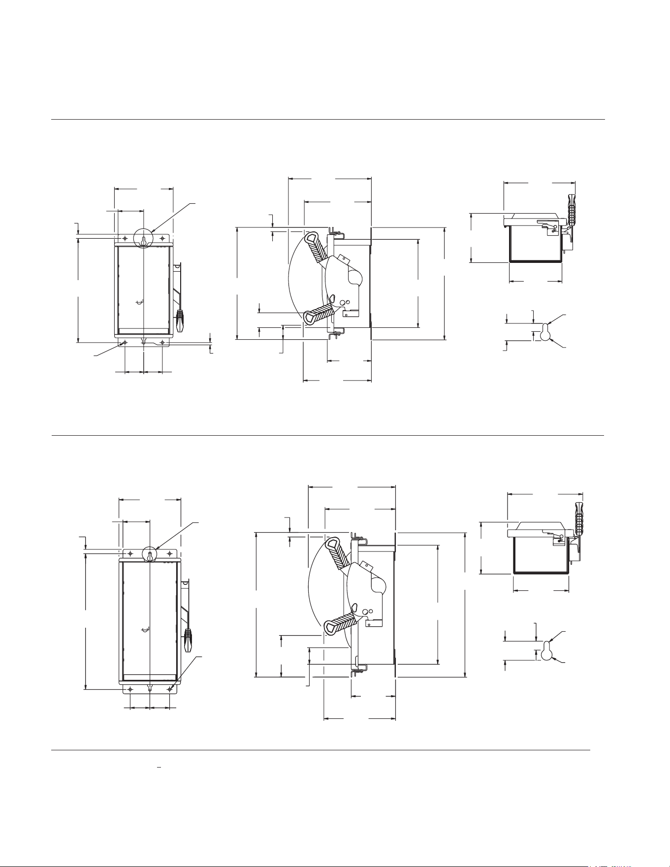
42 43
Detailed dimension drawings
41
Dimensions shown in inches and millimeters [ ].
Dimensions shown accurate to
+
1/8 inch.
Type 4X (Stainless); 12 (Industrial)
30 Amp Heavy Duty Non-Fusible
60 Amp Compact Heavy Duty Non-Fusible
30 Amp Heavy Duty Fusible
7.42
188[ ]
3.24
82[ ]
.42
11[ ]
13.33
338[ ]
2.75
70[ ]
2.75
70[ ]
72. )4( AID
8[ ]
.05
1[ ]
OF BOX
SEE DETAIL
A
6.65
169[ ]
6.22
158[ ]
9.02
229[ ]
.95
24[ ]
.35
9[ ]
36. AID
16[ ]
72. AID
7[ ]
DETAIL
A
11.12
282[ ]
5.56
141[ ]
8.59
218[ ]
1.81
46[ ]
1.86
47[ ]
14.14
359[ ]
8.46
215[ ]
.55
14[ ]
10.46
266[ ]
14.16
360[ ]
16.46
418[ ]
7.42
188[ ]
.42
11[ ]
2.75
70[ ]
2.75
70[ ]
3.24
82[ ]
SEE DETAIL
A
OF BOX
.27 DIA (4)
7[ ]
17.33
440[ ]
14.27
362[ ]
8.46
215[ ]
8.59
218[ ]
10.46
266[ ]
.55
14[ ]
5.32
135[ ]
17.31
440[
]
1.98
50[ ]
4.98
126[ ]
.35
36. AID
16[ ]
.95
24[ ]
72. AID
7[ ]
.35
9[ ]
DETAIL
A
6.22
158[ ]
6.65
169[ ]
9.02
229[ ]
Figure 23
Figure 24
No knockouts in the enclosures.
No knockouts in the enclosures.
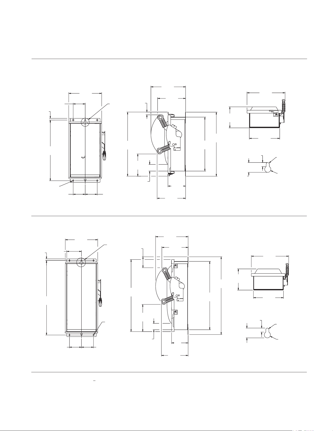
42 43
Type 4X (Stainless); 12 (Industrial)
60 Amp Heavy Duty
100 Amp Heavy Duty
18.47
469[ ]
.42
11[ ]
9.94
253[ ]
DIA (4)
.27
7
[ ]
3.62
92[ ]
SEE DETAIL
A
OF BOX
4.00
[ ]
102
4.00
[ ]
102
19.31
491[ ]
16.27
413[ ]
19.31
490[ ]
.83
21[ ]
8.45
215[ ]
8.59
218[ ]
5.33
135[ ]
1.99
51[ ]
10.46
266[ ]
6.69
170[ ]
.95
24[ ]
72. AID
7[ ]
26. AID
16[ ]
.35
9[ ]
DETAIL
A
11.47
291[ ]
6.34
161[ ]
9.17
233[ ]
10.43
265[ ]
24.16
[ ]
.42
11[ ]
4.74
120[ ]
SEE DETAIL
A
.27 DIA (4)
614
7[ ]
4.25
[ ]
108
4.25
[ ]
108
25.00
635[ ]
21.96
558[ ]
5.34
136[ ]
8.59
218[ ]
23.16
588[ ]
8.45
215[ ]
3.52
89[ ]
10.46
266[ ]
2.04
52[ ]
8.73
222[ ]
12.02
305[ ]
9.65
245[ ]
6.80
[ ]
173
.95
24[ ]
76. AID
17[ ]
72. AID
7[ ]
.35
9[ ]
DETAIL
A
Figure 25
Figure 26
No knockouts in the enclosures.
No knockouts in the enclosures.
Dimensions shown in inches and millimeters [ ].
Dimensions shown accurate to
+
1/8 inch.
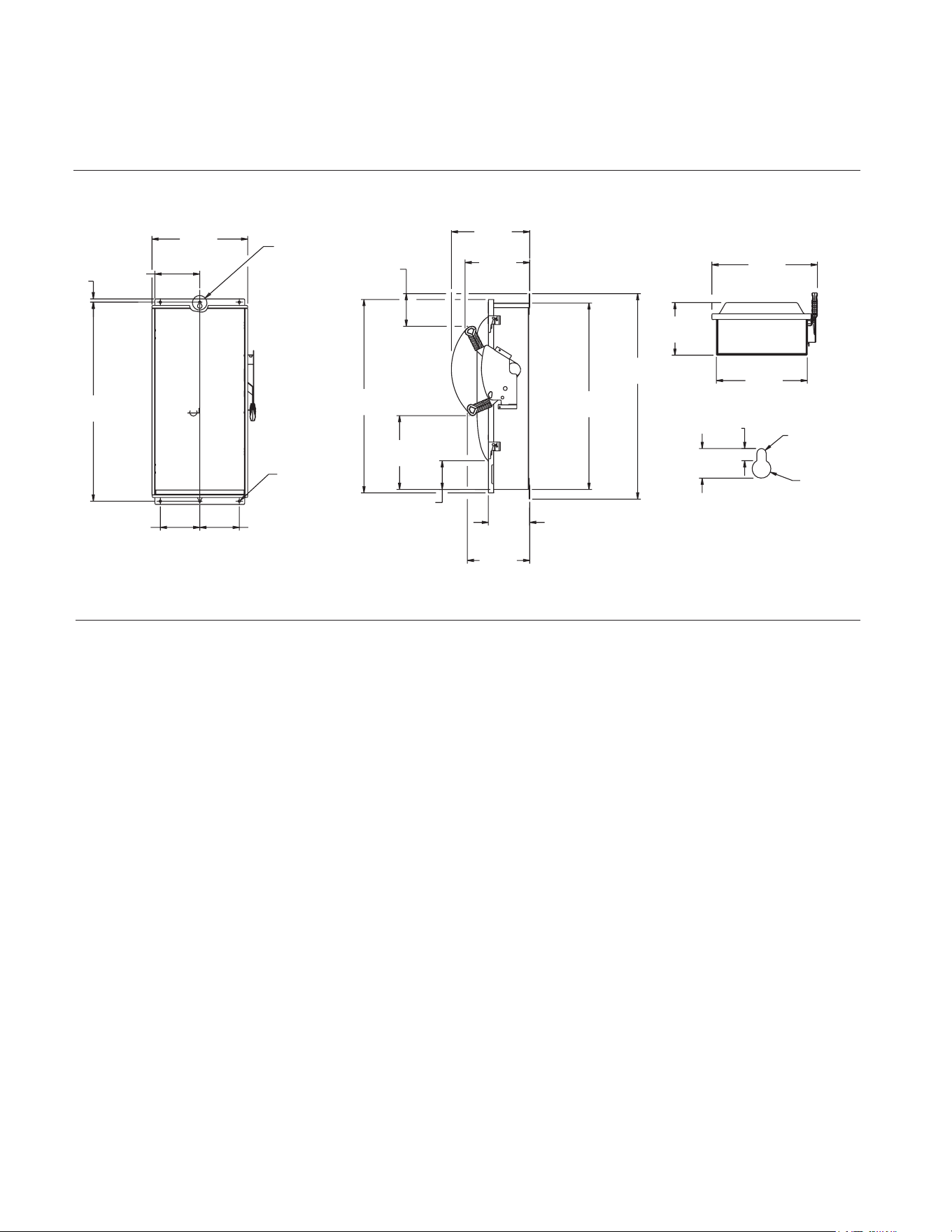
44 45
Detailed dimension drawings
Type 4X (Stainless); 12 (Industrial)
200 Amp Heavy Duty
6.75
171[ ]
6.75
171[ ]
.42
11[ ]
32.17
817[ ]
15.39
391[ ]
7.22
183[ ]
OF BOX
SEE DETAIL
A
.33 DIA (4)
9[ ]
33.00
838[ ]
10.01
254[ ]
10.37
263[ ]
5.24
133[ ]
29.96
761[ ]
31.07
789[ ]
6.63
168[ ]
4.60
117[ ]
12.58
319[ ]
11.86
301[ ]
16.95
431[ ]
8.45
215[ ]
14.62
371[ ]
57. AID
19[ ]
1.14
29[ ]
83. AID
10[ ]
.44
11[ ]
DETAIL
A
Figure 27
No knockouts in the enclosures.
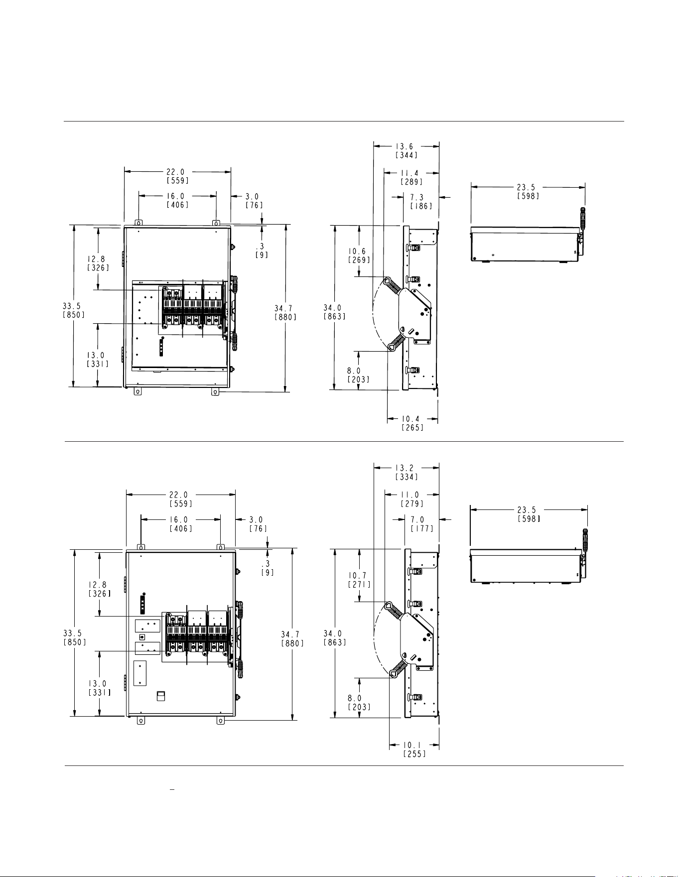
44 45
Type 4X (Stainless)
400/600 Amp Heavy Duty Non-Fusible
1
Figure 28
No knockouts in the enclosures.
Dimensions shown in inches and millimeters [ ].
Dimensions shown accurate to
+
1/8 inch.
Type 12 (Industrial)
400/600 Amp Heavy Duty Non-Fusible
1
Figure 29
No knockouts in the enclosures.
1) Enclosure dimensions unique for Type 4X and Type 12 switches at 400 and 600 Amps.
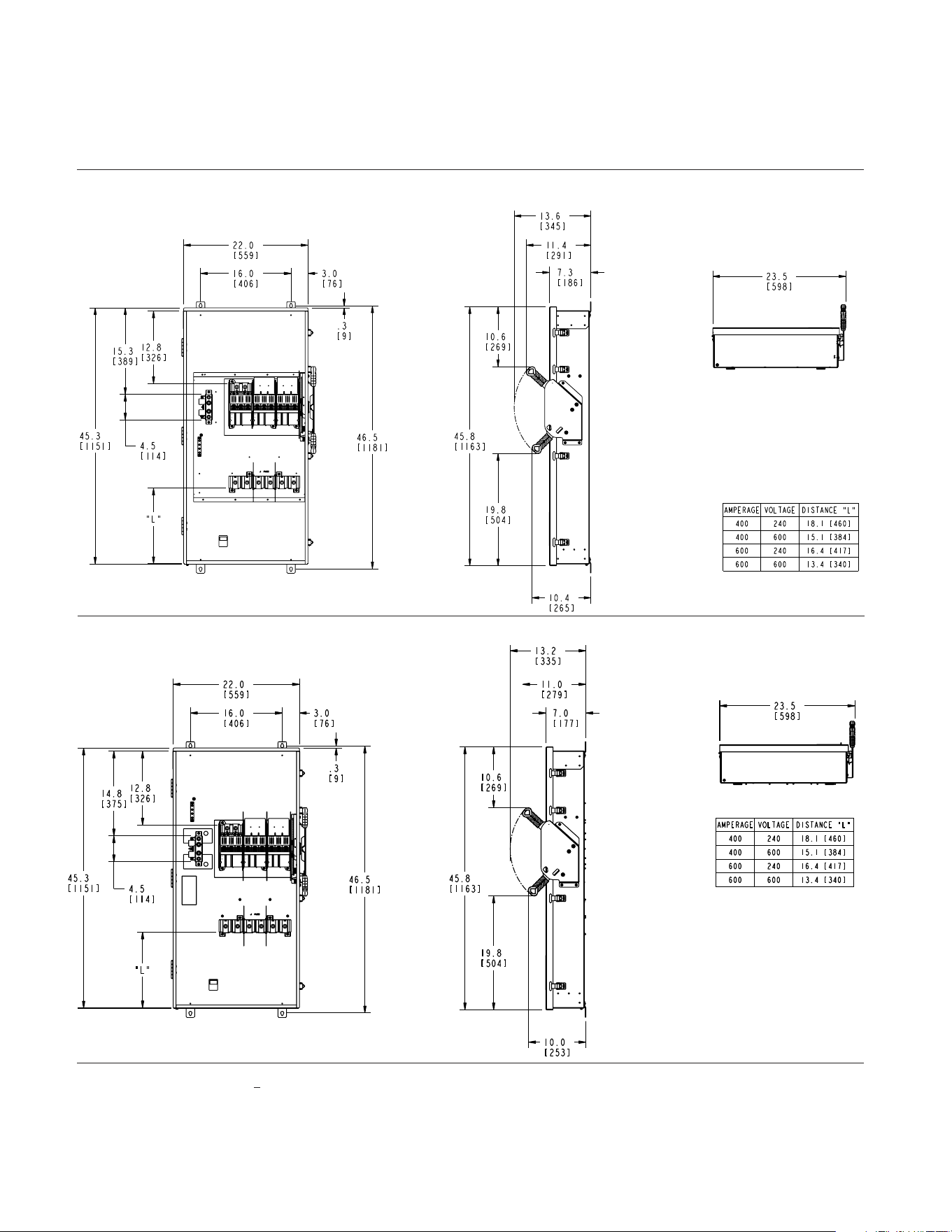
46 47
Detailed dimension drawings
Type 4X (Stainless)
400 / 600 Amp Heavy Duty Fusible
1
Type 12 (Industrial)
400 / 600 Amp Heavy Duty Fusible
1
Figure 30
Figure 31
No knockouts in the enclosures.
No knockouts in the enclosures.
Dimensions shown in inches and millimeters [ ].
Dimensions shown accurate to
+
1/8 inch.
1
Enclosure dimensions unique for Type 4X and Type 12 switches at 400 and 600 Amps.
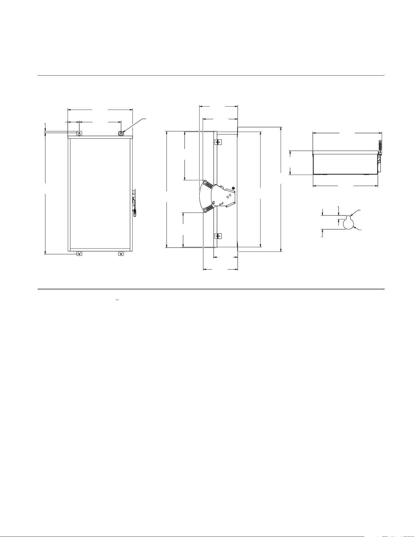
46 47
Detailed dimension drawings
47
14.68
373[ ]
58.56
1487[ ]
54.67
1389[ ]
9.24
235[ ]
13.24
336[ ]
18.46
469[ ]
55.16
1401[ ]
13.44
341[ ]
24.02
610[ ]
Type 4X (Stainless); 12 (Industrial)
800 / 1200 Amp Heavy Duty Non-Fusible
32.00
813[ ]
3.22
82[ ]
38.44
976[ ]
.78
20[ ]
57
1448[ ]
40
1016[ ]
SEE DETAIL
A
9
.29
236 ]
38.44
976[ ]
40
1016[ ]
1.40
36[ ]
.47
1[ 2
6 5. AI D
14[ ]
0 0 .1 AI D
25[ ]
DETAIL
A
]
Figure 32
No knockouts in the enclosures.
Dimensions shown in inches and millimeters [ ].
Dimensions shown accurate to
+
1/8 inch.
9.67
[ 246 ]
9.67
[ 246 ]
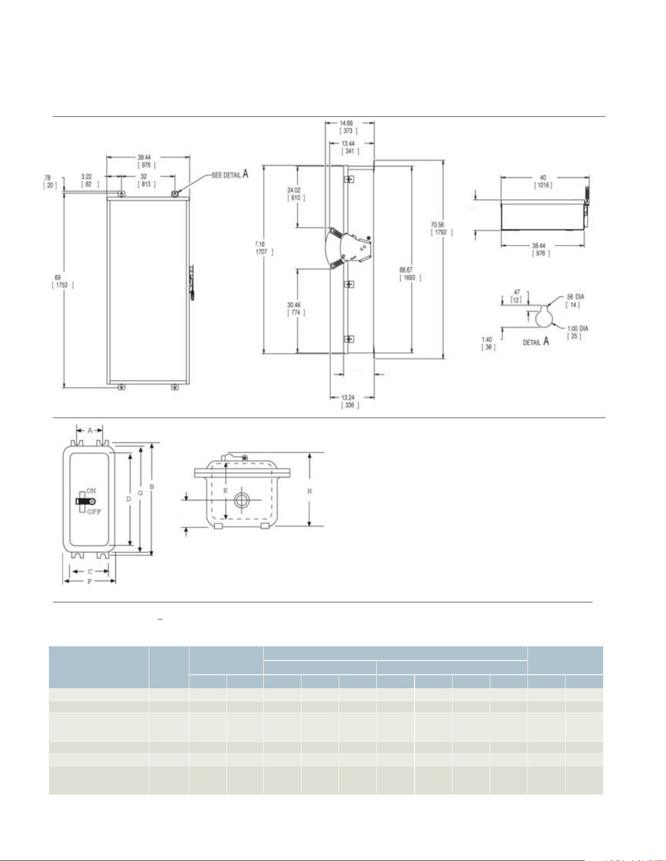
48 49
Dimensions shown in inches and millimeters [ ].
Dimensions shown accurate to
+
1/8 inch.
Type 4X (Stainless); 12 (Industrial)
800 / 1200 Amp Heavy Duty Fusible
Figure 32
No knockouts in the enclosures.
K
9.67
[ 246 ]
9.67
[ 246 ]
Types 7 and 9 (Figure 2)
Detailed dimension drawings
Figure 33
Types 7 and 9 (Figure 2)
Breaker Type
Catalog
Number
Mounting
Dimensions Command (inches)
Knockouts (4)
Conduit SizeInside Outside
A B C D E F G H K Std. Max.
ED2, ED4, ED6 EA
5 Z\x 13 Z\, 5 ZB\zn 10 C\v 5 M\zn 9 M\zn 14 Z\v 6 B\, 1 B\, 1 Z\v 1 Z\v
HED4, HED6 EB 6 18
6 Z\x
16
15 >\zn 9 M\, 19 C\, 6 ZZ\zn
2 2 2
FXD6, FD6, HFD6, HFXD6,
CFD6, JXD2(A), JXD6(A),
JD6, SJD6(A)
EC2
10 Z\v 22 B\, 11 C\v
20
6 Z\x 15 C\, 23 M\, 8 Z\v 2 C\v
2
2 Z\x
HJD6, HJXD6(A), HHJD6
EC4
10 Z\v 22 B\, 11C\v
20
6 Z\x 15 C\, 23 M\, 8 Z\v 2 C\v 2 Z\x
3
HHJXD6, SHJD6
EE
8 Z\x 27 Z\, 10 C\v 24 Z\, 7 C\v 13 M\, 27 Z\v 9 >\zn
4 3 4
LXD6(A), LD6(A), SLD6(A),
HLD6(A), HLXD6(A),
HHLD6, HHLXD6, SHLD6
ED6
11 M\, 40 C\v 13 C\, 37 M\, 7 M\, 18 Z\, 42 B\, 9 M\, 3 B\,
4 4
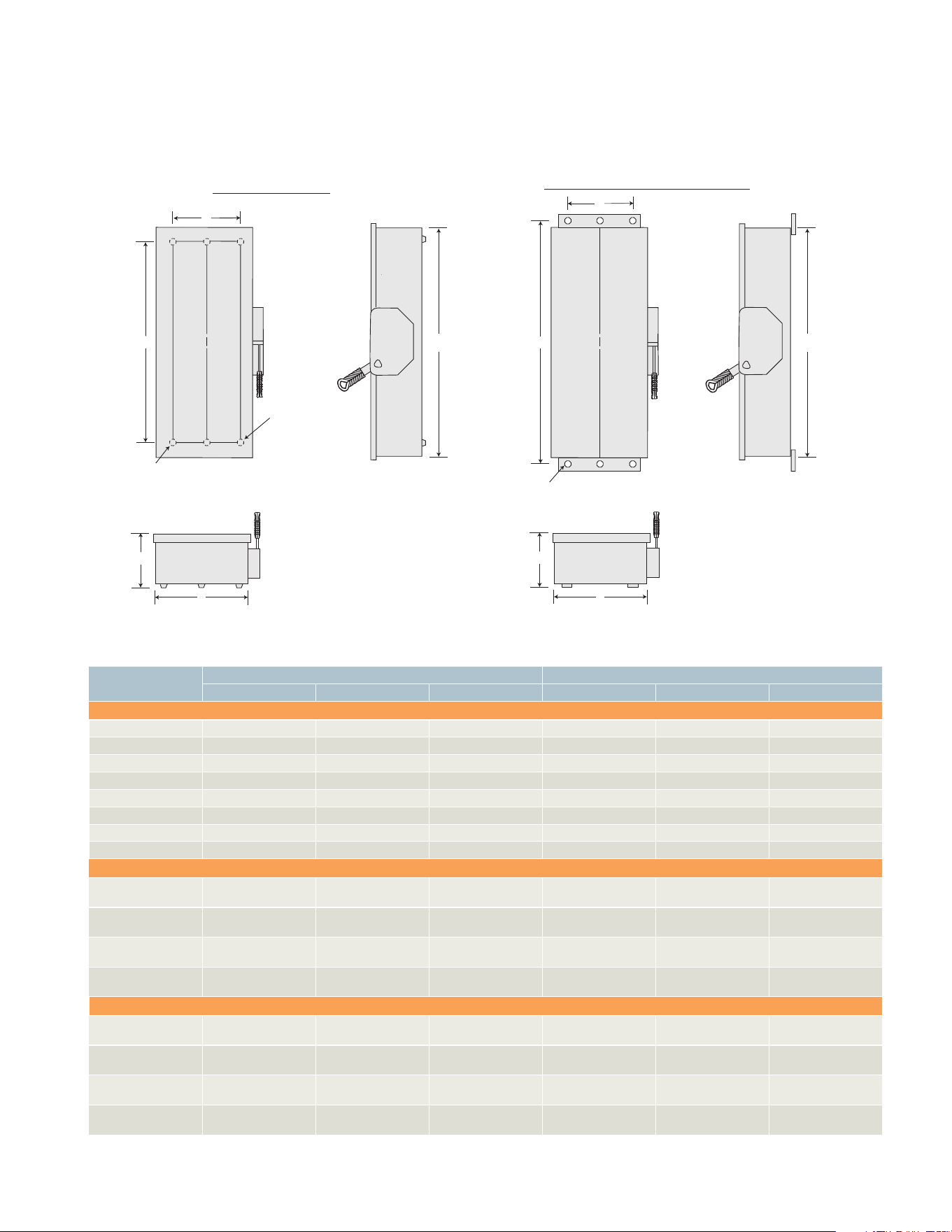
48 49
4 & 6 pole safety switch dimensions – inches (mm)
Catalog number
Enclosure Mounting
A B C D E F
Figure 1, 4-Pole Fusible and Non-fusible, Type 1
HNF461 24.50 (622) 9.53 (242) 6.09 (155) 19.00 (483) 6.75 (171) 0.268 (7)
HF461 29.12 (740) 9.53 (242) 6.09 (155) 23.50 (597) 6.75 (171) 0.268 (7)
HNF462 24.88 (632) 11.50 (292) 6.09 (155) 19.00 (483) 9.38 (238) 0.268 (7)
HF462 33.53 (852) 11.50 (292) 6.09 (155) 27.50 (699) 9.38 (238) 0.268 (7)
HNF463 27.62 (702) 12.18 (309) 6.09 (155) 19.36 (492) 8.00 (203) 0.268 (7)
HF463 36.44 (926) 12.18 (309) 6.09 (155) 28.11 (714) 8.00 (203) 0.268 (7)
HNF464 36.00 (914) 19.12 (486) 6.42 (163) 30.88 (784) 15.00 (381) 0.44 (11)
HF464 49.48 (1257) 19.12 (486) 6.42 (163) 45.50 (1130) 15.00 (381) 0.44 (11)
Figure 2, 4 & 6-Pole Fusible Type 12/3R and 4X
HF461J, HF661J,
HF661S
29.50 (622) 9.53 (242) 6.48 (165) 31.65 (804) 5.47 (139) 0.27 (7)
HF462J, HF662J,
HF662S
33.53 (852) 11.50 (292) 6.48 (165) 35.69 (907) 8.00 (203) 0.27 (7)
HF463J, HF663J,
HF663S
36.44 (926) 12.18 (309) 6.48 (165) 38.67 (982) 8.47 (215) 0.27 (7)
HF464J, HF664J,
HF664S
49.48 (1257) 19.12 (486) 6.78 (172) 51.64 (1312) 13.44 (341) 0.33 (8)
Figure 2, 4 & 6-Pole Non-fusible Type 12/3R and 4X
HNF461J, HNF661J,
HNF661S
24.50 (622) 9.53 (242) 6.48 (165) 26.65 (667) 5.47 (139) 0.27 (7)
HNF462J, HNF662J,
HNF662S
24.88 (632) 11.50 (292) 6.48 (165) 27.03 (687) 8.00 (203) 0.27 (7)
HNF463J, HNF663J,
HNF663S
27.54 (700) 12.18 (309) 6.48 (165) 29.77 (756) 8.47 (215) 0.27 (7)
HNF464J, HNF664J,
HNF664S
36.00 (914) 19.12 (486) 6.78 (172) 38.16 (969) 13.44 (341) 0.33 (8)
A
D
E
(6) “F“ Dia. mounting holes
C
L
This mounting hole
omitted on 30-100A,
4 pole Non-fusible
switches
Figure 1: Type 1
Figure 1: Type 12/3R and 4X
C
A
D
E
(6) ”F“ Dia. mounting holes (30-200A)
B
C
L
C
B
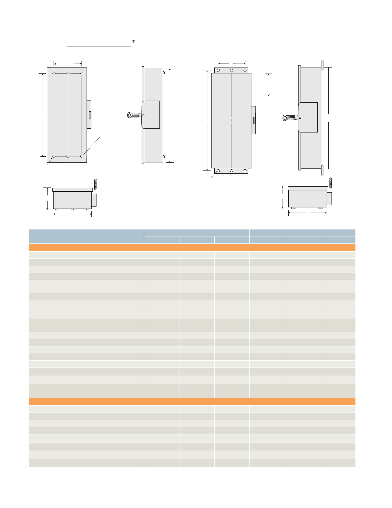
50 51
VBII design double throw dimensions – inches
Catalog number
Enclosure Mounting
A B C D E F
Figure 1 (30-1200A Type 1 & 3R)
DTNF221, DTNF321, DTNF361, DTNF361R 24.50 9.53 6.09 19.00 6.75 0.268
DTF321, DTF321R, DTF361 29.12 9.53 6.09 23.50 6.75 0.268
DTNF222, DTNF322, DTNF362, DTNF362R 24.88 11.50 6.09 19.00 9.38 0.268
DTF322, DTF322R, DTF362 33.45 11.50 6.09 27.50 9.38 0.268
DTNF223, DTNF323, DTNF323R, DTNF363, DTNF363R,
DTGNF223R, DTGNF223NR, DTGNF323R, DTGNF323NR
27.62 12.18 6.09 19.36 8.00 0.268
DTF323, DTF323R, DTF363, DTF363R 36.44 12.18 6.09 28.11 8.00 0.268
DTNF224, DTNF224R, DTNF324R, DTNF324,
DTNF364R,
DTGNF224R, DTGNF224NR, DTGNF324R, DTGNF324NR
36.00 19.12 6.42 31.00 15.00 0.44
DTF224, DTF224R, DTF324, DTF324R, DTF364,
DTF364R
49.44 19.12 6.42 44.50 15.00 0.44
DTF325, DTF326, DTF365 73.54 28.22 9.44 65.50 16.00 0.56
DTNF225, DTNF225R, DTNF325, DTNF365, DTNF365R 57.71 28.22 9.44 49.75 16.00 0.56
DTNF326, DTNF366, DTNF366R 57.71 28.22 9.44 49.75 16.00 0.56
DTNF327, DTNF367, DTNF367R 71.65 41.60 9.44 63.70 32.00 0.56
DTNF368, DTNF368R 71.65 41.60 9.44 63.70 32.00 0.56
NFR451DTK
3)
, NFR452DTK
3)
, NFR453DTK
3)
24.63 17.34 4.78 21.50
14.97
1)
0.27
1)
NF454DTK
2) 3
)
, NFR454DTK
2) 3)
37.25 19.19 6.32 33.50
16.00
2)
0.56
2)
NF455DTK
3)
, NF456DTK
3)
, NF457DTK
3)
NFR455DTK
3)
, NFR456DTK
3)
, NFR457DTK
3)
63.31 27.00 8.88 58.50
22.25
2)
0.56
2)
Figure 2 (30-200A Type 12 & 4X)
DTNF361J, DTNF361S 24.42 9.65 6.48 26.65 5.47 0.27
DTNF362J, DTNF362S 24.80 11.61 6.48 27.03 8.00 0.27
DTNF363J, DTNF363S 27.54 12.29 6.48 29.77 8.47 0.27
DTNF364J, DTNF364S 35.93 19.24 6.78 38.16 13.44 0.33
NF355HDTK
2)
, NF355SSDTK
2)
53.82 22.66 7.25 56.20 18.00 0.56
F353SSDTK
2) 3)
37.00 11.62 5.50 39.50 9.00 0.26
F354SSDTK
2) 3)
50.90 19.16 6.48 63.27 16.12 0.50
F355SSDTK
2) 3)
74.50 25.00 8.92 76.69 20.25 0.56
1)
(3) Mounting holes supplied (1 at top).
2)
(4) Mounting holes supplied.
3)
These switches are not Type VBII design.
4)
Drip hood not shown but provided on Type 3R enclosures.
Note: For inches/ millimeters conversion, multiply inches by 25.4.
Figure 1: Type 1 & 3R
Figure 2: Type 4X & 12
A
D
E
(6) ”F“ Dia. mounting holes (30-200A)
(4) ”F“ Dia. mounting holes (400-1200A)
C
L
C
B
This mounting hole
omitted on 30-100A
Type VBII Non-Fusible
switches
C
B
C
B
C
D
E
(6) ”F“ Dia. mounting holes (30-200A)
(4) ”F“ Dia. mounting holes (400-1200A)
C
L
A
50 51
Replacement parts
Ampere
rating
Line
base
Load
base
Handle/Handle guard
Mechanism
assembly LugsGeneral duty Heavy duty
30A General Duty 2- and 3-Pole Fusible and Non-fusible
5)
240V Max
30 Fused, 2-Pole W410472A – – – –
–
1)
30 Fused, 3-Pole W410473A – – – –
–
1)
30 Non-fused W410473B – – – –
–
1)
Fusible 2 and 3-Pole 60-600A General Duty & 30-600A Heavy Duty
5)
6)
240V Max
30 HD 240V
HFB21
2)
HBB21
2)
–
HH6123
7)
HM6123
7)
HL612
1)
60 GD
HFB612
2)
HBB612
2)
GH223 – HM6123
HL612
1)
60 HD 240V
6)
HFB22
2)
HBB22
2)
–
HH6123
7)
HM6123
7)
HL612
1)
100
HFB63
2)
HBB63
2)
GH223
HH6123
7)
HM6123
7)
HL63
1)
200
HFB64
2)
HBB64
2)
GH24
HH64
7
)
HM64
7)
HL64
1)
400
HFB65A
3) 6)
HBB65A
3) 6)
HH656A
HH656A
7)
HM656A
HL65678
4)
600
HFB66A
3) 6)
HBB66A
3) 6)
HH656A
HH656A
7)
HM656A
HL65678
4)
800
HFB67A
2) 6)
HBB67A
2) 6)
–
HH65678
7)
HM67A
HL67A
6)
9)
1200
HFB68
6)
HBB68
6)
–
HH68
7)
HM678
9)
Fusible 3-Pole Heavy Duty
5) 8)
600V Max
30 600V
HFB612
2)
HBB612
2)
–
HH6123
7)
HM6123
7)
HL612
1)
60 600V
HFB62
2)
HBB62
2)
–
HH6123
7)
HM6123
7)
HL612
1)
60A Oversized
HFB623
2)
HBB623
2)
– HH6123 HM6123 –
100
HFB63
2)
HBB63
2)
–
HH6123
7)
HM6123
7)
HL63
1)
200
HFB64
2)
HBB64
2)
–
HH64
7)
HM64
7)
HL64
1)
400
HFB65A
3) 6)
HBB65A
3) 6)
HH656A
HH656A
7)
HM656A
HL65678
4)
600
HFB66A
3) 6)
HBB66A
3) 6)
HH656A
HH656A
7)
HM656A
HL65678
4)
800
HFB67A
2) 6)
HBB67A
2) 6)
–
HH65678
7)
HM67A
HL67A
6)
9)
1200
HFB68
6)
HBB68
6)
–
HH68
7)
HM678
9)
Non-Fusible 3-Pole 60-600A General Duty and 30-600A Heavy Duty
5) 8)
600V Max
30 HD
HNB612
2)
– –
HH6123
7)
HM6123
7)
HL612
1)
60 GD
HNB612
2)
– GH223 – HM6123
HL612
1)
60 HD
10)
HNB623
2)
– –
HH6123
7)
HM6123
7)
HL612
1)
100
11)
HNB623
2)
– GH223
HH6123
7)
HM6123
7)
HL63
1)
200
HNB64
2)
– GH24
HH64
7)
HM64
7)
HL64
1)
400
HNB656A
3)
6)
– HH656A
HH656A
7)
HM656A
HL65678
4)
600
HNB656A
3)
6)
– HH656A
HH656A
7)
HM656A
HL65678
4)
800
HNB67A
2)
6)
– –
HH65678
7)
HM67A
HL67A
6)
9)
1200
HNB68
2)
6)
– –
HH68
7)
HM678
9)
1)
Three lugs included in kit.
7)
For type 4 / 4X stainless steel switches add “S” to end of catalog number.
2)
Includes lugs.
8)
For replacement door for heavy duty switches add “DOOR” to end of switch catalog number.
3)
Lugs are not included.
9)
Lugs included with line and load bases.
4)
One lug per kit.
10)
Also for oversized 30A HD switches.
5)
One per switch required unless otherwise noted.
11)
Also for oversized switch HNF362RL.
6)
One required per pole.
HBB612
HFB656
HNB623
HFB612
HM6123
HH6123

52 53
52 53
Fuse application and selection data
Siemens enclosed safety switches are
designed for fuse versatility. Although
Siemens is not a manufacturer of fuses,
once the type of fuse needed for a
particular application is determined, it’s
easy to select an appropriate switch.
The proper fuse type for the application
is selected using the following
parameters:
Voltage requirements
Conductor ampacity
Horsepower requirements
Maximum available RMS fault-current
UL fuse class when specified
The compatible fusible safety switch is
selected following these parameters:
System voltage requirements
Fuse amp ratings
Available fault current
UL fuse class
Environmental conditions
Number of poles required
One-Time Fuses
One-time fuses are standard for use in
situations calling for 1200 amperes or
less with maximum voltages for 250
or 600 volts. Specially designed,
current carrying links are connected
to contact pieces at the ends of the
enclosure. When an overload occurs,
the circuit quickly opens and the arc
is quenched by granular insulating
material that surrounds the current
carrying links.
Available in all classes.
Current Limiting Fuses
This design offers the highest degree of
circuit protection among fuses. Inside,
usually copper or silver alloy links are
embedded in pure quartz sand between
heavy copper end blocks. The special
design is fast-acting and interrupts
during the first half-cycle of a fault.
This causes a limitation of both
fault peak current and let-through
current.
Available in Classes J, L, R and T.
Dual-element Time-delay Fuses
Dual-element fuses may have time
delay designation since these fuses
employ two distinctly separate types
of elements. One provides overload
protection with time delay. (UL states
that time delay means having a
10-second operating delay at 500
percent of fuse label rating.) The
second provides short circuit protection
similar to a single-element fuse.
Dual-element fuses are most frequently
used on motor loads.
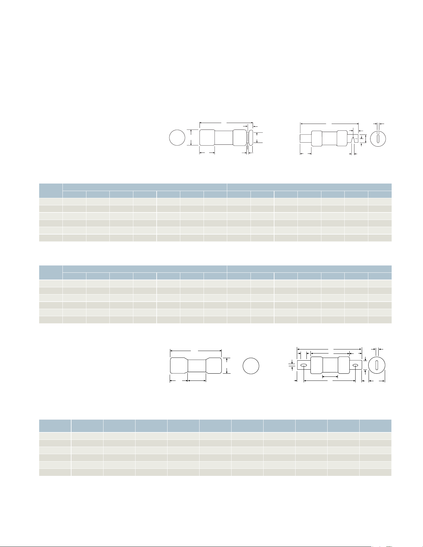
52 53
52 53
Fuse application and dimensions
Class R and H fuses
Class R application: Over-current and
short-circuit protection of motors and
transformers, service entrance equipment,
feeder and branch circuits.
(General Purpose Protection)
Class R rejection: A UL Class R fuse kit is
required that rejects lower-rated fuses
(H and K).
Class J fuses
Application: Current limiting protection
to a wide variety of applications,
Panelboards, Switchboards, Busway
and Feeder Circuits.
Rejection: Its unique dimensions
prevent the substitution of another fuse.
Class H fuse dimensions
Ampere
rating
250 Volts 600 Volts
A B C D E F G A B C D E F G
0-30 2 – – –
>\zn
–
Z\x
5 – – –
ZC\zn
–
ZM\cx
35-60 3 – – –
ZC\zn
–
XZ\cx 5 Z\x
– – –
1 Z\zn
–
XZ\cx
65-100
5 M\,
– – –
C\v Z\,
1
7 M\,
– – –
C\v Z\,
1
110-200
7 Z\,
– – –
1 Z\, C\zn 1 C\, 9 B\,
– – –
Z\, C\zn 1 C\,
225-400
8 B\,
– – –
1 B\, Z\v 1 M\, 11 B\,
– – –
1 B\, Z\v 1 M\,
450-600
10 C\,
– – – 2
Z\v 2 Z\v 13 C\,
– – – 2
Z\vx Z\v
Class J fuse dimensions
Ampere
rating A B C D E F G H J K
0-30
2 Z\v Z\x ZC\zn
– – – – – – –
31-60
2 C\, B\, 1 Z\zn
– – – – – – –
61-100
4 B\, 3 B\, 1 Z\, C\v Z\,
1
Z\x >\cx C\, 2 B\,
101-200
5 C\v 4 C\, 1 B\, 1 Z\, C\zn 1 C\, ZZ\zn >\cx C\,
3
201-400
7 Z\, 5 Z\v 2 Z\, 1 B\, Z\v 1 M\, ZB\zn ZC\cx ZM\cx 3 C\,
401-600 8 6
2 B\,
2
C\, 2 Z\,
1
ZM\cx ZZ\zn 3 C\v
Class R fuse dimensions
Ampere
Rating
250 Volts 600 Volts
A B C D E F G A B C D E F G
0-30 2
B\cx B\nv C\, >\zn
–
Z\x
5
C\zn C\cx B\, ZC\zn
–
ZM\cx
35-60 3
C\zn C\cx B\, ZC\zn
–
XZ\cx 5 Z\x Z\v C\cx M\, 1 Z\zn
–
XZ\cx
61-100
5 M\, Z\x >\cx XC\nv C\v Z\,
1
7 M\, Z\x >\cx XC\nv C\v Z\,
1
101-200
7 Z\, ZZ\zn >\cx CB\nv 1 Z\, C\zn 1 C\, 9 B\, ZZ\zn >\cx CB\nv 1 Z\, C\zn 1 C\,
201-400
8 B\, ZB\zn ZC\cx BZ\nv 1 B\, Z\v 1 M\, 11 B\, ZB\zn ZC\cx BZ\nv 1 B\, Z\v 1 M\,
401-600
10 C\, 1Z\, ZC\cx NC\nv
2
Z\v 2 Z\v 13 C\, 1 Z\, ZM\cx BC\nv
2
Z\v 2 Z\v
Ferrule type 0-60A
Class J Ferrule type 0-60A
Blade type 61-600A
Class J Blade type 61-600A
A
B
C
D
E
F
G
A
E
G
C
D
B
Ferrule Type 0-60A
Class J Blade Type 61-600A
Class J Ferrule Type 0-60A
Blade Type 61-600A
A
B
C
D
E
F
G
A
E
G
C
D
B
Ferrule Type 0-60A
Blade Type 61-600A
A
K
F
D
C
E
B
G
J
H
1” MIN
B
C
A
1” MIN
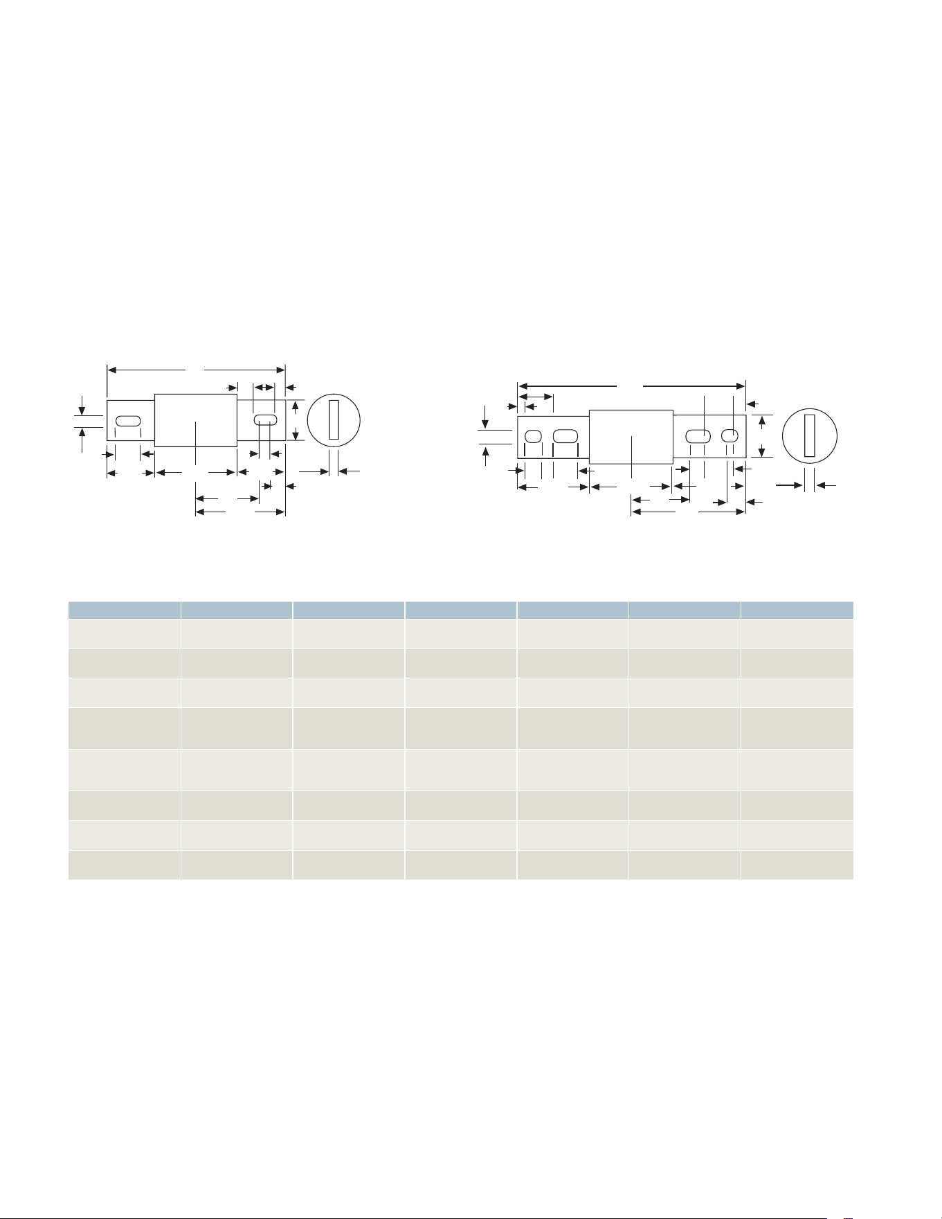
54 55
Class L
Application: Current limiting
protection for service entrance
equipment, feeder circuits and
metering centers.
Rejection: Its unique dimensions
prevent the substitution of
another fuse.
Class T
Application: It combines two highly
desirable features – a high degree
of current limitation and a small
physical size. Panelboards,
Switchboards and Metering Center.
Rejection: Its unique dimensions
prevents the substitution of
another fuse.
Class L Blade Type 601-800A Class L Blade type 801-1200A
Fuse Ratings
Class Amperes Volts Dimensions Int. Ratings I
2
t, Ip Circuits
H 1-600A 250 and 600V
or less AC
NEC
standards
10,000A Less than
10,000A available
General purpose
circuits
K5* 1-600A 250 and 600V
or less AC
Class H
without rejection
100,000A I
2
t - RK5 up to 100A
I
p
- RK5 up to 100A
Feeder
circuits
J 1-600A 600V or less Diff. from Class H 200,000A I
2
t - Low
I
p
- Low
Main & feeder
circuits
RK1 1/10-600A 600V or less
250V or less
Class H with
rejection feature
200,000A I
2
t - Slightly>J
I
p
- Slightly>J
Main & feeder
circuits (motor load
small percent)
RK5
(time
delay)
1/10-600A 600V or less
250V or less
Class H with
rejection feature
200,000A I
2
t - >RK-1
I
p
- RK-1
Motor starting
currents
T 1-1200A 300V AC Diff. from Class H 200,000A I
2
t - <J
I
p
- <J
Main & feeder
circuits
T 1-800A 600V AC Diff. from Class H 200,000A I
2
t - =J
I
p
- =J
Main & feeder
circuits
L 601-6000A 600V or less Bolt type 200,000A I
2
t - Low
I
p
- Low
Main & feeder
circuits
* Class K5 fuses do not prohibit the use of Class H type fuses in a switch.
10
3
/
4
1
13
/
32
5
/
8
5
/16
3
15
/32
1
1
/8
3
/4
3
13
/16
2
7
/
8
5
3
/
8
3
15
/
32
3
/
4
1
/8
3
/8
5
/
8
1
3
/
8
1
3
/8
1
/
2
8
5
/8
21
/32
15
/16
3
/
8
5
/8
1
1
/8
2
7
/16
3
13
/16
2
7
/16
1
/2
2
7
/
8
4
5
/16
8
5
/8
Fuse application and dimensions
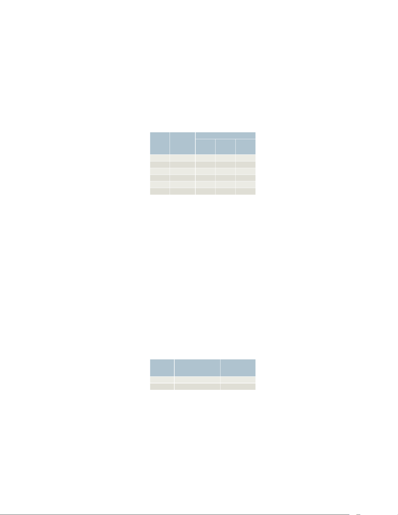
54 55
Type VBII Safety Switch
Ratings and test requirements
Enclosed switch load ratings
The primary functions of a fusible
enclosed switch are to carry current
continuously, to provide over current
and short-circuit protection, to
be capable of disconnecting the circuit,
and to provide means for mounting
fuses. Safety switches may also have
other capabilities covered by load break
ratings (in contrast with no-load
disconnect switches), such as standard
and maximum horsepower ratings
and the ability to withstand the
maximum I2t energy let-throughs
of fuses.
All Siemens safety switches are capable
of continuously carrying their full-rated
nameplate current at rated voltage.
This capability is directly attainable
in no-fuse switches and in fusible
switches when the fuses are replaced
with copper bars, without exceeding
permissible temperature rise.
Fuses are capable of carrying their
rated current in open air. Under this
condition the fuses will not open
and will not exceed permissible
temperature rise. When fuses are used
in a switch or other enclosure, a higher
ambient temperature is caused by the
switch heat and fuse-generated heat.
Since fuses are thermal acting by
design, they will not carry full current
rating at higher ambient temperatures.
To assist users of fusible equipment,
UL requires each fusible switch to carry
the statement “Continuous load current
not to exceed 80% of the rating of the
fuses employed.” Good electrical
practice may require even further
deratings depending on the type of
fuse, load, altitude and ambient
temperature of the switch location.
Load break ratings
All Siemens safety switches are
load break rated. The load break
rating is assigned by UL after the
switching unit has successfully
performed the following tests for
general use enclosed switches:
Load break ratings
12X current rating
In addition to the required UL overload
testing, all Siemens VBII Safety
Switches have been tested at twelve
times rated current at 600V AC to
assure compliance to automotive and
other heavy industry requirements.
Horsepower ratings
All Siemens safety switches, where
appropriate, are horsepower rated. The
assignment of such ratings is made by
UL only after the switching unit has
undergone tests to determine its
acceptability. In addition, the unit must
successfully perform on an overload
test series which includes repeated
interruption of the locked rotor current
of the motor for which it is to be rated
as follows:
Horsepower ratings
Most switches have two or more
ratings for a particular voltage and
current. Siemens safety switches are
UL listed for design E horsepower
ratings. With Siemens safety switches
no derating is required in most cases.
Depending on the switch and its
application, various ratings have been
achieved. All Siemens switches include
a complete list of the ratings on the
inside of the cover.
Horsepower rating charts
The number and variety of horsepower
ratings that can be applied to a
switching unit makes it impractical, in
most instances, to list all such ratings
on the front of the unit. Siemens does,
however, provide this data by means of
a chart on the inside cover.
Horsepower rating range
UL test procedure include ratings up to
500 HP. Siemens safety switch units in
appropriate sizes have successfully
passed the locked rotor current
interrupting test series for ratings
through 500 horsepower at both 480
and 600 volts AC and through 50
horsepower at 600 volts DC.
Maximum horsepower ratings
The maximum horsepower rating is
based upon the largest rating of a
time delay fuse: 1) which can be
incorporated in the switch and 2)
which will permit the motor to be
started. Since the fuse has extra time
delay, it can hold the starting current
of a larger motor longer than a
standard fuse.
Standard horsepower rating
This rating is assigned to a switch after
it has successfully completed the locked
rotor test series, on the basis of the
largest standard fuse rating: 1) which
can be incorporated in the switch and
2) which will permit the motor to be
started. The standard fuse does not
have a designed time delay to allow for
motor starting currents.
Switch
ampere
rating
Number of
ON, OFF
operations
per minute
Number of operations
With
current
Without
current Total
30-100 6 6000 4000 10000
200 5 6000 2000 8000
400 4 1000 5000 6000
600 3 1000 4000 5000
800 2 500 3000 3500
1200 1 500 2000 2500
Max HP
rating
Number of
ON, OFF Operations
per minute
Number of
cycles of
operation
100 6 50
500 1 10

56 57
56 57
Multiple-voltage
horsepower ratings
A switch may have additional standard
and maximum horse-power ratings
for different voltages. A switch that is
horsepower rated at 240V AC or 250V
DC may also have horsepower ratings
for motors on 120V AC or 125V DC
circuits.
Multi pole horsepower ratings
A switch may have horsepower ratings
applicable to the same current and
voltage ratings but with fewer poles
if the switch is investigated and found
suitable for the assigned rating.
Short-circuit withstandability
UL test procedures for switches and
fuses have been expanded to provide
realistic standards of performance
with respect to clearing high-level
fault currents.
These revised standards deal with the
control of destructive energy in the
shorted circuit. Two types of potential
damage are characteristic of high-level
short-circuits: mechanical and thermal.
Mechanical damage is caused by the
electromagnetic force surrounding
conductors; thermal damage is the
result of excessive current during
the fault-clearing time.
The UL fuse standard defines
maximum instantaneous peak
let-through current (lp) and maximum
destructive energy let-through (I
2
t)
for each fuse (except Class H).
Applications of fuses and safety
switches on systems having more
than 10,000A are available. Short
circuits require selections of the proper
UL-listed fuses and switches capable
of withstanding I
2
t let-throughs. See
chart below for withstand ratings on
Siemens switches.
I
2
t Rated
Suitability tests for service with
ClassH, R, J, L and T fuses have been
conducted. Representative switches
with test fuses connected in series
with each switch were subjected to
I
2
t let-through values in excess of
the capacities of the largest fuses
acceptable by the switches.
To pass the test, the switch must
remain operable after being
closed into a high-amp available
short-circuit current. The test fuse
is sized so that higher levels of
let-through current and energy will
be reached than would ever occur
during normal usage in the field.
See the chart below for I
2
t ratings
on Siemens switches.
Fuse rating Fuse class
Short circuit rating
(RMS symmetrical amperes)
General duty Heavy duty
Fusible Plug 10,000 —
H or circuit breaker 10,000 10,000
K 10,000 10,000
J 100,000 200,000
R 100,000 200,000
T 100,000 200,000
L — 200,000
Non-Fusible
1)
H or circuit breaker 10,000 10,000
K 10,000 10,000
J 100,000
200,000
2)
R 100,000
200,000
2)
L — 200,000
Switch rating ampere
I
2
t rating
(ampere squared
seconds)
I
p
rating
(amps)
30 50,000 14,000
60 200,000 26,000
100 500,000 32,000
200 2,000,000 50,000
400 6,000,000 75,000
600 12,000,000 100,000
800 10,000,000 80,000
1200 15,000,000 120,000
1)
With fuses or circuit breaker in series with switch. Fuse or circuit breaker
ampere rating cannot exceed switch ampere rating.
2)
60A compact switches are rated 100,000 with 60A max.
Class J or R fuses in series with switch.
Short-circuit withstand ratings I
2
t and I
p
ratings
Type VBII Safety Switch
Ratings and test requirements continued

56 57
56 57
Switch rating ampere
I
2
t rating
(ampere squared
seconds)
I
p
rating
(amps)
30 50,000 14,000
60 200,000 26,000
100 500,000 32,000
200 2,000,000 50,000
400 6,000,000 75,000
600 12,000,000 100,000
800 10,000,000 80,000
1200 15,000,000 120,000
A. GENERAL
1. TYPE
1.1. Switches shall be furnished as shown on the drawings
and shall be of the type described and specified herein.
2. STANDARDS
Switches shall comply with the following standards:
2.1 UL 98—Enclosed and Dead Front Switches
2.2 NEMA KS 1—Enclosed Switches
3. SUBMITTAL
3.1 Provide outline drawings with dimensions, conduit entry
exit locations, cable terminal sizes and equipment ratings for
voltage, amperage, horsepower and short-circuit. They also
must include replacement parts and accessories.
B. PRODUCT REQUIREMENTS
1. Switch Mechanism/Handle
1.1 Switch operating mechanism shall be nonteasible,
positive, quick-make, quick-break such that during normal
operation of the switch, the operation of the contacts shall
not be capable of being restrained by the operating handle
after the closing or opening action of the contacts has
started.
1.2 The operating handle shall be an integral part of the box
and not of the cover.
1.3 The handle position, combined with large ON and
OFF lettering on the nameplate, shall clearly indicate the
switch position.
1.4 The operating handle must be made of steel, with no
plastic parts other than the handle grip.
1.5 The operating handle shall be provided with a highly
visible red plastic grip and must allow for hook stick
operation.
1.6 The operating mechanism must be made of steel, with
no plastic parts.
1.7 All Heavy Duty switches (Type 1, 3R, 4/4X stainless steel,
4X non-metallic, 12) shall have a dual-cover interlock
mechanism to prevent unintentional opening of the switch
cover when the switch is ON and prevent turning the switch
ON when the cover is open. The cover interlock mechanism
shall have an externally operated override but the override
shall not permanently disable the interlock mechanism. The
tool used to override the cover interlock mechanism shall
not be required to enter the enclosure in order to override
the interlock.
1.8 30-200A 4X stainless steel switches shall have stainless
steel interior parts as standard.
1.9 All switches shall have provisions to accept up to three
5/16 inches hasp padlocks to lock the operating handle in
the OFF position.
2. SWITCH INTERIOR
2.1 All switches shall have switch blades that are visible
when the switch is OFF and the cover is open. (Type 1, 3R,
4/4X stainless steel, 4X non-metallic, 12).
2.2 Lugs shall be front removable and UL-listed for 60°C or
75°C conductors (30-100A), 75°C conductors (200-1200A)
aluminum or copper conductors. Except for 30A General
Duty line and load lugs shall be removable with no need to
remove line shields and arc suppressors.
2.3 30-100A Heavy Duty switches shall be capable of
accepting field installed fuse puller kits.
2.4 Optional copper body and crimp type lugs are to be
UL approved for field installation in Heavy Duty 30-1200A
ratings.
2.5 Heavy Duty Switches all shall have all-copper current
carrying parts other than standard aluminum alloy lugs.
2.6 All current-carrying parts shall be plated to resist corrosion.
2.7 Heavy Duty switches shall have provisions for field
installable auxiliary switches. There also must be low current
PLC type auxiliary interlock available for 30-200A switches.
2.8 All Heavy Duty switches shall have spring reinforced
fuse clips.
Type VBII Safety Switch
Suggested specifications

58 59
3. SWITCH ENCLOSURES
3.1 Switch covers shall be attached with pin-type hinges.
Except for outdoor General Duty 30A switches, top-hinged
doors are not acceptable.
3.2 Enclosures for Type 3R switches through 200A shall
have provisions for interchangeable bolt-on hubs in the top
endwall. Hubs shall be Siemens Type HS or HA hubs sized as
indicated on the plans.
3.3 Switches shall have wire-bending space and lug capacity
for one size larger Al/Cu wire than NEC and UL minimum
requirements.
3.4 The enclosure shall be finished with [gray baked polyester
paint which is electro deposited on cleaned, phosphate
pretreated steel (Type 1)], [gray baked polyester paint
which is electro deposited on cleaned, phosphate pre-treated
galvanized steel (Type 3R & 12)], [a brush finish on type 304
stainless steel (Type 4/4X stainless steel)].
3.5 All Heavy Duty switch enclosures shall have a formed
front flange to provide additional strength and rigidity.
3.6 Tangential knockouts shall be provided for switches rated
30-600A in Type 1 and 3R enclosures where permitted.
3.7 Cover latching means for Type 4/4X & 12 rated through
1200A shall be quick-release, lift-lever type.
3.8 Type 12 enclosures shall be dual rated as Type 3S to allow
their use in outdoor applications.
3.9 Cover viewing window shall be an available option on
30-400A NEMA 12 and 4/4X stainless steel switches. The
window must allow viewing of both visible blades when the
switch is OFF and viewing of indicating fuses in 30-200A
ratings.
3.10 All Heavy Duty switches shall have metal nameplates,
except for non-metallic switches, which must have
plastic nameplates.
4. SWITCH RATINGS
4.1 All switches shall be UL-listed.
4.2 30-200A Heavy Duty switches shall also be horsepower
rated for AC and/or DC as indicated on the plans.
4.3 Switches shall be horsepower rated for design E motors
on internal labeling.
4.4 The Heavy Duty switch UL-listed short-circuit current
rating shall be: [10,000 RMS symmetrical amperes when used
with or protected by Class H or K fuses (30-600 amperes)]
[200,000 RMS symmetrical amperes when used with or
protected by Class R or Class J fuses (30-600 ampere switches
employing appropriate fuse rejection schemes)]. [200,000
RMS symmetrical amperes when used with or protected by
Class L fuses (800-1200 amperes)].
4.5 All switches intended for service entrance shall be UL
approved for this application.
4.6 All Heavy Duty switches shall be I
2
t rated.
C. APPROVED MANUFACTURERS
1.1 Switches shall be manufactured by Siemens (no equal) or
approved equal.
Type VBII Safety Switch
Suggested specifications continued
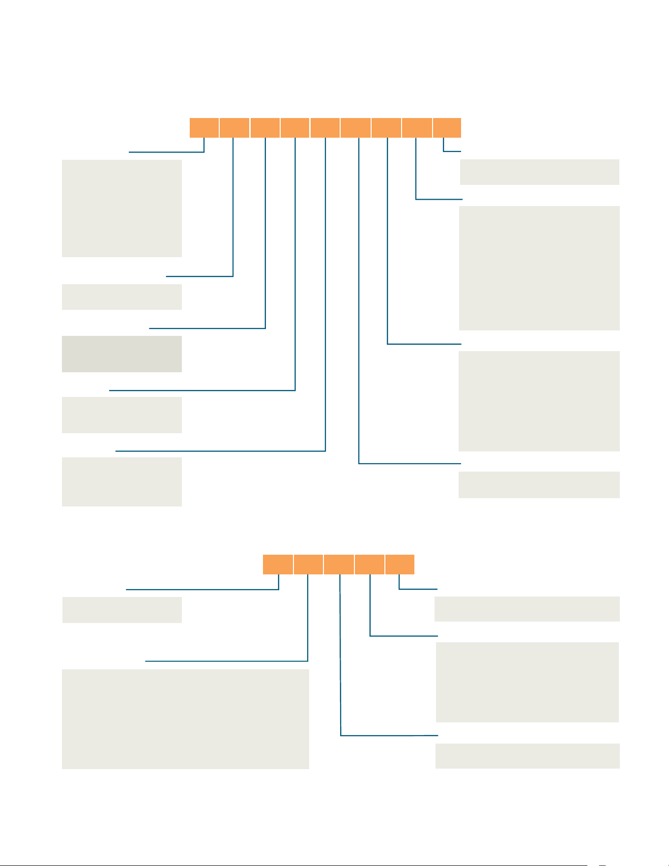
58 59
Type VBII Safety Switch
Catalog numbering system
Switch type
L = General Duty
10k AIC Max.
(Plug Fused
& 60A Max
Non-Fused)
G = General Duty
H = Heavy Duty
DT = Double Throw
DTG = General Duty DT
Fused or non-fused
F = Fused
NF = Non-Fused
Number of poles
1 = 1
2 = 2
3 = 3
Voltage
1 = 120V or 120/240V
2 = 240V
6 = 600V
Special applications with:
CH = Crouse Hines Receptacle
CJ = Factory J Fuse Spacings
CR = Class R Clips Installed
CU = Factory Installed Copper Lugs
G = Factory Installed Ground Bar
H = Height or Size Reduced
L = Oversized Enclosure
PN = Pyle National Receptacle
PV = Photovoltaic rated
PVPG = Photovoltaic rated, Positive Ground
W = Viewing Window
Enclosure type
Omit = Type 1, Indoor
R = Type 3R, Outdoor
S = Type 4/4X, Stainless Steel
SS = Type 4/4X, 316 Grade
Stainless Steel
X = Type 4/4X, Non-Metallic
J = Type 12, Industrial
XL = Type 4/4X, Non-Metallic,
Less Line & Load Lugs
With or without neutral
Omit = Less Neutral
N = With Neutral
Amperes
1 = 30A
2 = 60A
3 = 100A
4 = 200A
5 = 400A
6 = 600A
7 = 800A
8 = 1200A
4 = 4
6 = 6
Series type
A = 400A, 600A
Omit = 30A-200A, 800A-1200A
Note: Catalog numbering systems above do not apply to 4-pole & Type “F” & “FR” double throw switches and accessories.
1)
For 400A, 600A use 680V max accessories except for T Fuse Kit.
2)
Only offered for 400A, 600A.
3)
For 30A-200A, 800A-1200A.
Switch type
H = Heavy Duty
G = General Duty
3)
Accessory type
A1 = Auxiliary Switch 1/NO & 1/NC
A2 = Auxiliary Switch 2/NO & 2/NC
A3 = Auxiliary Switch Low Current
CL = Compression Lug Barrier/
Mounting Kit
CU = Copper Lug
3)
G = Ground Lug Kit
G2 = Insulated Ground Lug Kit
J = Class J Fuse Kit
2)
LC
= Copper Lug Kit
3)
N = Neutral
N2 = 200% Neutral
3)
NCM = Field Replacement
Lug Kit
2)
P = Fuse Puller Kit
R = Class R - Fuse Clip Kit
T = Class T - Fuse Kit
Amperes
1 = 30A
2 = 60A
12 = 30/60A
3 = 100A
23 = 60/100A
123 = 30/60/100A
1234 = 30/60/100/200A
4 = 200A
5 = 400A
56 = 400/600A
5678 = 400/600/
800/1200A
6 = 600A
78 = 800/1200A
Maximum voltage
2 = 240V Max
1)
6 = 600V Max
Series type
A = 400A, 600A
Omit = 30A-200A, 800A-1200A
Accessories catalog numbering system
H F 3 6 4 N R CU A
H R 6 4 A

Published by
Siemens Industry, Inc. 2018.
Siemens Industry, Inc.
5400 Triangle Parkway
Norcross, GA 30092
For more information, please contact
our Customer Support Center.
Phone: 1-800-241-4453
E-mail: inf[email protected]
usa.siemens.com/switches
Order No.: SSSA-SB03A-0118 BA
Printed in U.S.A.
© 2018 Siemens Industry, Inc.
The technical data presented in this document is based on an actual case
or on as-designed parameters, and therefore should not be relied upon for
any specific application and does not constitute a performance guarantee
for any projects. Actual results are dependent on variable conditions.
Accordingly, Siemens does not make representations, warranties, or
assurances as to the accuracy, currency or completeness of the content
contained herein. If requested, we will provide specific technical data or
specifications with respect to any customer’s particular applications. Our
company is constantly involved in engineering and development. For that
reason, we reserve the right to modify, at any time, the technology and
product specifications contained herein.