usa.siemens.com/sdv7
SDV7
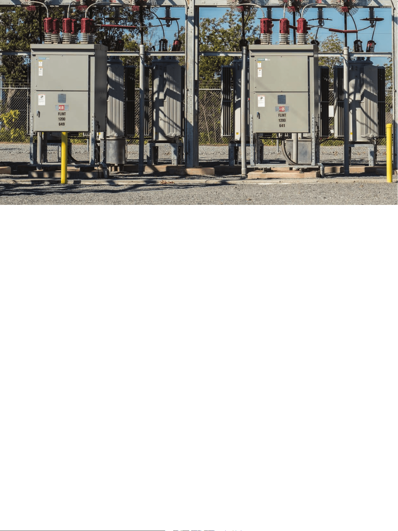
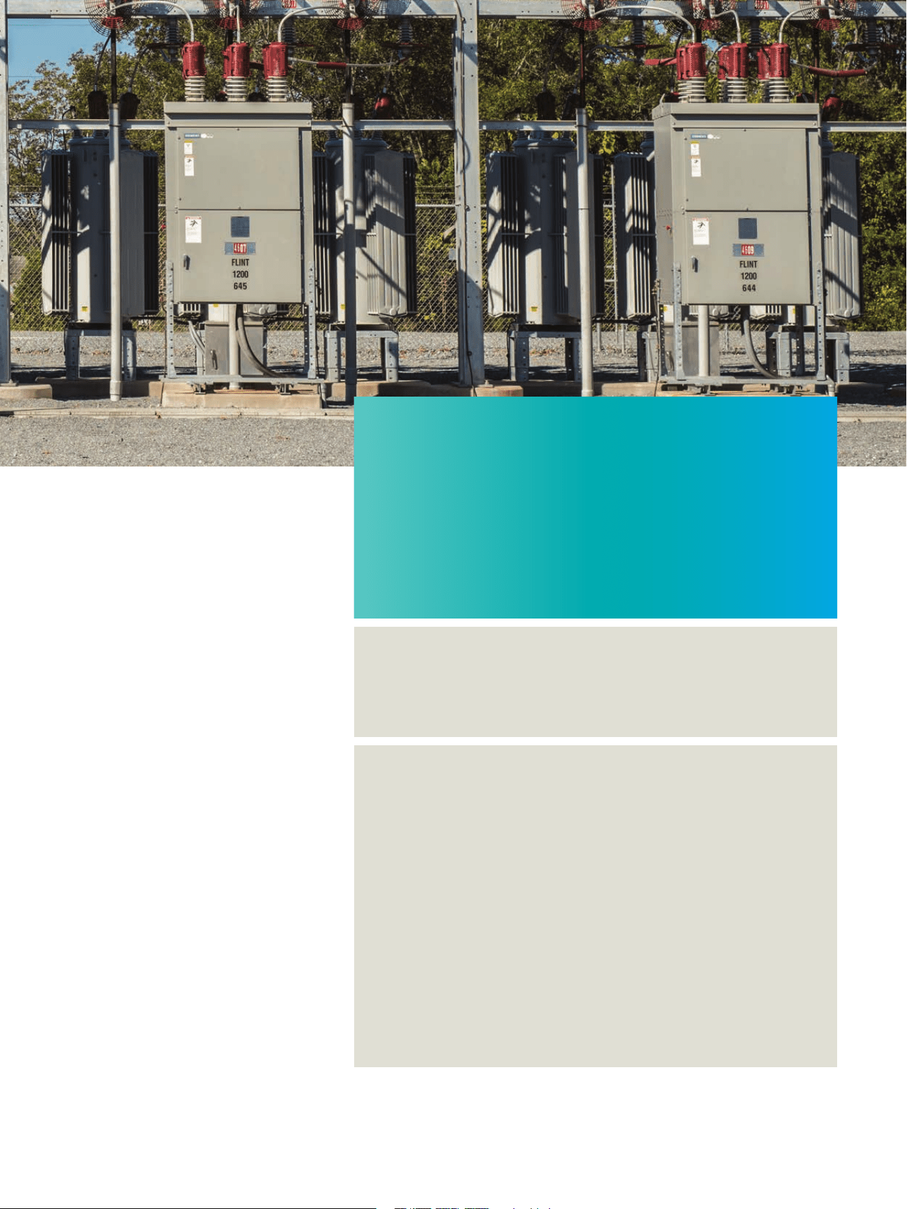
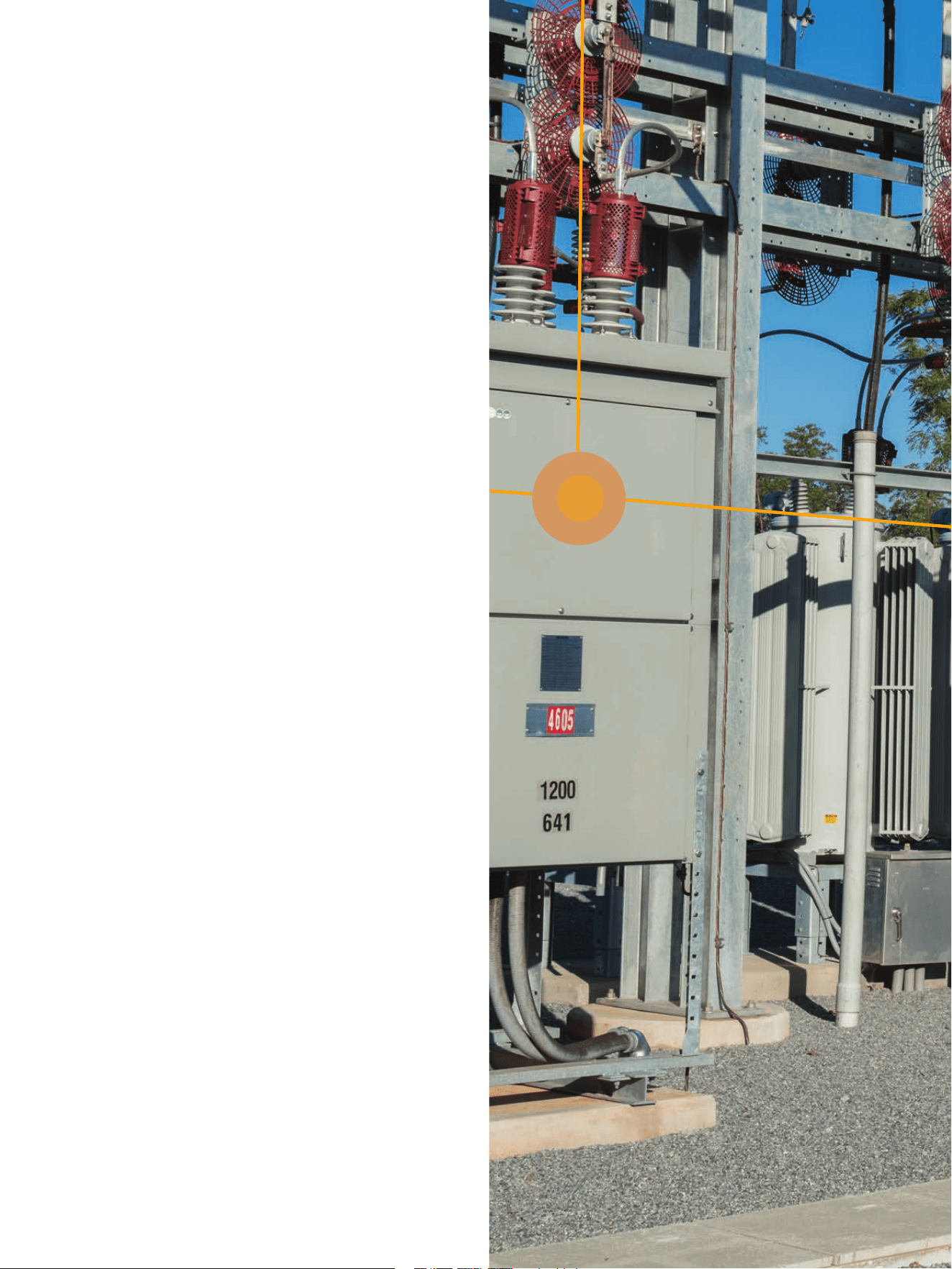
Outdoor distribution circuit
breaker family
15.5 kV to 38.0 kV
01010011 01000100 01010110 00110111 00100000
01010011 01000100 01010110 00110111 00100000
01010011 01000100 01010110 00110111 00100000
01010011 01000100 01010110 00110111 00100000
2
SDV7 | Brochure
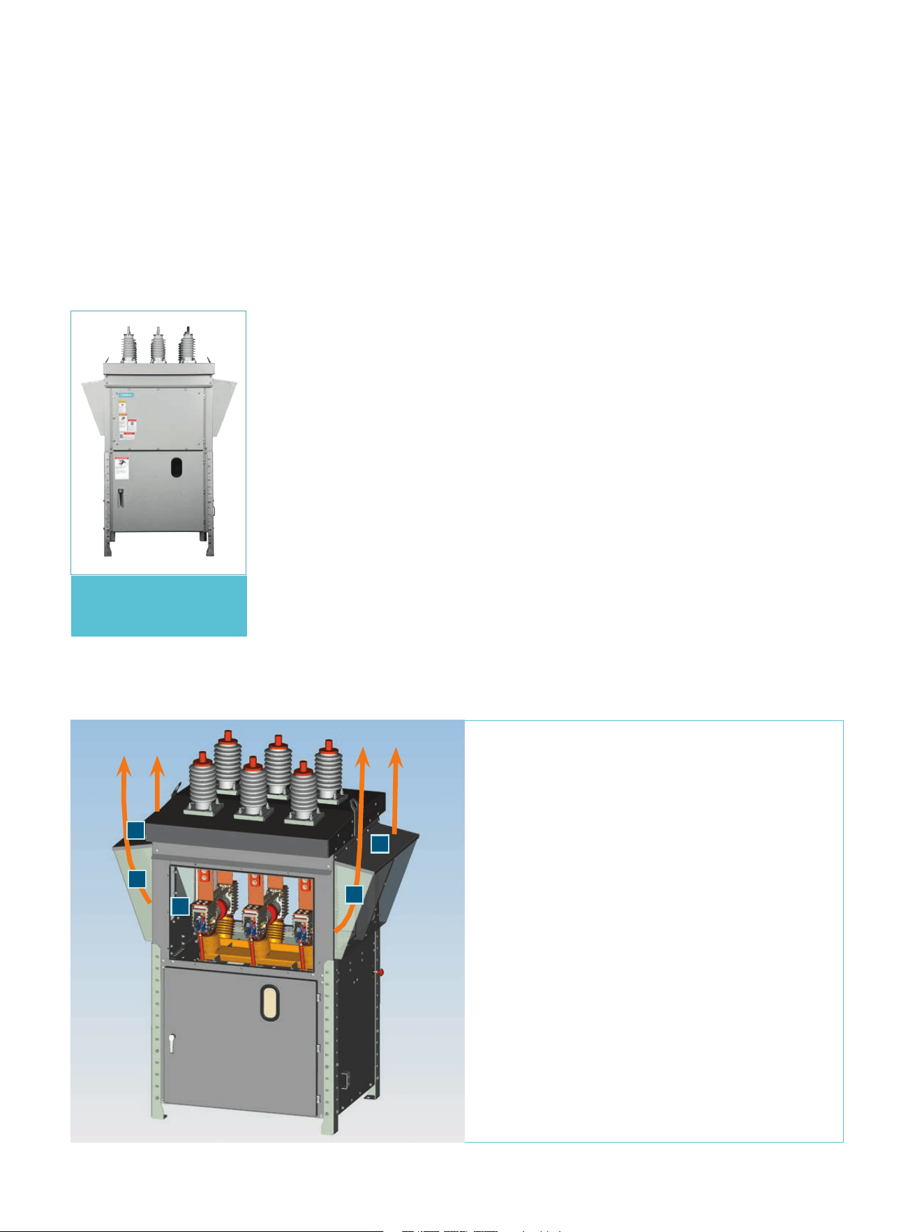
The type SDV7 family is the latest
generation of the successful type
SDV product line.
With over 10,000 type SDV circuit breakers and 350,000 type 3AH
operators in service, you can rely on Siemens.
Ratings have been expanded, an option for a magnetic-actuator to
the standard stored-energy operator has been introduced, and an
arc-resistant option tested to ANSI/IEEE C37.20.7 type 2B.
Table of contents
Introduction 04
Vacuum interrupters, simple current path, low-maintenance 05
requirements, and enclosure
Type 3AH35-SE stored-energy operator 06 – 07
Type 3AH35-MA magnetic-actuator operator 08 – 11
Arc-resistant enclosure option 12
Technical ratings, dimensions and features and benefits 13 – 15
3
Brochure | SDV7

Introduction
The type SDV7 family is the latest
generation of the successful type SDV
product line.
Ratings have been expanded, along with
introduction of an option for a magnetic-
actuator operator, as an alternate to the
standard stored-energy operator. An option
for arc-resistant construction, tested to
ANSI/IEEE C37.20.7 requirements for
accessibility type 2B, is also available.
The magnetic actuator is adapted to the
basic high-voltage support structure of the
type SDV7 stored-energy operator version.
The magnetic-actuator design has been
qualified with full short-circuit tests to the
same performance levels as with the stored-
energy operator design.
The type 3AH35-MA magnetic actuator
operator employs long-life, rare-earth
permanent magnets to provide the closing
force needed for the worst-case closing and
latching duty, in combination with the basic
kinematic structure used with the entire
type SDV7 family for opening operations.
The magnetic actuator employs an
electronic controller to provide power to
close the circuit breaker, as well as to supply
the energy to open the circuit breaker.
The type 3AH35-SE stored-energy operator
is derived from the highly reliable type 3AH
family of operators, with over 30 years of
design heritage.
With over 10,000 type SDV circuit breakers
and 350,000 type 3AH operators in service,
you can rely on Siemens products to meet
your distribution system demands.
The type SDV7 family now includes an
option for arc-resistant construction. The
arc-resistant enclosure has been tested for
conditions of internal arcing in accordance
with ANSI/IEEE C37.20.7, for accessibility
type 2B. The arc-resistant design shares the
same footprint dimensions as the non-arc-
resistant design, for ease in application.
The design of the type SDV7 features
significant reduction in enclosure size; and,
consequently, in the overall footprint. The
type SDV7 product line encompasses the
voltage groups 15.5 kV, 27.6 kV and
38.0 kV. Each group is specifically designed
to optimize space and material for the
voltage class while retaining common
features across the entire product line.
Introduction
The type SDV7 family is the latest generation of the
successful type SDV product line
Ratings availability
Rating
Non-arc-
resistant
Arc-resistant
Stored-
energy
operator
Magnetic-
actuator
operator
15.5 kV; 20 kA/25 kA; 1,200 A/2,000 A Available Available Available Available
15.5 kV; 31.5 kA/40 kA;
1,200 A/2,000 A/3,000 A
Available Available Available Future
27.6 kV; 20 kA/25 kA; 1,200 A/2,000 A Available Available Available Available
38.0 kV; 20 kA/25 kA; 1,200 A/2,000 A Available Available Available Future
38.0 kV; 31.5 kA/40 kA;
1,200 A/2,000 A/2,500 A
Available Available Available Future
4
SDV7 | Brochure
Vacuum interrupters
The heart of the medium-voltage circuit
breaker is the time-proven Siemens vacuum
interrupter. Siemens vacuum interrupters
use chrome-copper contact material, which
keeps the chopping current to five amperes
or less and thereby keeps overvoltages to a
minimum.
The contact configuration employs axial-
magnetic field geometry to maintain the arc
in diffuse mode and minimize contact
erosion, and provide a capability of up to
100 full-rated fault interruptions (depending
on rating) before replacement is necessary.
A contact-wear indicator is provided to
directly determine the wear of the contacts
within the vacuum interrupter.
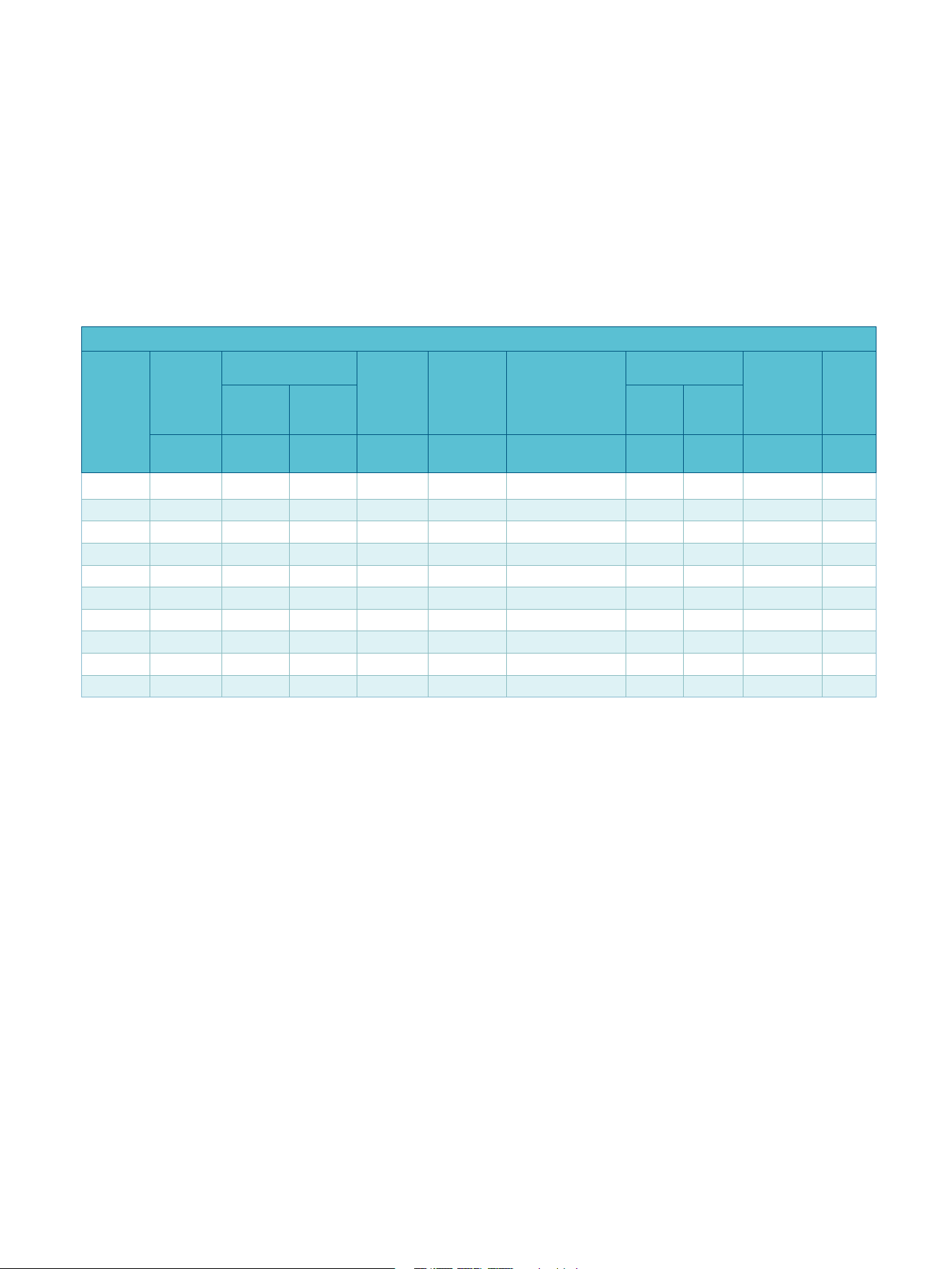
Simple current path
The type SDV7 configuration is extremely
simple. The vacuum interrupters are located
so that the connections between bushings
and vacuum interrupters are short and
direct. The current path uses a flexible shunt
connection between the vacuum interrupter
moving contact and the adjacent bushing
terminal, rather than using sliding contacts
or other moving elements in the current
circuit.
The type SDV7 distribution circuit breaker
enclosure includes bolted, hinged doors on
the front and rear of the high-voltage
compartment, as well as hinged, latched
doors for the operator compartment as well
as the relay and control compartment.
Access to internal components, whether
high voltage or low voltage, is very
convenient.
Low-maintenance requirements
The vacuum interrupter is a sealed unit so
the only maintenance typically required on
the interrupter is to remove contaminants
and check the vacuum integrity. The
vacuum interrupters can be disconnected
from the operating mechanism quickly,
without tools, to check vacuum integrity.
Other maintenance requirements on the
circuit breaker include lubrication of moving
parts and cleaning of insulation, at
recommended intervals of five years or
10,000 operations.
Enclosure
The configuration of the circuit breaker is
very compact, resulting in a small footprint,
allowing the SDV7 circuit breaker to fit into
many existing installations that earlier
design circuit breakers could not.
The enclosure is robust, with the adjustable
legs located at the corners of the enclosure
rather than recessed under the enclosure.
Ground pads are stainless steel pads welded
on diagonally opposite corners of the
enclosure, a better arrangement than
designs that incorporate the ground pads
into removable legs. All exterior hardware,
hinges, and latches are stainless steel for
long life.
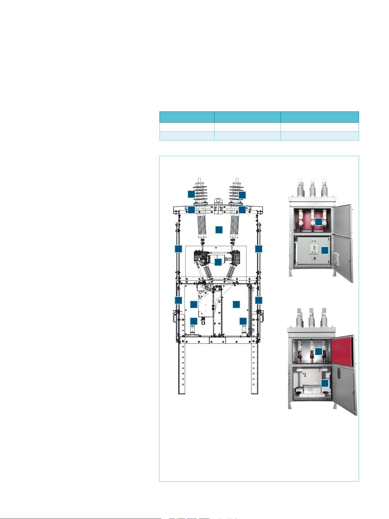
Section view
1. Bushings
2. Current transformers
3. High-voltage compartment
4. Access door (bolted)
5. Vacuum interrupters
6. Access door (latched)
7. Relay and contol compartment
8. Operator compartment
9. Ground pads (opposite corners)
1
2
3
4
5
9
6
7
1
2
4
6
9
8
Relay and control
compartment side
Operator
compartment side
Enclosure type Stored-energy operator Magnetic-actuator operator
Non-arc-resistant SDV7-SE SDV7-MA
Arc-resistant SDV7-SE-AR SDV7-MA-AR
3
7
3
8
5
Brochure | SDV7
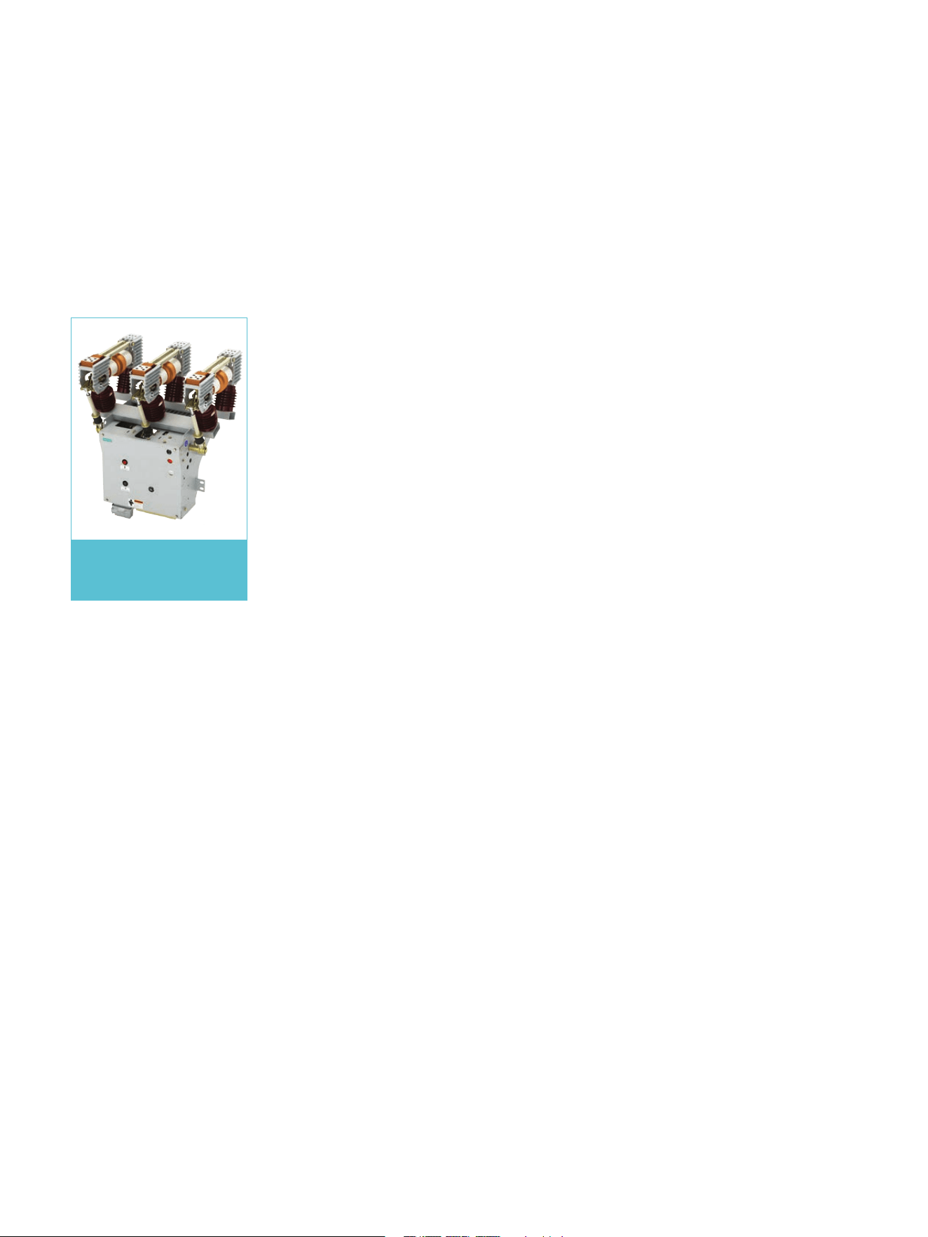
Type 3AH35-SE stored-energy operator
The type 3AH35-SE circuit breaker operator
is a durable and reliable stored-energy
mechanism. This operator is designed to
perform up to 10,000 operations before
overhaul, and the basic operator in the 3A
family has a mean time before failure
(MTBF) of over 23,000 years (as of 2014).
The type 3A operator family has over
1,000,000 units in service worldwide in
vacuum circuit breakers. Over 120,000 type
3AH3 operators are in service.
Improvements in the operator have been
incorporated to enhance service life and
simplify maintenance.
Newer lubricants and alternative bearing
materials have been selected to reduce the
chance for interaction between the
lubricants and the metals to ensure long
service life. Mounting provisions for devices,
such as the opening latch, closing latch and
similar items, are designed for one-person
removal and installation.
Reusable spring clips are used for pivot pins,
avoiding the need for special removal tools
or a supply of special purpose retainers
during maintenance.
The spring charging mechanism is a gear-
drive design. Compared to a ratchet-and-
pawl mechanism, the type 3AH35 operator
is quieter and exhibits longer mechanical
life.
The type 3AH35-SE stored-energy operator
includes provisions for manual operation,
such as during maintenance. The closing
spring can be manually charged with a
spring-charging crank. The spring-charging
crank includes a coupling that automatically
disengages in the event that the spring-
charging motor begins to operate.
The operating mechanism also includes
pushbuttons for manually closing or
opening the circuit breaker. The buttons are
recessed to avoid inadvertent operation.
The estimated total mechanical endurance
of the operator is 60,000 operations with
overhaul and vacuum interrupter
replacement at 10,000 operation intervals.
The entire type SDV7 family, from 15.5 kV
through 38.0 kV, uses the same basic type
3AH35 operating mechanism. The operators
differ only in elements related to the design
voltage or interrupting rating of the circuit
breaker.
The components that differ according to
rating include: the main rotating shaft,
contact pressure springs, closing spring,
opening spring and pushrods, as well as the
high-voltage elements, such as the
interrupter, standoff insulators and similar
items.
Type 3AH35-SE
Stored-energy operator
Type 3AH35-SE stored-energy
operator removed from
enclosure
6
SDV7 | Brochure
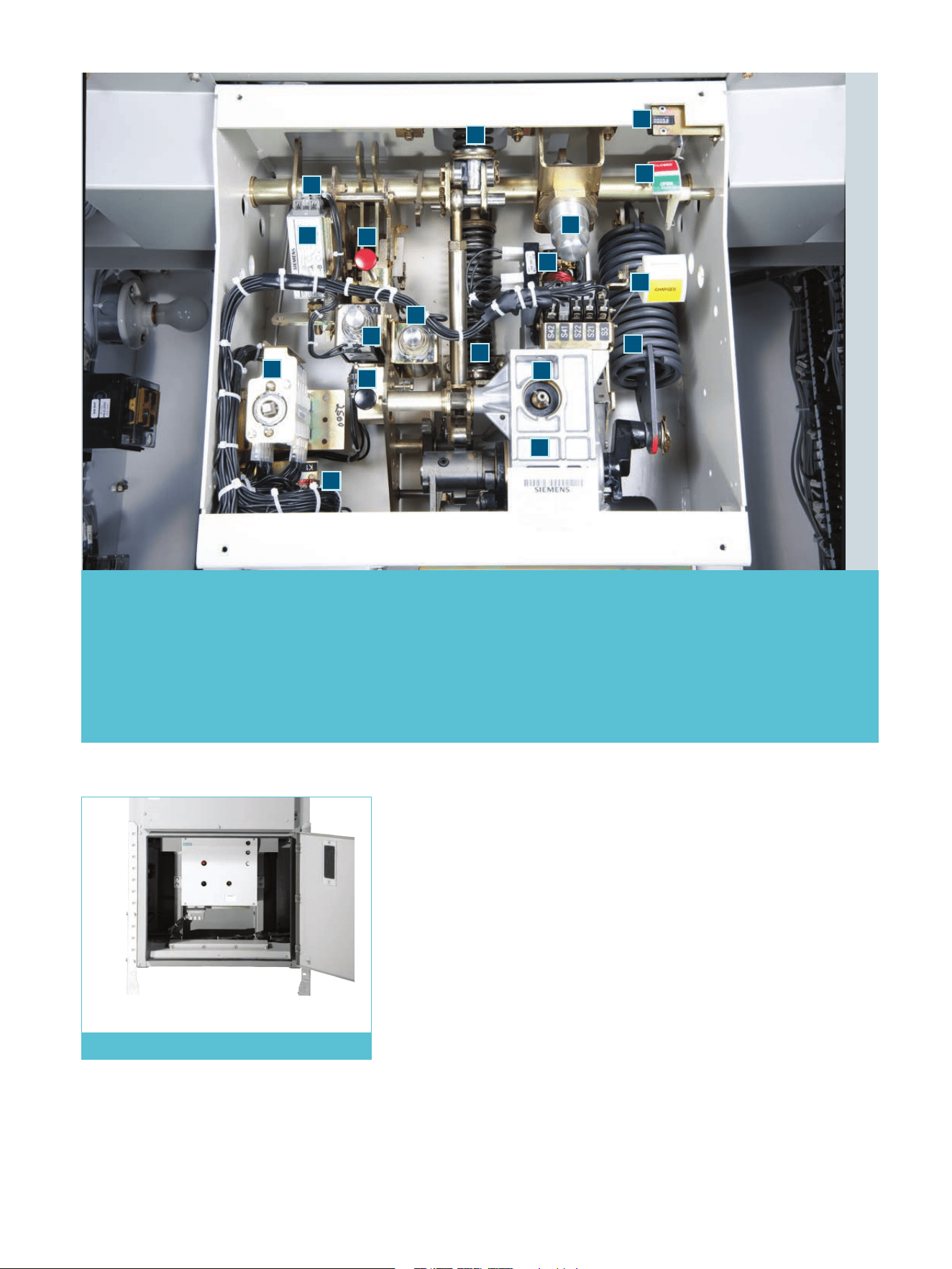
Type 3AH35-SE operator compartment
1. Spring charging gearbox
2. Closing spring
3. Opening spring
4. Main rotating shaft
5. Contact pressure spring
6. Opening operation shock
absorber
7. Spring charging motor
8. Manual spring charging
access port
9. OPEN-CLOSE indicator
10. CHARGED-DISCHARGED
indicator
11. Mechanical operation
counter
12. Spring release (close) coil
13. Manual close pushbutton
14. Trip coil
15. Manual open (trip)
pushbutton
16. Auxiliary switch
17. Anti-pump relay
18. Undervoltage trip
device (optional)
11
10
3
4
5
15
14
7
13
1
2
12
6
9
8
16
17
18
7
Brochure | SDV7

Type 3AH35-MA magnetic-actuator
operator
The type SDV7 distribution circuit breaker is
available with a magnetic-actuator operator.
The basic configuration of the circuit
breaker is the same as for the stored-energy
version, including the high-voltage
elements and the vacuum interrupters, with
only the operating mechanism replaced.
The type 3AH35-MA magnetic-actuator
operator employs rare-earth magnets
(neodymium-iron-boron) to maintain a
stable CLOSED position, in combination with
an electromagnetic coil structure to change
from the OPEN position to the CLOSED
position. The magnetic actuator uses a
single coil design, providing a stable OPEN
and a stable CLOSED position without
supplemental energy input. The electronic
controller provides a substantial current to
the electromagnetic coil for closing
operation, so that the electromagnetic force
adds to the magnetic force provided by the
rare-earth magnets.
For opening, only a modest electromagnetic
force is needed, in the reverse direction, to
offset the magnetic force provided by the
rare-earth magnets. In effect, the
electromagnetic force cancels the magnetic
force during opening operations.
The force for opening primarily is provided
by the contact pressure springs on each
phase (not shown) with an assist from the
opening spring. The opening spring is the
same as used on the stored-energy version,
and its primary function is to provide the
force to oppose the force of atmospheric
pressure on the vacuum interrupter bellows,
which would otherwise cause the contacts
of the open circuit breaker to close.
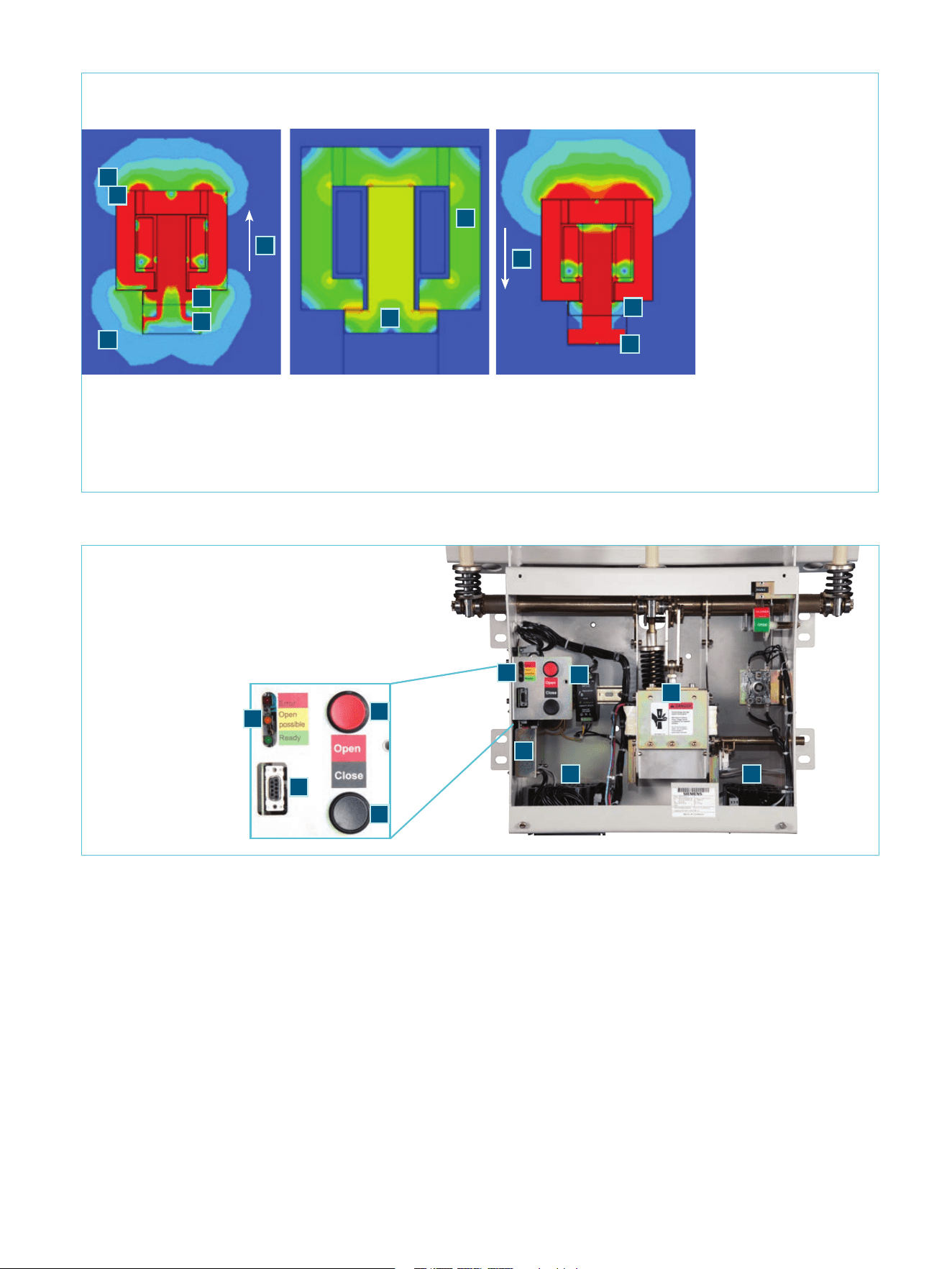
The field diagrams of the magnetic actuator
illustrate the combined magnetic and
electromagnetic field conditions in the
various circuit breaker positions.
Magnetic-actuator electronic controller
The operation of the magnetic actuator is
controlled by an electronic module. The
electronic module receives power from a
24 Vdc power supply, stores energy in
capacitors on several printed circuit boards,
and provides a variety of functions,
including:
Closing, upon remote (or relay) command
or from local pushbutton
Opening, upon remote (or relay)
command or from local pushbutton
Capacitor control, including charging,
monitoring, and periodic condition
checking.
The electronic controller allows for circuit
breaker reclosing according to the standard
reclosing duty sequence in ANSI/IEEE
C37.04, O – 0.3 s – CO – 15 s – CO. The
capacitors used to power circuit breaker
opening and closing actions recharge
following operations as follows:
After a C operation ≈ 10 s
After an O operation ≈ 2-5 s
After a CO operation ≈ 12-15 s.
When first energized, the capacitors require
approximately 35 s to obtain full charge.
The electronic controller is designed for
harsh environments and long life. The
estimated life of the electronic controller is
approximately 20 years with an ambient
environment outside the circuit breaker
enclosure of 50 °C or less.
In an environment less harsh than this, the
expected life is well in excess of 20 years.
The capacitors used have a life expectancy
of 45 years with an ambient environment at
the capacitors of 70 °C (3% of total hours),
50 °C (40% of total hours), with the
remaining 57% of total hours in an ambient
of 40 °C or less. In an environment less
harsh than this, the expected life is well in
excess of 45 years.
Type 3AH35-MA
Magnetic-actuator operator
1. Coil
2. Armature
3. Core
4. Transfer rod
5. Rare-earth magnets
6. Opening spring
7. Main rotating shaft
Basic elements of the
magnetic actuator
2
3
5
4
5
6
7
1
8
SDV7 | Brochure
The capacitor boards are generously sized,
with energy storage above the level needed
to operate the circuit breaker. In fact, the
system is able to open and close the circuit
breaker if as much as 20% of the capacitors
are disabled.
The capacitors have reserve energy such
that the circuit breaker can be electrically
opened using the pushbuttons on the
operator for at least 300 seconds after
control power is lost.
5. RS-232 PC interface
6. Local pushbuttons
(black-close, red-open)
7. Green LED (power supply
behind front cover)
1. Magnetic field from
rare-earth magnets
2. Electromagnetic field
due to current coil
3. Direction of armature
movement during
closing
4. Direction of armature
movement during
opening
5. Armature at start (in
OPEN position)
6. Armature at start (in
CLOSED position)
7. Armature at end (in
CLOSED position)
8. Armature at end (in
OPEN position)
9. Armature in CLOSED
position
Fields while circuit breaker closed -
magnetic field maintains CLOSED
position
Fields during opening -
electromagnetic field opposes
(cancels) magnetic field
Electromagnetic and magnetic fields condition in various circuit breaker positions
Close Close
Open
Fields during closing -
electromagnetic and magnetic
fields additive
Close
Open
The power supply for the electronics circuits
accommodates a wide range of input
voltages. The high-range power supply
accepts any voltage in the range of 110 Vac
to 240 Vac or 110 Vdc to 250 Vdc. The low-
range power supply accepts voltage in the
range of 28 Vdc to 56 Vdc..
Electrical close and open commands operate
through binary inputs, with the high-range
command input version requiring input of at
least 68 Vac or 68 Vdc for operation, while
the low-range command input version
requires input of at least 17 Vac or 17 Vdc
for operation.
1. Electronic controller
2. Capacitor board
3. Magnetic actuator
4. LED
5. RS-232 PC interface
6. Local pushbuttons
(black-close, red-open)
7. Green LED (power
supply behind front
cover)
2
3
5
4
8
6
7
1
2
Operator elements, controls and indicators
4
3
5
7
1
2 2
4
6
6
9
1
9
Brochure | SDV7
Automatic monitoring
The electronic controller includes
monitoring and self-test functions, among
which are these:
Failure to close on command
(after 100 ms)
Excessive coil current
Capability of capacitors
Initial charging of capacitors on
energization
Periodic charging test cycle to verify
energy storage capacity
(performed weekly)
Power supply (24 Vdc) failure
Overcharging of capacitors
(excess voltage)
Coil circuit integrity
Interlock check (lockout).
The electronic controller also maintains a
log, which includes details of the last 32
operations and results of capacitor
capability tests.
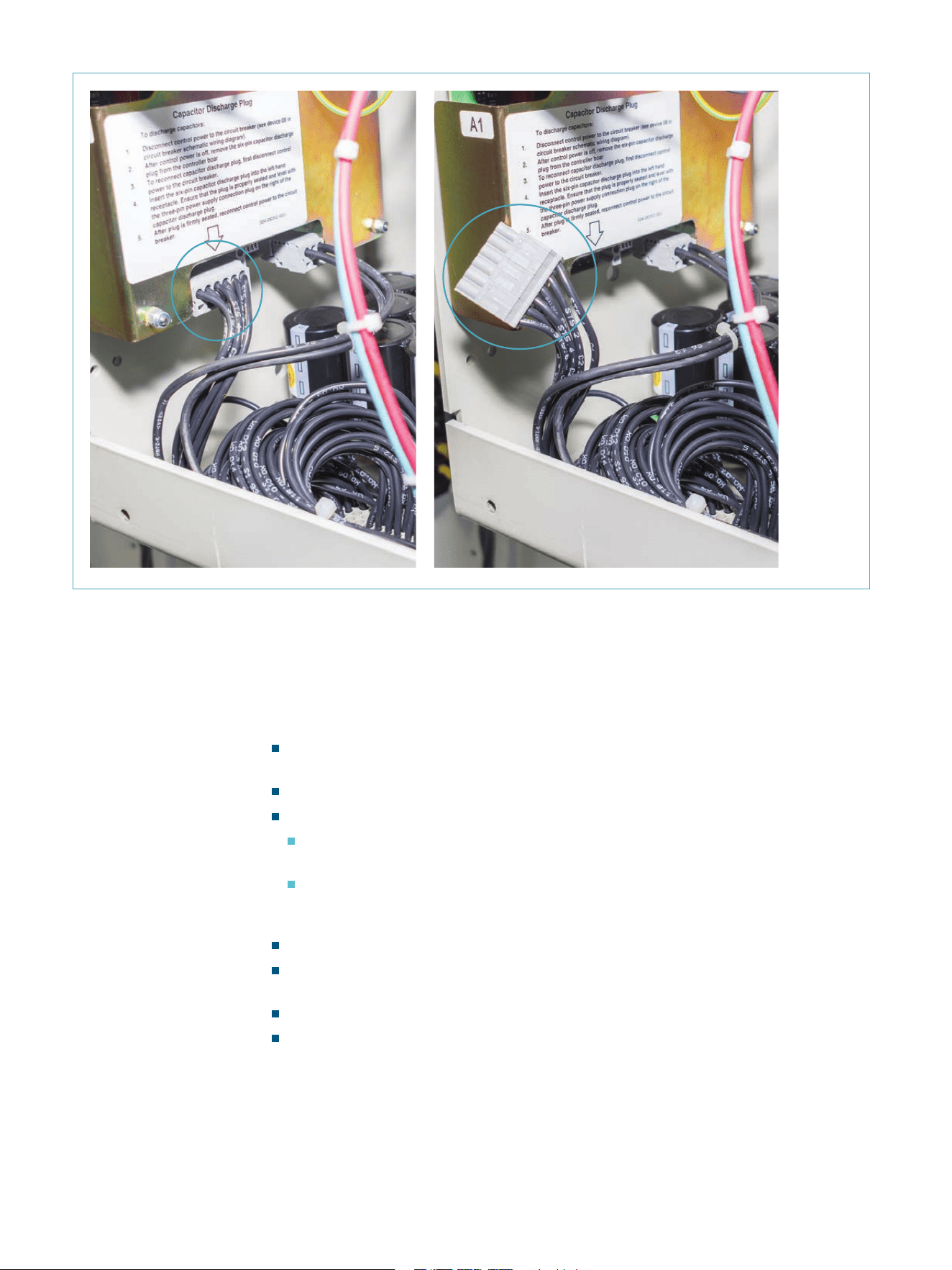
Built-in fast-discharge circuit for
capacitors
The controller system design includes built-
in means to discharge the capacitors if
maintenance is to be performed. There is no
need for the user to provide jumper wires or
loading resistors to discharge the capacitors
– simply disconnect the plug between the
electronic controller board and the capacitor
boards, and the discharge circuit is
automatically enabled, discharging the
capacitors to a low level to enable
maintenance. The NEC (NFPA 70) requires
discharge to below 50 Vdc within five
minutes, but the system incorporated in the
type SDV7-MA magnetic actuator design
discharges to less than 5 Vdc in
approximately 90 seconds.
When control power is initially energized,
the controller executes a start-up routine,
after which charging of the capacitors
begins.
When control power is first applied, a green
LED on the power supply (item 7 on page 9)
is illuminated.
The controller includes LEDs to indicate the
energy status of the capacitor bank.
Detail of
electronic
controller
and pull
to plug to
discharge
capacitors
10
SDV7 | Brochure
From complete discharge, approximately 25
seconds after control power is applied, a
yellow LED lights, and approximately 5 to 10
seconds later, the yellow LED goes off and a
green LED illuminates. The LEDs indicate
status as follows:
Green LED on power supply illuminated
(visible with operator cover removed)
indicates control power is available
Green LED (adjacent to pushbuttons)
illuminated indicates the operator is ready
and is capable of Open-Close-Open
sequence
Yellow LED (adjacent to pushbuttons)
illuminated indicates the operator is
capable of an Open operation
Red LED (adjacent to pushbuttons)
illuminated indicates error and the energy
is not sufficient for operation.
The controller includes output terminals
corresponding to the LEDs so that status can
be monitored from remote locations.
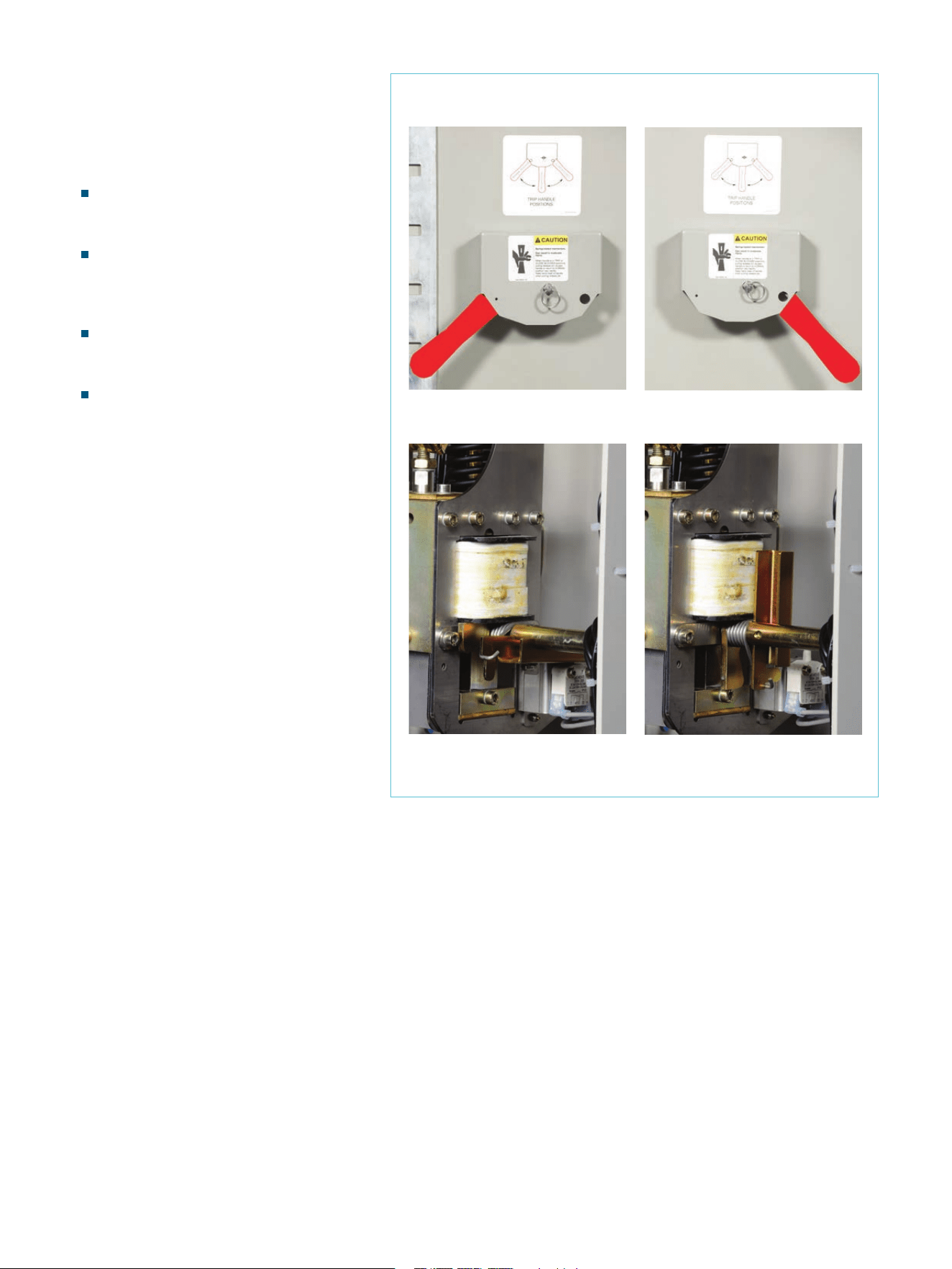
External manual trip handle
An external manual trip handle is provided
as standard on the type SDV7-MA and type
SDV7-MA-AR with magnetic-actuator
operator. The external manual trip handle
requires only a modest force to operate it,
and once the circuit breaker is opened, the
handle can be padlocked to provide a
lockout function and prevent closing of the
circuit breaker either by electrical means or
by manual means.
External manual trip handle
Handle in normal position
Handle in lockout position
Interlock not blocked
(cover removed for photo)
Interlock blocked
(cover removed for photo)
11
Brochure | SDV7
Arc-resistant enclosure option
The SDV7 family is available with an option
for arc-resistant construction.
For arc-resistant capability, the basic type
SDV7 enclosure is modified to include relief
openings, along with exhaust channels on
the sides of the enclosure to route the
exhaust gases associated with an internal
arcing event to the sides of the enclosure
and thence to exhaust flaps located on the
top of the side exhaust channels.
The modifications also include pressure-
actuated flaps to close ventilation openings
between the low-voltage compartments and
the high-voltage compartment when an
arcing event occurs.
The design has been successfully tested for
resistance to internal arcing in accordance
with ANSI/IEEE C37.20.7 for accessibility
type 2B. Accessibility type 2B means that a
degree of protection is provided on all four
sides of the enclosure, and this protection is
provided even if a low-voltage compartment
door is open. The rated arcing current is
equal to the rated short-circuit current of
the circuit breaker as shown on page 13,
and the rated arcing current duration is
0.5 s, in accordance with ANSI/IEEE
C37.20.7.
The basic enclosure dimensions and
footprint are unchanged from the non-arc-
resistant version, simplifying application.
The exhaust channels add to the overall
space occupied by the enclosure, as shown
in the dimensional figures on page 14.
Arc-resistant
enclosure option
1. Relief opening
2. Exhaust channel
3. Exhaust flap on top of exhaust channel
Type SDV7-AR
2
3
3
1
2
12
SDV7 | Brochure
Technical ratings and
dimensions
Technical ratings
Circuit
breaker
type SDV7
Rated
maximum
voltage
Rated withstand
voltages
Rated
short-
circuit and
short-time
current
Rated
interrupting
time
2
Rated continuous
current
Rated transient
recovery voltage
3
Rated
permissible
tripping
delay time Y
Rated
closing
and
latching
current
Lightning
impulse
(BIL)
1
Power
frequency
u
c
TRV
peak
value
t
3
time to
voltage
u
c
kV, rms kV
3
kV kA, rms ms/cycles A, rms kV μs sec kA, peak
15.5-20 15.5 110/142 50 20 50/3 1,200, 2,000 29.2 32 2 52
15.5-25 15.5 110/142 50 25 50/3 1,200, 2,000 29.2 32 2 65
15.5-31.5
4
15.5 110/142 50 31.5 50/3 1,200, 2,000, 3,000 29.2 32 2 82
15.5-40
4
15.5 110/142 50 40 50/3 1,200, 2,000, 3,000 29.2 32 2 104
27.6-20 27.6 150/194 60 20 50/3 1,200, 2,000 52.1 45 2 52
27.6-25 27.6 150/194 60 25 50/3 1,200, 2,000 52.1 45 2 65
38.0-20
4
38.0 200/258 80 20 50/3 1,200, 2,000 71.7 59 2 52
38.0-25
4
38.0 200/258 80 25 50/3 1,200, 2,000 71.7 59 2 65
38.0-31.5
4
38.0 200/258 80 31.5 50/3 1,200, 2,000, 2,500 71.7 59 2 82
38.0-40
4
38.0 200/258 80 40 50/3 1,200, 2,000, 2,500 71.7 59 2 104
Footnotes:
1
First value is full-wave impulse withstand circuit
breaker open or closed. Second value is chopped-
wave impulse withstand, applicable only with circuit
breaker closed.
2
50 ms interrupting time standard. 83 ms
interrupting time optional with stored-energy
operator only.
3
TRV values are in accordance with ANSI/IEEE C37.06-
2009 TRV peak value u
c
roughly equal to historic E
2
value in ANSI/IEEE C37.06-2000. Value t
3
, time to
voltage u
c
is approximately 1/1.138 times T
2
value in
ANSI/IEEE C37.06-2000.
4
Availability of this rating with magnetic-actuator
operator to be announced. Consult factory.
13
Brochure | SDV7
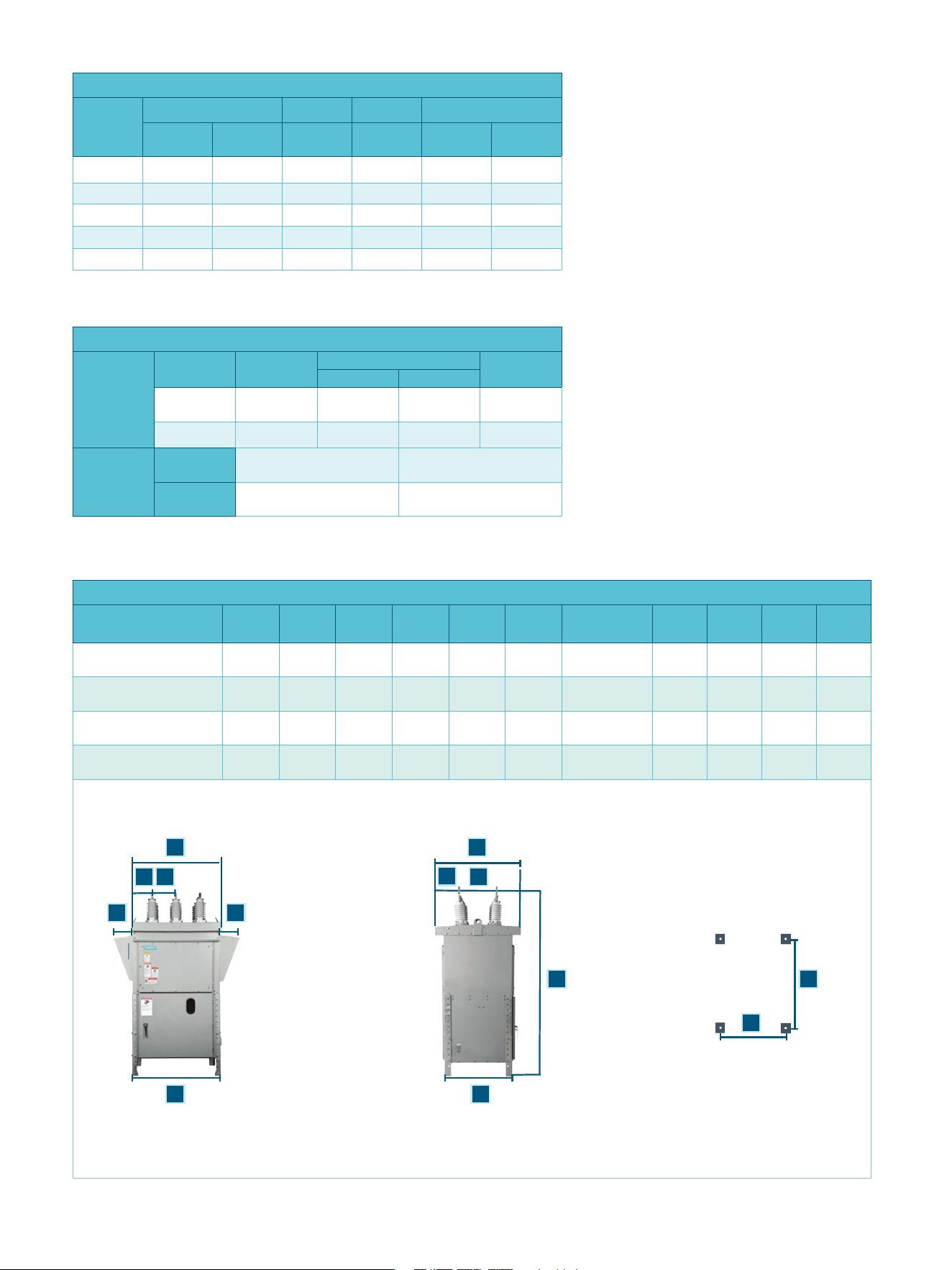
BA
C
K
G
I
E
F
J
H
D
Rear Front
Front
Rear
Side viewFront view
K
Dimensions in inches (mm)
Rating A B C D E F G H I J K
5
15.5 kV,
1,200 A-2,000 A
10.7
(272)
13.0
(330)
47.1
(1,197)
44.5
(1.130)
12.4
(315)
19.8
(503)
92.0-116.0
(2,337)-(2,945)
36.1
(918)
31.3
(794)
42.7
(1,084)
10.3
(260)
15.5 kV,
3,000 A
12.3
(312)
16.0
(406)
56.5
(1,435)
52.8
(1,340)
15.9
(403)
21.0
(534)
96.0-120.0
(2,438)-(3,048)
44.2
(1,123)
39.4
(1,001)
52.0
(1,321)
11.4
(290)
27.6 kV,
1,200 A-2,000 A
12.3
(312)
16.0
(406)
56.5
(1,435)
49.8
(1,265)
14.4
(366)
21.2
(538)
96.0-120.0
(2,438)-(3,048)
44.2
(1,123)
39.4
(1,001)
52.0
(1,321)
11.4
(290)
38.0 kV,
1,200 A, 2,000 A, 2, 500 A
13.4
(340)
19.5
(495)
67.8
(1,723)
63.0
(1,600)
20.4
(518)
22.2
(563)
120.5-144.5
(3,060)-(3,670)
55.6
(1,413)
50.9
(1,294)
63.1
(1,604)
16.7
(424)
C
Footnotes:
1
First value is for standard 50 ms/three-cycle
interrupting time. Second value is for optional
83 ms/five-cycle interrupting time (stored-energy
operator only).
2
If controller power fails, capacitors retain
sufficient charge to open circuit breaker within
300 seconds, with minimum open command
duration 100 ms.
3
Capacitors discharge to 10 V or less within five
minutes after disconnecting plug.
4
Capacitor charging time approximately 30-35
seconds from complete discharge, approximately
12 seconds after OPEN-CLOSE-OPEN sequence.
5
On initial energization, power demand is
approximately 100 W, declining to approximately
20 W when capacitors are fully charged. When the
circuit breaker operates (open or close), power
demand again increases to approximately 100 W,
declining to approximately 20 W when capacitors
are fully charged.
Control data for stored-energy operator
Nominal
Range Close coil Trip coil
1
Spring charging motor
Close Trip A A
Amperes
run (avg.)
Charging
seconds
48 Vdc 36-56 28-56 11.4 30/11.4 8 10
125 Vdc 90-140 70-140 2.1 7.4/4.8 4 10
250 Vdc 180-280 140-280 2.1 9.6/4.2 2 10
120 Vac 104-127 104-127 2.0 --- 6 10
240 Vac 208-254 208-254 2.0 --- 3 10
Control data for magnetic-actuator operator
Electronic
controller
Input voltage
range
Input power
Controller output
Capacitor
voltage
2,3,4
Close Open
95-250 Vdc/
100-254 Vac
60 W/60 V
5
40-55 A 10-15 A 160 Vdc
28-56 Vdc 80 W
5
40-55 A 10-15 A 160 Vdc
Binary inputs
(close and
open
commands)
Low-range
model
≥ 17 Vdc or 17 Vac Duration ≥ 100 ms
High-range
model
≥ 69 Vdc or 53 Vac Duration ≥ 100 ms
14
SDV7 | Brochure
Standard features for all types include:
Visual circuit breaker status window
Operations counter
Mechanical position indicator
External manual trip means
Generous relay and metering space
Hinged panel for relays or devices
Necessary terminal blocks and wiring
Fused knife-switch control voltage
disconnects
Porcelain dry-type roof bushings
Bolted cabinet construction
Permanent lifting eyes (2)
Adjustable galvanized legs (4)
Corrosion resistant powder paint finish
(ANSI-61 light gray with white for interior
panels of the low-voltage relay and
control compartment)
Stainless steel external ground pads (2)
Stainless steel external hardware
Cabinet heaters to prevent condensation
Filtered ventilation
ANSI/IEEE rain-tested design
(per ANSI/IEEE C37.20.2)
Reduced footprint from previous models.
Options available for all types include:
Terminal connectors for bushings
Terminal connectors for ground
Current transformers (up to two per
bushing)
Siemens protective relays
Other protective relays
Local/remote or toggle switches
Additional heaters for -40
°
C application
(consult factory for -50
°
C application)
Heaters applied at ½ voltage
Adjustable thermostat
Seismic capability (IEEE 693 high level,
UBC zones 1-4 or IBC-2006)
Interior convenience outlet (GFCI)
Interior light with switch
Molded-case circuit breakers in lieu of
fused knife switches
Wire markers
Arc-resistant construction accessibility
type 2B (to ANSI/IEEE C37.20.7, 0.5 s
duration).
Stored-energy operating mechanism type
3AH35-SE:
Close and trip coil
Options available:
Capacitor trip unit for alternating
current (ac) tripping supply
Second trip coil
Undervoltage trip device
Additional auxiliary switch contacts
Circuit breaker control switch with
indicating lights.
Magnetic-actuator operating mechanism
type 3AH35-MA
Pushbuttons for local close and open
Options available:
Additional auxiliary switch contacts
Binary input voltage:
High range ≥ 68 Vdc or 68 Vac
Low range ≥ 17 Vdc or 17 Vac.
Electronic power supply:
28-56 Vdc
95-250 Vdc / 100-254 Vac.
Maintenance interval
If applied under ANSI usual service
conditions, maintenance is only needed at
intervals of five years/10,000 operations on
any circuit breaker in an outdoor
application.
Standards
The type SDV7 meets
the following
standards:
ANSI/IEEE C37.04
rating structure for
ac high-voltage
circuit breakers
ANSI/IEEE C37.09
test procedure for
ac high-voltage
circuit breakers
ANSI/IEEE C37.06
preferred ratings ac
high-voltage circuit
breakers
NEMA SG-4
ac high-voltage
circuit breakers.
Arc-resistance
ANSI/IEEE C37.20.7
Testing for internal
arcing faults (for
arc-resistant units)
Seismic
When specified, the
distribution vacuum
circuit breaker can be
provided with the
capability of
maintaining structural
integrity during and
following a seismic
disturbance, as
appropriate for the
specified UBC zones
1-4, IBC-2006 or IEEE
693 levels.
Features and benefits
15
Brochure | SDV7
Published by Siemens Industry, Inc. 2016.
Siemens Industry
7000 Siemens Road
Wendell, North Carolina 27591
For more information, please contact our Customer Support Center.
Phone: +1 (800) 347-6659
www.usa.siemens.com/sdv7
Article No. EMMS-T40004-01-4A00
Printed in U.S.A.
© 2016 Siemens Industry, Inc.
Subject to changes and errors. The information given in this document
only contains general descriptions and/or performance features which
may not always specifically reflect those described, or which may
undergo modification in the course of further development of the
products. The requested performance features are binding only when
they are expressly agreed upon in the concluded contract.
01010011 01000100 01010110 00110111 00100000
01010011 01000100 01010110 00110111 00100000