Loading ...
Loading ...
Loading ...
Waveform Setup
R&S
®
RTB2000
36User Manual 1333.1611.02 ─ 03
4 Waveform Setup
This chapter describes how to connect and set up probes, to adjust the horizontal and
vertical settings, and to control the acquisition.
4.1 Connecting Probes and Displaying a Signal
Risk of instrument damage
Make sure to set the attenuation factor on the instrument according to the probe being
used. Otherwise, the measurement results do not reflect the actual voltage level, and
you might misjudge the actual risk.
The attenuation of the probes that are delivered with the instrument, and the default
attenuation factor of the instrument are 10:1. If you use only the delivered probes and
did not change the attenuation factor, no attenuation adjustment is required.
1. Connect the probes first to the channel inputs, and then to the DUT.
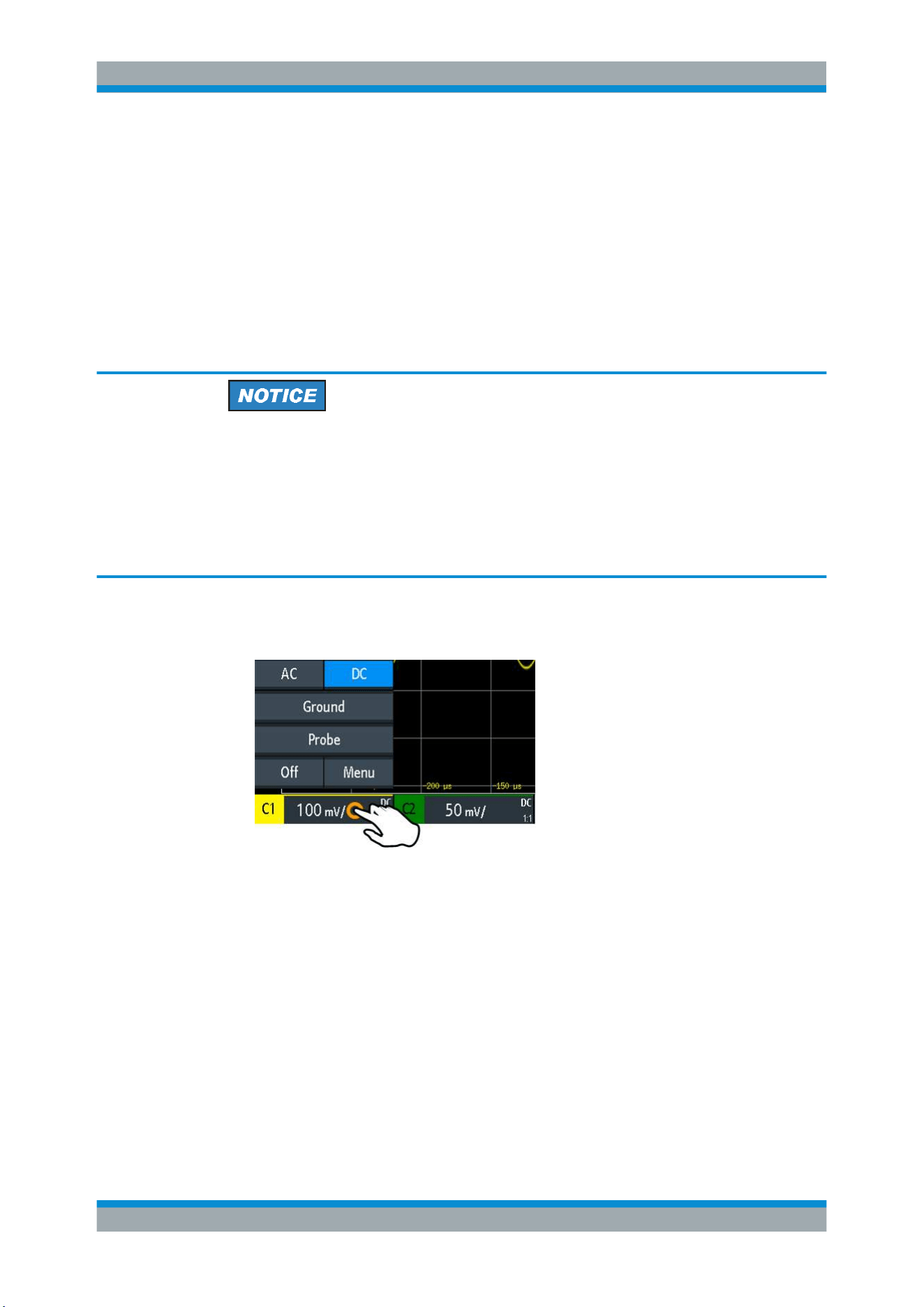
2. Tap the label of the used channel in the bottom line of the display.
3. Tap "Probe".
4. Select the attenuation factor of the probe.
The probe's attenuation factor is indicated on the probe.
Note: If you measure current using a shunt resistor as a current sensor, you have
to multiply the V/A-value of the resistor by the attenuation of the probe. For exam-
ple, if a 1 Ω resistor and a 10:1 probe is used, the V/A-value of the resistor is 1 V/A.
The attenuation factor of the probe is 0.1, and the resulting current probe attenua-
tion is 100 mV/A.
5. If you connect several probes, repeat steps 2 to 4 for the remaining channels.
6. Press the PRESET key.
7. Press the AUTOSET key.
Connecting Probes and Displaying a Signal
Loading ...
Loading ...
Loading ...