Loading ...
Loading ...
Loading ...
Serial Bus Analysis
R&S
®
RTB2000
189User Manual 1333.1611.02 ─ 03
12.4.1 The UART / RS232 Interface
The Universal Asynchronous Receiver/Transmitter UART converts a word of data into
serial data, and vice versa. It is the base of many serial protocols like of RS-232. The
UART uses only one line, or two lines for transmitter and receiver.
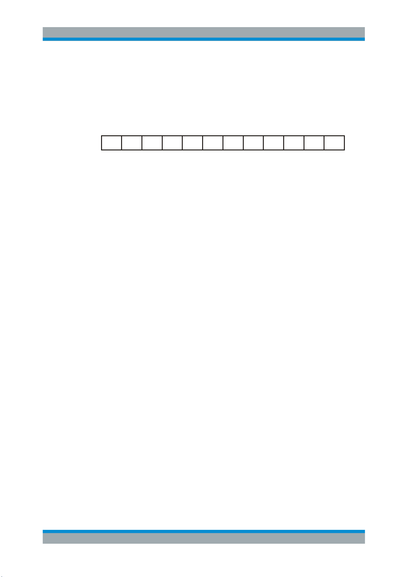
Data transfer
[Data8]
[Parity]
Stop[Data7][Data6][Data5]
Data4Data3Data2Data1Data0
Start
Figure 12-15: Bit order in a UART word (symbol)
●
The start bit is a logic 0.
●
The stop bits and the idle state are always logic 1.
The UART protocol has no clock for synchronization. The receiver synchronizes by
means of the start and stop bits, and the bit rate that must be known to the receiver.
Trigger
The R&S RTB2000 can trigger on specified parts of UART serial signals:
●
Start bit
●
Parity errors, and breaks
●
A serial pattern at any or a specified position
12.4.2 UART Configuration
The correct setup of the protocol parameters and the threshold is the condition for
decoding the signal.
To set up and decode a UART signal
1. Press the PROTOCOL key in the Analysis area of the front panel.
2. Select the bus that you want to use: B1 or B2.
3. Select the "Bus Type" = UART.
4. Select "Configuration".
5. Select the "Source", the channel to which the input signal is connected.
6. Set the threshold. Use one of the following methods:
● Tap "Find Threshold". The instrument evaluates the signal and sets the thresh-
old.
● Enter the threshold value in the numeric field.
7. Set the other signal parameters according to the signal characteristics. All settings
are described below.
8. In the "Bus" menu, enable "Decode".
UART / RS232 (Option R&S RTB-K2)
Loading ...
Loading ...
Loading ...