Loading ...
Loading ...
Loading ...
Serial Bus Analysis
R&S
®
RTB2000
198User Manual 1333.1611.02 ─ 03
● "Identifier and Data": combination of identifier and data condition
5. If "Identifier" or "Identifier and Data" is selected, the CAN trigger setup dialog
expands to define the serial pattern.
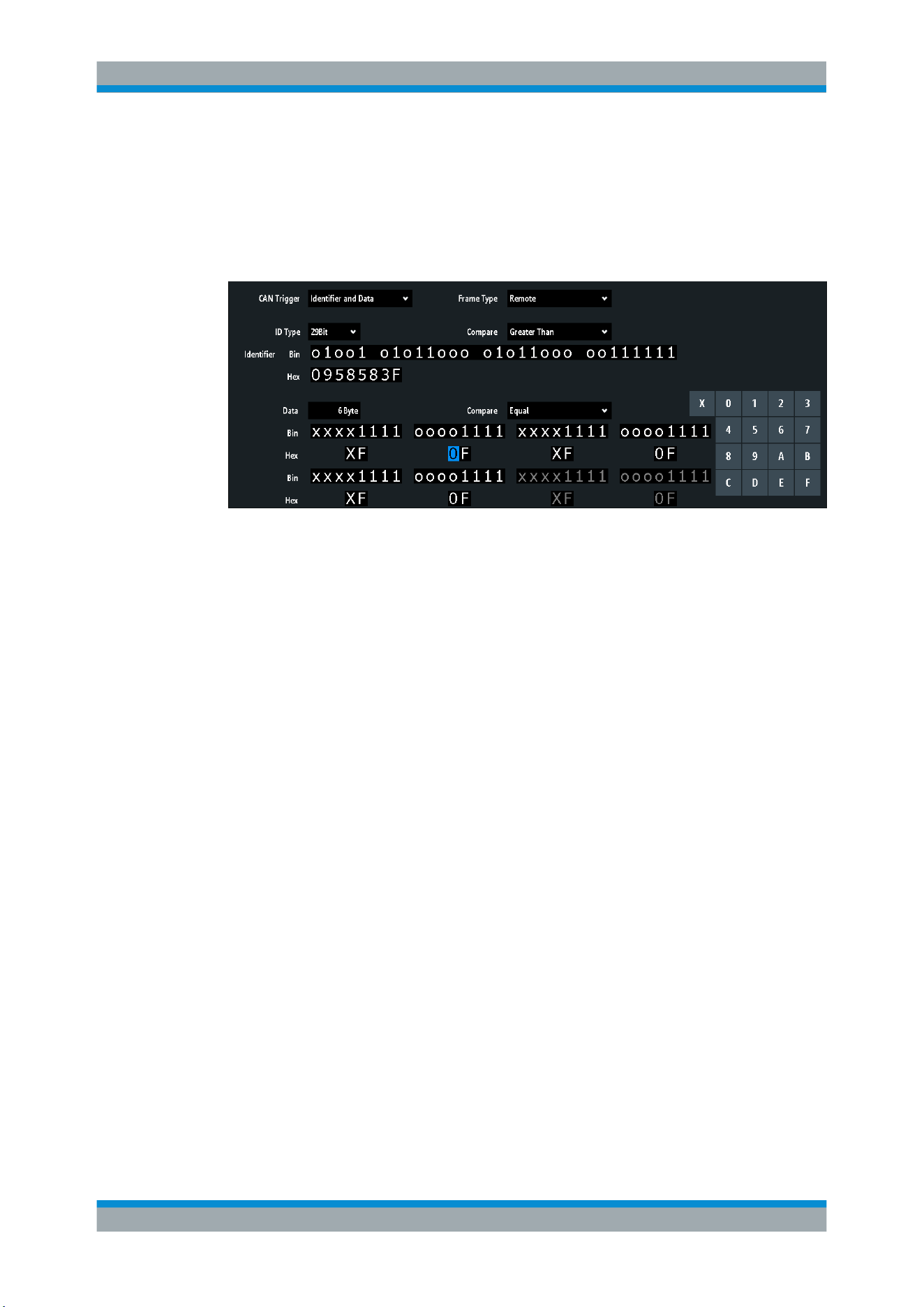
CAN trigger settings
Figure 12-19: Trigger setup dialog with an example of CAN identifier and data patterns
"CAN Trigger" = trigger on "Identifier and Data"
"Identifier" = trigger on 29-bit identifiers greater than the specified identifier
"Data" = trigger on the specified 6-byte data pattern
0 (blue) =
Selected nibble in the 2
nd
byte of the data pattern, where the blue color indicates that the
keypad is active for this nibble
CAN Trigger
Selects the trigger mode.
"Start of
Frame"
Triggers on the first edge of the dominant SOF bit (synchronization
bit).
"End of Frame"
Triggers on the end of the frame (7 recessive bits).
"Frame"
Triggers on the frame type that is selected with "Frame"
See:
"Frame" on page 199.
"Error"
Triggers on a frame error. An error frame is sent by a node that has
detected an error.
See:
"Error" on page 199.
"Identifier"
Triggers on a specific message identifier or an identifier range.
If a label list with node names was loaded and applied in the bus con-
figuration, you can select simply the "Symbolic ID" instead of entering
the numeric identifier.
See:
"Identifier condition" on page 200.
"Identifier and
Data"
Triggers on a combination of identifier and data condition. The instru-
ment triggers at the end of the last byte of the specified data pattern.
See:
"Identifier condition" on page 200 and "Data condition"
on page 200.
Remote command:
TRIGger:A:CAN:TYPE on page 404
CAN (Option R&S RTB-K3)
Loading ...
Loading ...
Loading ...