Loading ...
Loading ...
Loading ...
Signal Generation (Option R&S RTB-B6)
R&S
®
RTB2000
239User Manual 1333.1611.02 ─ 03
14.2.5 Settings for Manual Pattern
P0/P1/P2/P3
Sets the states to high or low for the respective pin of the manual pattern.
Remote command:
PGENerator:MANual:STATe<s> on page 454
14.2.6 Settings for Serial Buses
You can use the pattern generator to generate BUS signals.
The signals of the BUS signal source are pseudo random pattern and are not adapta-
ble. Only the BUS type and the data rate can be selected.
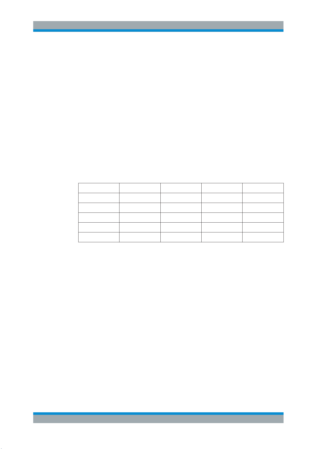
The contact at the upper left is always ground and the signal levels are about 1 V. The
following table shows how the four outputs P0, P1, P2 and P3 are used, depending on
the signal.
Signal P0 P1 P2 P3
UART Tx Rx Unused Unused
SPI Clock Mosi Miso Chip Select
I2C Clock SCL Data SDA Unused Unused
CAN CAN H CAN L Unused Unused
LIN High Low Unused Unused
Data Rate
Select the data rate of the bus signal.
The following values are available for the specific bus:
●
UART: 9600 Bit/s, 115.2 kBit/s, 1 MBit/s
●
SPI: 100 kBit/s, 250 kBit/s, 1 MBit/s
●
I2C: 100 kBit/s, 400 kBit/s, 1000 kBit/s, 3400 kBit/s,
●
CAN: 50 kBit, 100 kBit, 1 MBit,
●
LIN: 9.6 kBit, 10.417 kBit, 19.200 kBit
Active
Sets the polarity for the UART bus.
Pattern Generator
Loading ...
Loading ...
Loading ...