Loading ...
Loading ...
Loading ...
Serial Bus Analysis
R&S
®
RTB2000
182User Manual 1333.1611.02 ─ 03
12.3.2
I
2
C Configuration
The correct setup of the protocol parameters and the threshold is the condition for
decoding the signal.
To set up and decode an I
2
C signal
1. Press the PROTOCOL key in the Analysis area of the front panel.
2. Select the bus that you want to use: B1 or B2.
3. Select the "Bus Type" = I2C.
4. Select "Configuration".
5. Select the "SCL", the channel to which the clock line is connected.
6. Select the "SDA", the channel to which the data line is connected.
7. Set the threshold. Use one of these methods:
● Tap "Find Threshold". The instrument evaluates the signal and sets the thresh-
old.
● Enter the threshold value in the numeric field.
8. In the "Bus" menu, enable "Decode".
I
2
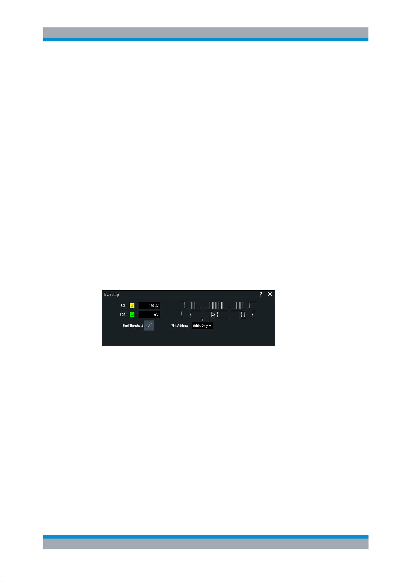
C configuration settings
Figure 12-10: I2C setup dialog
SCL............................................................................................................................. 182
SDA.............................................................................................................................182
Threshold, Find Threshold.......................................................................................... 183
SCL
Selects the source channel to which the clock line is connected.
If the MSO option R&S RTB-B1 is installed, you can use logic channels as source.
Remote command:
BUS<b>:I2C:CLOCk:SOURce on page 384
SDA
Selects the source channel to which the data line is connected.
If the MSO option R&S RTB-B1 is installed, you can use logic channels as source.
I²C (Option R&S RTB-K1)
Loading ...
Loading ...
Loading ...