Loading ...
Loading ...
Loading ...
Serial Bus Analysis
R&S
®
RTB2000
177User Manual 1333.1611.02 ─ 03
● "Serial Pattern": a bit pattern in the message
5. If "Serial Pattern" is selected, the SPI trigger setup dialog expands to define the
serial pattern.
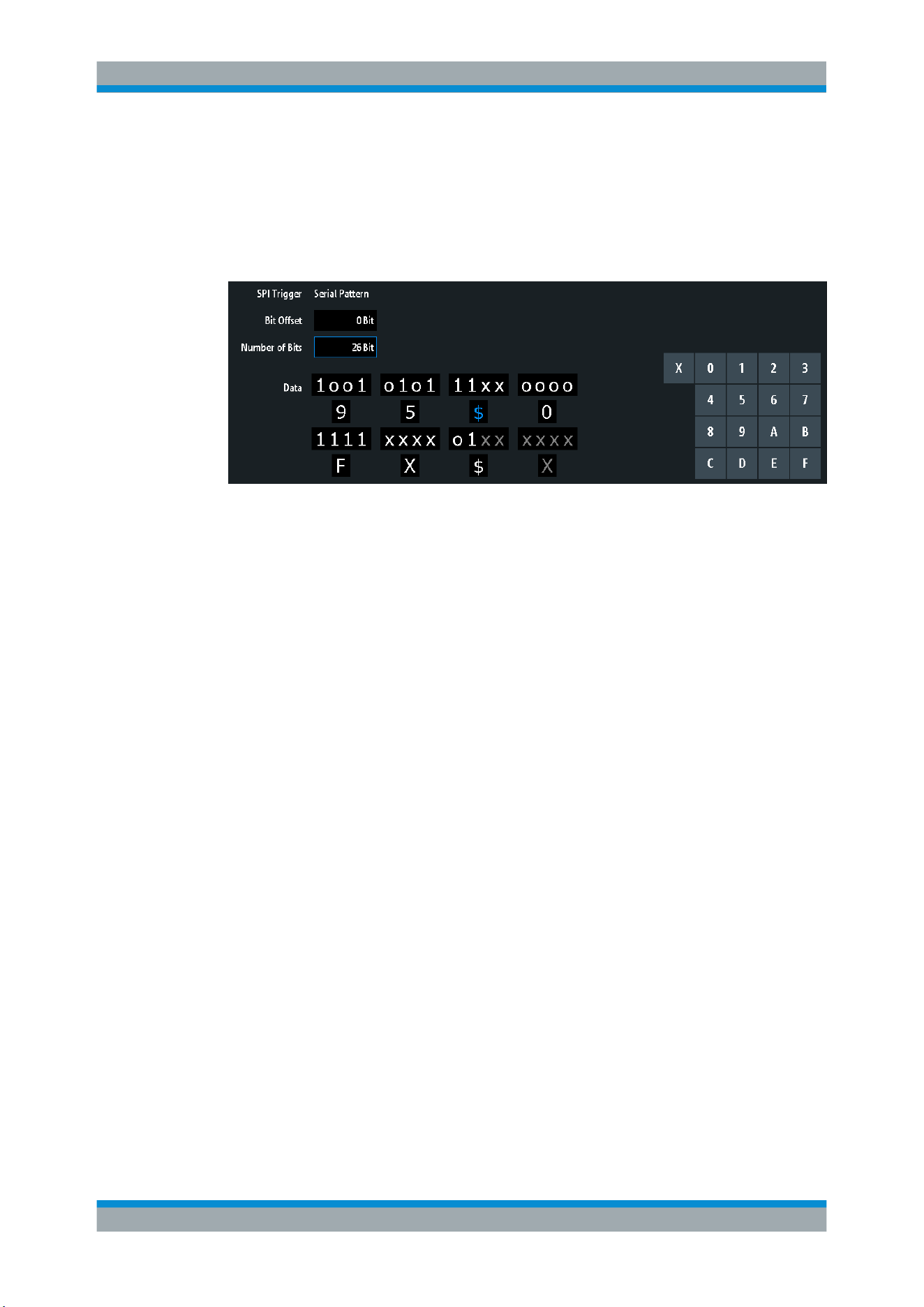
SPI/SSPI trigger settings
Figure 12-5: UART trigger settings with an example of an SPI or SSPI serial pattern
9 =
Hex value of the 1
st
nibble, with the binary value 1001
$ (blue) =
Hex value of the 3
rd
nibble, which includes some "X" bits. The blue color indicates that the key-
pad is active for this nibble.
X (white) =
The 6
th
nibble is a "don't care" nibble, as it consists of "X" bits, only
$ (white) =
The 7
th
nibble is only half contained in the specified pattern length of 26 bits
X (gray) =
The 8
th
nibble is not contained in the specified pattern
SPI Trigger..................................................................................................................177
Bit Offset..................................................................................................................... 178
Number of Bits............................................................................................................ 178
Data.............................................................................................................................178
SPI Trigger
Selects the trigger condition.
"Frame Start"
Sets the trigger to the start of the message:
●
For SPI, the frame starts when the chip select signal CS changes
to the active state.
●
For SSPI, the frame starts when the idle time has expired.
"Frame End"
Sets the trigger to the end of the message.
●
For SPI, the frame ends when the chip select signal CS changes
to the inactive state.
●
For SSPI, the frame ends when the idle time has expired after the
last clock and no new clock appeared during that time.
"Bit <x>"
Sets the trigger to the bit number specified with
"Bit Offset"
on page 178.
"Serial Pattern"
Expands the trigger setup dialog to configure the bit pattern to be trig-
gered at. Set
"Number of Bits" on page 178 and "Data" on page 178
to define the pattern, and
"Bit Offset" on page 178 to define the pat-
tern position.
SPI/SSPI Bus (Option R&S RTB-K1)
Loading ...
Loading ...
Loading ...