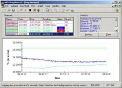
Loading ...
Loading ...
Loading ...
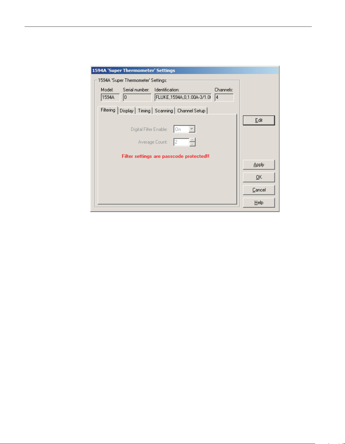
formation and the total number of channels. It also allows many thermometer
readout settings to be viewed and modified.
The 1594A/1595A Hart Super-Thermometer readout must be connected to an
available COM port and the communication settings must be properly config-
ured so that this information can be read in from the thermometer readout. If
communication with the thermometer readout is not successful, an error mes
-
sage is displayed and this dialog is blank. A progress dialog is displayed while
the current thermometer readout settings are being read in.
The Model box indicates the model number of the thermometer readout. The
Serial number box indicates the serial number assigned to this thermometer
readout. The Identification box indicates the model number, serial number and
firmware version installed in this thermometer readout. The Channels box indi
-
cates the total number of input channels on this thermometer readout.
The filtering settings can be viewed and modified by selecting the Filtering tab.
The display settings can be viewed and modified by selecting the Display tab.
The timing settings can be viewed and modified by selecting the Timing tab.
The scan settings can be viewed and modified by selecting the Scanning tab.
The Channel Setup tab displays a list of channels and allows access to probe
settings and channel settings dialogs. The settings on each of these tabs are de
-
scribed in detail in the following sections. For more detail on these settings,
please refer to the thermometer readout's User's Guide.
User’s Guide
160
Figure 128 1594A/1595A Hart Super-Thermometer settings
1.888.610.7664 sales@GlobalTestSupply.com
Fluke-Direct.com
Loading ...
Loading ...
Loading ...