Loading ...
Loading ...
Loading ...
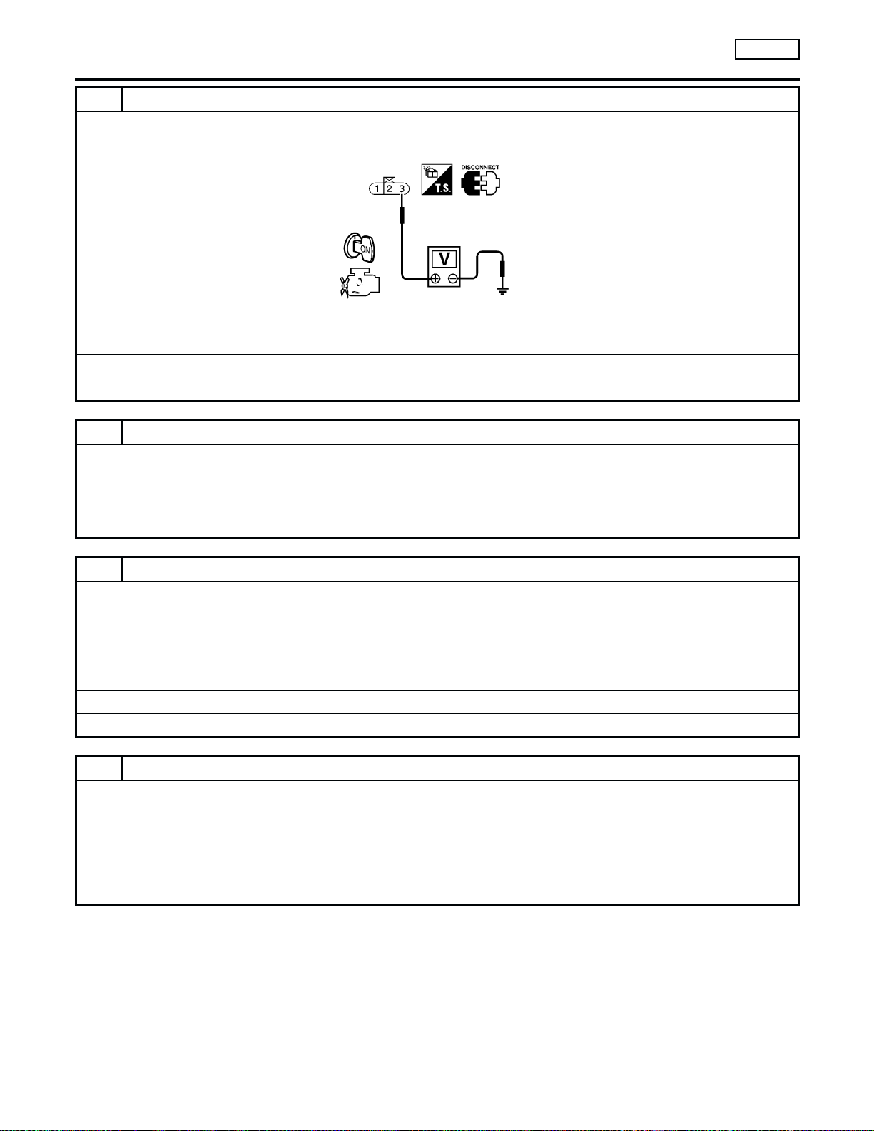
4 CHECK EVAP CONTROL SYSTEM PRESSURE SENSOR POWER SUPPLY CIRCUIT
1. Turn ignition switch ON.
2. Check voltage between terminal 3 and ground with CONSULT-II or tester.
SEF889U
Voltage: Approximately 5V
OK or NG
OK 䊳 GO TO 6.
NG 䊳 GO TO 5.
5 DETECT MALFUNCTIONING PART
Check the following.
쐌 Harness connectors C3, B113 and B101, M67
쐌 Harness connectors M58, F28
쐌 Harness for open or short between EVAP control system pressure sensor and ECM
䊳 Repair harness or connectors.
6 CHECK EVAP CONTROL SYSTEM PRESSURE SENSOR GROUND CIRCUIT FOR OPEN AND SHORT
1. Turn ignition switch OFF.
2. Check harness continuity between sensor terminal 1 and engine ground.
Refer to Wiring Diagram.
Continuity should exist.
3. Also check harness for short to power.
OK or NG
OK 䊳 GO TO 8.
NG 䊳 GO TO 7.
7 DETECT MALFUNCTIONING PART
Check the following.
쐌 Harness connectors C3, B113 and B101, M67
쐌 Harness connectors F28, M58
쐌 Joint connector-4
쐌 Harness for open or short between EVAP control system pressure sensor and ECM
쐌 Harness for open or short between EVAP control system pressure sensor and TCM (Transmission Control Module)
䊳 Repair open circuit or short to power in harness or connectors.
DTC P0450 EVAPORATIVE EMISSION (EVAP) CONTROL SYSTEM
PRESSURE SENSOR
VG33E
Diagnostic Procedure (Cont’d)
EC-990
Loading ...
Loading ...
Loading ...