Loading ...
Loading ...
Loading ...
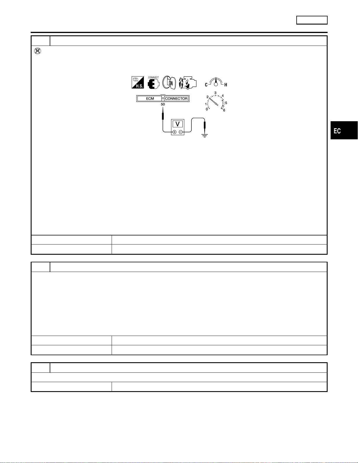
5 CHECK HEATED OXYGEN SENSOR 1 (FRONT)
Without CONSULT-II
1. Start engine and warm it up to normal operating temperature.
2. Set voltmeter probes between ECM terminal 50 [Heated oxygen sensor 1 (front) signal] and engine ground.
AEC873A
3. Check the following with engine speed held at 2,000 rpm constant under no load.
쐌 The voltage fluctuates between 0 to 0.3V and 0.6 to 1.0V more than five times within 10 seconds.
1 time: 0 - 0.3V → 0.6 - 1.0V → 0 - 0.3V
2 times: 0 - 0.3V → 0.6 - 1.0V → 0 - 0.3V → 0.6 - 1.0V → 0 - 0.3V
쐌 The maximum voltage is over 0.6V at least one time.
쐌 The minimum voltage is below 0.3V at least one time.
쐌 The voltage never exceeds 1.0V.
CAUTION:
쐌 Discard any heated oxygen sensor which has been dropped from a height of more than 0.5 m (19.7 in) onto a
hard surface such as a concrete floor; use a new one.
쐌 Before installing new oxygen sensor, clean exhaust system threads using Oxygen Sensor Thread Cleaner
tool J-43897-18 or J-43897-12 and approved anti-seize lubricant.
OK or NG
OK 䊳 GO TO 6.
NG 䊳 Replace heated oxygen sensor 1 (front).
6 CHECK SHIELD CIRCUIT
1. Turn ignition switch OFF.
2. Remove joint connector-1.
3. Check the following.
쐌 Continuity between joint connector-1 terminal 1 and ground
쐌 Joint connector-1
(Refer to “HARNESS LAYOUT”, EL-254.)
Continuity should exist.
4. Also check harness for short to ground and short to power. Then reconnect joint connector.
OK or NG
OK 䊳 GO TO 7.
NG 䊳 Repair open circuit, short to power in harness or connectors.
7 CHECK INTERMITTENT INCIDENT
Perform “TROUBLE DIAGNOSIS FOR INTERMITTENT INCIDENT”, EC-142.
䊳 INSPECTION END
DTC P0134 HEATED OXYGEN SENSOR 1 (FRONT)
(HIGH VOLTAGE)
KA24DE
Diagnostic Procedure (Cont’d)
EC-231
FE
CL
MT
AT
TF
PD
AX
SU
BR
ST
RS
BT
HA
SC
EL
IDX
GI
MA
EM
LC
Loading ...
Loading ...
Loading ...