Loading ...
Loading ...
Loading ...
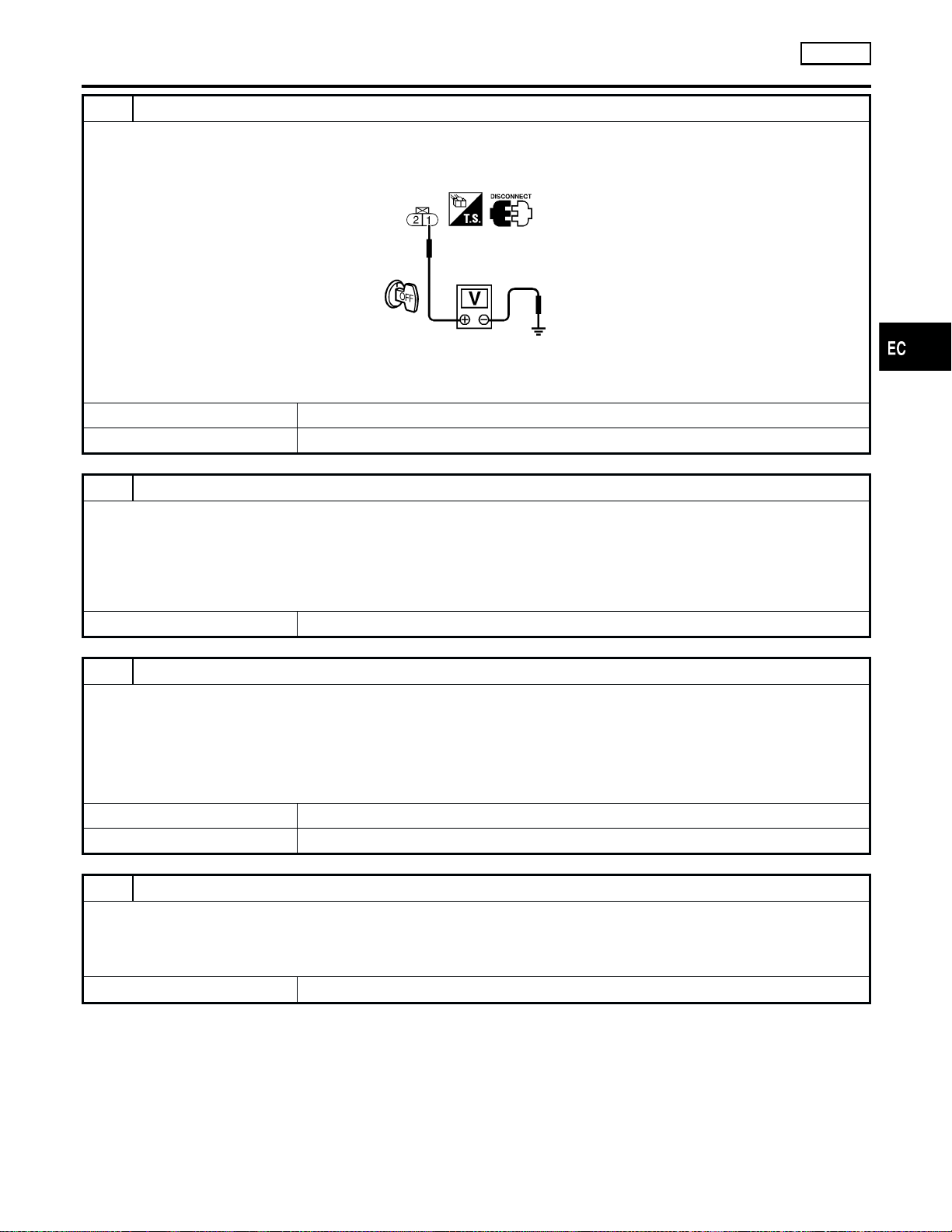
3 CHECK INJECTOR POWER SUPPLY CIRCUIT
1. Turn ignition switch OFF.
2. Disconnect injector harness connector.
3. Check voltage between terminal 1 and ground with CONSULT-II or tester.
SEF671W
Voltage: Battery voltage
OK or NG
OK 䊳 GO TO 5.
NG 䊳 GO TO 4.
4 DETECT MALFUNCTIONING PART
Check the following.
쐌 Harness connectors M59, F27
쐌 Harness connectors F37, F101
쐌 Fuse block (J/B) connector M26
쐌 10A fuse
쐌 Harness for open or short between injector and fuse
䊳 Repair harness or connectors.
5 CHECK INJECTOR OUTPUT SIGNAL CIRCUIT FOR OPEN AND SHORT
1. Disconnect ECM harness connector.
2. Check harness continuity between injector harness connector terminal 2 and ECM terminals 102, 104, 106, 109, 111,
113. Refer to Wiring Diagram.
Continuity should exist.
3. Also check harness for short to ground and short to power.
OK or NG
OK 䊳 GO TO 7.
NG 䊳 GO TO 6.
6 DETECT MALFUNCTIONING PART
Check the following.
쐌 Harness connectors F37, F101
쐌 Harness connectors F38, F102
쐌 Harness for open or short between ECM and injector
䊳 Repair open circuit or short to ground or short to power in harness or connectors.
INJECTOR
VG33E
Diagnostic Procedure (Cont’d)
EC-1171
GI
MA
EM
LC
FE
CL
MT
AT
TF
PD
AX
SU
BR
ST
RS
BT
HA
SC
EL
IDX
Loading ...
Loading ...
Loading ...