Loading ...
Loading ...
Loading ...
SEF893J
Component Description
NGEC0050
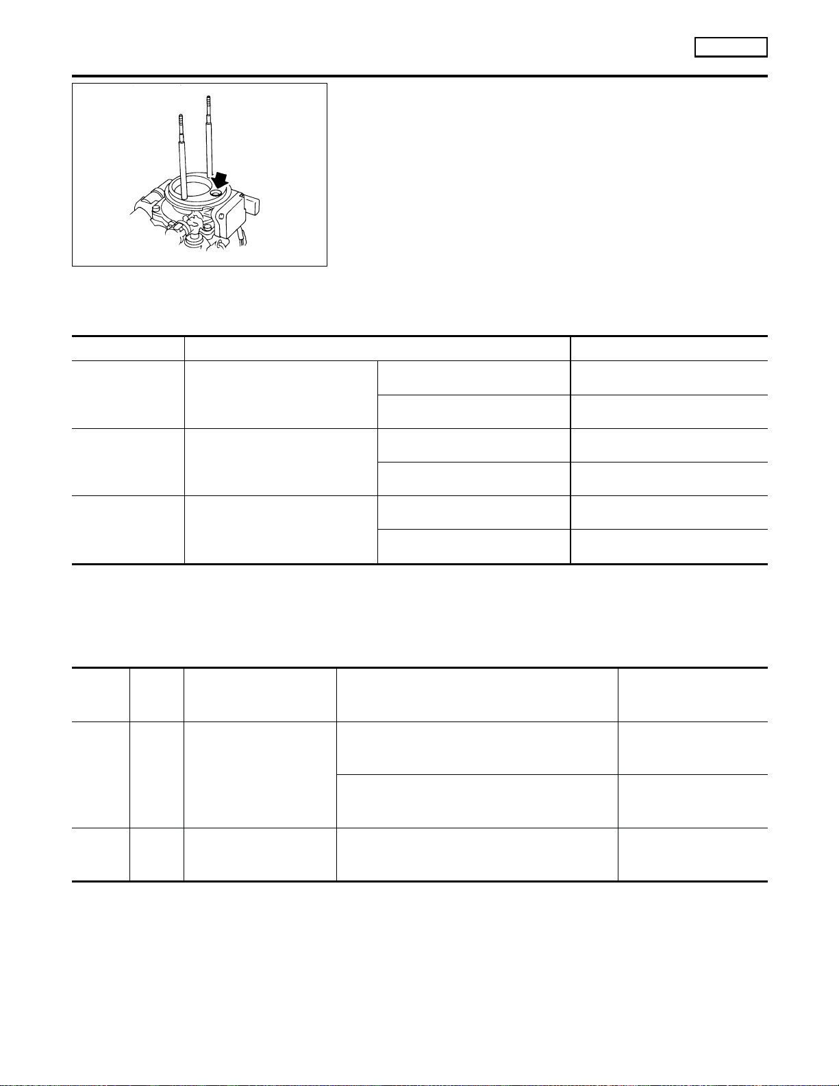
The mass air flow sensor is placed in the stream of intake air. It
measures the intake flow rate by measuring a part of the entire
intake flow. It consists of a hot wire that is supplied with electric
current from the ECM. The temperature of the hot wire is controlled
by the ECM a certain amount. The heat generated by the hot wire
is reduced as the intake air flows around it. The more air, the
greater the heat loss.
Therefore, the ECM must supply more electric current to maintain
the temperature of the hot wire as air flow increases. The ECM
detects the air flow by means of this current change.
CONSULT-II Reference Value in Data Monitor
Mode
NGEC0051
Specification data are reference values.
MONITOR ITEM CONDITION SPECIFICATION
MAS AIR/FL SE
쐌 Engine: After warming up
쐌 Air conditioner switch: OFF
쐌 Shift lever: “N”
쐌 No-load
Idle 0.9 - 1.8V
2,500 rpm 1.9 - 2.3V
CAL/LD VALUE
쐌 Engine: After warming up
쐌 Air conditioner switch: OFF
쐌 Shift lever: “N”
쐌 No-load
Idle 9.5 - 34.0%
2,500 rpm 13.9 - 24.9%
MASS AIRFLOW
쐌 Engine: After warming up
쐌 Air conditioner switch: OFF
쐌 Shift lever: “N”
쐌 No-load
Idle 0.9 - 5.8 g·m/s
2,500 rpm 7.5 - 13.2 g·m/s
ECM Terminals and Reference Value
NGEC0052
Specification data are reference values and are measured between each terminal and ground.
CAUTION:
Do not use ECM ground terminals when measuring input/output voltage. Doing so may result in dam-
age to the ECM’s transistor. Use a ground other than ECM terminals, such as the ground.
TERMI-
NAL
NO.
WIRE
COLOR
ITEM CONDITION DATA (DC Voltage)
54 R Mass air flow sensor
[Engine is running]
쐌 Warm-up condition
쐌 Idle speed
0.9 - 1.8V
[Engine is running]
쐌 Warm-up condition
쐌 Engine speed is 2,500 rpm
1.9 - 2.3V
55 G
Mass air flow sensor
ground
[Engine is running]
쐌 Warm-up condition
쐌 Idle speed
Approximately 0V
DTC P0100 MASS AIR FLOW SENSOR (MAFS)
KA24DE
Component Description
EC-150
Loading ...
Loading ...
Loading ...