Loading ...
Loading ...
Loading ...
ECM Terminals and Reference Value
=NGEC0597
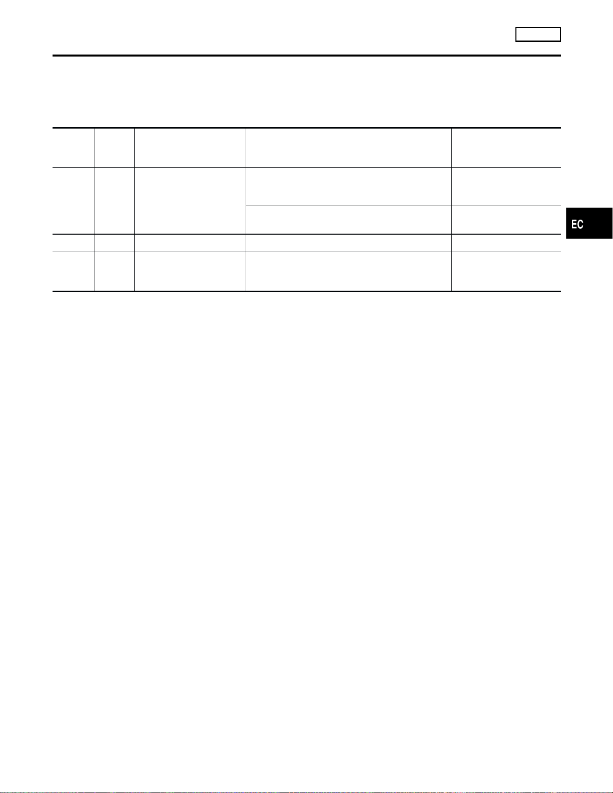
Specification data are reference values and are measured between each terminal and ground.
CAUTION:
Do not use ECM ground terminals when measuring input/output voltage. Doing so may result in dam-
age to the ECM’s transistor. Use a ground other than the ECM terminals, such as the ground.
TERMI-
NAL
NO.
WIRE
COLOR
ITEM CONDITION DATA (DC Voltage)
23 L Throttle position sensor
[Engine is running]
쐌 Warm-up condition
쐌 Accelerator pedal fully released
0.15 - 0.85V
[Ignition switch ON]
쐌 Accelerator pedal fully depressed
3.5 - 4.7V
42 B/W Sensors’ power supply [Ignition switch ON] Approximately 5V
43 BR Sensors’ ground
[Engine is running]
쐌 Warm-up condition
쐌 Idle speed
Approximately 0V
On Board Diagnosis Logic
NGEC0598
Malfunction is detected when
(Malfunction A) an excessively low or high voltage from the sensor
is sent to ECM,
(Malfunction B) a high voltage from the sensor is sent to ECM
under light load driving conditions,
(Malfunction C) a low voltage from the sensor is sent to ECM under
heavy load driving conditions.
POSSIBLE CAUSE
NGEC0598S01
Malfunction A
NGEC0598S0101
쐌 Harness or connectors
(The throttle position sensor circuit is open or shorted.)
쐌 Throttle position sensor
Malfunction B
NGEC0598S0102
쐌 Harness or connectors
(The throttle position sensor circuit is open or shorted.)
쐌 Throttle position sensor
쐌 Fuel injector
쐌 Camshaft position sensor
쐌 Mass air flow sensor
Malfunction C
NGEC0598S0103
쐌 Harness or connectors
(The throttle position sensor circuit is open or shorted.)
쐌 Intake air leaks
쐌 Throttle position sensor
FAIL-SAFE MODE
NGEC0598S02
When the malfunctionAis detected, the ECM enters fail-safe mode
and the MIL lights up.
DTC P0120 THROTTLE POSITION SENSOR
VG33E
ECM Terminals and Reference Value
EC-761
FE
CL
MT
AT
TF
PD
AX
SU
BR
ST
RS
BT
HA
SC
EL
IDX
GI
MA
EM
LC
Loading ...
Loading ...
Loading ...