Loading ...
Loading ...
Loading ...
4 CHECK GROUND CIRCUIT
1. Reconnect ECM harness connectors.
2. Check harness continuity between crankshaft position sensor (OBD) terminal 1 and engine ground. Refer to the wiring
diagram.
Continuity should exist.
3. Also check harness for short to power.
OK or NG
OK 䊳 GO TO 6.
NG 䊳 GO TO 5.
5 DETECT MALFUNCTIONING PART
Check the following.
쐌 Harness connectors E202, E32
쐌 Harness connectors E41, F25
쐌 Harness for open or short between crankshaft position sensor (OBD) and ECM
䊳 Repair open circuit or short to ground or short to power in harness or connectors.
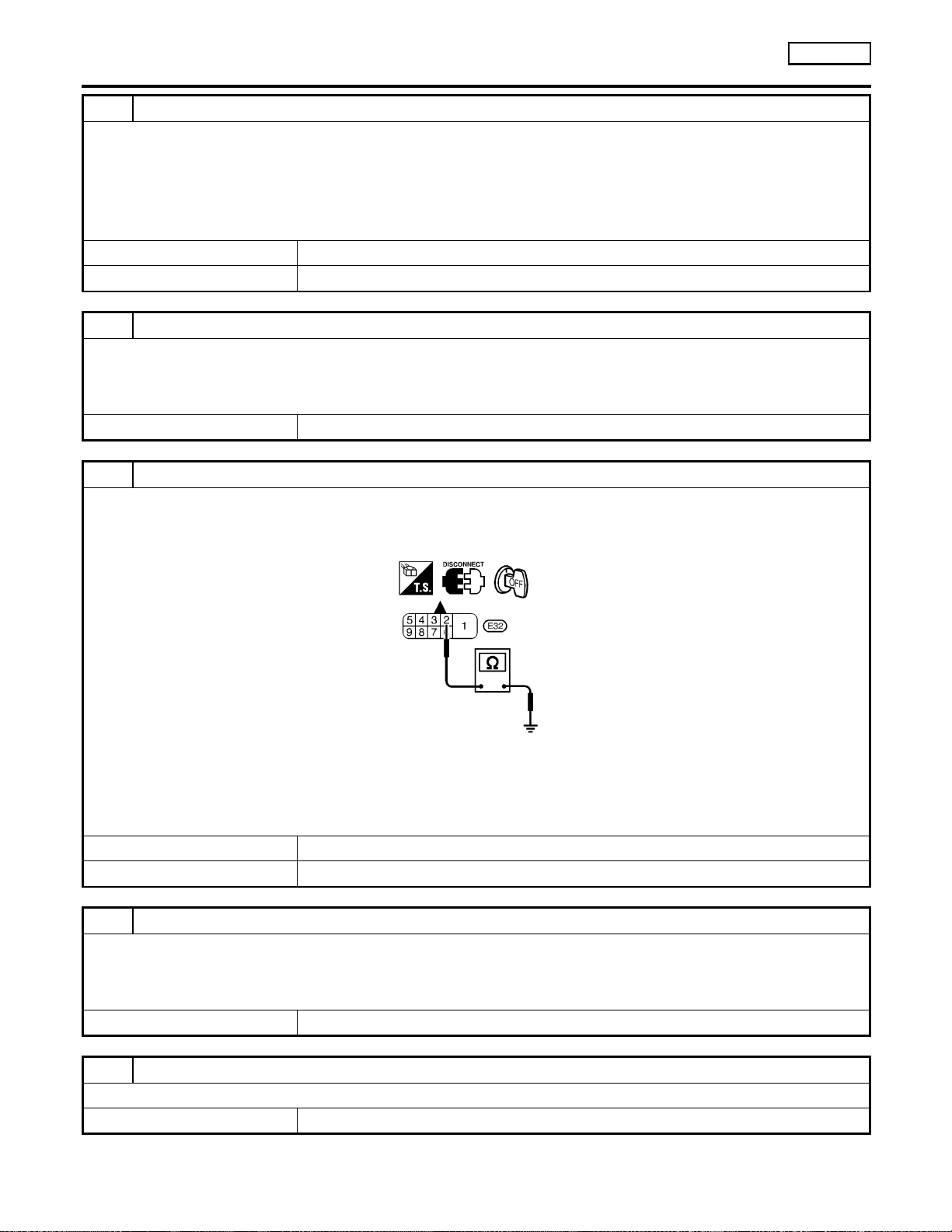
6 CHECK SHIELD CIRCUIT
1. Turn ignition switch OFF.
2. Disconnect harness connectors E32.
3. Check harness continuity between harness connector E32 terminal 2 and ground.
SEF552V
Continuity should exist
4. Also check harness for short to power.
5. Then reconnect harness connectors.
OK or NG
OK 䊳 GO TO 8.
NG 䊳 GO TO 7.
7 DETECT MALFUNCTIONING PART
Check the following.
쐌 Harness connectors E41, F25
쐌 Joint connector-1 (Refer to “HARNESS LAYOUT”, EL-254.)
쐌 Harness for open or short between harness connector E32 and engine ground
䊳 Repair open circuit or short to ground or short to power in harness or connectors.
8 CHECK IMPROPER INSTALLATION
Loosen and retighten the fixing bolt of the crankshaft position sensor (OBD). Then retest.
Trouble is not fixed. 䊳 GO TO 9.
DTC P1336 CRANKSHAFT POSITION SENSOR (CKPS)
(OBD) (COG)
KA24DE
Diagnostic Procedure (Cont’d)
EC-450
Loading ...
Loading ...
Loading ...