Loading ...
Loading ...
Loading ...
Operating the instrument
R&S
®
MXO 4 Series
48User Manual 1335.5337.02 ─ 05
1 = Time scale
2 = Horizontal position
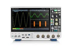
Figure 4-4: Acquisition label on the toolbar
1 = Sample rate
2 = Record length
3 = Acquisition mode
4 = Number of acquired waveforms
5 = Resolution
Info
The "Info" button on the toolbar points to the status messages of the instrument. To
open the message box, tap the button. See also: Chapter 4.10, "Instrument information
and notifications", on page 62.
Signal bar
The signal bar is the control center for all waveforms. All enabled waveforms are
shown on the left side of the signal bar. On the right side of the signal bar, you see the
signal activators of inactive waveforms. Tap a signal activator to enable the waveform.
Each waveform is represented by a signal icon. If the waveform is shown in a diagram,
the signal icon displays its main vertical and probe settings. If you tap a signal icon, the
dialog with vertical settings for this waveform opens. If you tap the "Minimize" icon on
the signal icon, the waveform switches from the diagram area to the signal icon: the
icon is grayed out. See Chapter 4.4, "Working with waveforms", on page 51 for a
detailed description.
In Figure 4-1, the signal icons C1, C2 and C3 show the main settings, and the wave-
forms are displayed in diagrams.
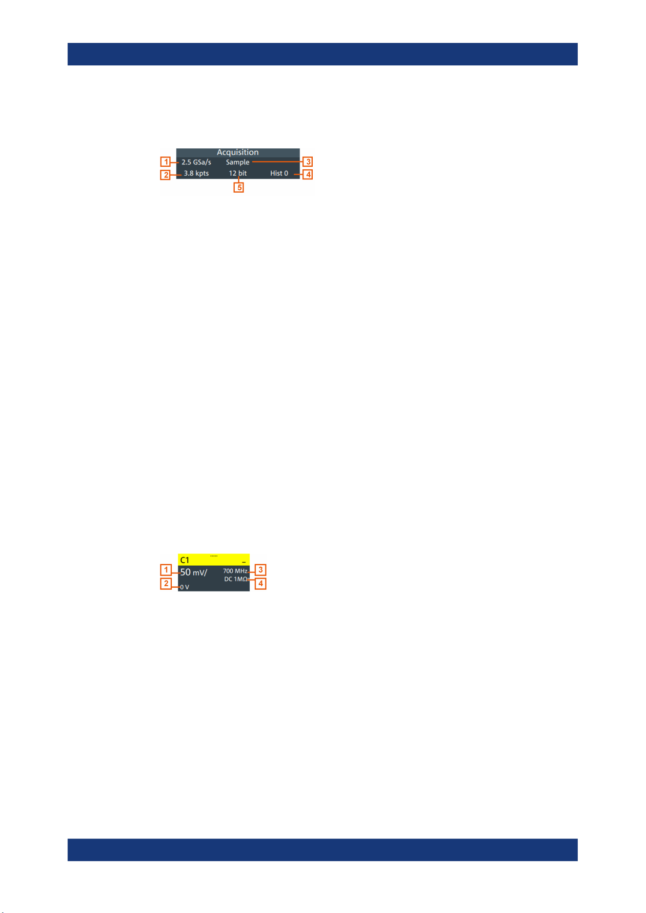
Figure 4-5: Signal label
1 = Vertical scale
2 = Offset
3 = Bandwidth
4 = Coupling and termination
If many waveforms are active, then waveforms of the same type are grouped in one
signal icon. Tap the group icon to open the individual signal icons.
Touchscreen display
Loading ...
Loading ...
Loading ...