Loading ...
Loading ...
Loading ...
Getting Started
R&S
®
MXO 4 Series
32User Manual 1335.5337.02 ─ 05
The maximum input voltage on channel inputs is:
●
400 V (V
p
) and 300 V (RMS) at 1 MΩ input impedance
●
30 V (V
p
) and 5 V (RMS) at 50 Ω input impedance
Trigger In
The external trigger input is a BNC connector that is used to control the measurement
by an external signal. The trigger level can be set from -5 V to 5 V.
For the external trigger input, the maximum input voltage is 400 V (V
p
) and
300 V (RMS) at 1 MΩ input impedance.
Transient overvoltages on all input connectors must not exceed 400 V (V
p
).
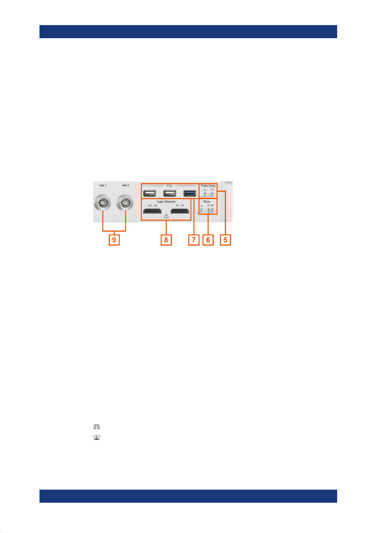
3.2.1.2 Other connectors on the front panel
Gen1, Gen2: Function generator
BNC output of the function generator, requires option R&S MXO4-B6.
Logic Channels
Two connectors for logical probes with 8 digital channels each (D0 to D7 and D8 to
D15). Using logic channels requires the Mixed Signal Option R&S MXO4-B1.
The maximum input voltage is 40 V (Vp) at 100 kΩ input impedance. The maximum
input frequency for a signal with the minimum input voltage swing and medium hystere-
sis of 800 mV (Vpp) is 400 MHz.
USB
Two USB 3.1 gen1 and one USB 2.0 high-speed interfaces type A . They are used to
connect a mouse or keyboard, a USB flash drive for storing and reloading instrument
settings and measurement data, and to update the firmware.
Demo
The pins are intended for demonstration purposes.
Probe Comp.
Probe compensation terminal to adjust passive probes to the oscilloscope channel.
Square wave signal for probe compensation.
Ground connector for probes.
Instrument tour
Loading ...
Loading ...
Loading ...