Loading ...
Loading ...
Loading ...
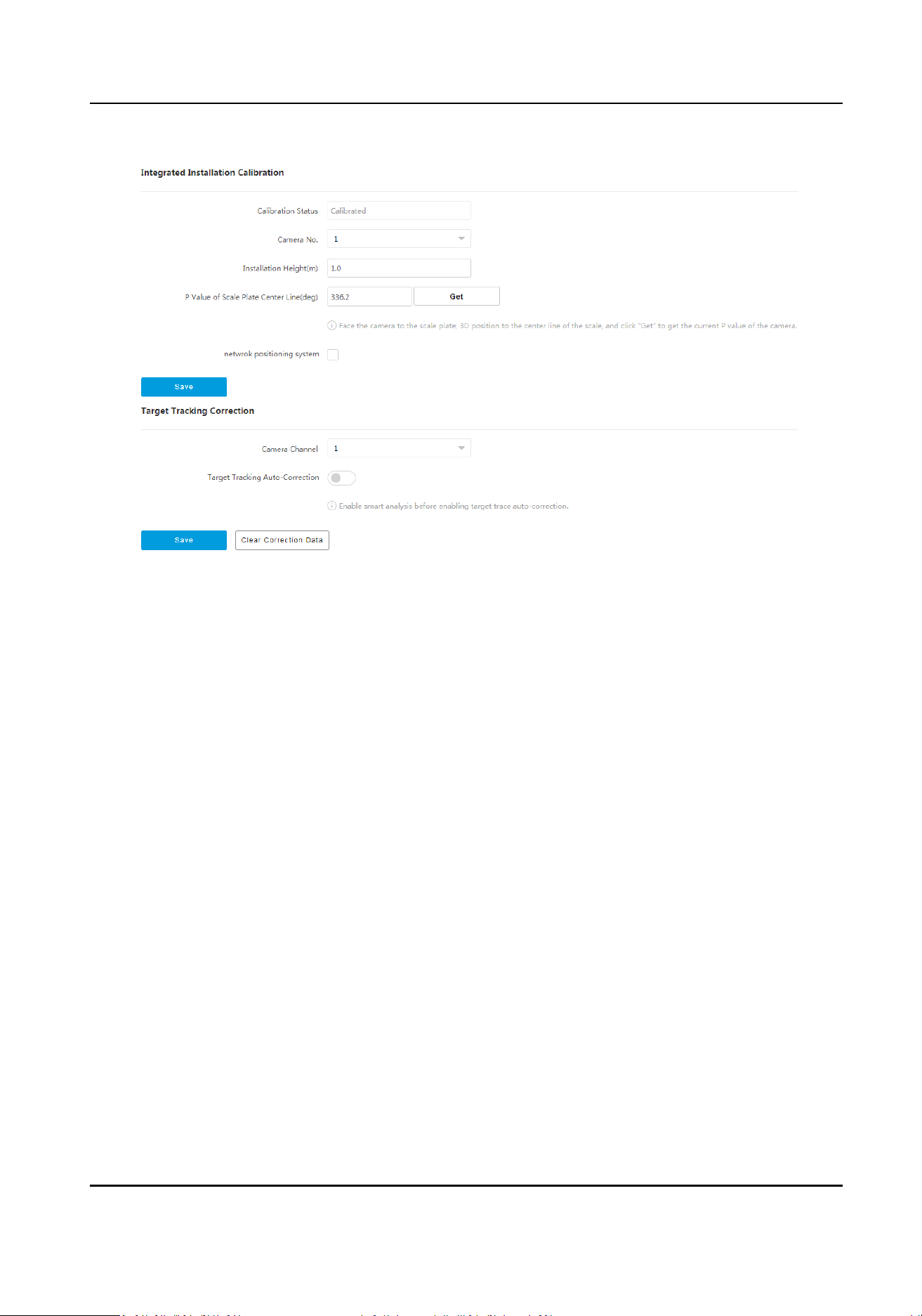
Figure 7-4 Camera Calibraon
2.
Set integrated installaon calibraon.
1) Select Camera No.
2) Enter
Installaon Height. It is the vercal height from the camera to the detecon surface.
3) Face the camera to the ruler, enlarge the image, enable 3D posioning, and click the center
line of the ruler, and the center of the live view image will be
automacally adjusted. Click Get
to get the P Value of Scale Plate Center Line.
4)
Oponal: For cameras installed with PTZ, check Network Posioning System.
5) Click Save.
3.
Set target tracking
correcon.
1) Select Camera Channel which has been enabled video content analysis.
2) Enable Target Tracking Auto-Correcon, and set the parameters.
Target Tracking
Auto-Correcon
When enabled, the target will be in the best posion in the live view image. The camera
will automacally adjust the lens to center the target. When the funcon is enabled, the
device will
connue to adapt to the terrain in the live view image according to each
judgment to achieve the best eect.
Sensivity Auto-Correcon
The higher the sensivity, the faster the adjustment, but the less the accuracy.
Save Auto-Correcon Data
Disabled by default. When enabled, the auto-corrected debug data and video data will be
packaged and stored to the SD card.
3) Click Save.
Security Radar User Manual
65
Loading ...
Loading ...
Loading ...