Loading ...
Loading ...
Loading ...
You can also enable the touch screen to set the trigger mode. Tap the trigger setting
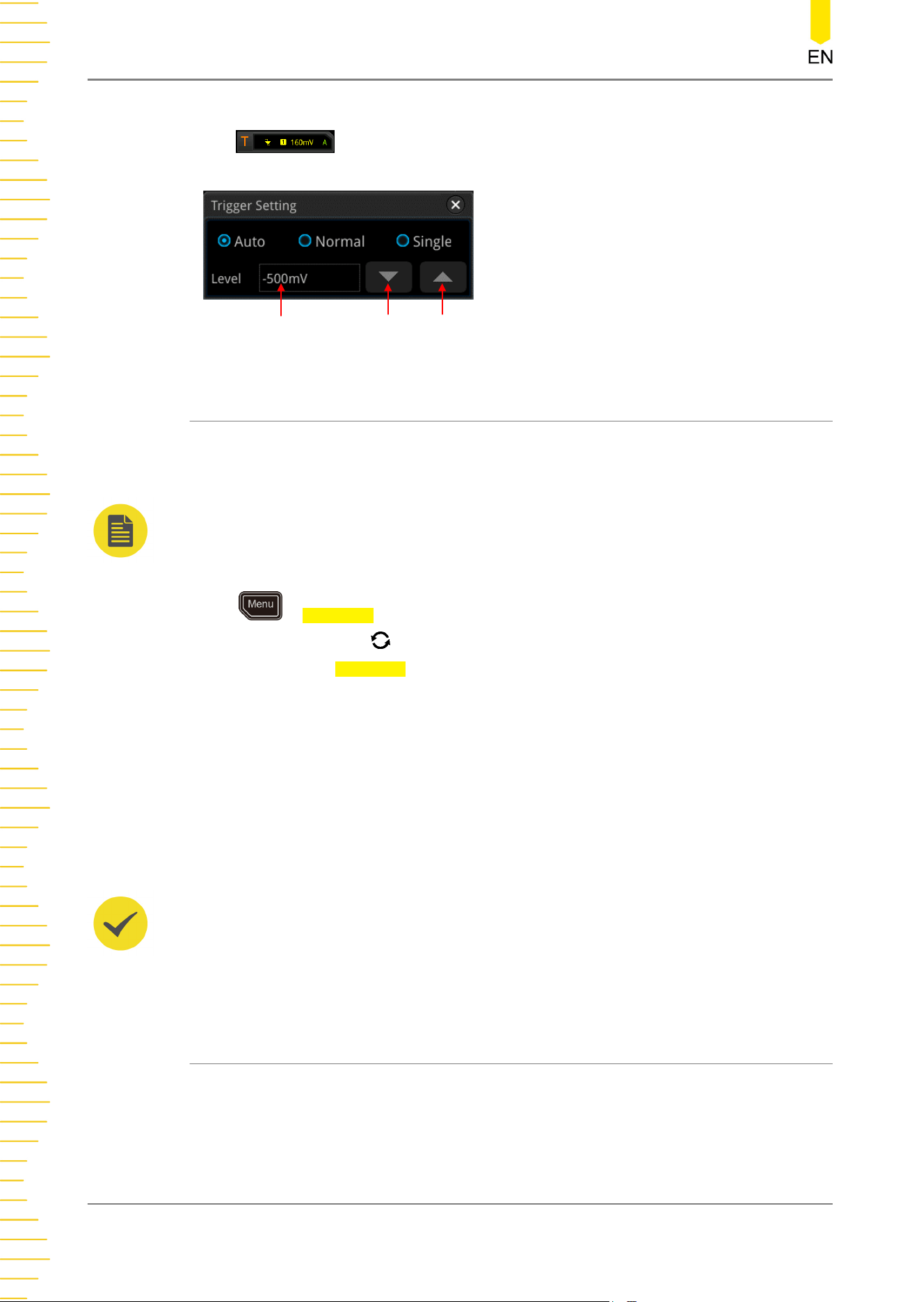
label at the upper-right corner of the screen. Then the following
window is displayed. Tap to select "Auto", "Normal", or "Single" as the trigger mode.
Level Input Field Decrease the level Increase the level
8.4 Trigger Coupling
Trigger coupling decides which kind of components will be transmitted to the trigger
module. Please distinguish trigger coupling from "
Channel Coupling
".
NOTE
Trigger coupling is only valid when the trigger type is Edge and the trigger source is an analog
channel.
Press
> Coupling in the trigger control area on the front panel, and then rotate
the multifunction knob to select the desired coupling mode (by default, it is DC).
You can also press Coupling key continuously or use the touch screen to select the
desired coupling mode.
• DC: allows DC and AC components to pass the trigger path.
• AC: blocks the DC components and attenuates signals.
• LFR: blocks the DC components and rejects the low-frequency components.
• HFR: rejects the high frequency components.
TIP
When "AC" or "LFR" is selected under Coupling, no trigger level lines and trigger icons are
displayed. When you adjust the trigger level, you can only see the changes of the trigger level
values at the upper-right corner of the screen.
8.5 Trigger Holdoff
Trigger holdoff can be used to stably trigger on complex repetitive waveforms that
have multiple edges (or other events) between waveform repetitions (such as pulse
series). Holdoff time indicates the time that the oscilloscope waits for re-arming the
trigger module after generating a correct trigger. The oscilloscope will not trigger
To Trigger the Oscilloscope
80
Copyright ©RIGOL TECHNOLOGIES CO., LTD. All rights reserved.
Loading ...
Loading ...
Loading ...