Loading ...
Loading ...
Loading ...
Analysis
R&S
®
RTC1000
78User Manual 1335.7352.02 ─ 04
Risk of electric shock
Make sure to discharge capacitors before test.
If components are tested which are located in circuits or instruments, make sure to set
the circuits or instruments currentless. If they are operated from the mains, also pull
out the mains plug of the test object. Thus, loops between the scope and the test
object via the safety earth are avoided, which can cause false results.
In component tester mode, the Y-preamplifiers and the timebase are disconnected.
Signals can be present at the inputs as long as the unit under test is not connected to
any circuit. It is possible to test components remaining in their circuits, but in such
cases all signals must be disconnected from the front panel BNC connectors (see
Chapter 6.7.1, "In-circuit Tests", on page 81).
The test principle is a generator within the R&S RTC1000 which generates a 50 Hz or
200 Hz (±10 %) sine wave. The sine wave feeds the series connection of the test
object and a sense resistor.
●
Is the test object short-circuited, the line is vertical (no voltage, current maximum).
●
If the test object is open-circuited or missing, a horizontal line appears (voltage, but
no current).
●
If the test object has only a real part such as a resistor, both voltages are in phase;
the display is a straight line, more or less slanted.
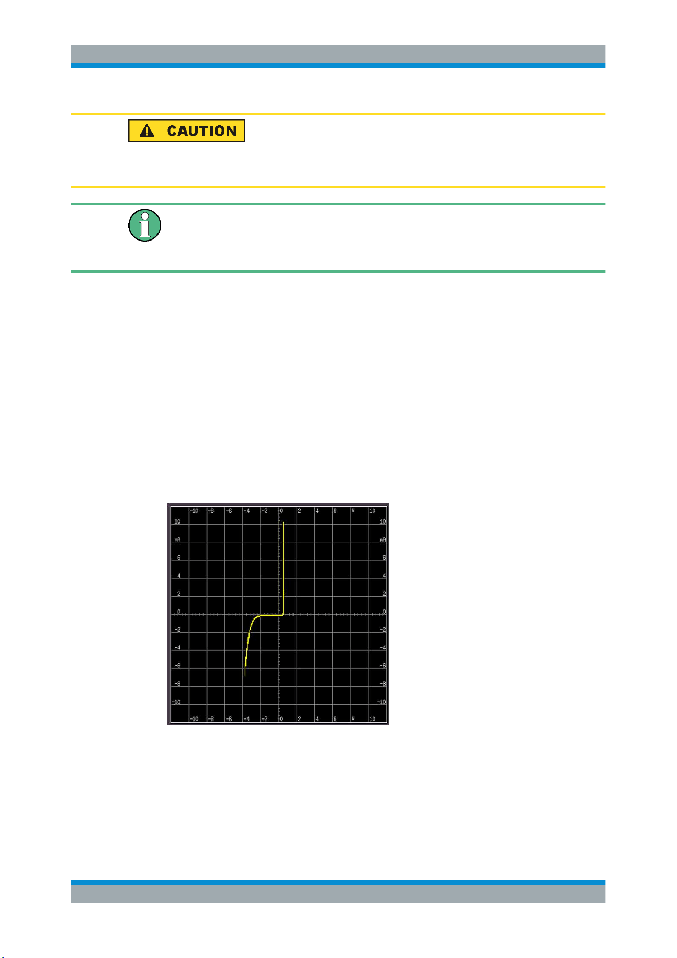
Figure 6-15: Component test example
The angle of the line is a measure of the resistance value. Resistor measurements
between Ω and kΩ are possible. Capacitors can be measured between μF and mF.
Capacitors and inductors cause phase shift between voltage and current and hence
between the voltages. The phase shift causes displays of ellipses. The location and the
Component Test
Loading ...
Loading ...
Loading ...