Loading ...
Loading ...
Loading ...
Waveform Setup
R&S
®
RTC1000
39User Manual 1335.7352.02 ─ 04
To perform probe compensation manually
1. Press the [UTIL] menu in the Vertical section.
2. Select the "PATTERN GEN." softkey.
3. Select "SQUARE WAVE" (see
Chapter 10.2.1, "Square Wave", on page 115).
4. Use the compensation trimmer of the probe to get optimum square wave response.
For details, refer to the documentation of your probe.
4.2 Horizontal Setup
Horizontal settings, also known as timebase settings, adjust the waveforms in horizon-
tal direction.
Typically, the trigger is the determining point of the waveform record. In many scenar-
ios, you want to analyze the waveform some time before or after the trigger. To adjust
the horizontal acquisition window to the waveform section of interest, you can use the
following parameters:
●
The trigger position (horizontal position) defines the time distance of the trigger
point to the reference point. Changing the trigger position, you can move the trigger
point, even outside the screen.
●
The reference point is the zero point of the diagram and the rescaling center of
the time scale on the screen. If you modify the time scale, the reference point
remains fixed on the screen, and the scale is stretched or compressed to both
sides of the reference point.
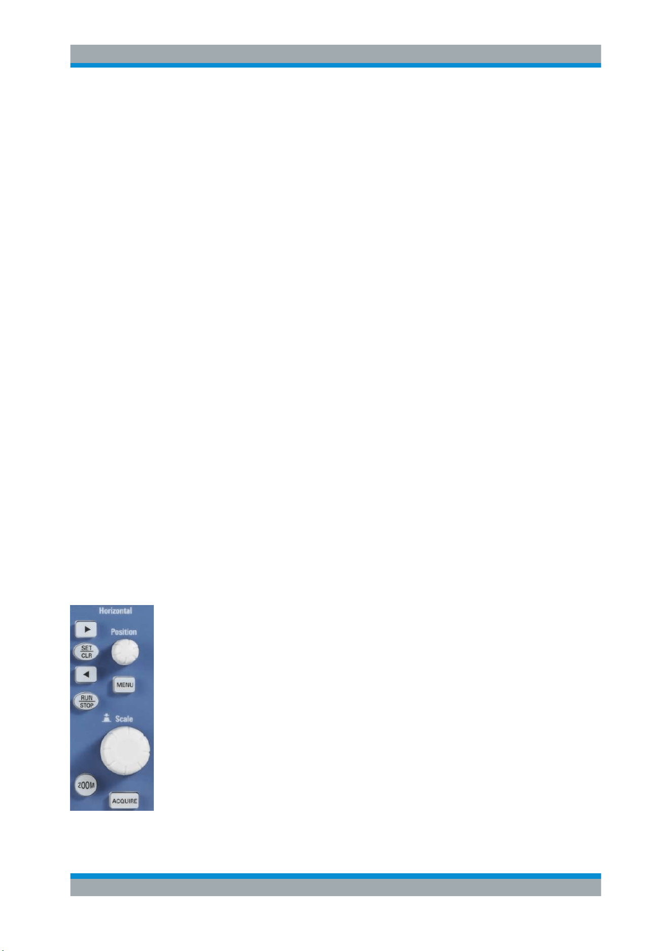
In the HORIZONTAL section of the front panel, you can:
●
Adjust the timebase, trigger position, and acquisition settings, see
"To adjust time-
base and trigger position"
on page 39.
●
Activate the zoom, see
Chapter 6.1, "Zoom Function", on page 58.
●
Set markers, see
Chapter 6.2, "Marker Function", on page 60.
To adjust timebase and trigger position
1. To set the timebase (horizontal scale), turn the [Scale] knob in the Horizontal sec-
tion.
The current timebase setting, e.g."TB: 500 ns", is displayed in the upper left above
the grid. The default setting shows the trigger in the center of the display, with 50%
of the signal display before and 50% after this trigger position.
2. To set the trigger position, use one of these methods:
● Turn the [Position] knob.
● Use the arrow keys.
● Press the [MENU] key.
In the submenu, you can:
– Set an exact value: "NUMERIC INPUT"
Horizontal Setup
Loading ...
Loading ...
Loading ...