Loading ...
Loading ...
Loading ...
Getting Started
R&S
®
RTC1000
17User Manual 1335.7352.02 ─ 04
Logic probe (9)
The connector for logic channels can be used if the Mixed Signal Option R&S RTC-B1
is installed. The option provides a logical probe with 8 digital channels (D0 to D7).
The maximum input voltage is 40 V (peak) at 100 kΩ input impedance. The maximum
input frequency for a signal with the minimum input voltage swing and medium hystere-
sis of 800 mV (Vpp) is 300 MHz.
Risk of instrument damage
Use the connector for the active logic probe exclusively for the logic probe R&S RT-
ZL03, which is delivered with option R&S RTC-B1. Connecting other probe types can
demolish the input.
2.2.1.2 Other Connectors on the Front Panel
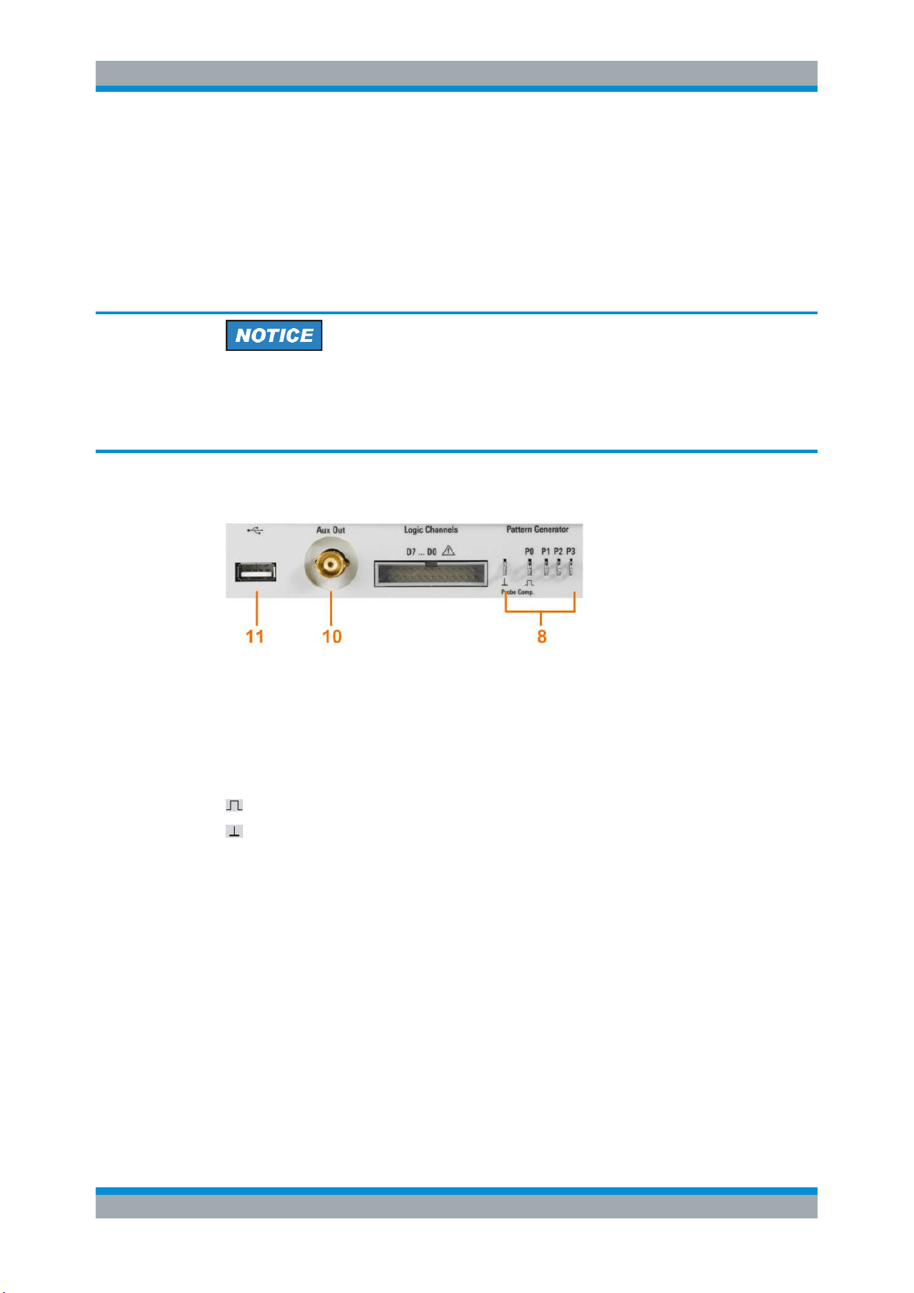
[Pattern Generator] (8)
Connectors for the pattern generator P0, P1, P2, P3.
[Probe Comp.] (8)
Probe compensation terminal to support adjustment of passive probes to the oscillo-
scope channel.
Square wave signal for probe compensation.
Ground connector for probes.
[Aux Out] (10)
Multi-purpose BNC output that can function as pass/fail and trigger output, output for
component testing, and as function generator output (with option R&S RTC-B6).
[USB] type A (11)
USB 2.0 type A interface to connect a USB flash drive for storing and reloading instru-
ment settings and measurement data, and to update the firmware.
2.2.2 Rear Panel
Figure 2-2 shows the rear panel of the R&S RTC1000 with its connectors.
Instrument Tour
Loading ...
Loading ...
Loading ...