Loading ...
Loading ...
Loading ...
Serial Bus Analysis
R&S
®
RTC1000
131User Manual 1335.7352.02 ─ 04
present, the select line can be deleted. This type of line is also called SSPI (Simple
SPI) (2-wire).
An SPI bus has the following properties:
●
Master-slave communication
●
No instrument addressing
●
No acknowledge to confirm data reception
●
Duplex capability
Most SPI buses have four common lines, two data lines and two control lines:
●
Clock to all slaves (SCLK)
●
Slave select or chip select lines (SS or CS)
●
Master-Out-Slave-In, Slave-Data-Input (MOSI or SDI)
●
Master-In-Slave-Out, Slave-Data-Output (MISO or SDO)
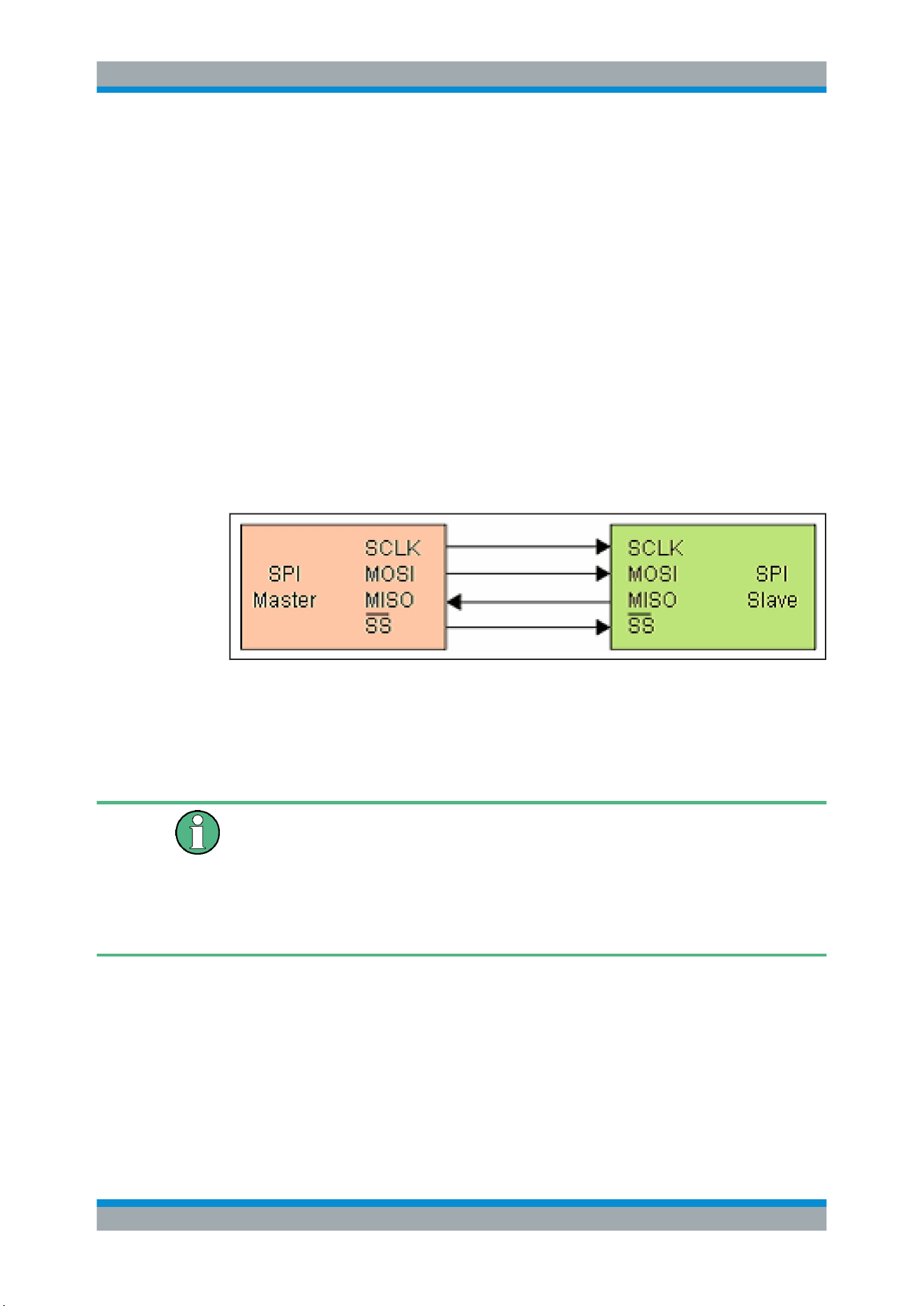
If the master generates a clock pulse and selects a slave, data can be transmitted in
either one direction or simultaneously in both directions.
Figure 11-7: Simple configuration of SPI bus
11.4.1 SPI / SSPI Bus Configuration
Before you configure the bus, set the correct logic level (threshold).
●
For analog channels, see
"THRESHOLD menu" on page 36.
●
For digital channels, see
"To set the threshold for logic states" on page 108. The
default value is 500 mV.
For 3-wire SPI, the external trigger input is used as CS (Chip Select). The threshold
can be set in the bus configuration menu.
To select the SPI or SSPI bus
1. Press the [BUS] key in the Vertical section.
2. In the short menu, select the bus: "B1" or "B2".
3. In the "BUS" menu, press the "BUS TYPE" softkey.
4. Use the [Universal] knob to select:
● "SSPI" for a 2-wire SPI system.
SPI / SSPI BUS (Option R&S RTC-K1)
Loading ...
Loading ...
Loading ...