Loading ...
Loading ...
Loading ...
Mixed Signal Operation (Option R&S RTC-B1)
R&S
®
RTC1000
108User Manual 1335.7352.02 ─ 04
●
"To label the individual bits of the logic probe" on page 109
To set the threshold for logic states
1. Press the [POD] key.
2. Press the [MENU] key in the Vertical section.
3. Set "SETUP" = "POD".
4. Press "THRESHOLD".
5. Set the threshold:
● Select the predefined level for "TTL", "CMOS" or "ECL".
● To set a user-defined level, select "User1" or "User2".
Adjust the logic level from –2 V to 8 V with the universal knob or the [KEYPAD]
key.
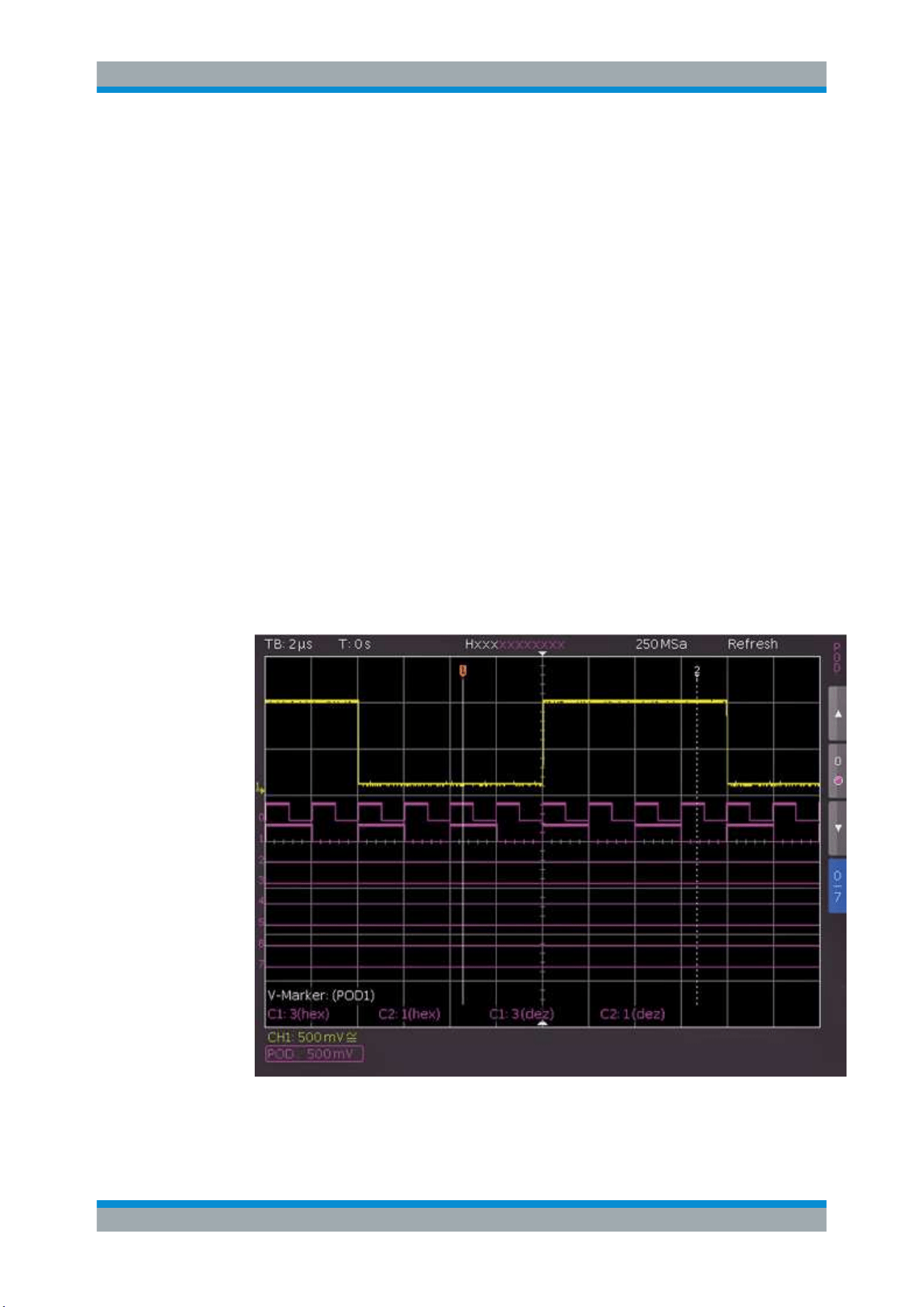
To activate and scale logic channels
1. To switch on the digital channels, press the [POD] key in the Vertical section.
The digital channels 0 to 7 are shown on the screen. A logic "1" is indicated by a
bar that is two pixels wide, and a logic "0" is indicated by a bar that is one pixel
wide. The logic threshold and a figure which shows the logical states are shown
next to the name "POD" in the information field in the bottom left of the display.
Figure 9-2: Logic channels: display settings
Using Logic Channels
Loading ...
Loading ...
Loading ...