Loading ...
Loading ...
Loading ...
Serial Bus Analysis
R&S
®
RTC1000
147User Manual 1335.7352.02 ─ 04
Table 11-4: Content of the CAN bus table
Column Description
"Start Time" Time of frame start in relation to the trigger point
"Type"
Frame type:
●
"DATA" = Data frame
●
"REMOTE" = Remote frame
●
"ERR-F." = Transmission error (error frame)
●
"OVL-F." = Overload frame
"ID" Frame ID
"DLC" Data length code, number of data bytes
"Data" Values of the data bytes
"CRC" Cyclic Redundancy Check
"State"
Frame state:
●
"OK" = frame is valid
●
"CRC" = the calculated result deviates from the received CRC sequence (cyclic
redundancy check failed)
●
"NACK" = no acknowledge
●
"CRC+NACK" = cyclic redundancy check failed followed by "not acknowledge"
●
"STUFF" = Bit stuffing error
●
"INS" = the frame is not contained in the acquisition; the acquired part of the
frame is valid.
11.7 LIN Bus (Option R&S RTC-K3)
For CAN bus trigger and decoding, you need the R&S RTC-K3 option.
The LIN bus (Local Interconnect Network) is a simple master/slave bus system for
automotive applications and is used for the data exchange between controller units
and sensors or actuators. The signal is transmitted on one line with ground reference
to the vehicle mass.
A LIN bus has the following properties:
●
Serial single-wire communication protocol (byte-oriented)
●
Master-slave communication (up to 12 knots)
●
Master-controlled communication (master initiates / coordinates communication)
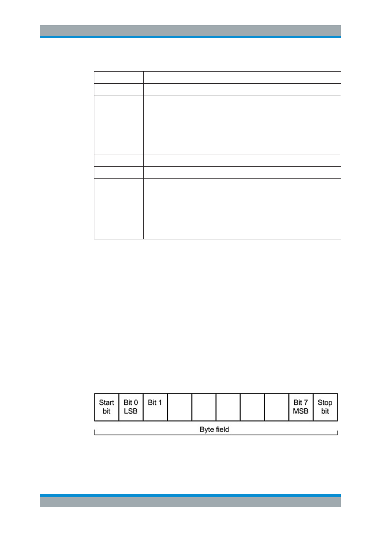
The data is transmitted in bytes without parity (based on UART). Each byte consists of
a start bit, 8 data bits, and a stop bit.
Figure 11-18: LIN byte structure
LIN Bus (Option R&S RTC-K3)
Loading ...
Loading ...
Loading ...