Loading ...
Loading ...
Loading ...
DGS-1520 Series Gigabit Ethernet Smart Managed Switch Web UI Reference Guide
313
Click the Show All button to display all the entries.
Enter a page number and click the Go button to navigate to a specific page when multiple pages exist.
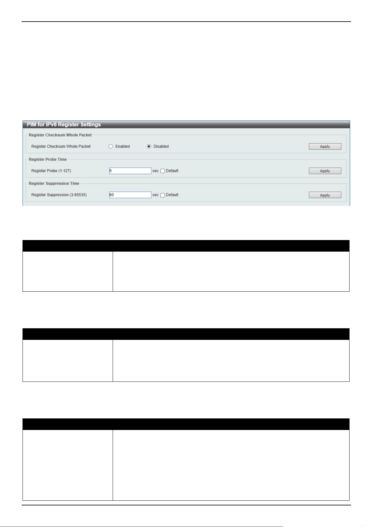
PIM for IPv6 Register Settings
This window is used to display and configure the IPv6 PIM register settings.
To view the following window, click L3 Features > IP Multicast Routing Protocol > PIM > PIM for IPv6 > PIM for
IPv6 Register Settings, as shown below:
Figure 6-113 PIM for IPv6 Register Settings Window
The fields that can be configured in Register Checksum Whole Packet are described below:
Parameter Description
Register Checksum Whole
Packet
Select the enable or disable the register checksum whole-packet feature here.
When enabled, it configures the router to calculate the checksum of register
message over the entire PIM message including the data portion. By default, the
register checksum methodology is PIM RFC-compliant, excluding the data portion
in the Register message.
Click the Apply button to accept the changes made.
The fields that can be configured in Register Probe Time are described below:
Parameter Description
Register Probe
Enter the register probe time value here. The range is from 1 to 127 seconds. The
register-probe time is the time before the Register-Stop Timer (RST) expires when
a DR may send a Null-Register to the RP to cause it to resend a Register-Stop
message. By default, this value is 5 seconds.
Select the Default option to use the default value.
Click the Apply button to accept the changes made.
The fields that can be configured in Register Suppression Time are described below:
Parameter Description
Register Suppression
Enter the register suppression timeout value here. The range is from 3 to 65535
seconds. When a DR receives the register-stop message, it will start the
suppression timer. During the suppression time, a DR will stop sending Register-
encapsulated data to the RP. This timer should be configured on the designated
router. The value of the Register Probe Time must be less than half the value of
the Register Suppression Time to prevent a possible negative value in the setting
of the Register-Stop Timer. The minimal value for Register Suppression Time is 3.
By default, this value is 60 seconds.
Select the Default option to use the default value.
Loading ...
Loading ...
Loading ...