DGS-1520 Series Gigabit Ethernet Smart Managed Switch
Web UI Reference Guide

Information in this document is subject to change without notice. Reproduction in any manner whatsoever, without the written
permission of D-Link Corporation, is strictly forbidden.
Trademarks used in this text: D-Link and the D-LINK logo are trademarks of D-Link Corporation; Microsoft and Windows are
registered trademarks of Microsoft Corporation.
Other trademarks and trade names may be used in this document to refer to either the entities claiming the marks and names or
their products. D-Link Corporation disclaims any proprietary interest in trademarks and trade names other than its own.
© 2020 D-Link Corporation. All rights reserved.
FCC Compliance Statement
This device complies with Part 15 of the FCC Rules. Operation is subject to the following two conditions: (1) This device may not
cause harmful interference, and (2) this device must accept any interference received, including interference that may cause
undesired operation.
D-Link Corporate
17595 Mt. Hermann Street
Fountain Valley, CA 92708
(800) 326-1688
CE Mark Warning
This equipment is compliant with Class A of CISPR 32. In a residential environment, this equipment may cause radio interference.
Avertissement Concernant la Marque CE
Cet équipement est conforme à la classe A de la norme CISPR 32. Dans un environnement résidentiel, cet équipement peut
provoquer des interférences radio.
VCCI Warning
この装置は、クラス A 機器です。この装置を住宅環境で使用すると電波妨害を引き起こすことがあります。この場合には使用者が
適切な対策を講ずるよう要求されることがあります。 VCCI-A
BSMI Notice
此為甲類資訊技術設備,於居住環境中使用時,可能會造成射頻擾動,在此種情況下,使用者會被要求採取某些適當的對策。
Safety Compliance
Warning: Class 1 Laser Product: When using a fiber optic media expansion module, never look at the transmit laser while it is
powered on. In addition, never look directly at the fiber TX port and fiber cable ends when they are powered on.
Avertissement: Produit Laser de Classe 1: Ne regardez jamais le laser tant qu'il est sous tension. Ne regardez jamais
directement le port TX (Tramsmission) à fibres optiques et les embouts de câbles à fibres optiques tant qu'ils sont sous tension.

DGS-1520 Series Gigabit Ethernet Smart Managed Switch Web UI Reference Guide
i
Table of Contents
1. Introduction ........................................................................................................................................................... 1
Audience ................................................................................................................................................................. 1
Other Documentation .............................................................................................................................................. 1
Typographical Conventions .................................................................................................................................... 1
Notes and Cautions ................................................................................................................................................ 1
2. Web User Interface (Web UI)................................................................................................................................ 2
Connecting to the Web UI ....................................................................................................................................... 2
Logging into the Web UI ......................................................................................................................................... 2
Smart Wizard .......................................................................................................................................................... 3
Step 1 - System IP Information.......................................................................................................................... 3
Step 2 - User Accounts Settings ....................................................................................................................... 4
Step 3 - SNMP Settings ..................................................................................................................................... 5
Web Interface Navigation ....................................................................................................................................... 6
3. System ................................................................................................................................................................... 7
Device Information .................................................................................................................................................. 7
System Information Settings ................................................................................................................................... 8
Peripheral Settings ................................................................................................................................................. 9
Port Configuration ................................................................................................................................................. 10
Port Settings .................................................................................................................................................... 10
Port Status ....................................................................................................................................................... 12
Port GBIC ........................................................................................................................................................ 12
Port Auto Negotiation ...................................................................................................................................... 13
Error Disable Settings ...................................................................................................................................... 14
Jumbo Frame .................................................................................................................................................. 15
Interface Description ............................................................................................................................................. 16
Loopback Test ...................................................................................................................................................... 16
PoE ....................................................................................................................................................................... 17
PoE System ..................................................................................................................................................... 18
PoE Status ....................................................................................................................................................... 19
PoE Configuration ........................................................................................................................................... 19
PD Alive ........................................................................................................................................................... 21
PoE Statistics .................................................................................................................................................. 22
PoE Measurement ........................................................................................................................................... 22
PoE LLDP Classification .................................................................................................................................. 23
System Log ........................................................................................................................................................... 24
System Log Settings ........................................................................................................................................ 24
System Log Discriminator Settings ................................................................................................................. 26
System Log Server Settings ............................................................................................................................ 27
System Log ...................................................................................................................................................... 28
System Attack Log ........................................................................................................................................... 29
Time and SNTP .................................................................................................................................................... 29
Clock Settings .................................................................................................................................................. 29
Time Zone Settings ......................................................................................................................................... 30
SNTP Settings ................................................................................................................................................. 31
Time Range .......................................................................................................................................................... 32
Reset Button Settings ........................................................................................................................................... 33
4. Management ........................................................................................................................................................ 34
Command Logging ............................................................................................................................................... 34
User Accounts Settings ........................................................................................................................................ 35

DGS-1520 Series Gigabit Ethernet Smart Managed Switch Web UI Reference Guide
ii
Password Encryption ............................................................................................................................................ 36
Password Recovery .............................................................................................................................................. 37
Login Method ........................................................................................................................................................ 37
SNMP .................................................................................................................................................................... 39
SNMP Global Settings ..................................................................................................................................... 40
SNMP Linkchange Trap Settings .................................................................................................................... 41
SNMP View Table Settings ............................................................................................................................. 42
SNMP Community Table Settings ................................................................................................................... 42
SNMP Group Table Settings ........................................................................................................................... 44
SNMP Engine ID Local Settings ...................................................................................................................... 45
SNMP User Table Settings.............................................................................................................................. 45
SNMP Host Table Settings .............................................................................................................................. 47
SNMP Context Mapping Table Settings .......................................................................................................... 48
RMON ................................................................................................................................................................... 48
RMON Global Settings .................................................................................................................................... 48
RMON Statistics Settings ................................................................................................................................ 49
RMON History Settings ................................................................................................................................... 50
RMON Alarm Settings ..................................................................................................................................... 51
RMON Event Settings ..................................................................................................................................... 52
Telnet/Web............................................................................................................................................................ 53
Session Timeout ................................................................................................................................................... 53
DHCP .................................................................................................................................................................... 54
Service DHCP ................................................................................................................................................. 54
DHCP Class Settings ...................................................................................................................................... 55
DHCP Pool Settings ........................................................................................................................................ 56
DHCP Server ................................................................................................................................................... 56
DHCPv6 Server ............................................................................................................................................... 64
DHCP Relay .................................................................................................................................................... 70
DHCPv6 Relay ................................................................................................................................................ 77
DHCP Auto Configuration ..................................................................................................................................... 85
DHCP Auto Image Settings .................................................................................................................................. 85
DNS ...................................................................................................................................................................... 86
DNS Global Settings ........................................................................................................................................ 87
DNS Name Server Settings ............................................................................................................................. 87
DNS Host Settings ........................................................................................................................................... 88
NTP ....................................................................................................................................................................... 89
NTP Global Settings ........................................................................................................................................ 89
NTP Server Settings ........................................................................................................................................ 90
NTP Peer Settings ........................................................................................................................................... 91
NTP Access Group Settings ............................................................................................................................ 91
NTP Key Settings ............................................................................................................................................ 93
NTP Interface Settings .................................................................................................................................... 94
NTP Associations ............................................................................................................................................ 94
NTP Status ...................................................................................................................................................... 95
IP Source Interface ............................................................................................................................................... 96
File System ........................................................................................................................................................... 96
Stacking ................................................................................................................................................................ 98
Physical Stacking .......................................................................................................................................... 102
Stacking Bandwidth ....................................................................................................................................... 103
Virtual Stacking (SIM) ......................................................................................................................................... 104
Single IP Settings .......................................................................................................................................... 106
Topology ........................................................................................................................................................ 108

DGS-1520 Series Gigabit Ethernet Smart Managed Switch Web UI Reference Guide
iii
Firmware Upgrade ......................................................................................................................................... 113
Configuration File Backup/Restore ................................................................................................................ 113
Upload Log File ............................................................................................................................................. 114
D-Link Discovery Protocol .................................................................................................................................. 114
DDP Settings ................................................................................................................................................. 114
DDP Neighbors .............................................................................................................................................. 115
SMTP Settings .................................................................................................................................................... 116
NLB FDB Settings ............................................................................................................................................... 117
5. Layer 2 Features ............................................................................................................................................... 119
FDB ..................................................................................................................................................................... 119
Static FDB...................................................................................................................................................... 119
MAC Address Table Settings ........................................................................................................................ 120
MAC Address Table ...................................................................................................................................... 122
MAC Notification ............................................................................................................................................ 123
VLAN ................................................................................................................................................................... 124
VLAN Configuration Wizard........................................................................................................................... 124
802.1Q VLAN ................................................................................................................................................ 127
VLAN Interface .............................................................................................................................................. 128
802.1v Protocol VLAN ................................................................................................................................... 133
GVRP ............................................................................................................................................................. 135
Asymmetric VLAN ......................................................................................................................................... 139
MAC VLAN .................................................................................................................................................... 140
L2VLAN Interface Description ....................................................................................................................... 140
Subnet VLAN ................................................................................................................................................. 141
Super VLAN ................................................................................................................................................... 141
Auto Surveillance VLAN ................................................................................................................................ 143
Voice VLAN ................................................................................................................................................... 146
Private VLAN ................................................................................................................................................. 149
VLAN Tunnel ...................................................................................................................................................... 150
Dot1q Tunnel ................................................................................................................................................. 150
VLAN Mapping .............................................................................................................................................. 152
VLAN Mapping Profile ................................................................................................................................... 154
STP ..................................................................................................................................................................... 159
STP Global Settings ...................................................................................................................................... 161
STP Port Settings .......................................................................................................................................... 163
MST Configuration Identification ................................................................................................................... 165
STP Instance ................................................................................................................................................. 166
MSTP Port Information .................................................................................................................................. 166
ERPS (G.8032) ................................................................................................................................................... 167
ERPS ............................................................................................................................................................. 167
ERPS Profile .................................................................................................................................................. 172
Loopback Detection ............................................................................................................................................ 173
Link Aggregation ................................................................................................................................................. 175
L2 Protocol Tunnel .............................................................................................................................................. 178
L2 Multicast Control ............................................................................................................................................ 179
IGMP Snooping ............................................................................................................................................. 179
MLD Snooping ............................................................................................................................................... 188
Multicast VLAN .............................................................................................................................................. 198
PIM Snooping ................................................................................................................................................ 203
Multicast Filtering Mode ................................................................................................................................. 205
LLDP ................................................................................................................................................................... 206
LLDP Global Settings .................................................................................................................................... 206

DGS-1520 Series Gigabit Ethernet Smart Managed Switch Web UI Reference Guide
iv
LLDP Port Settings ........................................................................................................................................ 207
LLDP Management Address List ................................................................................................................... 208
LLDP Basic TLVs Settings ............................................................................................................................ 209
LLDP Dot1 TLVs Settings.............................................................................................................................. 210
LLDP Dot3 TLVs Settings.............................................................................................................................. 211
LLDP-MED Port Settings ............................................................................................................................... 212
LLDP Statistics Information ........................................................................................................................... 213
LLDP Local Port Information ......................................................................................................................... 214
LLDP Neighbor Port Information ................................................................................................................... 215
6. Layer 3 Features ............................................................................................................................................... 218
ARP ..................................................................................................................................................................... 218
ARP Aging Time ............................................................................................................................................ 218
Static ARP ..................................................................................................................................................... 219
Proxy ARP ..................................................................................................................................................... 220
ARP Table ..................................................................................................................................................... 220
Gratuitous ARP ................................................................................................................................................... 221
IPv6 Neighbor ..................................................................................................................................................... 222
Interface .............................................................................................................................................................. 223
IPv4 Interface ................................................................................................................................................ 223
IPv6 Interface ................................................................................................................................................ 226
Loopback Interface ........................................................................................................................................ 230
Null Interface ................................................................................................................................................. 231
UDP Helper ......................................................................................................................................................... 232
IP Forward Protocol ....................................................................................................................................... 232
IP Helper Address ......................................................................................................................................... 232
IPv4 Static/Default Route .................................................................................................................................... 233
IPv4 Route Table ................................................................................................................................................ 234
IPv6 Static/Default Route .................................................................................................................................... 235
IPv6 Route Table ................................................................................................................................................ 236
Route Preference ................................................................................................................................................ 237
ECMP Settings ................................................................................................................................................... 237
IPv6 General Prefix ............................................................................................................................................. 238
URPF Settings .................................................................................................................................................... 238
RIP ...................................................................................................................................................................... 240
RIP Settings ................................................................................................................................................... 240
RIP Distribute List .......................................................................................................................................... 242
RIP Interface Settings .................................................................................................................................... 242
RIP Database ................................................................................................................................................ 244
RIPng .................................................................................................................................................................. 245
RIPng Settings ............................................................................................................................................... 245
RIPng Interface Settings ................................................................................................................................ 246
RIPng Database ............................................................................................................................................ 247
OSPF .................................................................................................................................................................. 248
OSPFv2 ......................................................................................................................................................... 248
OSPFv3 ......................................................................................................................................................... 263
IP Multicast Routing Protocol.............................................................................................................................. 277
IGMP .............................................................................................................................................................. 277
MLD ............................................................................................................................................................... 280
IGMP Proxy ................................................................................................................................................... 283
MLD Proxy ..................................................................................................................................................... 286
DVMRP .......................................................................................................................................................... 288
PIM ................................................................................................................................................................ 290

DGS-1520 Series Gigabit Ethernet Smart Managed Switch Web UI Reference Guide
v
IPMC .............................................................................................................................................................. 325
IPv6MC .......................................................................................................................................................... 331
IP Route Filter ..................................................................................................................................................... 333
Route Map ..................................................................................................................................................... 333
Policy Route ........................................................................................................................................................ 337
VRRP Settings .................................................................................................................................................... 337
VRRPv3 Settings ................................................................................................................................................ 340
7. Quality of Service (QoS) ................................................................................................................................... 343
Basic Settings ..................................................................................................................................................... 343
Port Default CoS ............................................................................................................................................ 343
Port Scheduler Method .................................................................................................................................. 344
Queue Settings .............................................................................................................................................. 345
CoS to Queue Mapping ................................................................................................................................. 346
Port Rate Limiting .......................................................................................................................................... 346
Queue Rate Limiting ...................................................................................................................................... 347
Advanced Settings .............................................................................................................................................. 348
DSCP Mutation Map ...................................................................................................................................... 348
Port Trust State and Mutation Binding .......................................................................................................... 350
DSCP CoS Mapping ...................................................................................................................................... 351
CoS Color Mapping ....................................................................................................................................... 352
DSCP Color Mapping .................................................................................................................................... 353
Class Map ...................................................................................................................................................... 353
Aggregate Policer .......................................................................................................................................... 355
Policy Map ..................................................................................................................................................... 358
Policy Binding ................................................................................................................................................ 361
QoS PFC............................................................................................................................................................. 362
Network QoS Class Map ............................................................................................................................... 362
Network QoS Policy Map ............................................................................................................................... 363
Network QoS Policy Binding.......................................................................................................................... 364
PFC Port Settings .......................................................................................................................................... 365
WRED ................................................................................................................................................................. 365
WRED Profile ................................................................................................................................................ 366
WRED Queue ................................................................................................................................................ 367
8. Access Control List (ACL) ............................................................................................................................... 368
ACL Configuration Wizard .................................................................................................................................. 368
Step 1 - Create/Update .................................................................................................................................. 368
Step 2 - Select Packet Type .......................................................................................................................... 369
Step 3 - Add Rule .......................................................................................................................................... 370
Step 4 - Apply Port ........................................................................................................................................ 381
ACL Access List .................................................................................................................................................. 382
Standard IP ACL ............................................................................................................................................ 384
Extended IP ACL ........................................................................................................................................... 385
Standard IPv6 ACL ........................................................................................................................................ 387
Extended IPv6 ACL ....................................................................................................................................... 389
Extended MAC ACL ...................................................................................................................................... 391
Extended Expert ACL .................................................................................................................................... 393
ACL Interface Access Group .............................................................................................................................. 396
ACL VLAN Access Map ...................................................................................................................................... 397
ACL VLAN Filter ................................................................................................................................................. 399
CPU ACL ............................................................................................................................................................ 399
9. Security .............................................................................................................................................................. 403

DGS-1520 Series Gigabit Ethernet Smart Managed Switch Web UI Reference Guide
vi
Port Security ....................................................................................................................................................... 403
Port Security Global Settings......................................................................................................................... 403
Port Security Port Settings ............................................................................................................................ 404
Port Security Address Entries........................................................................................................................ 405
802.1X ................................................................................................................................................................. 406
802.1X Global Settings .................................................................................................................................. 410
802.1X Port Settings ...................................................................................................................................... 411
Authentication Sessions Information ............................................................................................................. 412
Authenticator Statistics .................................................................................................................................. 412
Authenticator Session Statistics .................................................................................................................... 413
Authenticator Diagnostics .............................................................................................................................. 414
AAA ..................................................................................................................................................................... 415
AAA Global Settings ...................................................................................................................................... 415
Application Authentication Settings ............................................................................................................... 415
Application Accounting Settings .................................................................................................................... 416
Authentication Settings .................................................................................................................................. 417
Accounting Settings ....................................................................................................................................... 420
Server RADIUS Dynamic Author Settings ..................................................................................................... 422
RADIUS .............................................................................................................................................................. 423
RADIUS Global Settings ................................................................................................................................ 423
RADIUS Server Settings ............................................................................................................................... 424
RADIUS Group Server Settings .................................................................................................................... 425
RADIUS Statistic ........................................................................................................................................... 427
TACACS+ ........................................................................................................................................................... 428
TACACS+ Global Settings ............................................................................................................................ 428
TACACS+ Server Settings ............................................................................................................................ 429
TACACS+ Group Server Settings ................................................................................................................. 429
TACACS+ Statistic ........................................................................................................................................ 431
IMPB ................................................................................................................................................................... 431
IPv4 ................................................................................................................................................................ 432
IPv6 ................................................................................................................................................................ 446
DHCP Server Screening ..................................................................................................................................... 454
DHCP Server Screening Global Settings ...................................................................................................... 454
DHCP Server Screening Port Settings .......................................................................................................... 456
ARP Spoofing Prevention ................................................................................................................................... 456
BPDU Attack Protection ...................................................................................................................................... 457
NetBIOS Filtering ................................................................................................................................................ 459
MAC Authentication ............................................................................................................................................ 459
Web-based Access Control ................................................................................................................................ 461
Web Authentication ....................................................................................................................................... 463
WAC Port Settings ......................................................................................................................................... 464
WAC Customize Page ................................................................................................................................... 465
Network Access Authentication .......................................................................................................................... 466
Guest VLAN ................................................................................................................................................... 466
Network Access Authentication Global Settings ........................................................................................... 467
Network Access Authentication Port Settings ............................................................................................... 468
Network Access Authentication Sessions Information .................................................................................. 470
Safeguard Engine ............................................................................................................................................... 470
Safeguard Engine Settings ............................................................................................................................ 472
CPU Protect Counters ................................................................................................................................... 472
CPU Protect Sub-Interface ............................................................................................................................ 473
CPU Protect Type .......................................................................................................................................... 474

DGS-1520 Series Gigabit Ethernet Smart Managed Switch Web UI Reference Guide
vii
Trusted Host ....................................................................................................................................................... 474
Traffic Segmentation Settings............................................................................................................................. 475
Storm Control Settings ........................................................................................................................................ 476
DoS Attack Prevention Settings ......................................................................................................................... 478
Zone Defense Settings ....................................................................................................................................... 480
SSH ..................................................................................................................................................................... 480
SSH Global Settings ...................................................................................................................................... 481
Host Key ........................................................................................................................................................ 481
SSH Server Connection ................................................................................................................................ 482
SSH User Settings ......................................................................................................................................... 482
SSH Client Settings ....................................................................................................................................... 483
SSL ..................................................................................................................................................................... 484
SSL Global Settings ...................................................................................................................................... 485
Crypto PKI Trustpoint .................................................................................................................................... 486
SSL Service Policy ........................................................................................................................................ 487
SFTP Server Settings ......................................................................................................................................... 488
Network Protocol Port Protect Settings .............................................................................................................. 488
10. OAM .................................................................................................................................................................... 489
Cable Diagnostics ............................................................................................................................................... 489
DDM .................................................................................................................................................................... 490
DDM Settings ................................................................................................................................................ 490
DDM Temperature Threshold Settings .......................................................................................................... 491
DDM Voltage Threshold Settings .................................................................................................................. 492
DDM Bias Current Threshold Settings .......................................................................................................... 492
DDM TX Power Threshold Settings .............................................................................................................. 493
DDM RX Power Threshold Settings .............................................................................................................. 494
DDM Status Table ......................................................................................................................................... 495
11. Monitoring ......................................................................................................................................................... 496
VLAN Counter ..................................................................................................................................................... 496
Utilization ............................................................................................................................................................ 497
Port Utilization ............................................................................................................................................... 497
History Utilization ........................................................................................................................................... 498
Statistics .............................................................................................................................................................. 499
Port ................................................................................................................................................................ 499
CPU Port........................................................................................................................................................ 501
Interface Counters ......................................................................................................................................... 502
Interface History Counters ............................................................................................................................. 504
Counters ........................................................................................................................................................ 505
Mirror Settings .................................................................................................................................................... 506
sFlow ................................................................................................................................................................... 509
sFlow Agent Information ................................................................................................................................ 509
sFlow Receiver Settings ................................................................................................................................ 509
sFlow Sampler Settings ................................................................................................................................. 510
sFlow Poller Settings ..................................................................................................................................... 511
Device Environment ............................................................................................................................................ 512
12. Green .................................................................................................................................................................. 513
Power Saving ...................................................................................................................................................... 513
EEE ..................................................................................................................................................................... 514
13. Toolbar ............................................................................................................................................................... 516
Save .................................................................................................................................................................... 516
Save Configuration ........................................................................................................................................ 516

DGS-1520 Series Gigabit Ethernet Smart Managed Switch Web UI Reference Guide
viii
Tools ................................................................................................................................................................... 516
Firmware Upgrade & Backup ........................................................................................................................ 516
Configuration Restore & Backup ................................................................................................................... 521
Certificate & Key Restore & Backup .............................................................................................................. 525
Log Backup .................................................................................................................................................... 529
Ping ................................................................................................................................................................ 532
Trace Route ................................................................................................................................................... 533
Language Management ................................................................................................................................. 535
Reset ............................................................................................................................................................. 535
Reboot System .............................................................................................................................................. 535
Wizard ................................................................................................................................................................. 536
Online Help ......................................................................................................................................................... 536
D-Link Support Site ....................................................................................................................................... 536
User Guide .................................................................................................................................................... 536
Appendix A - Password Recovery Procedure .......................................................................................................... 537
Appendix B - System Log Entries ............................................................................................................................. 538
Appendix C - Trap Entries .......................................................................................................................................... 570
Appendix D - RADIUS Attributes Assignment ......................................................................................................... 582
Appendix E - IETF RADIUS Attributes Support ........................................................................................................ 586
Appendix F - ERPS Information ................................................................................................................................. 588

DGS-1520 Series Gigabit Ethernet Smart Managed Switch Web UI Reference Guide
1
1. Introduction
Audience
The Web UI Reference Guide is intended for network administrators and other IT networking professionals
responsible for managing the Switch by using the Web User Interface (Web UI). The Web UI is the secondary
management interface to the switches in the DGS-1520 Series, which will be generally be referred to simply as the
'Switch' within this manual. This manual is written in a way that assumes readers already have the experience and
knowledge of Ethernet and modern networking principles for Local Area Networks (LANs).
Other Documentation
The documents below are a further source of information in regards to configuring and troubleshooting the Switch. All
the documents are available either from the D-Link website. Other documents related to this Switch are:
• DGS-1520 Series Hardware Installation Guide
• DGS-1520 Series CLI Reference Guide
Typographical Conventions
Convention Description
Boldface Font Indicates a button, a toolbar icon, menu, or menu item. For example, Open the File
menu and choose Cancel.
Used for emphasis. May also indicate system messages or prompts appearing on
screen. For example, You have mail.
Used to represent filenames, program names, and commands. For example, use
the copy command.
Initial capital letter Indicates a window name. Names of keys on the keyboard have initial capitals. For
example, Click Enter.
Menu Name > Menu Option Indicates the menu structure. Device > Port > Port Properties means the Port
Properties menu option under the Port menu option that is located under the
Device menu.
Blue Courier Font
Used to represent an example of a screen console display including example
entries of CLI command input with the corresponding output.
Notes and Cautions
NOTE: A note indicates important information that helps you make better use of your device.
CAUTION: A caution indicates a potential for property damage, personal injury, or death.
ATTENTION: Une précaution indique un risque de dommage matériel, de blessure corporelle ou de
mort.
DGS-1520 Series Gigabit Ethernet Smart Managed Switch Web UI Reference Guide
2
2. Web User Interface (Web UI)
Connecting to the Web UI
Logging into the Web UI
Web Interface Navigation
The Web UI, a graphical representation, provides access to most of the software features available on the Switch.
These features can be enabled, configured, disabled, or monitored using any standard web browser, like Microsoft's
Internet Explorer, Mozilla Firefox, Google Chrome, or Safari. The MGMT port offers an Out-Of-Band (OOB)
connection to the Web UI and the LAN ports offers an in-band connection to the Web UI using HTTP or HTTPS (SSL).
Connecting to the Web UI
To access the Web UI, open a standard web browser, enter the IP address of the Switch into the address bar of the
browser, and press the Enter key.
Figure 2-1 IP address in Internet Explorer
NOTE: The default IP address of the switch is 10.90.90.90 (subnet mask 255.0.0.0).
The default username and password is admin.
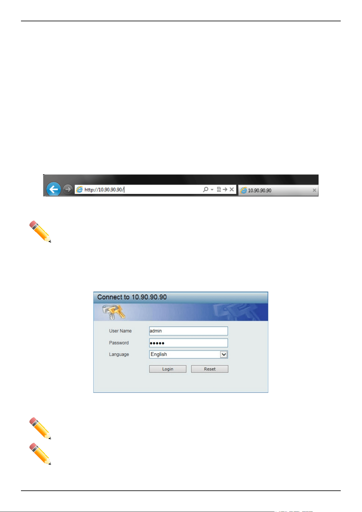
Logging into the Web UI
In the authentication window, enter the User Name and Password and click the Login button to access the Web UI.
Figure 2-2 Web UI Login Window
NOTE: For security reasons, it is highly recommended to configure a personal username and
password for this Switch.
NOTE: The Switch only supports ASCII characters for input values.
DGS-1520 Series Gigabit Ethernet Smart Managed Switch Web UI Reference Guide
3
Smart Wizard
After successfully connecting to the Web UI for the first time, the Smart Wizard embedded Web utility will be
launched. This wizard will guide the user through basic configuration steps that is essential for first time connection to
the Switch.
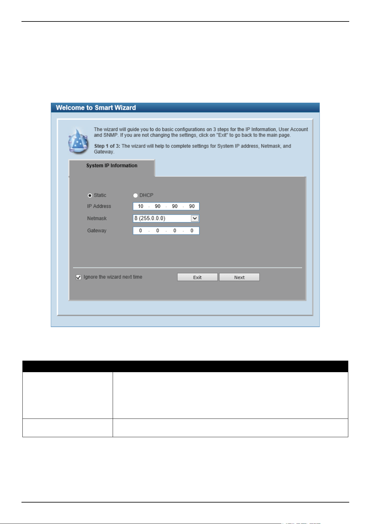
Step 1 - System IP Information
In this step, we can configure System IP Information.
Figure 2-3 System IP Information Window
The fields that can be configured are described below:
Parameter Description
Static
Select this option to manually assign and configure the IP address settings for the
Switch. After selecting this option, the following parameters can be configured:
• IP Address - Enter the IP address of the Switch here.
• Netmask - Select the Netmask option here.
• Gateway - Enter the IP address of the default gateway here.
DHCP
Select this option to obtain IP address settings automatically from a DHCP server
for the Switch.
Tick the Ignore the wizard next time option to skip the Smart Wizard on the next login.
Click the Exit button to discard the changes made, exit the Smart Wizard, and continue to the Web UI.
Click the Next button to accept the changes made and continue to the next step.
DGS-1520 Series Gigabit Ethernet Smart Managed Switch Web UI Reference Guide
4
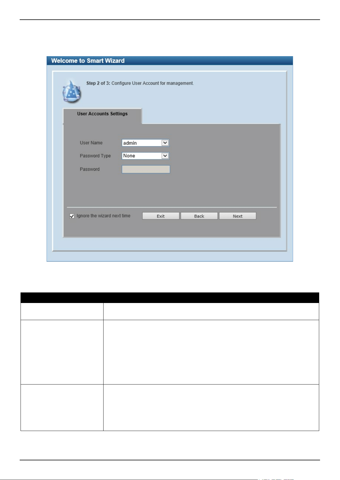
Step 2 - User Accounts Settings
In this step, we can configure the user account settings. This step can only be modified by a user account with the
privilege level of 15.
Figure 2-4 User Account Settings Window
The fields that can be configured are described below:
Parameter Description
User Name
Select the user name here. This is normally an administrator-level account with the
privilege level of 15.
Password Type
Select the password type here. Options to choose from are:
• None - Specifies that no password will be configured for this user account.
• Plain Text - Specifies that the password for this user account will be in the
plain text form.
• Encrypted-SHA1 - Specifies that the password for this user account will be
in the encrypted form using the SHA1 encryption method.
• Encrypted-MD5 - Specifies that the password for this user account will be
in the encrypted form using the MD5 encryption method.
Password
Enter the password for the user account either in the plain text format or the
encrypted format here based on the previous selection made.
In the encrypted format, the password will not be encrypted from plain text to the
encrypted format. Instead, the encrypted password must be entered.
To encrypt the password from plain text to the encrypted format, refer to the
Password Encryption window on page 36.
Tick the Ignore the wizard next time option to skip the Smart Wizard on the next login.
Click the Exit button to discard the changes made, exit the Smart Wizard, and continue to the Web UI.
DGS-1520 Series Gigabit Ethernet Smart Managed Switch Web UI Reference Guide
5
Click the Back button to discard the changes made and return to the previous step.
Click the Apply button to accept the changes made and continue to the Web UI.
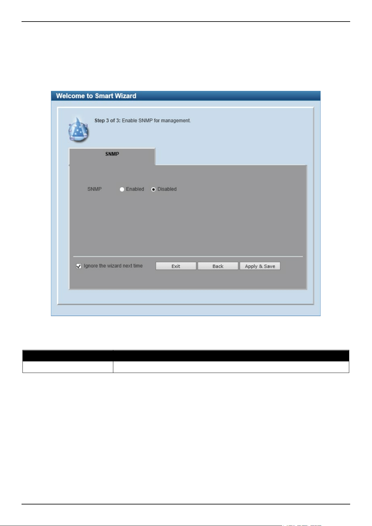
Step 3 - SNMP Settings
In this step, we can enable or disable the SNMP feature.
Figure 2-5 SNMP Window
The fields that can be configured are described below:
Parameter Description
SNMP
Select to enable or disable the SNMP feature here.
Tick the Ignore the wizard next time option to skip the Smart Wizard on the next login.
Click the Exit button to discard the changes made, exit the Smart Wizard, and continue to the Web UI.
Click the Back button to discard the changes made and return to the previous step.
Click the Apply & Save button to accept the changes made and continue to the Web UI.
DGS-1520 Series Gigabit Ethernet Smart Managed Switch Web UI Reference Guide
6
Web Interface Navigation
After accessing the Web UI, the following will be displayed:
Figure 2-6 Web User Interface Areas
Area Number Description
AREA 1
In this area, a graphical near real-time image of the front panel of the Switch is
displayed with ports and expansion modules. Some management functions like
port monitoring are also accessible here.
Click the D-Link logo to go to the D-Link website.
AREA 2 In this area, a toolbar with access to functions like Save, Tools, Online Help,
customized Language preferences, and a Logout option is available.
The user account and IP address, currently accessing the Web UI, is displayed on
the right in this toolbar.
AREA 3
In this area, the software features available in the Web UI are grouped into folders
containing hyperlinks that will open window frames in Area 4.
There is also a search option in this area that can be used to search for specific
feature keywords in the Web UI to easily find the link to the set of features.
AREA 4
In this area, configuration and monitoring window frames are available based on
the selections made in Area 3.
NOTE: The best screen resolution for viewing the Web UI is 1280 x 1024 pixels.
AREA 3
AREA 1
AREA 4
AREA 2
DGS-1520 Series Gigabit Ethernet Smart Managed Switch Web UI Reference Guide
7
3. System
Device Information
System Information Settings
Peripheral Settings
Port Configuration
Interface Description
Loopback Test
PoE
System Log
Time and SNTP
Time Range
Reset Button Settings
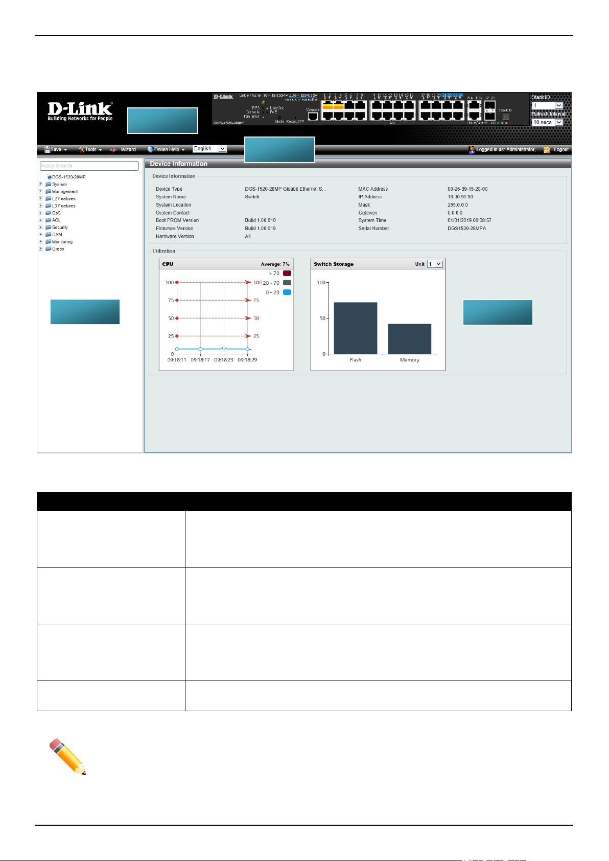
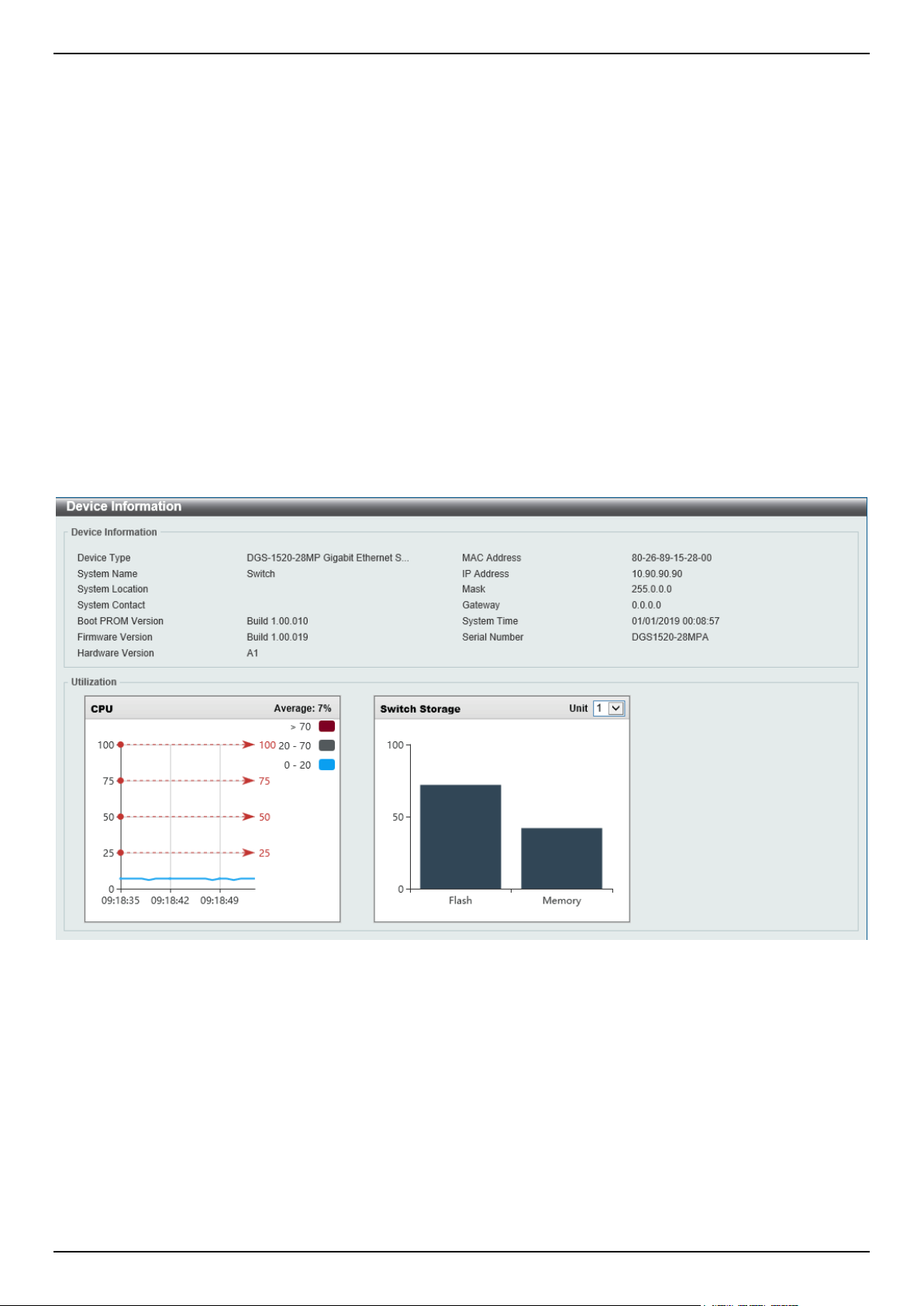
Device Information
In the Device Information section, the user can view a list of basic information regarding the Switch. It appears
automatically when you log on to the Switch. To return to the Device Information window after viewing other windows,
click the DGS-1520-28MP link.
Figure 3-1 Device Information Window
DGS-1520 Series Gigabit Ethernet Smart Managed Switch Web UI Reference Guide
8
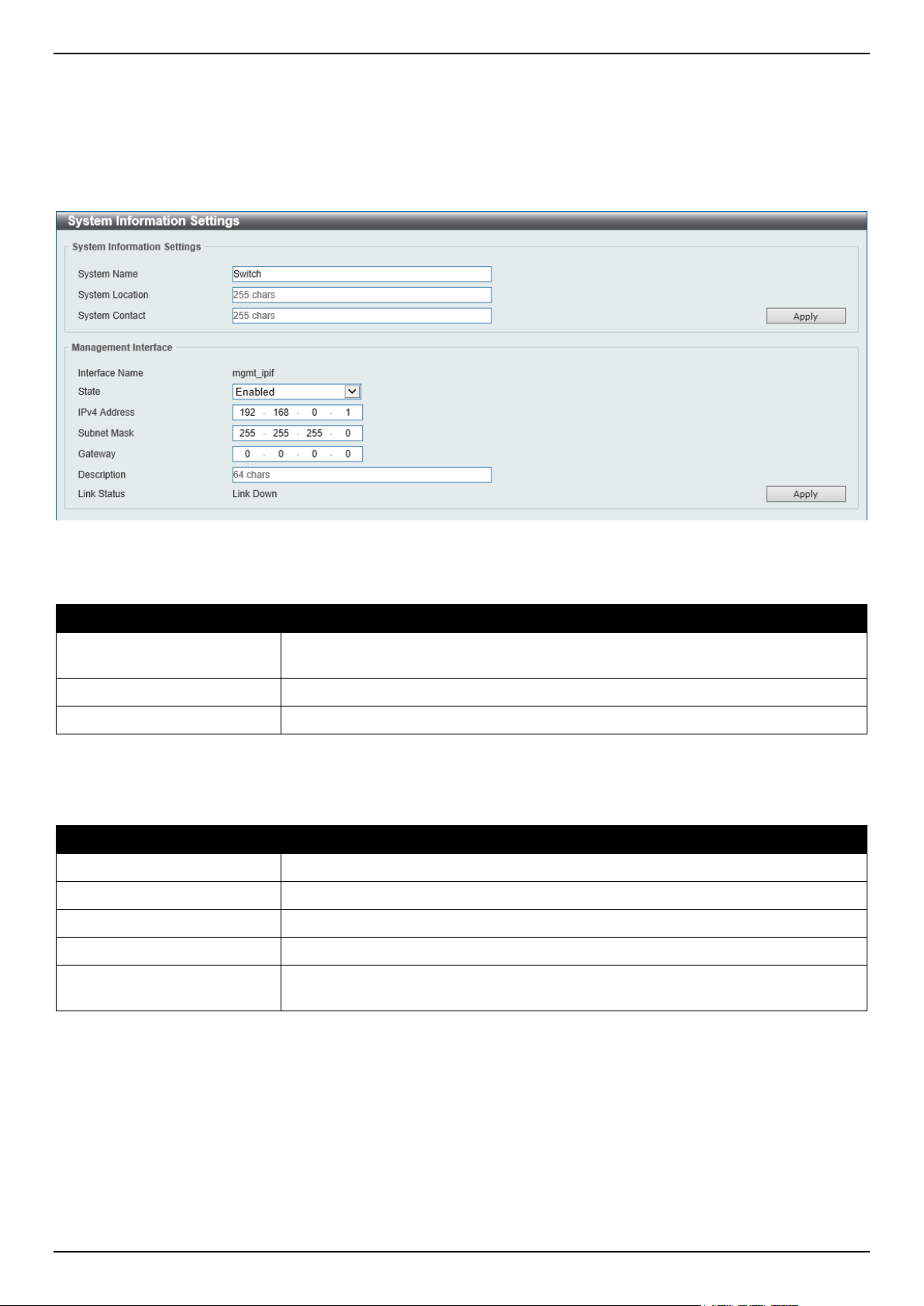
System Information Settings
This window is used to display and configure the system information settings and management interface configuration
settings. The Management Interface section is only available on the DGS-1520-28 and DGS-1520-52.
To view the following window, click System > System Information Settings, as shown below:
Figure 3-2 System Information Settings Window
The fields that can be configured in System Information Settings are described below:
Parameter Description
System Name
Enter a system name for the Switch, if so desired. This name will identify it in the
Switch network.
System Location
Enter the location of the Switch, if so desired.
System Contact
Enter a contact name for the Switch, if so desired.
Click the Apply button to accept the changes made.
The fields that can be configured in Management Interface are described below:
Parameter Description
State
Select to enable or disable the state of the management interface here.
IPv4 Address
Enter the IPv4 address for this interface here.
Subnet Mask
Enter the subnet mask for this interface here.
Gateway
Enter the gateway IPv4 address for this interface here.
Description
Enter the description for the management interface here. This can be up to 64
characters long.
Click the Apply button to accept the changes made.
DGS-1520 Series Gigabit Ethernet Smart Managed Switch Web UI Reference Guide
9
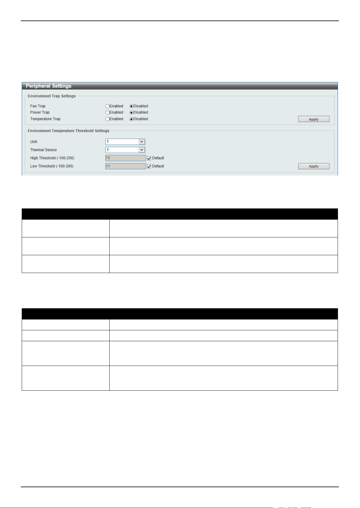
Peripheral Settings
This window is used to display and configure the environment trap settings and environment temperature threshold
settings.
To view the following window, click System > Peripheral Settings, as shown below:
Figure 3-3 Peripheral Settings Window
The fields that can be configured in Environment Trap Settings are described below:
Parameter Description
Fan Trap
Select to enable or disable the fan trap state for warning fan event (fan failed or fan
recover).
Power Trap
Select to enable or disable the power trap state for warning power event (power
failed or power recover).
Temperature Trap
Select to enable or disable the temperature trap state for warning temperature
event (temperature thresholds exceeded or temperature recover).
Click the Apply button to accept the changes made.
The fields that can be configured in Environment Temperature Threshold Settings are described below:
Parameter Description
Unit
Select the Switch unit that will be used for this configuration here.
Thermal
Select the thermal sensor ID.
High Threshold
Enter the high threshold value of the warning temperature setting. The range is
from -100 to 200 degrees Celsius. Tick the Default check box to return to the
default value.
Low Threshold
Enter the low threshold value of the warning temperature setting. The range is
from -100 to 200 degrees Celsius. Tick the Default check box to return to the
default value.
Click the Apply button to accept the changes made.
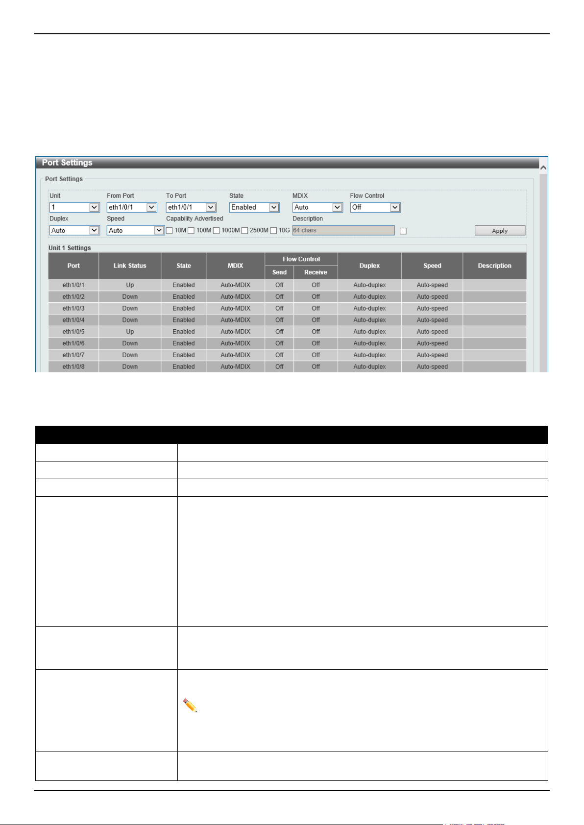
DGS-1520 Series Gigabit Ethernet Smart Managed Switch Web UI Reference Guide
10
Port Configuration
Port Settings
This window is used to display and configure the Switch's port settings.
To view the following window, click System > Port Configuration > Port Settings, as shown below:
Figure 3-4 Port Settings Window
The fields that can be configured are described below:
Parameter Description
Unit
Select the stacking unit ID of the Switch that will be configured here.
From Port - To Port
Select the appropriate port range used for the configuration here.
State
Select to enable or disable the physical port state here.
MDIX
Select the Medium Dependent Interface Crossover (MDIX) option here. Options to
choose from are:
• Auto - Select this option for auto-sensing of the optimal type of cabling.
• Normal - Select this option for normal cabling. If this option is selected, the
port is in the MDIX mode and can be connected to a PC NIC using a
straight-through cable or a port (in the MDI mode) on another Switch
through a crossover cable.
• Cross - Select this option for crossover cabling. If this option is selected, the
port is in the MDI mode and can be connected to a port (in the MDIX mode)
on another Switch through a straight cable.
Flow Control Select to turn flow control On or Off here. Ports configured for full-duplex use
802.3x flow control and Auto ports use an automatic selection of the two.
Note: This feature will not work through Switches that are physically stacked.
Duplex Select the duplex mode used here. Options to choose from are Auto, Half, and
Full.
NOTE: Due to hardware limitation, half-duplex operation is not supported on
the 2.5 Gbps ports when the speed is operating at 100 Mbps. Only full-duplex
operation is supported. For 100 Mbps half-duplex operation, connect to any of
the 1 Gbps ports.
Speed
Select the port speed option here. This option will manually force the connection
speed on the selected port to connect at the specified speed only.

DGS-1520 Series Gigabit Ethernet Smart Managed Switch Web UI Reference Guide
11
Parameter Description
The Master setting will allow the port to advertise capabilities related to duplex,
speed, and physical layer type. The master setting will also determine the master
and slave relationship between the two connected physical layers. This
relationship is necessary for establishing the timing control between the two
physical layers. The timing control is set on a master physical layer by a local
source.
The Slave setting uses loop timing, where the timing comes from a data stream
received from the master. If one connection is set for master, the other side of the
connection must be set for slave. Any other configuration will result in a 'link down'
status for both ports.
Options to choose from are:
• Auto - Specifies that for copper ports, auto-negotiation will start to negotiate
the speed and flow control with its link partner. For fiber ports, auto-
negotiation will start to negotiate the clock and flow control with its link
partner.
• 10M - Specifies to force the port speed to 10 Mbps. This option is only
available for 10 Mbps copper connections.
• 100M - Specifies to force the port speed to 100 Mbps. This option is only
available for 100 Mbps copper connections.
• 1000M - Specifies to force the port speed to 1 Gbps.
• 1000M Master - Specifies to force the port speed to 1 Gbps and operates
as the master, to facilitate the timing of transmit and receive operations.
• 1000M Slave - Specifies to force the port speed to 1 Gbps and operates as
the slave, to facilitate the timing of transmit and receive operations.
• 2500M - Specifies to force the port speed to 2.5 Gbps.
• 2500M Master - Specifies to force the port speed to 2.5 Gbps and operates
as the master, to facilitate the timing of transmit and receive operations.
• 2500M Slave - Specifies to force the port speed to 2.5 Gbps and operates
as the slave, to facilitate the timing of transmit and receive operations.
• 10G - Specifies to force the port speed to 10 Gbps.
• 10G Master - Specifies to force the port speed to 10 Gbps and operates as
the master, to facilitate the timing of transmit and receive operations.
• 10G Slave - Specifies to force the port speed to 10 Gbps and operates as
the slave, to facilitate the timing of transmit and receive operations.
Capability Advertised When the Speed is set to Auto, these capabilities are advertised during auto-
negotiation.
Description
Select the checkbox and enter the description for the corresponding port here. This
can be up to 64 characters long.
Click the Apply button to accept the changes made.
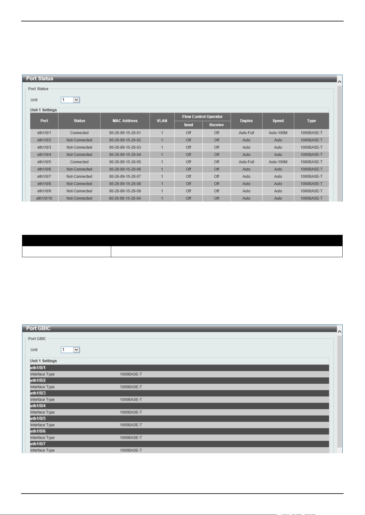
DGS-1520 Series Gigabit Ethernet Smart Managed Switch Web UI Reference Guide
12
Port Status
This window is used to view the Switch's physical port status and settings.
To view the following window, click System > Port Configuration > Port Status, as shown below:
Figure 3-5 Port Status Window
The fields that can be configured are described below:
Parameter Description
Unit
Select the stacking unit ID of the Switch that will be displayed here.
Port GBIC
This window is used to view active GBIC information found on each applicable physical port of this Switch.
To view the following window, click System > Port Configuration > Port GBIC, as shown below:
Figure 3-6 Port GBIC Window
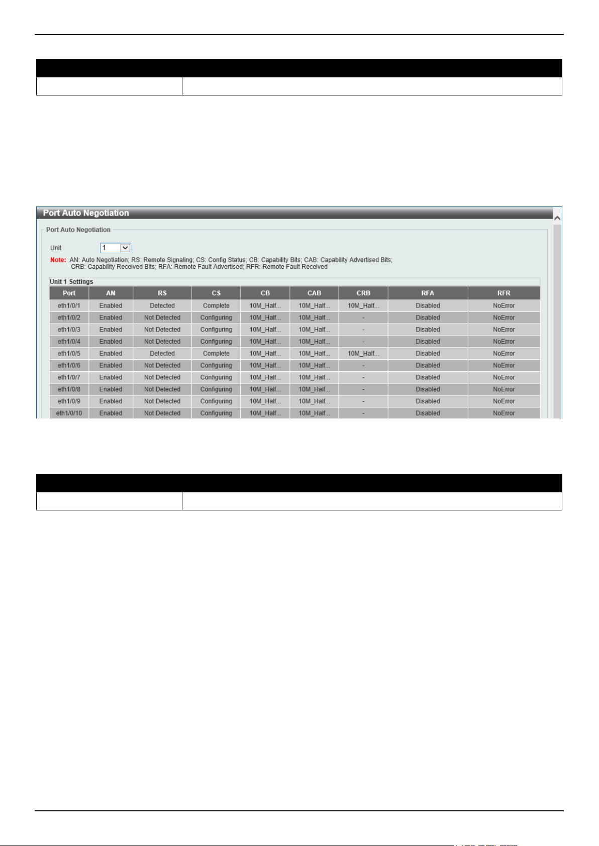
DGS-1520 Series Gigabit Ethernet Smart Managed Switch Web UI Reference Guide
13
The fields that can be configured are described below:
Parameter Description
Unit
Select the Switch unit that will be used for this display here.
Port Auto Negotiation
This window is used to view detailed port auto-negotiation information.
To view the following window, click System > Port Configuration > Port Auto Negotiation, as shown below:
Figure 3-7 Port Auto Negotiation Window
The fields that can be configured are described below:
Parameter Description
Unit
Select the stacking unit ID of the Switch that will be displayed here.
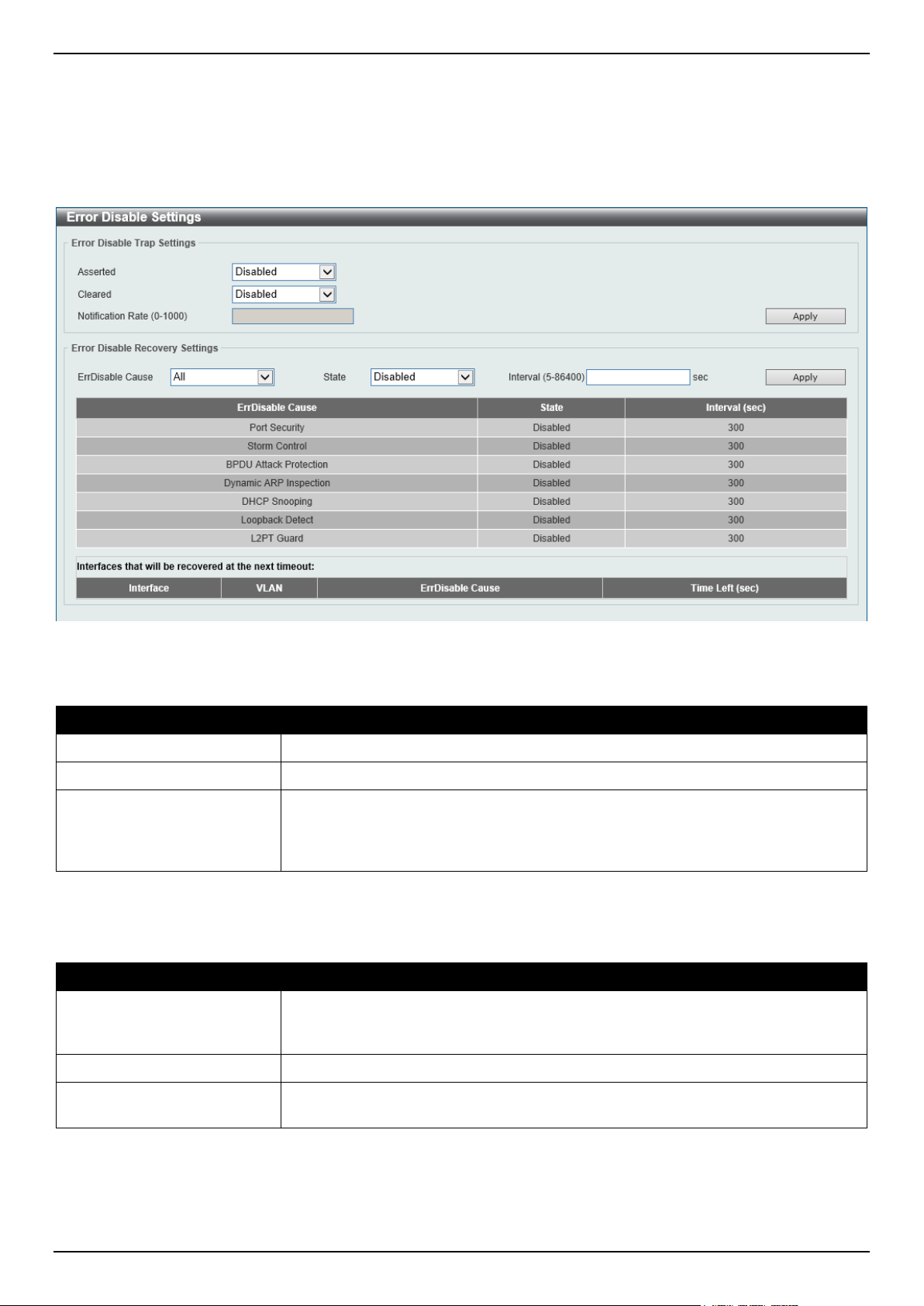
DGS-1520 Series Gigabit Ethernet Smart Managed Switch Web UI Reference Guide
14
Error Disable Settings
This window is used to display and configure the recovery from the Error Disable causes and to configure the recovery
interval.
To view the following window, click System > Port Configuration > Error Disable Settings, as shown below:
Figure 3-8 Error Disable Settings Window
The fields that can be configured for Error Disable Trap Settings are described below:
Parameter Description
Asserted
Specifies to enable or disable notifications for entering into the error-disabled state.
Cleared
Specifies to enable or disable notifications for exiting from the error-disabled state.
Notification Rate
Enter the notification rate value here. This sets the number of traps per minute.
The packets that exceed the rate will be dropped. The range is from 0 to 1000. The
default value (0) indicates that an SNMP trap will be generated for every change of
the error disabled state.
Click the Apply button to accept the changes made.
The fields that can be configured for Error Disable Recovery Settings are described below:
Parameter Description
ErrDisable Cause Select the error disabled cause here. Options to choose from are Port Security,
Storm Control, BPDU Attack Protection, Dynamic ARP Inspection, DHCP
Snooping, Loopback Detect, and L2PT Guard.
State
Select to enable or disable the error disabled recovery feature here.
Interval
Enter the time, in seconds, to recover the port from the error state caused by the
specified module. The range is from 5 to 86400.
Click the Apply button to accept the changes made.
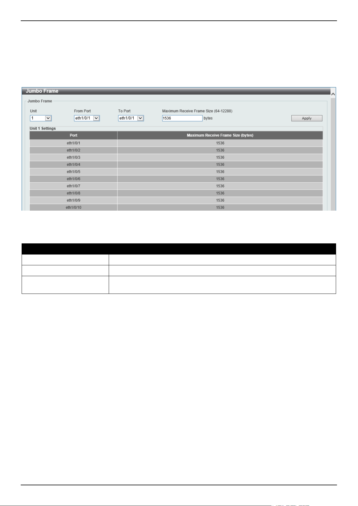
DGS-1520 Series Gigabit Ethernet Smart Managed Switch Web UI Reference Guide
15
Jumbo Frame
This window is used to display and configure the jumbo frame size and settings. The Switch supports jumbo frames.
Jumbo frames are Ethernet frames with more than 1,518 bytes of payload. The Switch supports jumbo frames with a
maximum frame size of up to 12,288 bytes.
To view the following window, click System > Port Configuration > Jumbo Frame, as shown below:
Figure 3-9 Jumbo Frame Window
The fields that can be configured are described below:
Parameter Description
Unit
Select the stacking unit ID of the Switch that will be configured here.
From Port - To Port
Select the appropriate port range used for the configuration here.
Maximum Receive Frame
Size
Enter the maximum receive frame size value here. This value must be between 64
and 12288 bytes. By default, this value is 1536 bytes.
Click the Apply button to accept the changes made.
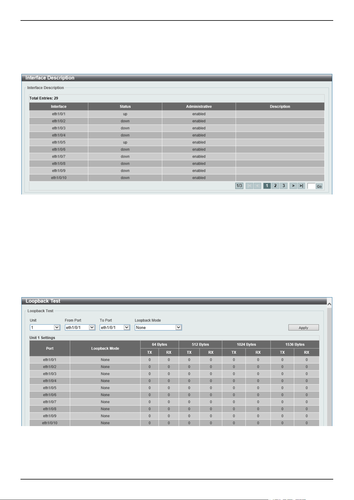
DGS-1520 Series Gigabit Ethernet Smart Managed Switch Web UI Reference Guide
16
Interface Description
This window is used to display the status, administrative status, and description of each port on the Switch.
To view the following window, click System > Interface Description, as shown below:
Figure 3-10 Interface Description Window
Enter a page number and click the Go button to navigate to a specific page when multiple pages exist.
Loopback Test
This window is used to display and configure the loopback settings of the physical port interfaces and to perform
loopback tests.
To view the following window, click System > Loopback Test, as shown below:
Figure 3-11 Loopback Settings Window

DGS-1520 Series Gigabit Ethernet Smart Managed Switch Web UI Reference Guide
17
The fields that can be configured are described below:
Parameter Description
Unit
Select the Switch unit that will be used for this configuration here.
From Port - To Port
Select the appropriate port range used for the configuration here.
Loopback Mode
Select the loopback mode here. Options to choose from are:
• None - Specifies not to enable the loopback mode.
• Internal MAC - Specifies the internal loopback mode at the MAC layer.
• Internal PHY Default - Specifies the internal loopback mode at the PHY
layer to test the default medium.
• Internal PHY Copper - Specifies the internal loopback mode at the PHY
layer to test the copper medium.
• Internal PHY Fiber - Specifies the internal loopback mode at the PHY layer
to test the fiber medium.
• External MAC - Specifies the external loopback mode at the MAC layer.
• External PHY Default - Specifies the external loopback mode at the PHY
layer to test the default medium.
• External PHY Copper - Specifies the external loopback mode at the PHY
layer to test the copper medium.
• External PHY Fiber - Specifies the external loopback mode at the PHY
layer to test the fiber medium.
Click the Apply button to accept the changes made.
PoE
The DGS-1520-28MP and DGS-1520-52MP switches support Power over Ethernet (PoE) as defined by the IEEE
802.3af and 802.3at. All ports can support PoE up to 30W. The Switch ports can supply about 48 VDC power to
Powered Devices (PDs) over Category 5 or Category 3 UTP Ethernet cables. The Switch follows the standard Power
Sourcing Equipment (PSE) pin-out Alternative A, whereby power is sent out over pins 1, 2, 3, and 6. The Switches
work with all D-Link 802.3af capable devices.
The Switch includes the following PoE features:
• Auto-discovery recognizes the connection of a PD and automatically sends power to it.
• The auto-disable feature occurs under two conditions:
o If the total power consumption exceeds the system power limit
o If the per-port power consumption exceeds the per port power limit
• Active circuit protection automatically disables the port if there is a short. Other ports will remain active.
Based on IEEE 802.3af/at, power is received and supplied according to the following classifications:
Class Maximum power used by the PD Maximum power supplied by the Switch
0
12.95 Watts 15.4 Watts
1
3.84 Watts 4 Watts
2
6.49 Watts 7 Watts
3
12.95 Watts 15.4 Watts
4
25.5 Watts 30 Watts
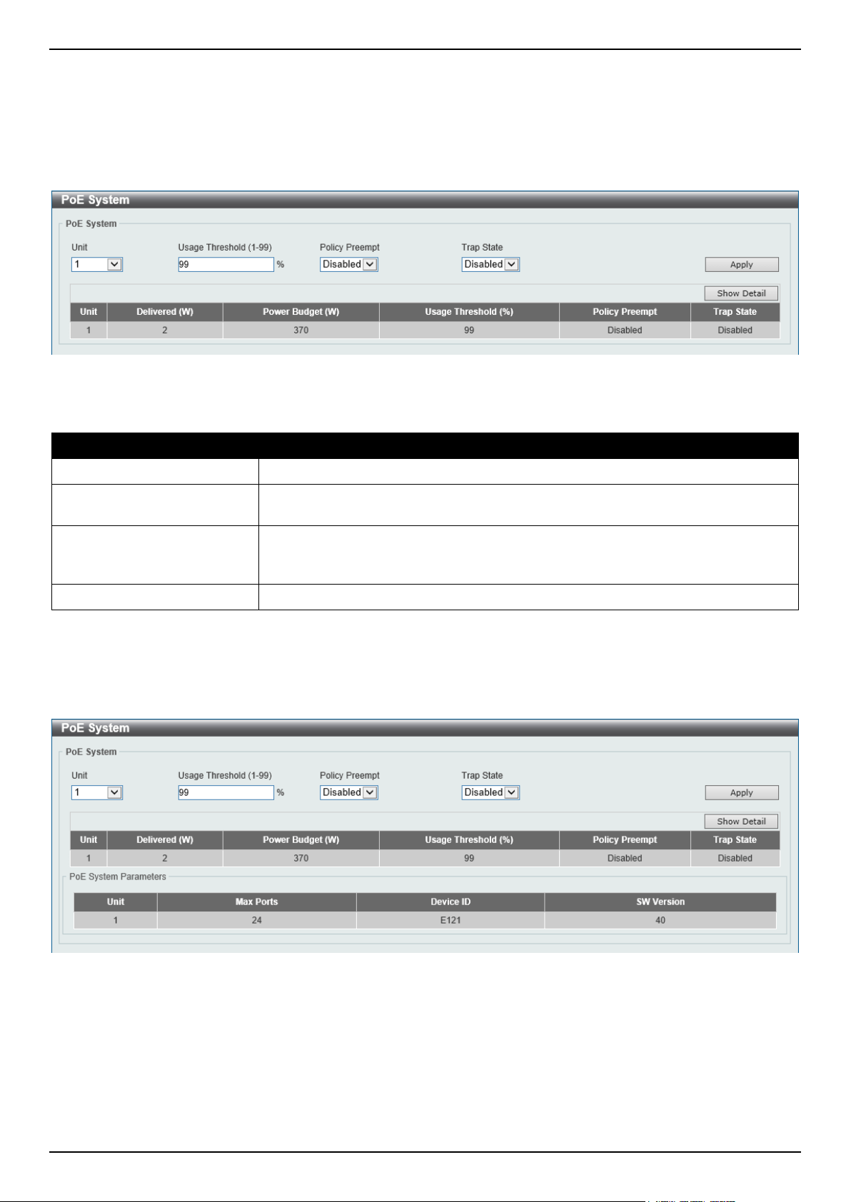
DGS-1520 Series Gigabit Ethernet Smart Managed Switch Web UI Reference Guide
18
PoE System
This window is used to configure the PoE system and display the detailed power information and PoE chip parameters
for PoE modules.
To view the following window, click System > PoE > PoE System, as shown below:
Figure 3-12 PoE System Window
The fields that can be configured for PoE System are described below:
Parameter Description
Unit
Select the stacking unit ID of the Switch that will be configured here.
Usage Threshold
Enter the usage threshold to generate a log and send the corresponding standard
notification. The range is from 1 to 99 percent.
Policy Preempt
Select this option to enable or disable the disconnection of the Powered Device
(PD), which is power-provisioned with a lower priority in order to release the power
to the new connected PD with higher priority under power shortage conditions.
Trap State
Select this option to enable or disable the sending of PoE trap notifications.
Click the Apply button to accept the changes made.
Click the Show Detail button to see the PoE system Parameters table at the bottom of the window.
After clicking the Show Detail button, the following window will appear.
Figure 3-13 PoE System (Show Detail) Window
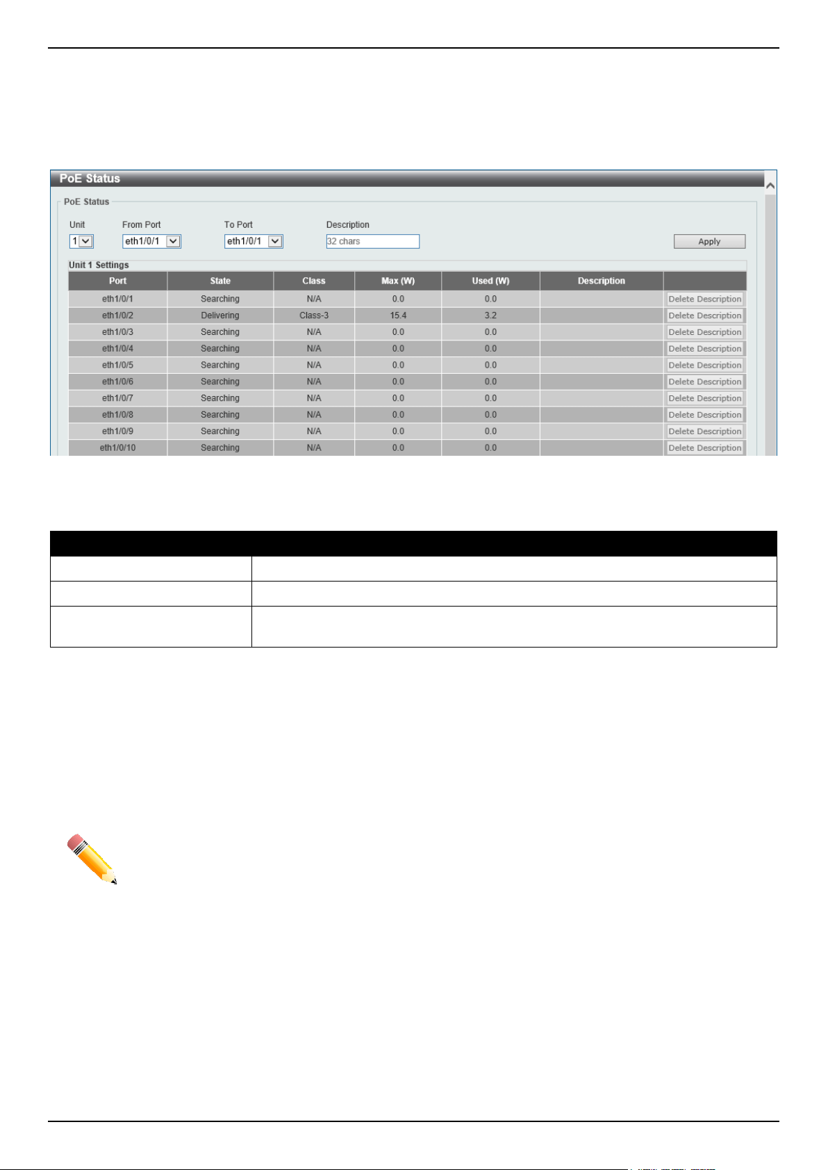
DGS-1520 Series Gigabit Ethernet Smart Managed Switch Web UI Reference Guide
19
PoE Status
This window is used to configure the description and display the PoE status of each port.
To view the following window, click System > PoE > PoE Status, as shown below:
Figure 3-14 PoE Status Window
The fields that can be configured for PoE Status are described below:
Parameter Description
Unit
Select the stacking unit ID of the Switch that will be configured here.
From Port - To Port
Select the appropriate port range used for the configuration here.
Description
Enter the text that describes the PD connected to a PoE interface. The maximum
length is 32 characters.
Click the Apply button to accept the changes made.
Click the Delete Description button to remove the description from the entry.
PoE Configuration
This window is used to display and configure the PoE configuration settings.
NOTE: If the Switch failed to supply power to the IEEE 802.3at Powered Device (PD),
• Check if the PD connected to the port supports the IEEE 802.3at standard
• Manually configure the PoE power limit value to 30 Watts for the corresponding port
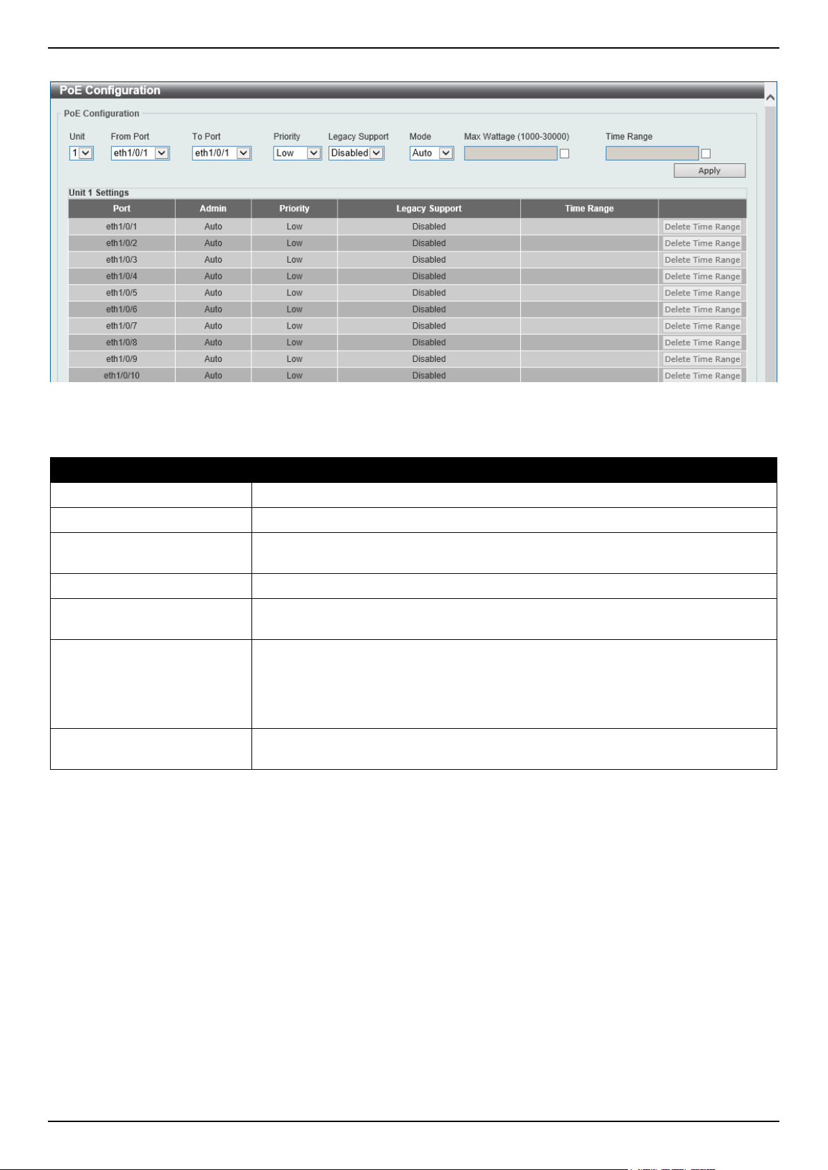
DGS-1520 Series Gigabit Ethernet Smart Managed Switch Web UI Reference Guide
20
To view the following window, click System > PoE > PoE Configuration, as shown below:
Figure 3-15 PoE Configuration Window
The fields that can be configured for PoE Configuration are described below:
Parameter Description
Unit
Select the stacking unit ID of the Switch that will be configured here.
From Port - To Port
Select the appropriate port range used for the configuration here.
Priority
Select the priority for provisioning power to the port. Options to choose from are
Critical, High and Low.
Legacy Support
Select this option to enable or disable the support of legacy PD.
Mode
Select the power management mode for the PoE ports. Options to choose from
are Auto and Never.
Max Wattage When selecting Auto in the Mode drop-down list, this option appears. Tick the
check box and enter the maximum wattage of power that can be provisioned to the
auto-detected PD. If the value is not entered, the class of the PD automatically
determines the maximum wattage, which can be provisioned. The range for
maximum wattage is between 1000 mW and 30000 mW.
Time Range When selecting Auto in the Mode drop-down list, this option appears. Tick the
check box and enter the name of the time range to determine the activation period.
Click the Apply button to accept the changes made.
Click the Delete Time Range button remove the time range association for the entry.
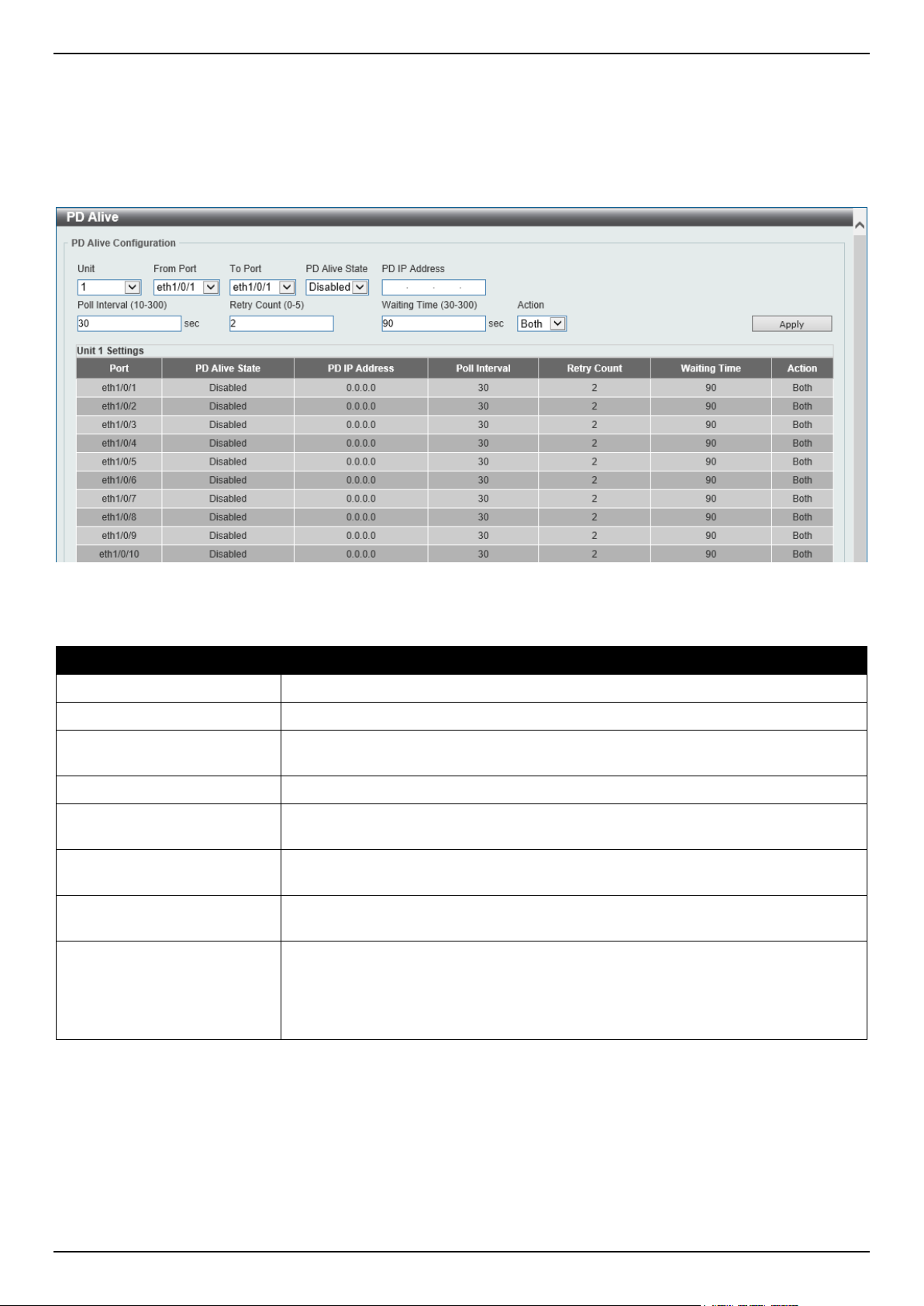
DGS-1520 Series Gigabit Ethernet Smart Managed Switch Web UI Reference Guide
21
PD Alive
This window is used to display and configure the PoE PD alive settings. The PoE alive feature provides the solution
when PD devices stop working or are not responding using the ping mechanism.
To view the following window, click System > PoE > PD Alive, as shown below:
Figure 3-16 PD Alive Window
The fields that can be configured for PD Alive Configuration are described below:
Parameter Description
Unit
Select the stacking unit ID of the Switch that will be configured here.
From Port - To Port
Select the appropriate port range used for the configuration here.
PD Alive State
Select to enable or disable the state of the PoE alive function on the specified
port(s) here.
PD IP Address
Enter the IPv4 address of the target PD here.
Poll Interval
Enter the poll interval value here. The range is from 10 to 300 seconds. This is the
interval at which ping requests will be sent to the target PD to check the status.
Retry Count
Enter the retry count value here. The range is from 0 to 5. This is the amount of
times that the ping request will be resend if the target PD does not respond.
Waiting Time
Enter the waiting time value here. The range is from 30 to 300 seconds. This is the
time the Switch will wait for the PD to recover from rebooting.
Action
Select the action that will be taken here. Options to choose from are:
• Reset - Specifies to reset the PoE port state.
• Notify - Specifies to send logs and traps to notify the administrator.
• Both - Specifies to send logs and traps and then to reset the PoE port state.
Click the Apply button to accept the changes made.
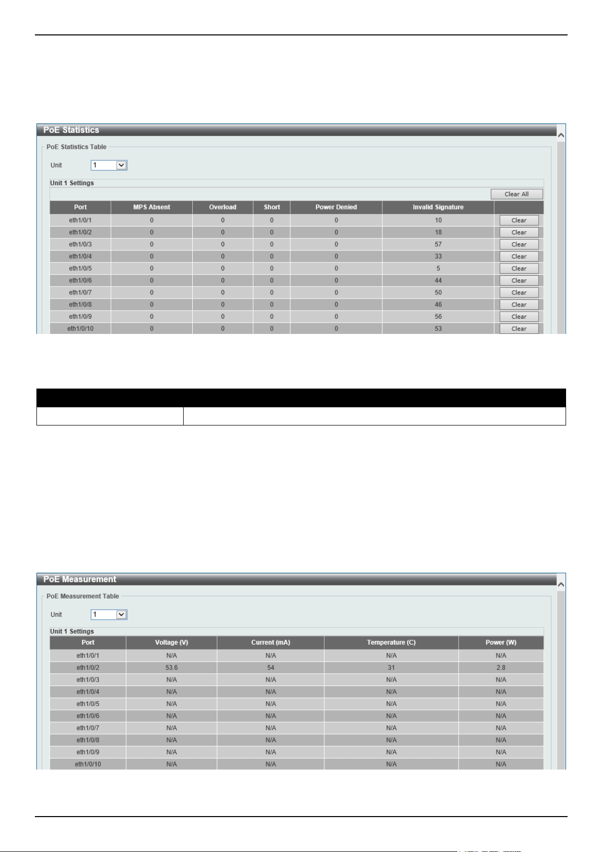
DGS-1520 Series Gigabit Ethernet Smart Managed Switch Web UI Reference Guide
22
PoE Statistics
This window is used to display and clear the PoE statistics on the Switch ports.
To view the following window, click System > PoE > PoE Statistics, as shown below:
Figure 3-17 PoE Statistics Window
The fields that can be configured for PoE Statistics Table are described below:
Parameter Description
Unit
Select the stacking unit ID of the Switch that will be used here.
Click the Clear All button to clear PoE statistics for all ports.
Click the Clear button to clear the PoE statistics for the corresponding port.
PoE Measurement
This window is used to display the PoE measurement information on the Switch ports.
To view the following window, click System > PoE > PoE Measurement, as shown below:
Figure 3-18 PoE Measurement Window
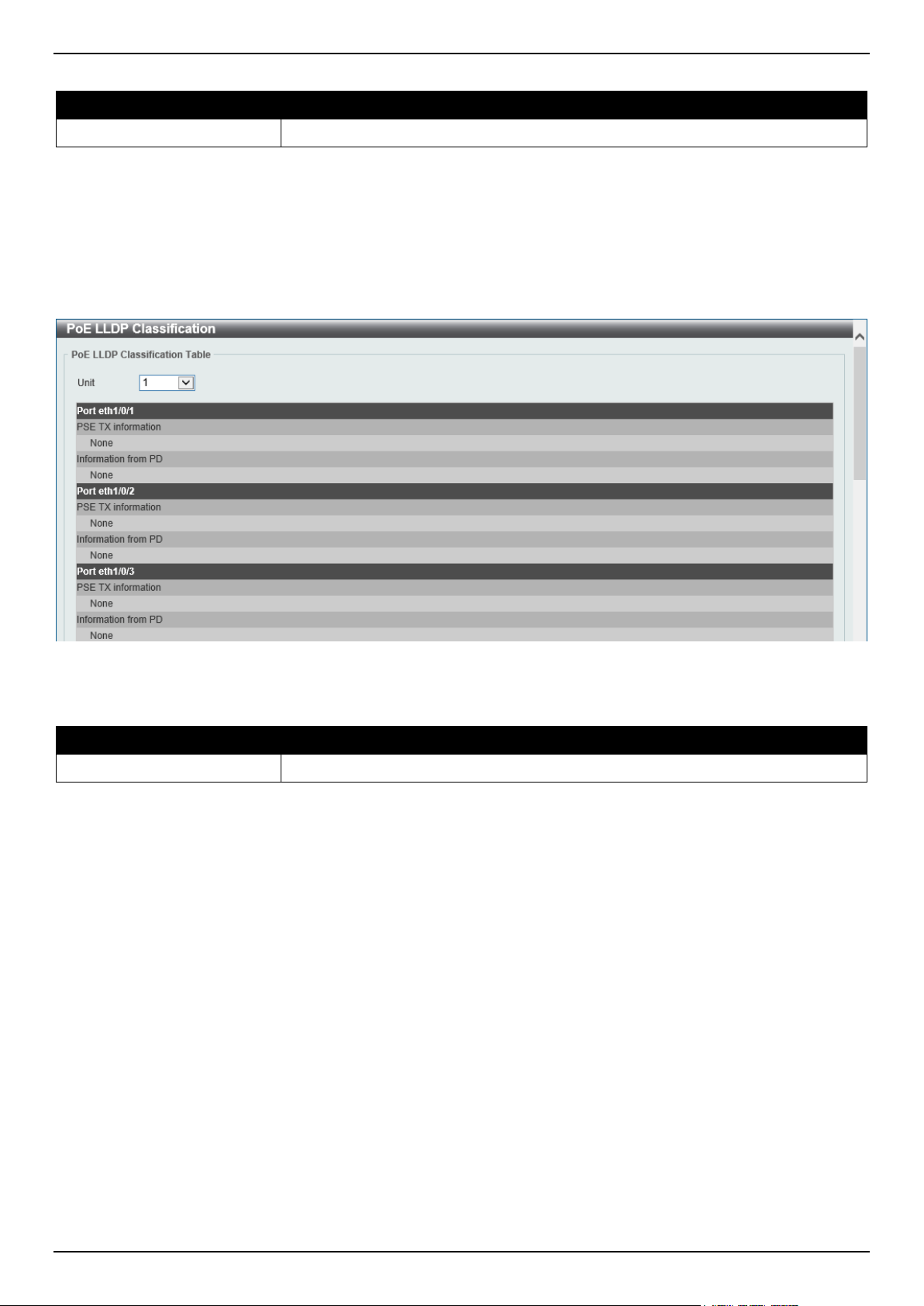
DGS-1520 Series Gigabit Ethernet Smart Managed Switch Web UI Reference Guide
23
The fields that can be configured for PoE Measurement Table are described below:
Parameter Description
Unit
Select the stacking unit ID of the Switch that will be used here.
PoE LLDP Classification
This window is used to display the PoE Link Layer Discovery Protocol (LLDP) classification.
To view the following window, click System > PoE > PoE LLDP Classification, as shown below:
Figure 3-19 PoE LLDP Classification Window
The fields that can be configured for PoE LLDP Classification Table are described below:
Parameter Description
Unit
Select the stacking unit ID of the Switch that will be used here.
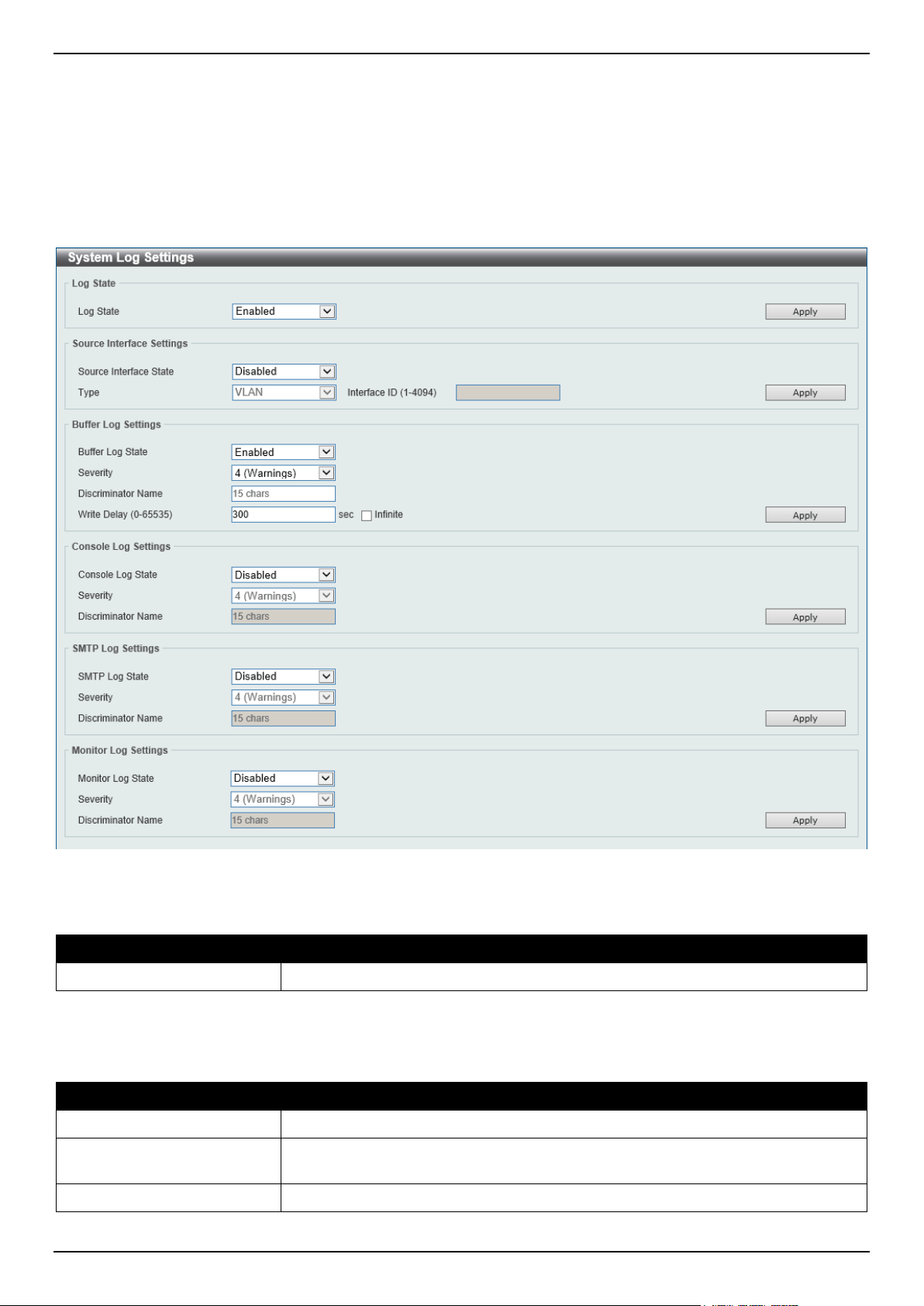
DGS-1520 Series Gigabit Ethernet Smart Managed Switch Web UI Reference Guide
24
System Log
System Log Settings
This window is used to display and configure the system log settings.
To view the following window, click System > System Log > System Log Settings, as shown below:
Figure 3-20 System Log Settings Window
The fields that can be configured for Log State are described below:
Parameter Description
Log State
Select the enable or disable the global system log state here.
Click the Apply button to accept the changes made.
The fields that can be configured for Source Interface Settings are described below:
Parameter Description
Source Interface State
Select this option to enable or disable the global source interface state.
Type
Select the type of interface that will be used. Options to choose from are
Loopback, Mgmt, and VLAN.
Interface ID
Enter the interface ID used here.

DGS-1520 Series Gigabit Ethernet Smart Managed Switch Web UI Reference Guide
25
Parameter Description
For loopback interfaces, this ID can be from 1 to 8. For the management (Mgmt)
interface this value is always 0.
For VLAN interfaces, this value is from 1 to 4094.
Click the Apply button to accept the changes made.
The fields that can be configured for Buffer Log Settings are described below:
Parameter Description
Buffer Log State
Select to globally enable or disable the buffer log state here. Options to choose
from are Enable, Disabled, and Default. When selecting the Default option, the
global buffer log state will follow the default behavior.
Severity
Select the severity value of the type of information that will be logged. Options to
choose from are 0 (Emergencies), 1 (Alerts), 2 (Critical), 3 (Errors), 4
(Warnings), 5 (Notifications), 6 (Informational), and 7 (Debugging).
Discriminator Name
Enter the discriminator name used here. This name can be up to 15 characters
long. This specifies the name of the discriminator profile that will be used to filter
buffer log messages based on the filtering criteria specified within that profile.
Write Delay
Enter the log write delay value here. This value must be between 0 and 65535
seconds. By default, this value is 300 seconds. Tick the Infinite option, to disable
the write delay feature.
Click the Apply button to accept the changes made.
The fields that can be configured for Console Log Settings are described below:
Parameter Description
Console Log State
Select to globally enable or disable the console log state here.
Severity
Select the severity value of the type of information that will be logged. Options to
choose from are 0 (Emergencies), 1 (Alerts), 2 (Critical), 3 (Errors), 4
(Warnings), 5 (Notifications), 6 (Informational), and 7 (Debugging).
Discriminator Name
Enter the discriminator name used here. This name can be up to 15 characters
long. This specifies the name of the discriminator profile that will be used to filter
console log messages based on the filtering criteria specified within that profile.
Click the Apply button to accept the changes made.
The fields that can be configured for SMTP Log Settings are described below:
Parameter Description
SMTP Log State
Select to globally enable or disable the SMTP log state here.
Severity
Select the severity value of the type of information that will be logged. Options to
choose from are 0 (Emergencies), 1 (Alerts), 2 (Critical), 3 (Errors), 4
(Warnings), 5 (Notifications), 6 (Informational), and 7 (Debugging).
Discriminator Name
Enter the discriminator name used here. This name can be up to 15 characters
long. This specifies the name of the discriminator profile that will be used to filter
SMTP log messages based on the filtering criteria specified within that profile.
Click the Apply button to accept the changes made.
The fields that can be configured for Monitor Log Settings are described below:
Parameter Description
Monitor Log State
Select to globally enable or disable the monitor log state here.
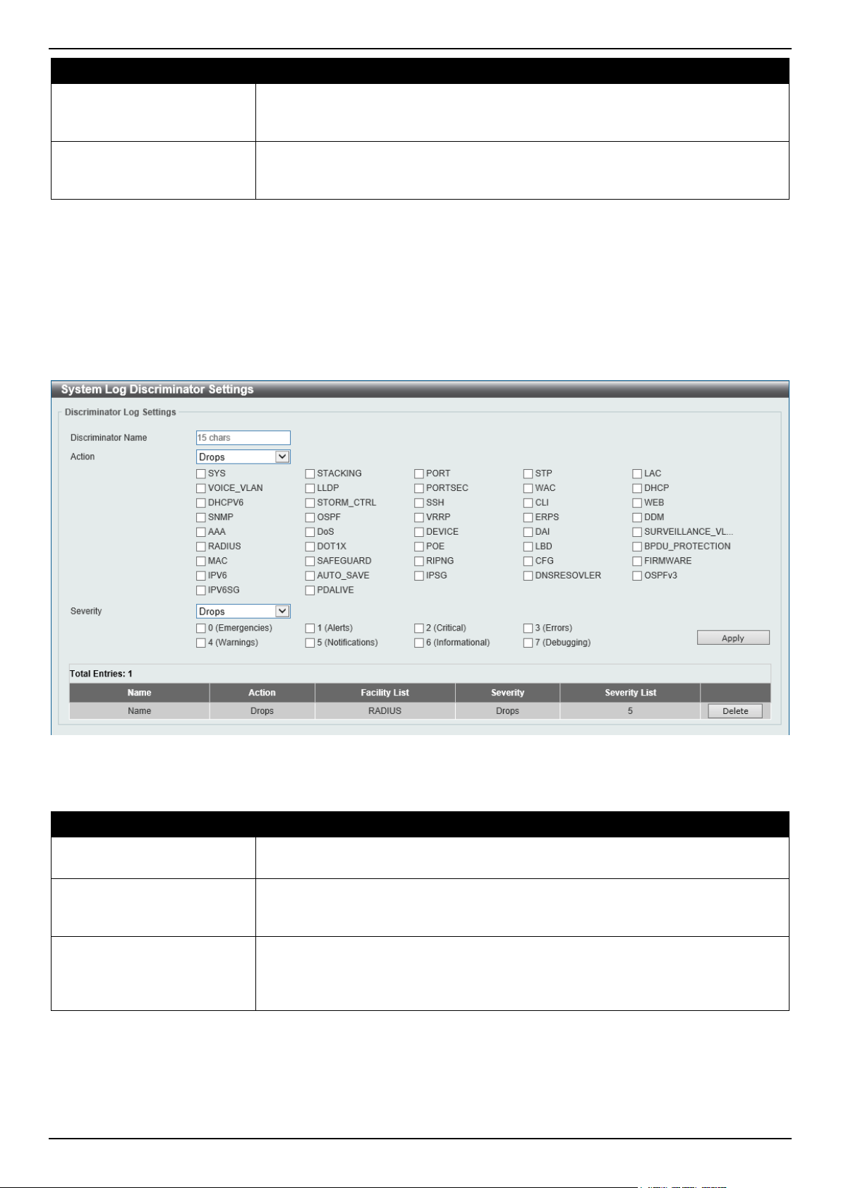
DGS-1520 Series Gigabit Ethernet Smart Managed Switch Web UI Reference Guide
26
Parameter Description
Severity
Select the severity value of the type of information that will be logged. Options to
choose from are 0 (Emergencies), 1 (Alerts), 2 (Critical), 3 (Errors), 4
(Warnings), 5 (Notifications), 6 (Informational), and 7 (Debugging).
Discriminator Name
Enter the discriminator name used here. This name can be up to 15 characters
long. This specifies the name of the discriminator profile that will be used to filter
monitor log messages based on the filtering criteria specified within that profile.
Click the Apply button to accept the changes made.
System Log Discriminator Settings
This window is used to display and configure the system log discriminator settings.
To view the following window, click System > System Log > System Log Discriminator Settings, as shown below:
Figure 3-21 System Log Discriminator Settings Window
The fields that can be configured are described below:
Parameter Description
Discriminator Name
Enter the name of the discriminator profile here. This name can be up to 15
characters long.
Action
Select the facility behavior option and the type of facility that will be associated with
the selected behavior here. Behavior options to choose from are Drops and
Includes.
Severity
Select the severity behavior option and the value of the type of information that will
be logged. Behavior options to choose from are Drops and Includes. Severity
value options to choose from are 0 (Emergencies), 1 (Alerts), 2 (Critical), 3
(Errors), 4 (Warnings), 5 (Notifications), 6 (Informational), and 7 (Debugging).
Click the Apply button to accept the changes made.
Click the Delete button to delete the specified entry.
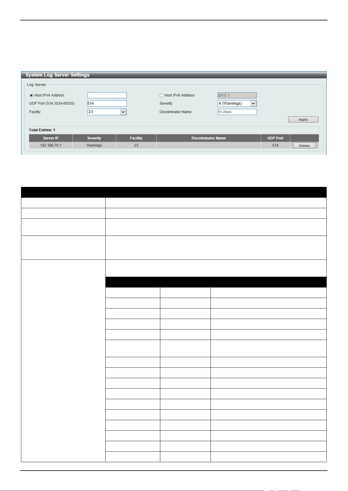
DGS-1520 Series Gigabit Ethernet Smart Managed Switch Web UI Reference Guide
27
System Log Server Settings
This window is used to display and configure the system log server settings.
To view the following window, click System > System Log > System Log Server Settings, as shown below:
Figure 3-22 System Log Server Settings Window
The fields that can be configured are described below:
Parameter Description
Host IPv4 Address
Enter the system log server IPv4 address here.
Host IPv6 Address
Enter the system log server IPv6 address here.
UDP Port
Enter the system log server UDP port number here. This value must be either 514
or between 1024 and 65535. By default, this value is 514.
Severity
Select the severity value of the type of information that will be logged. Options to
choose from are 0 (Emergencies), 1 (Alerts), 2 (Critical), 3 (Errors), 4
(Warnings), 5 (Notifications), 6 (Informational), and 7 (Debugging).
Facility Select the facility number that will be logged here. The range is from 0 to 23. Each
facility number is associated with a specific facility. See the table below:
Number Name Description
0
kern Kernel messages
1
user User-level messages
2
mail Mail system
3
daemon System daemons
4
auth1 Security/authorization messages
5
syslog Messages generated internally by the
SYSLOG
6
lpr Line printer sub-system
7
news Network news sub-system
8
uucp UUCP sub-system
9
clock1 Clock daemon
10
auth2 Security/authorization messages
11
ftp FTP daemon
12
ntp NTP subsystem
13
logaudit Log audit
14
logalert Log alert
15
clock2 Clock daemon
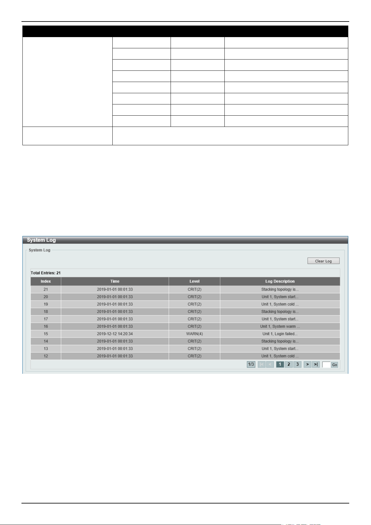
DGS-1520 Series Gigabit Ethernet Smart Managed Switch Web UI Reference Guide
28
Parameter Description
16
local0 Local use 0 (local0)
17
local1 Local use 1 (local1)
18
local2 Local use 2 (local2)
19
local3 Local use 3 (local3)
20
local4 Local use 4 (local4)
21
local5 Local use 5 (local5)
22
local6 Local use 6 (local6)
23
local7 Local use 7 (local7)
Discriminator Name
Enter the name of the discriminator that will be used to filter messages sent to the
log server here. This name can be up to 15 characters long.
Click the Apply button to accept the changes made.
Click the Delete button to delete the specified entry.
System Log
This window is used to view and clear the system log.
To view the following window, click System > System Log > System Log, as shown below:
Figure 3-23 System Log Window
Click the Clear Log button to clear the system log entries displayed in the table.
Enter a page number and click the Go button to navigate to a specific page when multiple pages exist.
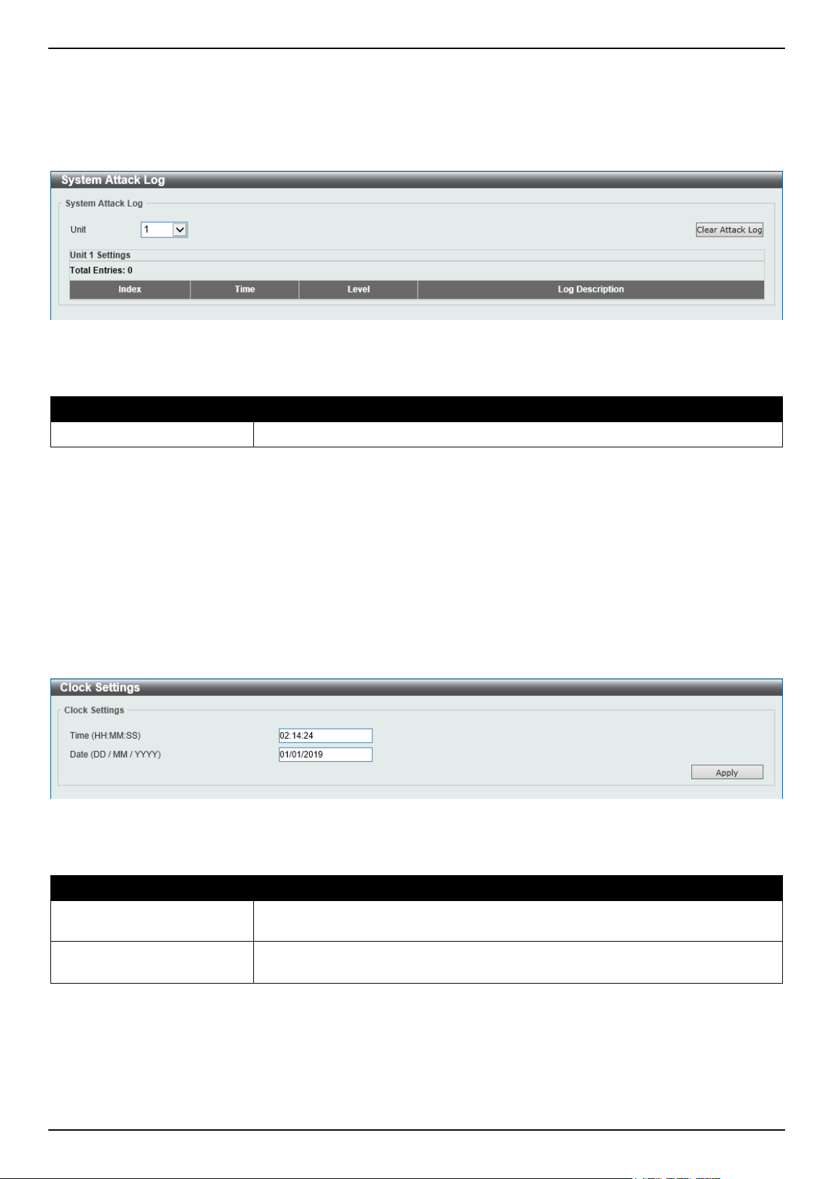
DGS-1520 Series Gigabit Ethernet Smart Managed Switch Web UI Reference Guide
29
System Attack Log
This window is used to view and clear the system attack log.
To view the following window, click System > System Log > System Attack Log, as shown below:
Figure 3-24 System Attack Log Window
The fields that can be configured are described below:
Parameter Description
Unit
Select the stacking unit ID of the Switch that will be displayed here.
Click the Clear Attack Log button to clear the system attack log entries displayed in the table.
Time and SNTP
Clock Settings
This window is used to display and configure the time settings for the Switch.
To view the following window, click System > Time and SNTP > Clock Settings, as shown below:
Figure 3-25 Clock Settings Window
The fields that can be configured are described below:
Parameter Description
Time
Enter the current time in hours (HH), minutes (MM), and seconds (SS) here. For
example, 18:30:30.
Date
Enter the current day (DD), month (MM), and year (YYYY) here. For example,
30/04/2015.
Click the Apply button to accept the changes made.
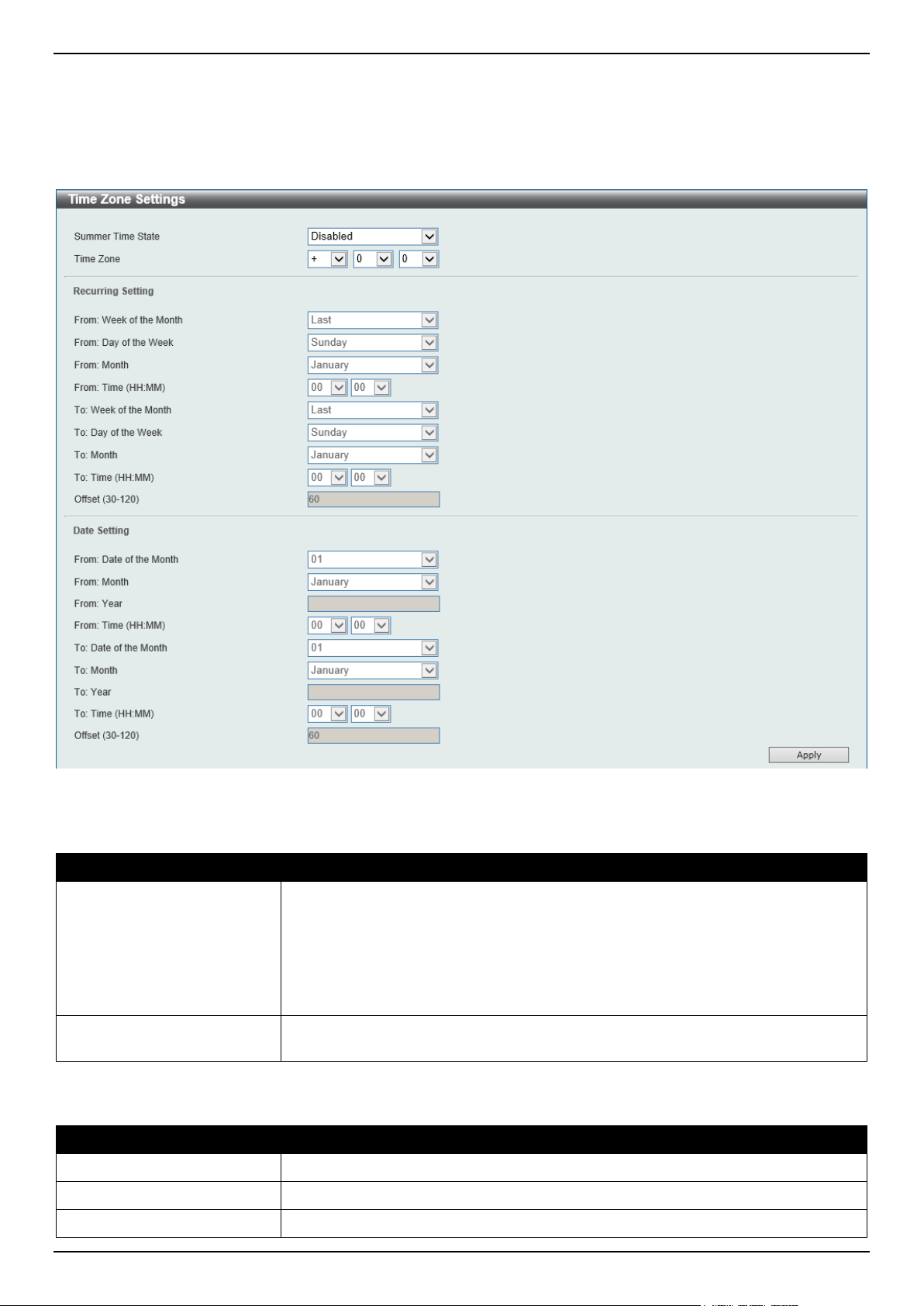
DGS-1520 Series Gigabit Ethernet Smart Managed Switch Web UI Reference Guide
30
Time Zone Settings
This window is used to display and configure time zones and Daylight Savings Time settings for SNTP.
To view the following window, click System > Time and SNTP > Time Zone Settings, as shown below:
Figure 3-26 Time Zone Settings Window
The fields that can be configured are described below:
Parameter Description
Summer Time State
Select the summer time setting. Options to choose from are:
• Disabled - Select to disable the summer time setting.
• Recurring Setting - Select to configure the summer time that should start
and end on the specified weekday of the specified month.
• Date Setting - Select to configure the summer time that should start and
end on the specified date of the specified month.
Time Zone
Select to specify your local time zone offset from Coordinated Universal Time
(UTC).
The fields that can be configured in Recurring Settings are described below:
Parameter Description
From: Week of the Month
Select week of the month that summer time will start.
From: Day of the Week
Select the day of the week that summer time will start.
From: Month
Select the month that summer time will start.
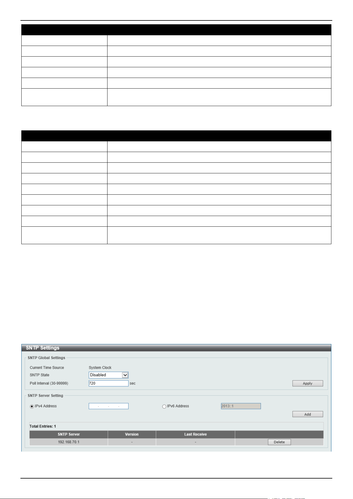
DGS-1520 Series Gigabit Ethernet Smart Managed Switch Web UI Reference Guide
31
Parameter Description
From: Time
Select the time of the day that summer time will start.
To: Week of the Month
Select week of the month that summer time will end.
To: Day of the Week
Select the day of the week that summer time will end.
To: Month
Select the month that summer time will end.
To: Time
Select the time of the day that summer time will end.
Offset
Enter the number of minutes to add during summer time. The range of this offset is
30, 60, 90, and 120. By default, this value is 60.
The fields that can be configured in Date Settings are described below:
Parameter Description
From: Date of the Month
Select date of the month that summer time will start.
From: Month
Select the month that summer time will start.
From: Year
Enter the year that the summer time will start.
From: Time
Select the time of the day that summer time will start.
To: Date of the Month
Select date of the month that summer time will end.
To: Month
Select the month that summer time will end.
To: Year
Enter the year that the summer time will end.
To: Time
Select the time of the day that summer time will end.
Offset
Enter the number of minutes to add during summer time. The range of this offset is
30, 60, 90, and 120. By default, this value is 60.
Click the Apply button to accept the changes made.
SNTP Settings
The Simple Network Time Protocol (SNTP) is a protocol for synchronizing computer clocks through the Internet. It
provides comprehensive mechanisms to access national time and frequency dissemination services, coordinate the
SNTP subnet of servers and clients, and adjust the system clock on each participant.
This window is used to display and configure the SNTP settings for the Switch.
To view the following window, click System > Time and SNTP > SNTP Settings, as shown below:
Figure 3-27 SNTP Settings Window
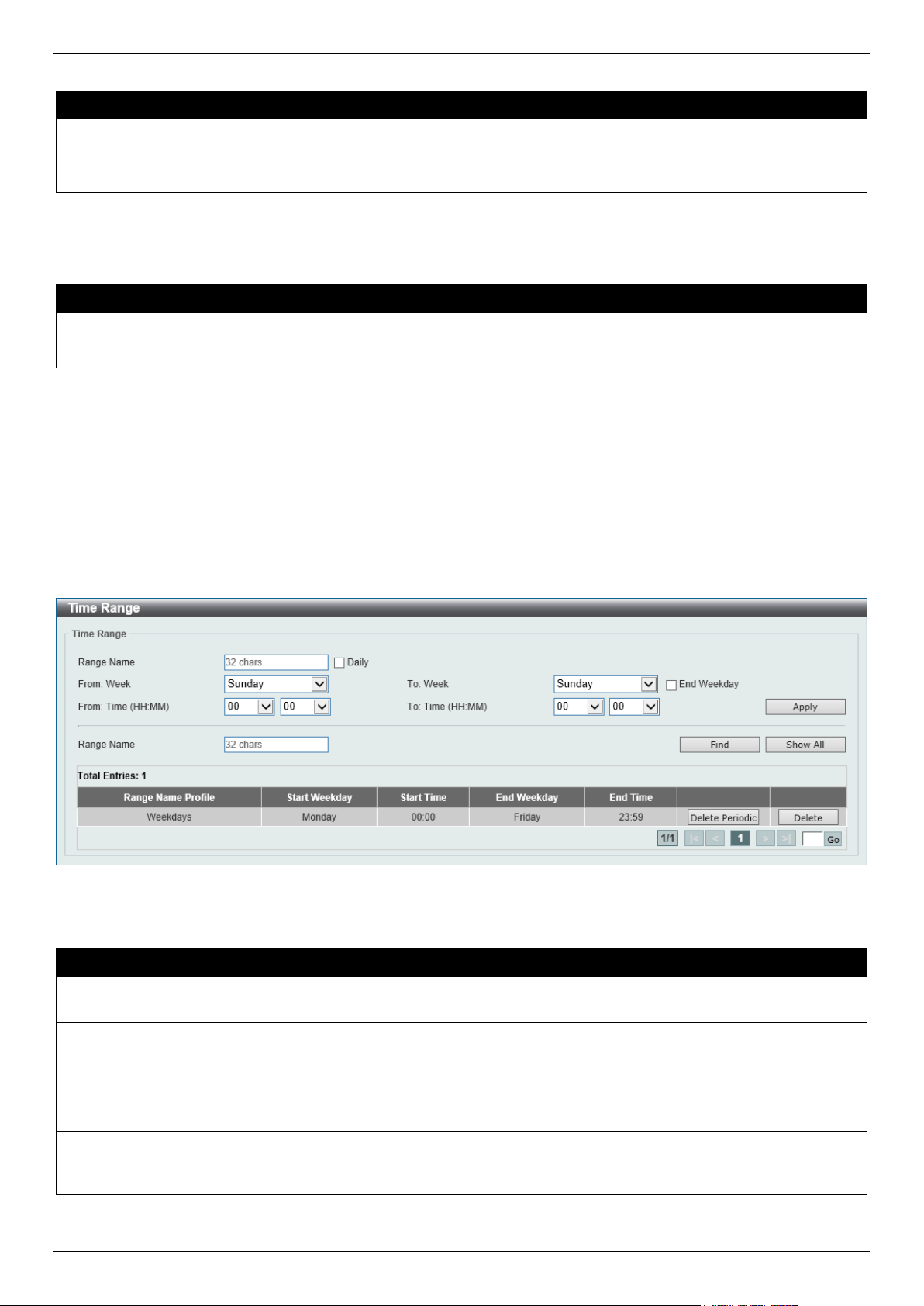
DGS-1520 Series Gigabit Ethernet Smart Managed Switch Web UI Reference Guide
32
The fields that can be configured in SNTP Global Settings are described below:
Parameter Description
SNTP State
Select this option to enable or disable SNTP.
Poll Interval
Enter the synchronizing interval in seconds. The value is from 30 to 99999
seconds. By default, this value is 720 seconds.
Click the Apply button to accept the changes made.
The fields that can be configured in SNTP Server Settings are described below:
Parameter Description
IPv4 Address
Enter the IPv4 address of the SNTP server, which provides the SNTP reference.
IPv6 Address
Enter the IPv6 address of the SNTP server, which provides the SNTP reference.
Click the Add button to add the SNTP server.
Click the Delete button to remove the specified entry.
Time Range
This window is used to display and configure the time profile settings.
To view the following window, click System > Time Range, as shown below:
Figure 3-28 Time Range Window
The fields that can be configured are described below:
Parameter Description
Range Name
Enter the time profile range name here. This name can be up to 32 characters
long.
From Week ~ To Week
Select the starting and ending days of the week that will be used for this time
profile.
Tick the Daily option to use this time profile for every day of the week.
Tick the End Week Day option to use this time profile from the starting day of the
week until the end of the week.
From Time ~ To Time
Select the starting and ending time of the day that will be used for this time profile.
The first drop-down menu selects the hour and the second drop-down menu
selects the minute.
Click the Apply button to accept the changes made.
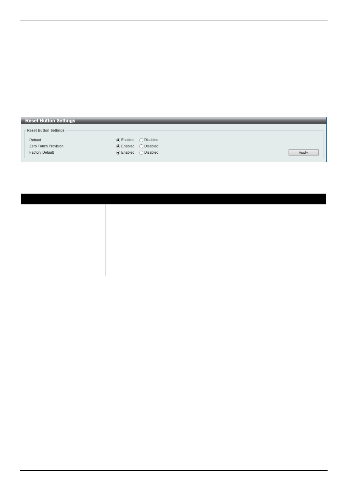
DGS-1520 Series Gigabit Ethernet Smart Managed Switch Web UI Reference Guide
33
Click the Find button to locate a specific entry based on the information entered.
Click the Delete Periodic button to delete the periodic entry.
Click the Delete button to delete the specified entry.
Reset Button Settings
This window is used to configure the Reset button settings.
To view the following window, click System > Reset Button Settings, as shown below:
Figure 3-29 Reset Button Settings Window
The fields that can be configured are described below:
Parameter Description
Reboot
Select to enable or disable the reboot state of the reset button on the Switch.
When enabled, pressing the reset button on the Switch within 5 seconds will
reboot the Switch.
Zero Touch Provision
Select to enable or disable the ZTP state of the reset button on the Switch. When
enabled, pressing the reset button on the Switch between 5 and 10 seconds will
initiate ZTP.
Factory Default
Select to enable or disable the factory reset state of the reset button on the Switch.
When enabled, pressing the reset button on the Switch more than 10 seconds will
reset the Switch to factory defaults.
Click the Apply button to accept the changes made.

DGS-1520 Series Gigabit Ethernet Smart Managed Switch Web UI Reference Guide
34
4. Management
Command Logging
User Accounts Settings
Password Encryption
Password Recovery
Login Method
SNMP
RMON
Telnet/Web
Session Timeout
DHCP
DHCP Auto Configuration
DHCP Auto Image Settings
DNS
NTP
IP Source Interface
File System
Stacking
Virtual Stacking (SIM)
D-Link Discovery Protocol
SMTP Settings
NLB FDB Settings
Command Logging
This window is used to display and configure the command logging function. The command logging function is used to
log the commands that have successfully been configured on the Switch via the command line interface. The
command, along with information about the user that entered the command, is included in the system log. Commands
that do not cause a change in the Switch configuration or operation (such as 'show' commands) are not logged.
To view the following window, click Management > Command Logging, as shown below:
Figure 4-1 Command Logging Window
The fields that can be configured are described below:
Parameter Description
Command Logging State
Select to enable or disable the command logging function here.
Click the Apply button to accept the changes made.
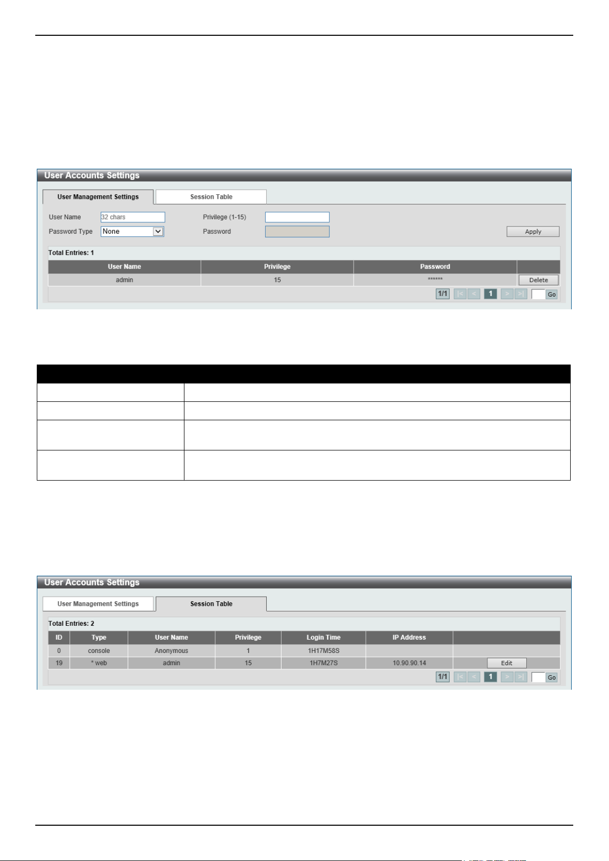
DGS-1520 Series Gigabit Ethernet Smart Managed Switch Web UI Reference Guide
35
User Accounts Settings
On this page, user accounts can be created and updated. Active user account sessions can also be viewed on this
page. There are several configuration options available in the Web User Interface (Web UI). The set of configuration
options available to the user depends on the account's Privilege Level.
To view the following window, click Management > User Accounts Settings, as shown below:
After selecting the User Management Settings tab, the following page will appear.
Figure 4-2 User Accounts Settings Window
The fields that can be configured are described below:
Parameter Description
User Name
Enter the user account name here. This name can be up to 32 characters long.
Privilege
Enter the privilege level for this account here. The range is from 1 to 15.
Password Type
Select the password type for this user account here. Options to choose from are
None, Plain Text, Encrypted-SHA1, and Encrypted-MD5.
Password After selecting Plain Text, Encrypted-SHA1, or Encrypted-MD5 as the password
type, enter the password for this user account here.
Click the Apply button to accept the changes made.
Click the Delete button to delete the specified user account entry.
Enter a page number and click the Go button to navigate to a specific page when multiple pages exist.
After selecting the Session Table tab, the following page will appear.
Figure 4-3 Session Table Window
On this page, a list of active user account session will be displayed.
Click the Edit button to access and configure the User Privilege settings.
Enter a page number and click the Go button to navigate to a specific page when multiple pages exist.
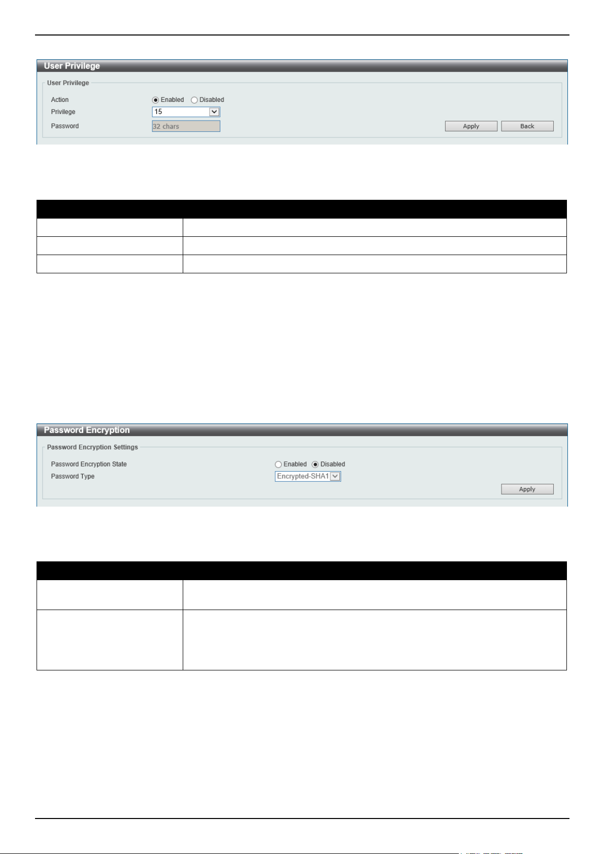
DGS-1520 Series Gigabit Ethernet Smart Managed Switch Web UI Reference Guide
36
After selecting the Edit button, the following page will appear.
Figure 4-4 User Privilege Window
The fields that can be configured are described below:
Parameter Description
Action
Select to enable or disable user level security.
Privilege
Select the privilege level here. The range is from 1 to 15.
Password
Enter the password here. This can be up to 32 characters long.
Click the Apply button to accept the changes made.
Click the Back button to return to the previous page.
Password Encryption
This window is used to display and configure whether to save the encryption of the password in the configuration file.
To view the following window, click Management > Password Encryption, as shown below:
Figure 4-5 Password Encryption Window
The fields that can be configured are described below:
Parameter Description
Password Encryption State
Select this option to enable or disable the encryption of the password before being
stored in the configuration file.
Password Type
When the state is enabled, select the password encryption type here. Options to
choose from are:
• Encrypted-SHA1 - Specifies that the password is encrypted using SHA-1.
• Encrypted-MD5 - Specifies that the password is encrypted using MD5.
Click the Apply button to accept the changes made.
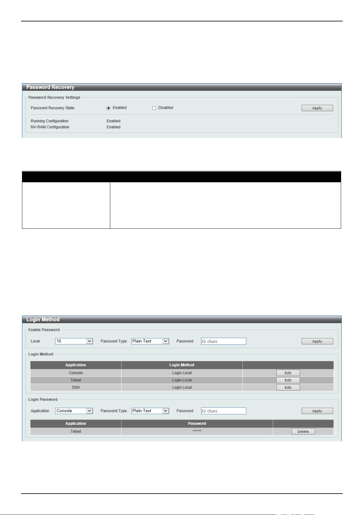
DGS-1520 Series Gigabit Ethernet Smart Managed Switch Web UI Reference Guide
37
Password Recovery
This window is used to display and configure the password recovery settings. For example, the administrator may
need to update a user account because the password has been forgotten.
To view the following window, click Management > Password Recovery, as shown below:
Figure 4-6 Password Recovery Window
The fields that can be configured are described below:
Parameter Description
Password Recovery State
Select to enable or disable the password recovery feature here. Enabling this
feature allows access to the reset configuration mode in the CLI. From the reset
configuration mode, user accounts can be updated, the enable password feature
can be updated for administrator privilege levels, and the AAA feature can be
disabled to allow local authentication. The running configuration can then be saved
as the startup configuration. A reboot is required.
Click the Apply button to accept the changes made.
Login Method
This window is used to display and configure the login method for each management interface that is supported by the
Switch.
To view the following window, click Management > Login Method, as shown below:
Figure 4-7 Login Method Window

DGS-1520 Series Gigabit Ethernet Smart Managed Switch Web UI Reference Guide
38
The fields that can be configured in Enable Password are described below:
Parameter Description
Level
Select the privilege level for the user here. The range is from 1 to 15.
Password Type
Select the password type for the user here. Options to choose from are:
• Plain Text - Specifies that the password will be in plain text.
• Encrypted-SHA1 - Specifies that the password will be encrypted based on
SHA-1.
• Encrypted-MD5 - Specifies that the password will be encrypted based on
MD5.
By default, the Plain Text option is used.
Password
Enter the password for the user account here. In the plain-text form, the password
can be up to 32 characters long, is case-sensitive, and can contain spaces. In the
encrypted form, the password must be 35 bytes long and is case-sensitive. In the
encrypted MD5 form, the password must be 31 bytes long and is case-sensitive.
Click the Apply button to accept the changes made.
Click the Edit button to re-configure the specified entry.
The fields that can be configured in Login Method are described below:
Parameter Description
Login Method After clicking the Edit button, this parameter can be configured. Select the login
method for the specified application here. Options to choose from are:
• No Login requires no login authentication to access the specified
application.
• Login will require the user to at least enter a password when trying to
access the application specified.
• Login Local requires the user to enter a username and a password to
access the specified application.
Click the Apply button to accept the changes made.
The fields that can be configured in Login Password are described below:
Parameter Description
Application
Select the application that will be configured here. Options to choose from are
Console, Telnet and SSH.
Password Type
Select the password encryption type that will be used here. Options to choose from
are Plain Text, Encrypted-SHA1, and Encrypted-MD5.
Password
Enter the password for the selected application here. This password will be used
when the Login Method for the specified application is set as Login.
In the plain-text form, the password can be up to 32 characters long, is case-
sensitive, and can contain spaces.
In the encrypted form, the password must be 35 bytes long and is case-sensitive.
In the encrypted MD5 form, the password must be 31 bytes long and is case-
sensitive.
Click the Apply button to accept the changes made.
Click the Delete button to remove the password from the specified application.

DGS-1520 Series Gigabit Ethernet Smart Managed Switch Web UI Reference Guide
39
SNMP
Simple Network Management Protocol (SNMP) is an OSI Layer 7 (Application Layer) designed specifically for
managing and monitoring network devices. SNMP enables network management stations to read and modify the
settings of gateways, routers, switches, and other network devices. Use SNMP to configure system features, monitor
performance, and detect potential problems with the Switch, switch group, or network.
Managed devices that support SNMP include software (referred to as an agent) which runs locally on the device. A
defined set of variables (managed objects) is maintained by the SNMP agent and used to manage the device. These
objects are defined in a Management Information Base (MIB), which provides a standard presentation of the
information controlled by the on-board SNMP agent. SNMP defines both the format of the MIB specifications and the
protocol used to access this information over the network.
The Switch supports the SNMP versions 1, 2c, and 3. The three versions of SNMP vary in the level of security
provided between the management station and the network device.
In SNMPv1 and SNMPv2c, user authentication is accomplished using 'community strings', which function like
passwords. The remote user SNMP application and the Switch SNMP must use the same community string. SNMP
packets from any station that has not been authenticated are ignored (dropped). The default community strings for the
Switch used for SNMPv1 and SNMPv2c management access are:
• public - Allows authorized management stations to retrieve MIB objects.
• private - Allows authorized management stations to retrieve and modify MIB objects.
The SNMPv3 protocol uses a more sophisticated authentication process that is separated into two parts. The first part
maintains a list of users and their attributes that are allowed to act as SNMP managers. The second part describes
what each user in that list can do as an SNMP manager. The SNMPv3 protocol also provides an additional layer of
security that can be used to encrypt SNMP messages.
The Switch allows groups of users to be listed and configured with a shared set of privileges. The SNMP version may
also be set for a listed group of SNMP managers. Thus, you may create a group of SNMP managers that are allowed
to view read-only information or receive traps using SNMPv1 while assigning a higher level of security to another
group, granting read/write privileges using SNMPv3.
Using SNMPv3, users or groups can be allowed or be prevented from performing specific SNMP management
functions. These are defined using the Object Identifier (OID) associated with a specific MIB.
MIBs
A Management Information Base (MIB) stores management and counter information. The Switch uses the standard
MIB-II Management Information Base module, and so values for MIB objects can be retrieved using any SNMP-based
network management software. In addition to the standard MIB-II, the Switch also supports its own proprietary
enterprise MIB as an extended Management Information Base. Specifying the MIB Object Identifier may also retrieve
the proprietary MIB. MIB values can be either read-only or read-write.
The Switch incorporates a flexible SNMP management system, which can be customized to suit the needs of the
networks and the preferences of the network administrator. The three versions of SNMP vary in the level of security
provided between the management station and the network device. SNMP settings are configured using the menus
located in the SNMP folder of the Web UI.
Traps
Traps are messages that alert network personnel of events that occur on the Switch. The events can be as serious as
a reboot (someone accidentally turned the Switch off/unplugged the Switch), or less serious like a port status change.
The Switch generates traps and sends them to the trap recipient (or network manager). Typical traps include trap
messages for Authentication Failure, Topology Change, and Broadcast/Multicast Storm.
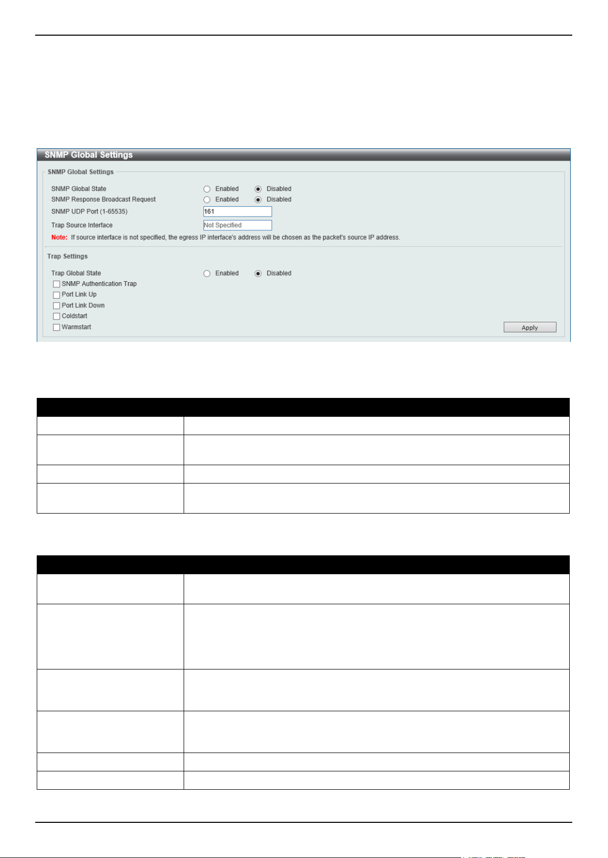
DGS-1520 Series Gigabit Ethernet Smart Managed Switch Web UI Reference Guide
40
SNMP Global Settings
This window is used to display and configure the global SNMP and trap settings.
To view the following window, click Management > SNMP > SNMP Global Settings, as shown below:
Figure 4-8 SNMP Global Settings Window
The fields that can be configured in SNMP Global Settings are described below:
Parameter Description
SNMP Global State
Select this option to enable or disable the SNMP feature.
SNMP Response Broadcast
Request
Select this option to enable or disable the server to response to broadcast SNMP
GetRequest packets.
SNMP UDP Port
Enter the SNMP UDP port number.
Trap Source Interface
Enter the interface whose IP address will be used as the source address for
sending the SNMP trap packet.
The fields that can be configured in Trap Settings are described below:
Parameter Description
Trap Global State
Select this option to enable or disable the sending of all or specific SNMP
notifications.
SNMP Authentication Trap
Tick this option to control the sending of SNMP authentication failure notifications.
An authenticationFailuretrap trap is generated when the device receives an SNMP
message that is not properly authenticated. The authentication method depends
on the version of SNMP being used. For SNMPv1 or SNMPv2c, authentication
failure occurs if packets are formed with an incorrect community string.
Port Link Up Tick this option to control the sending of port link up notifications. A linkUp trap is
generated when the device recognizes that one of the communication links has
come up.
Port Link Down Tick this option to control the sending of port link down notifications. A linkDown
trap is generated when the device recognizes that a one of the communication
links is down.
Coldstart Tick this option to control the sending of SNMP coldStart notifications.
Warmstart Tick this option to control the sending of SNMP warmStart notifications.
Click the Apply button to accept the changes made.
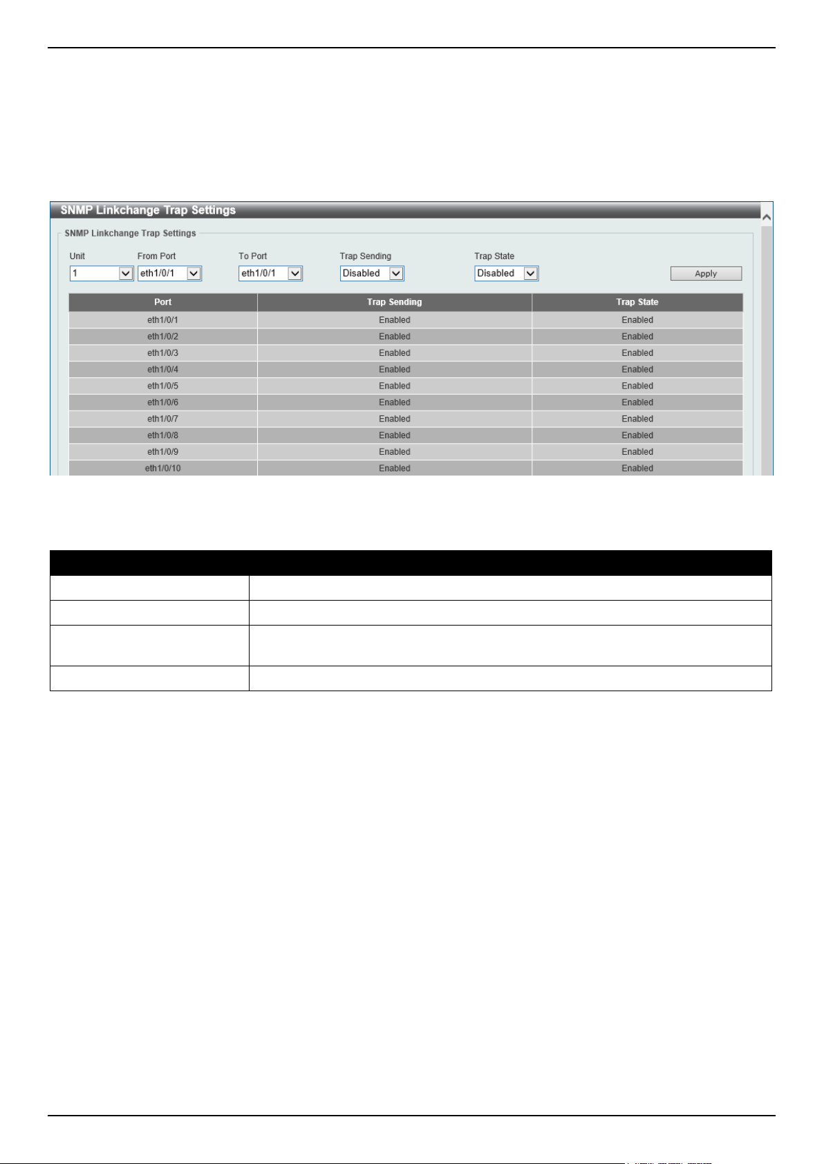
DGS-1520 Series Gigabit Ethernet Smart Managed Switch Web UI Reference Guide
41
SNMP Linkchange Trap Settings
This window is used to display and configure the SNMP link change trap settings.
To view the following window, click Management > SNMP > SNMP Linkchange Trap Settings, as shown below:
Figure 4-9 SNMP Linkchange Trap Settings Window
The fields that can be configured are described below:
Parameter Description
Unit
Select the Switch unit that will be used for this configuration here.
From Port - To Port
Select the appropriate port range used for the configuration here.
Trap Sending
Select this option to enable or disable the sending of the SNMP notification traps
that are generated by the system.
Trap State Select this option to enable or disable the SNMP linkChange trap.
Click the Apply button to accept the changes made.
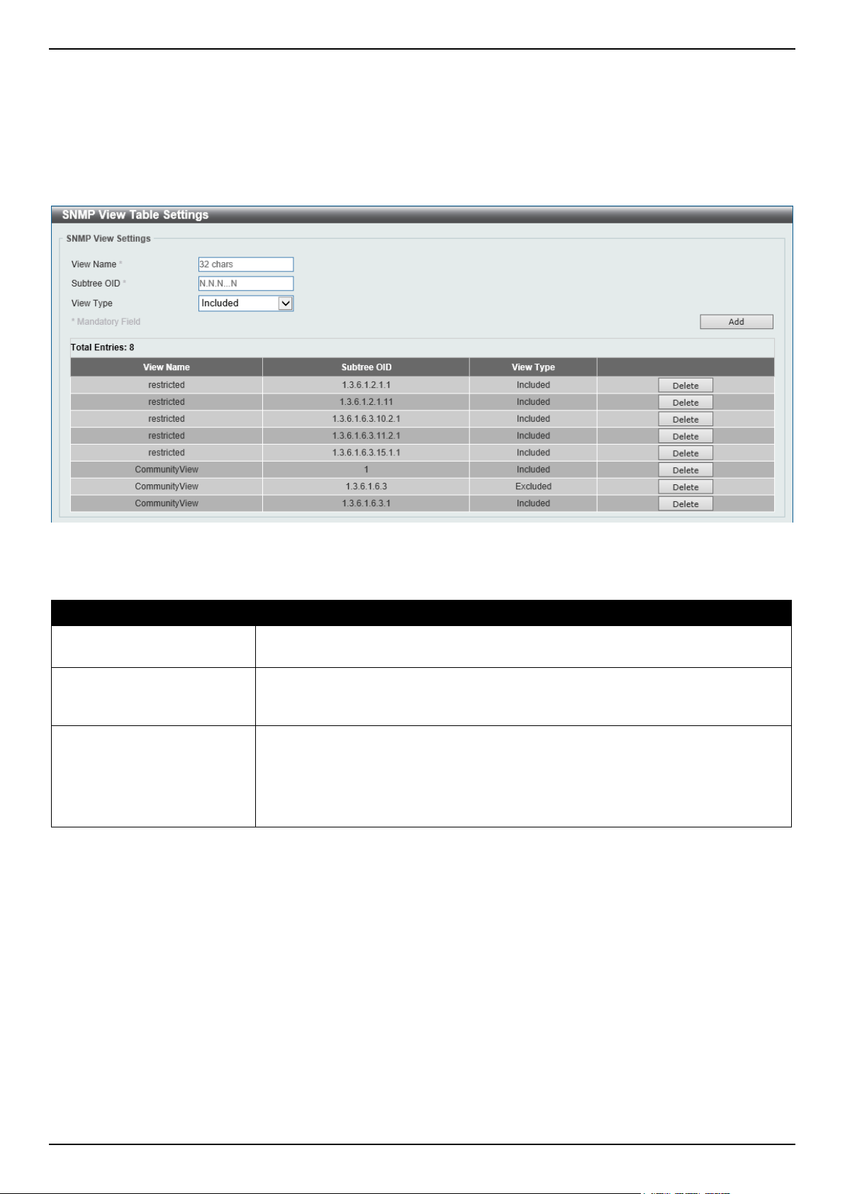
DGS-1520 Series Gigabit Ethernet Smart Managed Switch Web UI Reference Guide
42
SNMP View Table Settings
This window is used to assign views to community strings that define which MIB objects can be accessed by a remote
SNMP manager. The SNMP sub-tree OID created with this table maps SNMP users to the views created in the SNMP
User Table Settings window.
To view the following window, click Management > SNMP > SNMP View Table Settings, as shown below:
Figure 4-10 SNMP View Table Settings Window
The fields that can be configured are described below:
Parameter Description
View Name
Type an alphanumeric string of up to 32 characters. This is used to identify the
new SNMP view being created.
Subtree OID
Type the Object Identifier (OID) sub-tree for the view. The OID identifies an object
tree (MIB tree) that will be included or excluded from access by an SNMP
manager.
View Type
Select the view type here. Options to choose from are:
• Included - Select to include this object in the list of objects that an SNMP
manager can access.
• Excluded - Select to exclude this object from the list of objects that an
SNMP manager can access.
Click the Add button to add a new entry based on the information entered.
Click the Delete button to remove the specified entry.
SNMP Community Table Settings
This window is used to create an SNMP community string to define the relationship between the SNMP manager and
an agent. The community string acts like a password to permit access to the agent on the Switch. One or more of the
following characteristics can be associated with the community string:
• An access list containing IP addresses of SNMP managers that are permitted to use the community string to
gain access to the Switch's SNMP agent.
• Any MIB view that defines the subset of MIB objects that will be accessible to the SNMP community.
• Read-write or read-only level permissions for the MIB objects accessible to the SNMP community.
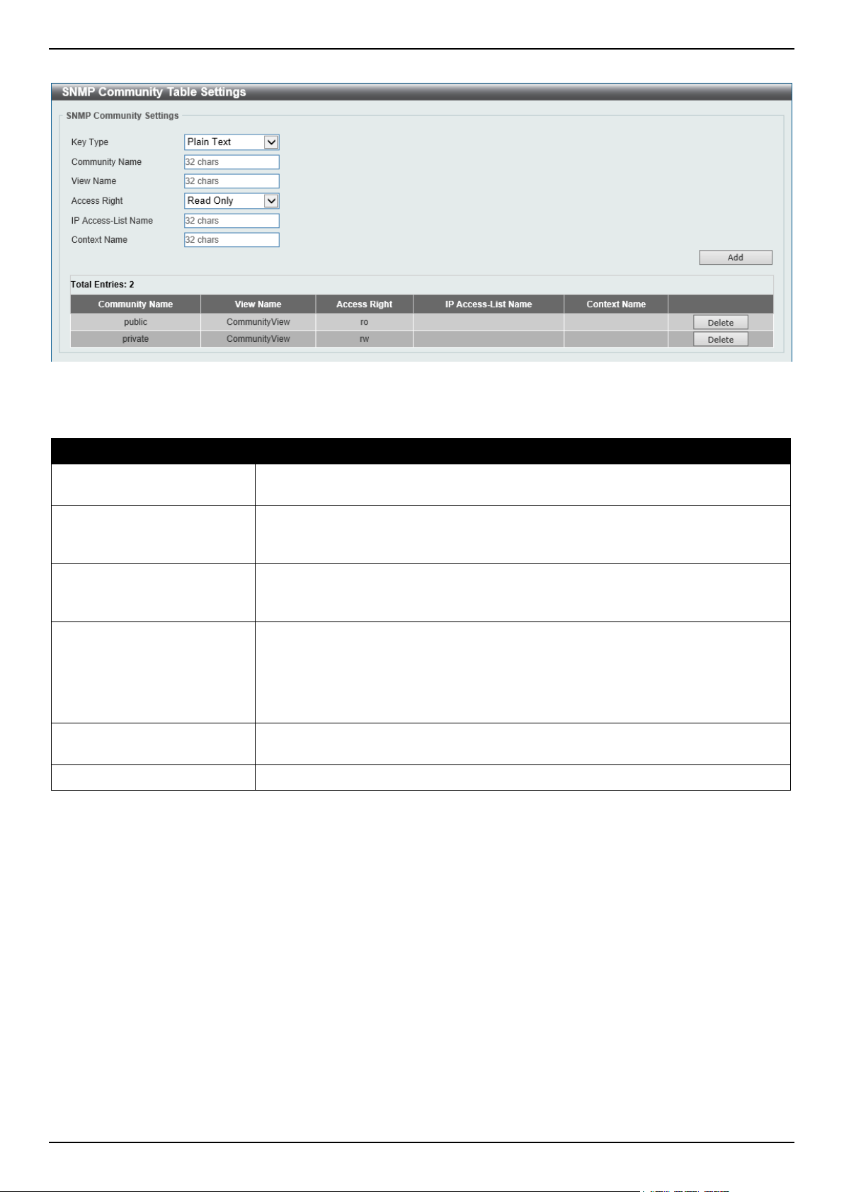
DGS-1520 Series Gigabit Ethernet Smart Managed Switch Web UI Reference Guide
43
To view the following window, click Management > SNMP > SNMP Community Table Settings, as shown below:
Figure 4-11 SNMP Community Table Settings Window
The fields that can be configured are described below:
Parameter Description
Key Type Select the key type for the SNMP community. Options to choose from are Plain
Text, and Encrypted.
Community Name
Enter an alphanumeric string of up to 32 characters that is used to identify
members of an SNMP community. This string is used like a password to give
remote SNMP managers access to MIB objects in the Switch's SNMP agent.
View Name
Enter an alphanumeric string of up to 32 characters that is used to identify the
group of MIB objects that a remote SNMP manager is allowed to access on the
Switch. The view name must exist in the SNMP View Table.
Access Right
Select the access right here. Options to choose from are:
• Read Only - SNMP community members using the community string
created can only read the contents of the MIBs on the Switch.
• Read Write - SNMP community members using the community string
created can read from, and write to the contents of the MIBs on the Switch.
IP Access-List Name
Enter the name of the standard access list to restrict the users that can use this
community string to access to the SNMP agent.
Context Name
Enter the context name here. This name can be up to 32 characters long.
Click the Add button to add a new entry based on the information entered.
Click the Delete button to remove the specified entry.
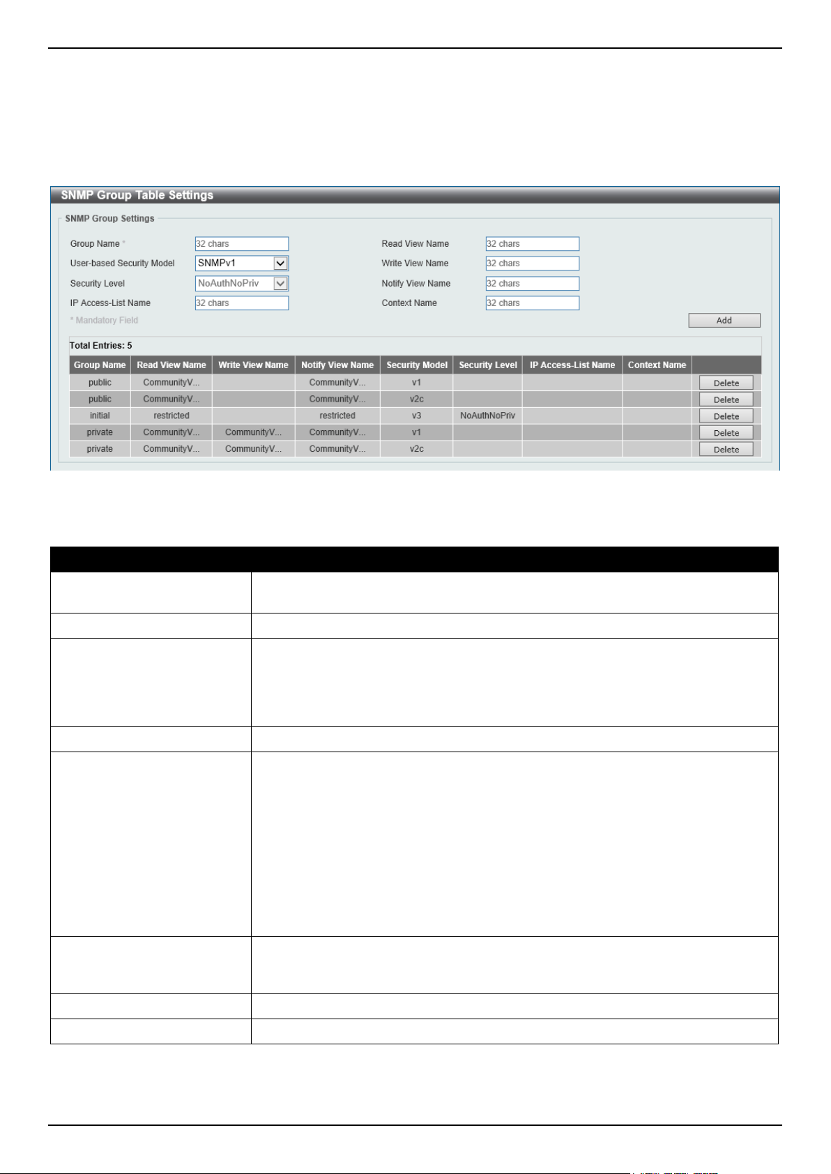
DGS-1520 Series Gigabit Ethernet Smart Managed Switch Web UI Reference Guide
44
SNMP Group Table Settings
An SNMP group created with this table maps SNMP users to the views created in the SNMP View Table Settings
window.
To view the following window, click Management > SNMP > SNMP Group Table Settings, as shown below:
Figure 4-12 SNMP Group Table Settings Window
The fields that can be configured are described below:
Parameter Description
Group Name
Enter the SNMP group name here. This name can be up to 32 characters long.
Spaces are not allowed.
Read View Name
Enter the read view name that users of the group can access.
User-based Security Model
Select the security model here. Options to choose from are:
• SNMPv1 - Select to allow the group to use the SNMPv1 security model.
• SNMPv2c - Select to allow the group to use the SNMPv2c security model.
• SNMPv3 - Select to allow the group to use the SNMPv3 security model.
Write View Name
Enter the write view name that the users of the group can access.
Security Level When selecting SNMPv3 in the User-based Security Model drop-down list, this
option is available.
• NoAuthNoPriv - Specify that there will be no authorization and no
encryption of packets sent between the Switch and a remote SNMP
manager.
• AuthNoPriv - Specify that authorization will be required, but there will be no
encryption of packets sent between the Switch and a remote SNMP
manager.
• AuthPriv - Specify that authorization will be required, and that packets sent
between the Switch and a remote SNMP manger will be encrypted.
Notify View Name
Enter the notify view name that users of the group can access. The notify view
describes the object that can be reported its status via trap packets to the group
user.
IP Access-List Name
Enter the standard IP access control list (ACL) to associate with the group.
Context Name
Enter the context name here. This name can be up to 32 characters long.
Click the Add button to add a new entry based on the information entered.
Click the Delete button to remove the specified entry.
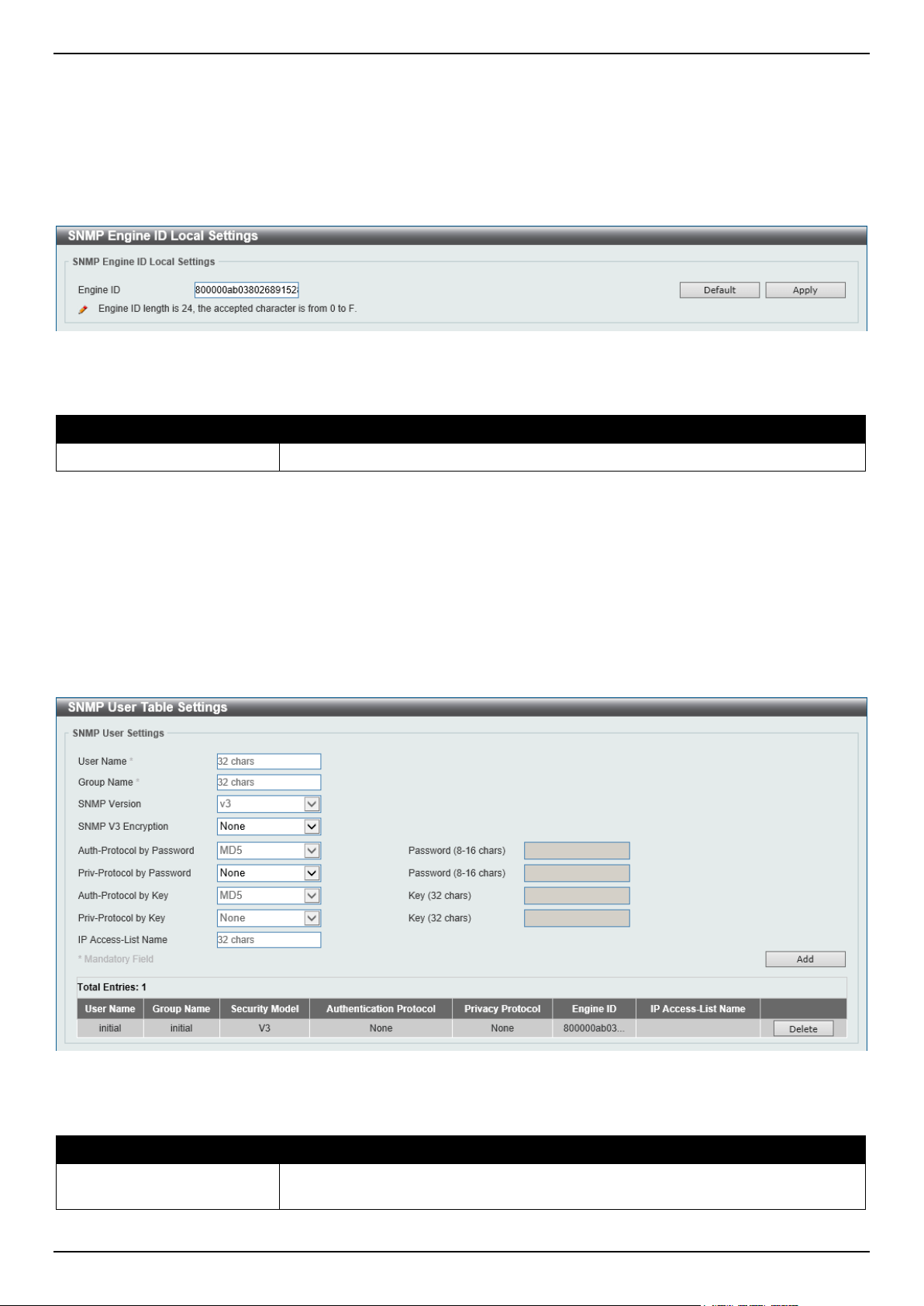
DGS-1520 Series Gigabit Ethernet Smart Managed Switch Web UI Reference Guide
45
SNMP Engine ID Local Settings
The Engine ID is a unique identifier used for SNMPv3 implementations on the Switch.
To view the following window, click Management > SNMP > SNMP Engine ID Local Settings, as shown below:
Figure 4-13 SNMP Engine ID Local Settings Window
The fields that can be configured are described below:
Parameter Description
Engine ID
Enter the SNMP engine ID string here. This string can be up to 24 characters long.
Click the Default button to revert the engine ID to the default.
Click the Apply button to accept the changes made.
SNMP User Table Settings
This window is used to display and configure the SNMP users that are currently configured on the Switch.
To view the following window, click Management > SNMP > SNMP User Table Settings, as shown below:
Figure 4-14 SNMP User Table Settings Window
The fields that can be configured are described below:
Parameter Description
User Name
Enter SNMP user name here. This name can be up to 32 characters long. This is
used to identify the SNMP user.

DGS-1520 Series Gigabit Ethernet Smart Managed Switch Web UI Reference Guide
46
Parameter Description
Group Name
Enter the SNMP group name to which the user belongs. This name can be up to
32 characters long. Spaces are not allowed.
SNMP Version
Specifies that SNMP version 3 (SNMPv3) is used.
SNMP V3 Encryption Select the SNMPv3 encryption type here. Options to choose from are None,
Password, and Key.
Auth-Protocol by Password After selecting the Password encryption type, select the authentication protocol
here. Options to choose from are:
• MD5 - Specifies to use the HMAC-MD5-96 authentication protocol. Enter the
password in the Password textbox. The password can be from 8 to 16
characters long.
• SHA - Specifies to use the HMAC-SHA authentication protocol. Enter the
password in the Password textbox. The password can be from 8 to 20
characters long.
Priv-Protocol by Password After selecting the Password encryption type, select the private protocol here.
Options to choose from are:
• None - Specifies to use no authorization protocol.
• DES56 - Specifies to use DES 56-bit encryption based on the CBC-DES
(DES-56) standard. Enter the password in the Password textbox. The
password can be from 8 to 16 characters long.
• AES - Specifies to use Advanced Encryption Standard (AES) encryption.
Enter the password in the Password textbox. The password can be from 8
to 16 characters long.
Auth-Protocol by Key After selecting the Key encryption type, select the authentication protocol here.
Options to choose from are:
• MD5 - Specifies to use the HMAC-MD5-96 authentication protocol. Enter the
key in the Key textbox. The key must be 32 characters long.
• SHA - Specifies to use the HMAC-SHA authentication protocol. Enter the
key in the Key textbox. The key must be 40 characters long.
Priv-Protocol by Key After selecting the Key encryption type, select the private protocol here. Options to
choose from are:
• None - Specifies to use no authorization protocol.
• DES56 - Specifies to use DES 56-bit encryption, based on the CBC-DES
(DES-56) standard. Enter the key in the Key textbox. The key must be 32
characters long.
• AES - Specifies to use AES encryption. Enter the key in the Key textbox.
The key must be 32 characters long.
IP Access-List Name
Enter the standard IP access control list to associate with the user.
Click the Add button to add a new entry based on the information entered.
Click the Delete button to remove the specified entry.
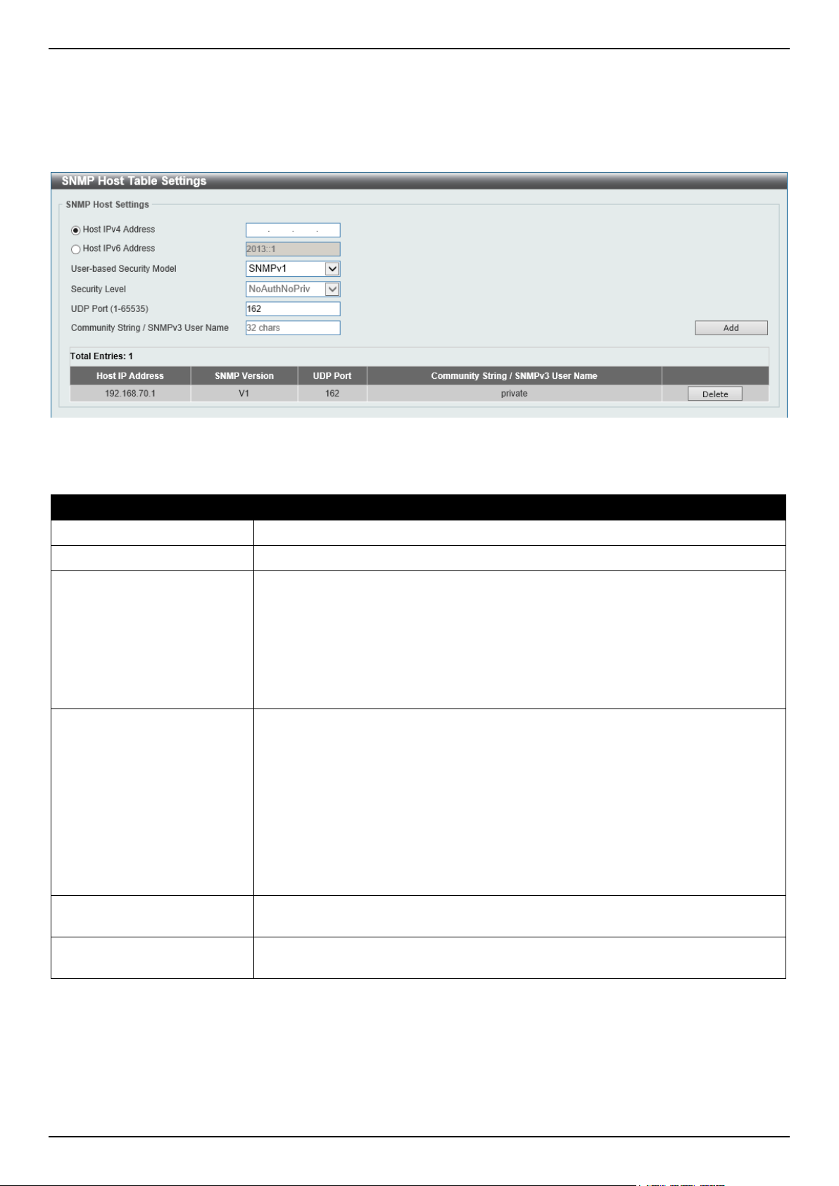
DGS-1520 Series Gigabit Ethernet Smart Managed Switch Web UI Reference Guide
47
SNMP Host Table Settings
This window is used to display and configure the recipient of the SNMP notification.
To view the following window, click Management > SNMP > SNMP Host Table Settings, as shown below:
Figure 4-15 SNMP Host Table Settings Window
The fields that can be configured are described below:
Parameter Description
Host IPv4 Address
Enter the IPv4 address of the SNMP notification host.
Host IPv6 Address
Enter the IPv6 address of the SNMP notification host.
User-based Security Model
Select the security model here. Options to choose from are:
• SNMPv1 - Select to allow the group user to use the SNMPv1 security
model.
• SNMPv2c - Select to allow the group user to use the SNMPv2c security
model.
• SNMPv3 - Select to allow the group user to use the SNMPv3 security
model.
Security Level When selecting SNMPv3 in the User-based Security Model drop-down list, this
option is available.
• NoAuthNoPriv - Specify that there will be no authorization and no
encryption of packets sent between the Switch and a remote SNMP
manager.
• AuthNoPriv - Specify that authorization will be required, but there will be no
encryption of packets sent between the Switch and a remote SNMP
manager.
• AuthPriv - Specify that authorization will be required, and that packets sent
between the Switch and a remote SNMP manger will be encrypted.
UDP Port
Enter the UDP port number. The range of UDP port numbers is from 1 to 65535.
Some port numbers may conflict with other protocols. By default, this value is 162.
Community String /
SNMPv3 User Name
Enter the community string or SNMPv3 user name to be sent with the notification
packet.
Click the Add button to add a new entry based on the information entered.
Click the Delete button to remove the specified entry.
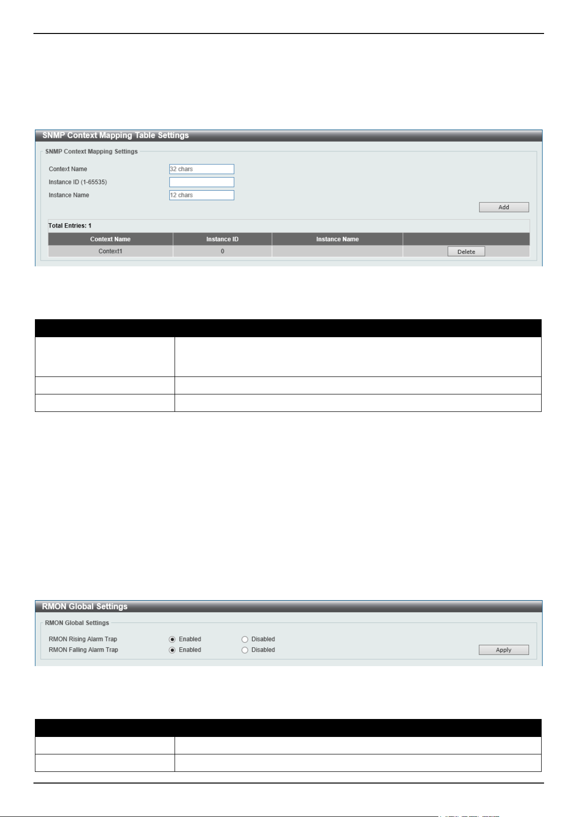
DGS-1520 Series Gigabit Ethernet Smart Managed Switch Web UI Reference Guide
48
SNMP Context Mapping Table Settings
This window is used to display and configure the SNMP context mapping table settings.
To view the following window, click Management > SNMP > SNMP Context Mapping Table Settings, as shown
below:
Figure 4-16 SNMP Context Mapping Table Settings Window
The fields that can be configured are described below:
Parameter Description
Context Name
Enter the SNMP View-based Access Control Model (VACM) context name here.
This name can be up to 32 characters long. The name must start with a letter and
end with a letter or digit. Interior characters can be letters, digits, and hyphens.
Instance ID
Enter the ID of the instance here. The range is from 1 to 65535.
Instance Name
Enter the name of the instance here. This can be up to 12 characters long.
Click the Add button to add a new entry based on the information entered.
Click the Delete button to remove the specified entry.
RMON
RMON Global Settings
This window is used to enable or disable remote monitoring (RMON) for the rising and falling alarm trap feature for the
SNMP function on the Switch.
To view the following window, click Management > RMON > RMON Global Settings, as shown below:
Figure 4-17 RMON Global Settings Window
The fields that can be configured are described below:
Parameter Description
RMON Rising Alarm Trap
Select this option to enable or disable the RMON Rising Alarm Trap Feature.
RMON Falling Alarm Trap
Select this option to enable or disable the RMON Falling Alarm Trap Feature.
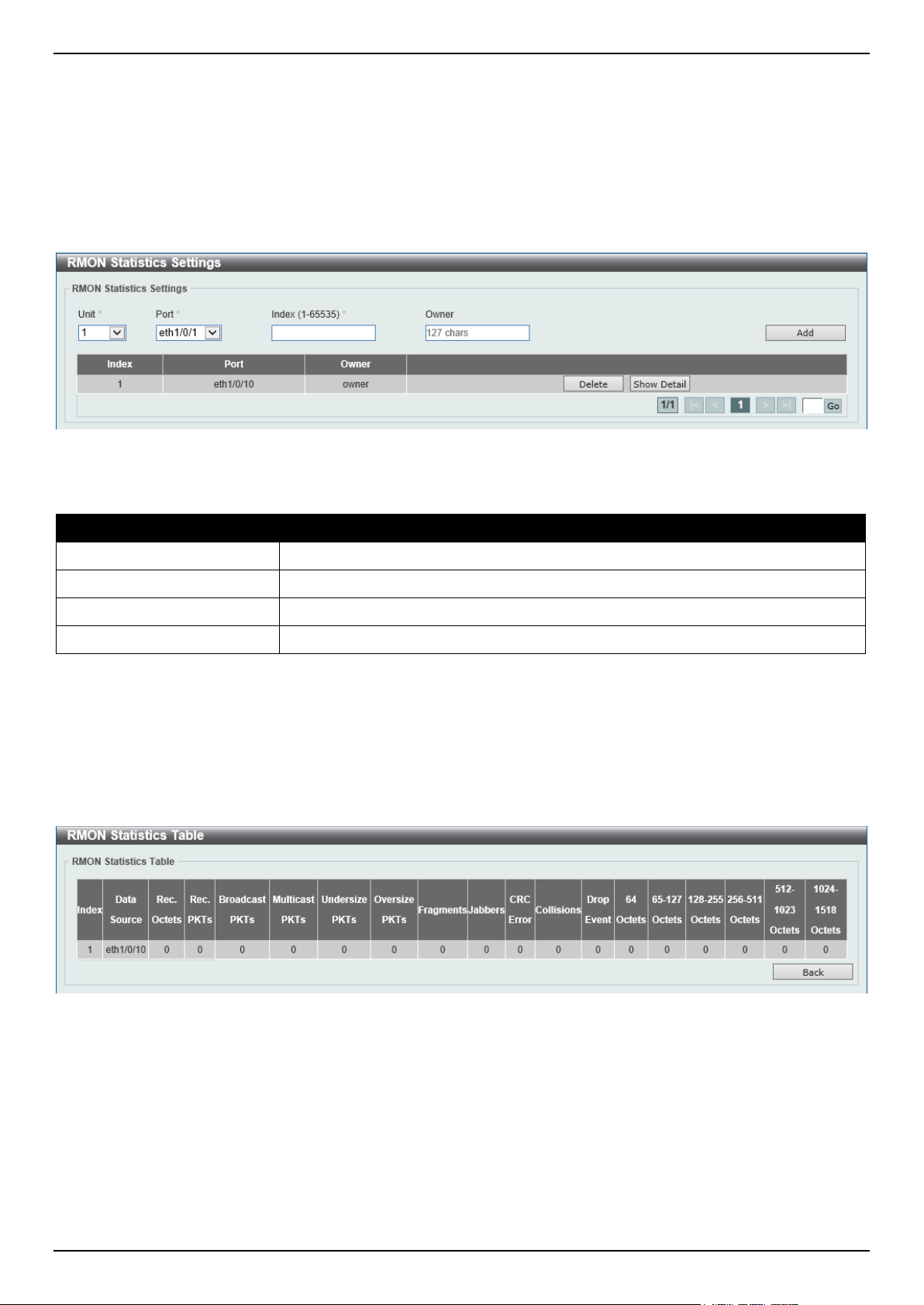
DGS-1520 Series Gigabit Ethernet Smart Managed Switch Web UI Reference Guide
49
Click the Apply button to accept the changes made.
RMON Statistics Settings
This window is used to display and configure the RMON statistics on the specified port.
To view the following window, click Management > RMON > RMON Statistics Settings, as shown below:
Figure 4-18 RMON Statistics Settings Window
The fields that can be configured are described below:
Parameter Description
Unit
Select the Switch unit that will be used for this configuration here.
Port
Select to choose the port.
Index
Enter the RMON table index. The value is from 1 to 65535.
Owner
Enter the owner string. The string can be up to 127 characters.
Click the Add button to add a new entry based on the information entered.
Click the Delete button to remove the specified entry.
Click the Show Detail button to see the detail information of the specific port.
Enter a page number and click the Go button to navigate to a specific page when multiple pages exist.
After clicking the Show Detail button, the following window will appear.
Figure 4-19 RMON Statistics Settings (Show Detail) Window
Click the Back button to return to the previous window.
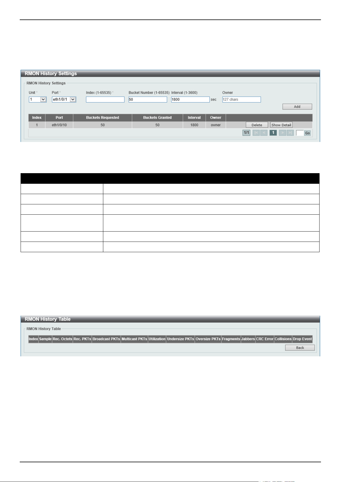
DGS-1520 Series Gigabit Ethernet Smart Managed Switch Web UI Reference Guide
50
RMON History Settings
This window is used to display and configure RMON MIB history statistics gathered on the specified port.
To view the following window, click Management > RMON > RMON History Settings, as shown below:
Figure 4-20 RMON History Settings Window
The fields that can be configured are described below:
Parameter Description
Unit
Select the Switch unit that will be used for this configuration here.
Port
Select the port that will be used here.
Index
Enter the history group table index. The value is from 1 to 65535.
Bucket Number
Enter the number of buckets specified for the RMON collection history group of
statistics. The range is from 1 to 65535. By default, this value is 50.
Interval
Enter the time in seconds in each polling cycle. The range is from 1 to 3600.
Owner
Enter the owner string. The string can be up to 127 characters.
Click the Add button to add a new entry based on the information entered.
Click the Delete button to remove the specified entry.
Click the Show Detail button to see the detail information of the specific port.
Enter a page number and click the Go button to navigate to a specific page when multiple pages exist.
After clicking the Show Detail button, the following window will appear.
Figure 4-21 RMON History Settings (Show Detail) Window
Click the Back button to return to the previous window.
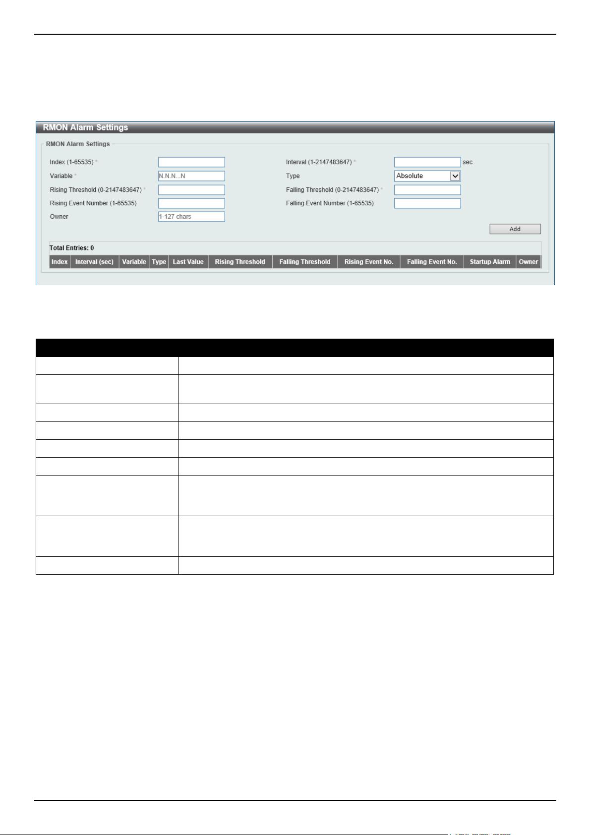
DGS-1520 Series Gigabit Ethernet Smart Managed Switch Web UI Reference Guide
51
RMON Alarm Settings
This window is used to display and configure alarm entries to monitor an interface.
To view the following window, click Management > RMON > RMON Alarm Settings, as shown below:
Figure 4-22 RMON Alarm Settings Window
The fields that can be configured are described below:
Parameter Description
Index
Enter the alarm index. The range is from 1 to 65535.
Interval
Enter the interval in seconds for the sampling of the variable and checking against
the threshold. The range is from 1 to 2147483647 seconds.
Variable
Enter the object identifier of the variable to be sampled.
Type Select the monitoring type. Options to choose from are Absolute and Delta.
Rising Threshold
Enter the rising threshold value between 0 and 2147483647.
Falling Threshold
Enter the falling threshold value between 0 and 2147483647.
Rising Event Number
Enter the index of the event entry that is used to notify the rising threshold-crossing
event. The range is from 1 to 65535. If not specified, no action is taken while
crossing the ringing threshold.
Falling Event Number
Enter the index of the event entry that is used to notify the falling threshold-
crossing event. The range is from 1 to 65535. If not specified, no action is taken
while crossing the falling threshold.
Owner
Enter the owner string up to 127 characters.
Click the Add button to add a new entry based on the information entered.
Click the Delete button to remove the specified entry.
Enter a page number and click the Go button to navigate to a specific page when multiple pages exist.
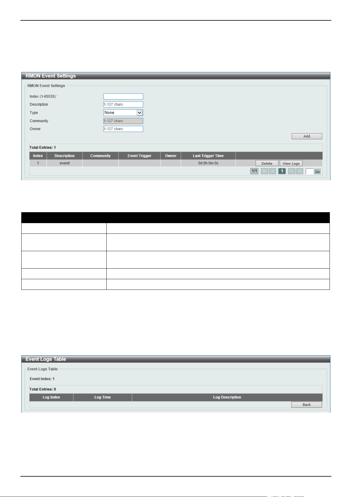
DGS-1520 Series Gigabit Ethernet Smart Managed Switch Web UI Reference Guide
52
RMON Event Settings
This window is used to display and configure event entries.
To view the following window, click Management > RMON > RMON Event Settings, as shown below:
Figure 4-23 RMON Event Settings Window
The fields that can be configured are described below:
Parameter Description
Index
Enter the index value of the alarm entry here. The range is from 1 to 65535.
Description
Enter a description for the RMON event entry. The string is up to 127 characters
long.
Type Select the RMON event entry type. Options to choose from are None, Log, Trap,
and Log and Trap.
Community
Enter the community string. The string can be up to 127 characters.
Owner
Enter the owner string. The string can be up to 127 characters.
Click the Add button to add a new entry based on the information entered.
Click the Delete button to remove the specified entry.
Click the View Logs button to see the detail information of the specific port.
Enter a page number and click the Go button to navigate to a specific page when multiple pages exist.
After clicking the View Logs button, the following window will appear.
Figure 4-24 RMON Event Settings (View Logs) Window
Click the Back button to return to the previous window.
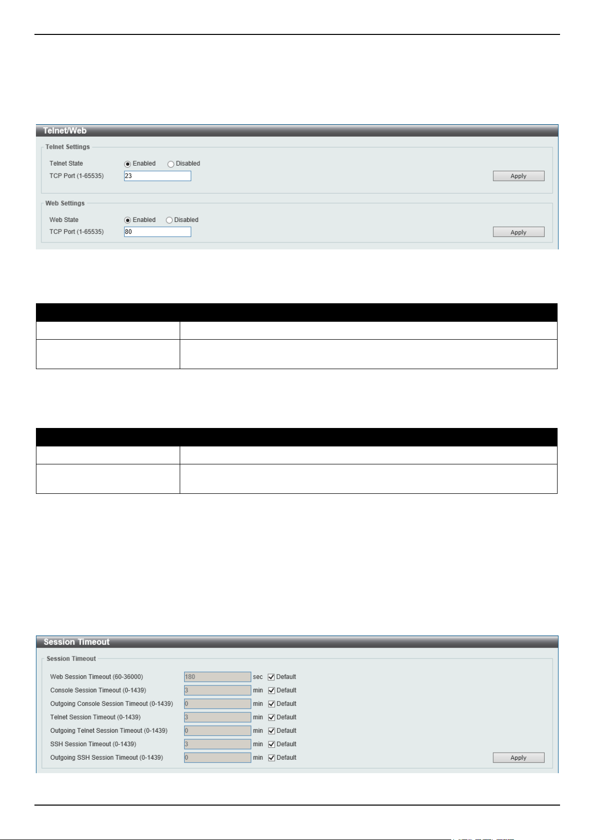
DGS-1520 Series Gigabit Ethernet Smart Managed Switch Web UI Reference Guide
53
Telnet/Web
This window is used to display and configure Telnet and Web settings on the Switch.
To view the following window, click Management > Telnet/Web, as shown below:
Figure 4-25 Telnet/Web Window
The fields that can be configured in Telnet Settings are described below:
Parameter Description
Telnet State
Select to enable or disable the Telnet server feature here.
Port
Enter the TCP port number used for Telnet management of the Switch. The well-
known TCP port for the Telnet protocol is 23.
Click the Apply button to accept the changes made.
The fields that can be configured in Web Settings are described below:
Parameter Description
Web State
Select this option to enable or disable the configuration through the web.
Port
Enter the TCP port number used for Web management of the Switch. The well-
known TCP port for the Web protocol is 80.
Click the Apply button to accept the changes made.
Session Timeout
This window is used to display and configure the session timeout settings. The outgoing session timeout values are
used for Console/Telnet/SSH connections through the CLI of the Switch to the Telnet interface of another switch.
To view the following window, click Management > Session Timeout, as shown below:
Figure 4-26 Session Timeout Window
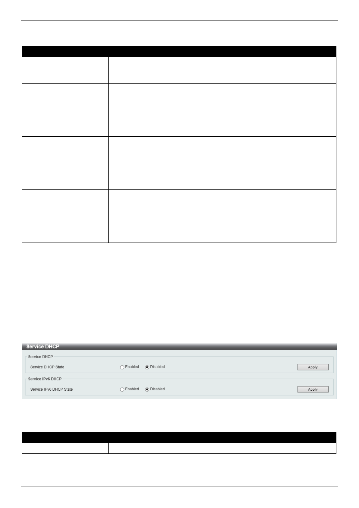
DGS-1520 Series Gigabit Ethernet Smart Managed Switch Web UI Reference Guide
54
The fields that can be configured are described below:
Parameter Description
Web Session Timeout
Enter the web session timeout value here. The range is from 60 to 36000 seconds.
By default, this value is 180 seconds.
Select the Default option to use the default value.
Console Session Timeout
Enter the console session timeout value here. The range is from 0 to 1439
minutes. Enter 0 to disable the timeout. By default, this value is 3 minutes.
Select the Default option to use the default value.
Outgoing Console Session
Timeout
Enter the outgoing console session timeout value here. The range is from 0 to
1439 minutes. Enter 0 to disable the timeout. By default, this value is 0.
Select the Default option to use the default value.
Telnet Session Timeout
Enter the Telnet session timeout value here. The range is from 0 to 1439 minutes.
Enter 0 to disable the timeout. By default, this value is 3 minutes.
Select the Default option to use the default value.
Outgoing Telnet Session
Timeout
Enter the outgoing Telnet session timeout value here. The range is from 0 to 1439
minutes. Enter 0 to disable the timeout. By default, this value is 0.
Select the Default option to use the default value.
SSH Session Timeout
Enter the SSH session timeout value here. The range is from 0 to 1439 minutes.
Enter 0 to disable the timeout. By default, this value is 3 minutes.
Select the Default option to use the default value.
Outgoing SSH Session
Timeout
Enter the outgoing SSH session timeout value here. The range is from 0 to 1439
minutes. Enter 0 to disable the timeout. By default, this value is 0.
Select the Default option to use the default value.
Click the Apply button to accept the changes made.
DHCP
Service DHCP
This window is used to display and configure the DHCP service on the Switch.
To view the following window, click Management > DHCP > Service DHCP, as shown below:
Figure 4-27 Service DHCP Window
The fields that can be configured in Service DHCP are described below:
Parameter Description
Service DHCP State
Select this option to enable or disable the DHCP service.
Click the Apply button to accept the changes made.
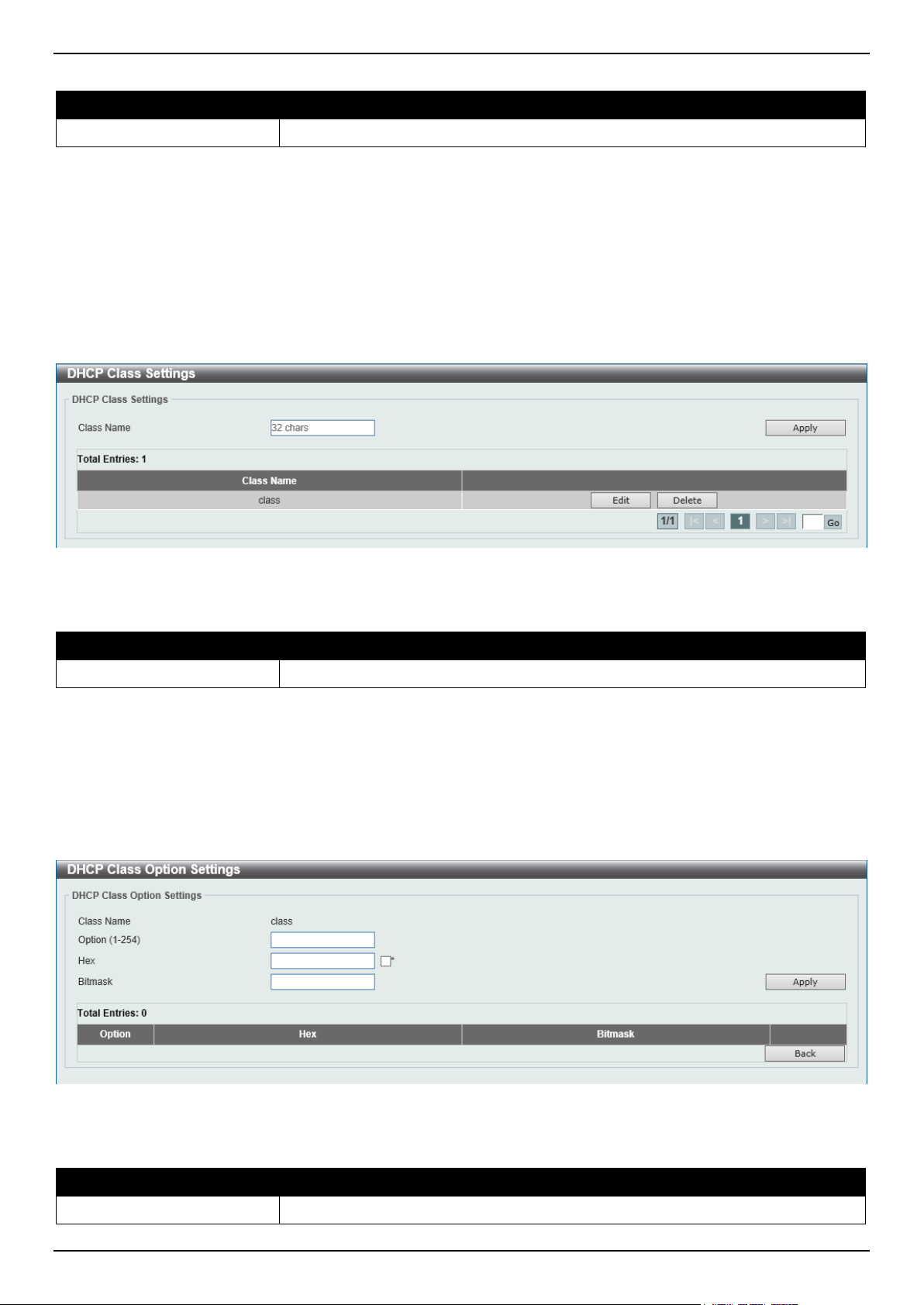
DGS-1520 Series Gigabit Ethernet Smart Managed Switch Web UI Reference Guide
55
The fields that can be configured in Service IPv6 DHCP are described below:
Parameter Description
Service IPv6 DHCP State
Select this option to enable or disable the IPv6 DHCP service.
Click the Apply button to accept the changes made.
DHCP Class Settings
This window is used to display and configure the DHCP class and the DHCP option-matching pattern for the DHCP
class.
To view the following window, click Management > DHCP > DHCP Class Settings, as shown below:
Figure 4-28 DHCP Class Settings Window
The fields that can be configured are described below:
Parameter Description
Class Name
Enter the DHCP class name with a maximum of 32 characters.
Click the Apply button to accept the changes made.
Click the Edit button to modify the DHCP option-matching pattern for the corresponding DCHP class.
Click the Delete button to remove the specified entry.
Enter a page number and click the Go button to navigate to a specific page when multiple pages exist.
After clicking the Edit button, the following window will appear.
Figure 4-29 DHCP Class Settings (Edit) Window
The fields that can be configured are described below:
Parameter Description
Option
Enter the DHCP option number. The range is from 1 to 254.
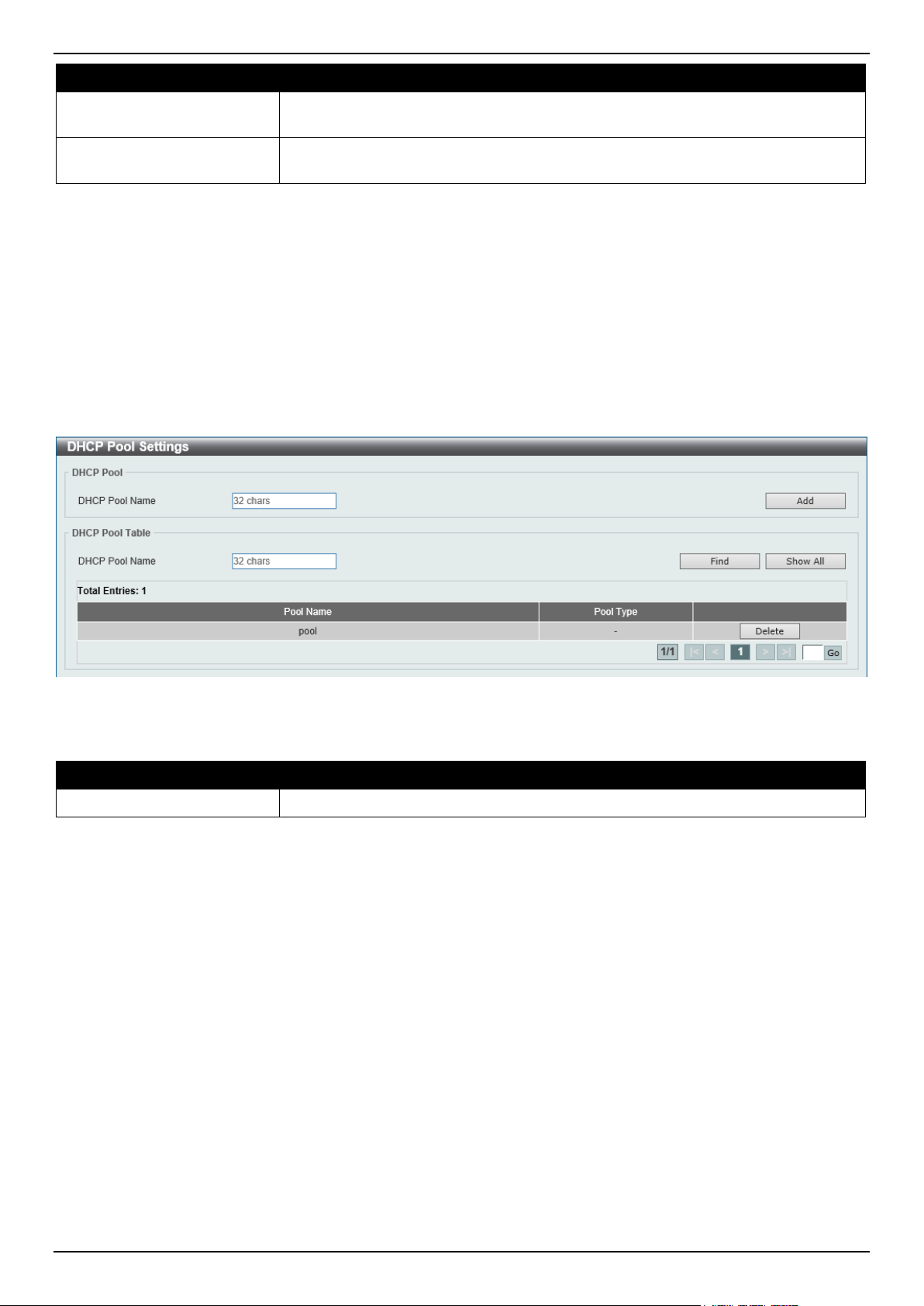
DGS-1520 Series Gigabit Ethernet Smart Managed Switch Web UI Reference Guide
56
Parameter Description
Hex Enter the hex pattern of the specified DHCP option. Tick the * check box not to
match the remaining bits of the option.
Bitmask
Enter the hex bit mask for masking of the pattern. The masked pattern bits will be
matched. If not specified, all bits entered in the Hex field will be checked.
Click the Apply button to accept the changes made.
Click the Delete button to remove the specified entry.
Click the Back button to return to the previous window.
DHCP Pool Settings
This window is used to display and configure the DHCP pool settings
To view the following window, click Management > DHCP > DHCP Pool Settings, as shown below:
Figure 4-30 DHCP Pool Settings Window
The fields that can be configured are described below:
Parameter Description
DHCP Pool Name
Enter the name of the DHCP pool here. This can be up to 32 characters long.
Click the Add button to add a new DHCP pool.
Click the Find button to find and display the DHCP pool in the table.
Click the Show All button to display all the DHCP pools in the table.
Click the Delete button to delete the specified DHCP pool.
Enter a page number and click the Go button to navigate to a specific page when multiple pages exist.
DHCP Server
The Dynamic Host Configuration Protocol (DHCP) allows the Switch to designate IP addresses, subnet masks, default
gateways and other IP parameters to devices that request this information. This occurs when a DHCP enabled device
is booted on or attached to the locally attached network. This device is known as the DHCP client and when enabled,
it will emit query messages on the network before any IP parameters are set. When the DHCP server receives this
request, it will allocate an IP address to the client. The DHCP client may be then utilize the IP address allocated by the
DHCP server as its local configuration.
The user can configure many DHCP related parameters that it will utilize on its locally attached network, to control and
limit the IP settings of clients desiring an automatic IP configuration, such as the lease time of the allocated IP
address, the range of IP addresses that will be allowed in its DHCP pool, the ability to exclude various IP addresses
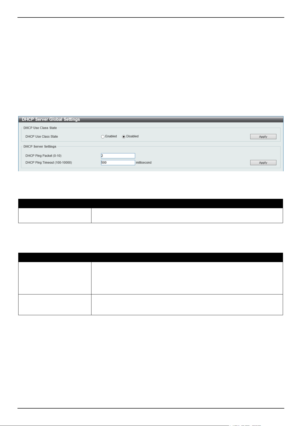
DGS-1520 Series Gigabit Ethernet Smart Managed Switch Web UI Reference Guide
57
within the range so as not to make identical entries on its network, or to assign the IP address of an important device
(such as a DNS server or the IP address of the default route) to another device on the network.
Users also have the ability to bind IP addresses within the DHCP pool to specific MAC addresses in order to assign
the same IP addresses to important devices.
DHCP Server Global Settings
This window is used to display and configure the global DHCP server parameters.
To view the following window, click Management > DHCP > DHCP Server > DHCP Server Global Settings, as
shown below:
Figure 4-31 DHCP Server Global Settings Window
The fields that can be configured in DHCP Use Class State are described below:
Parameter Description
DHCP Use Class State
Select to enable or disable the DHCP Use Class State here. When enabled, the
DHCP server will use DHCP classes for address allocation.
Click the Apply button to accept the changes made.
The fields that can be configured in DHCP Server Settings are described below:
Parameter Description
DHCP Ping Packet
Enter the number of ping packets that the Switch will send out on the network
containing the IP address to be allotted. If the ping request is not returned, the IP
address is considered unique to the local network and then allotted to the
requesting client. A value of 0 means there is no ping test. The range is from 0 to
10. By default, this value is 2.
DHCP Ping Timeout
Enter the amount of time the DHCP server must wait before timing out a ping
packet. The range is from 100 to 10000 milliseconds. By default, this value is 500
milliseconds.
Click the Apply button to accept the changes made.
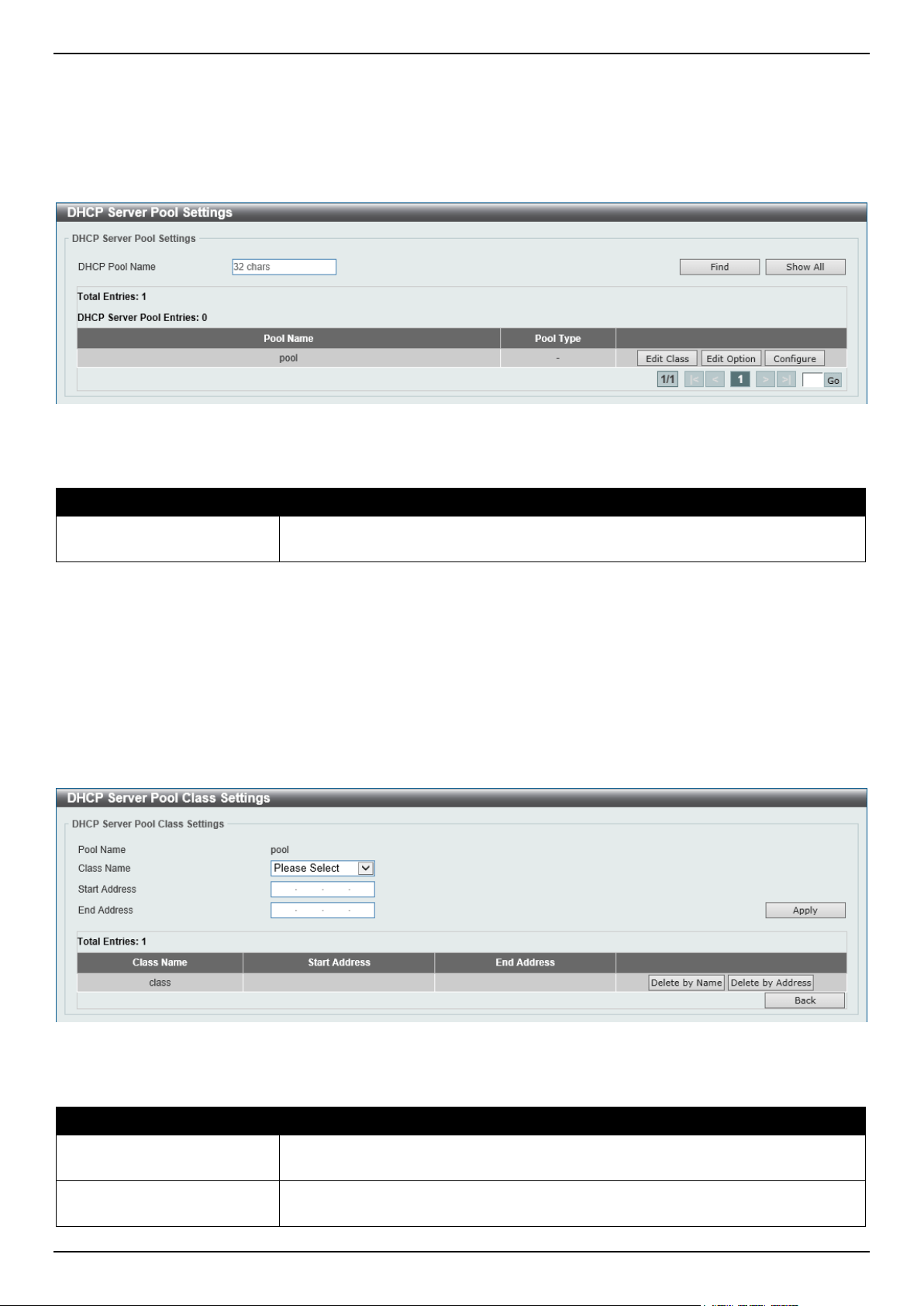
DGS-1520 Series Gigabit Ethernet Smart Managed Switch Web UI Reference Guide
58
DHCP Server Pool Settings
This window is used to display and configure the DHCP server pool settings.
To view the following window, click Management > DHCP > DHCP Server > DHCP Server Pool Settings, as shown
below:
Figure 4-32 DHCP Server Pool Settings Window
The fields that can be configured are described below:
Parameter Description
DHCP Pool Name
Enter the DHCP server pool name here. This name can be up to 32 characters
long.
Click the Find button to find and display the DHCP pool in the table.
Click the Show All button to display all the DHCP pools in the table.
Click the Edit Class button to configure the DHCP class.
Click the Edit Option button to configure the DHCP server pool option settings.
Click the Configure button to configure the DHCP server pool settings.
Enter a page number and click the Go button to navigate to a specific page when multiple pages exist.
After clicking the Edit Class button, the following page will appear.
Figure 4-33 DHCP Server Pool Class Settings Window
The fields that can be configured are described below:
Parameter Description
Class Name
Select an existing DHCP class name here that will be associated with this DHCP
pool.
Start Address
Enter the starting IPv4 address that will be associated with the DHCP class in the
DHCP pool here.
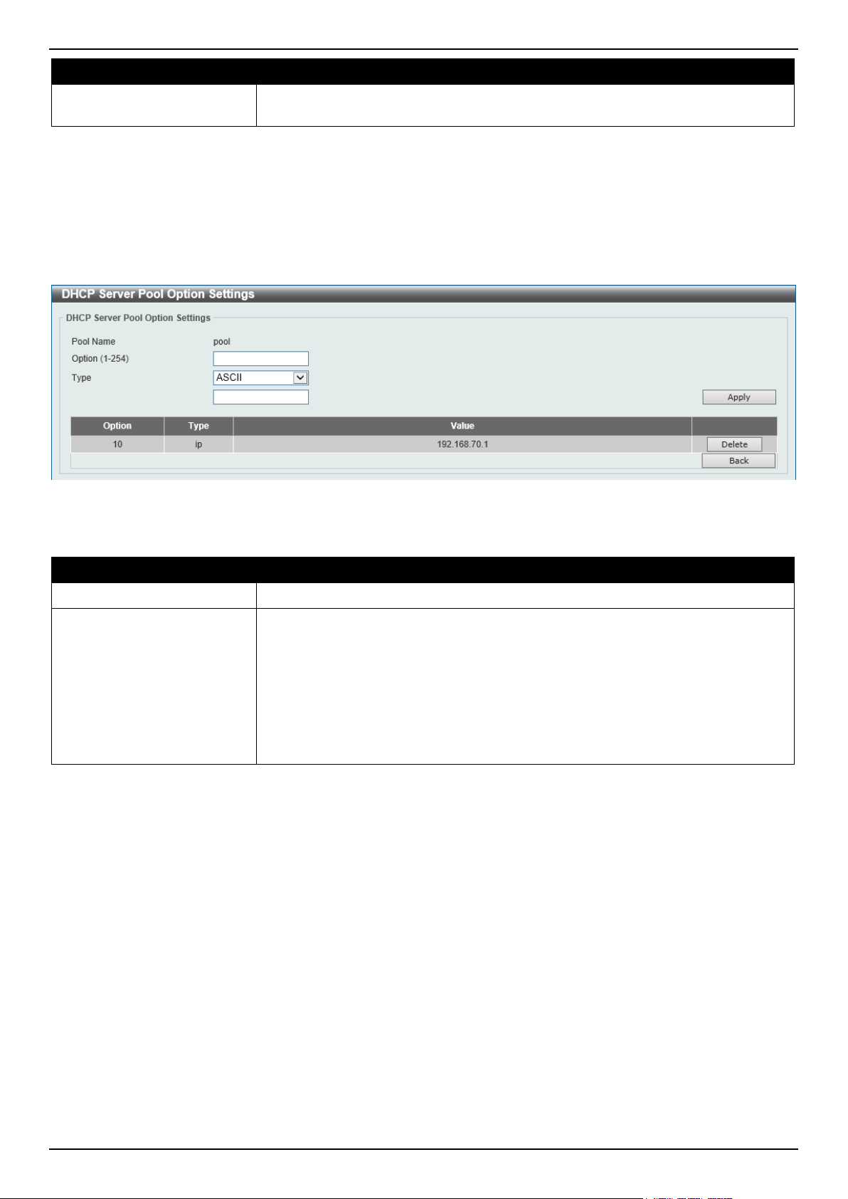
DGS-1520 Series Gigabit Ethernet Smart Managed Switch Web UI Reference Guide
59
Parameter Description
End Address
Enter the ending IPv4 address that will be associated with the DHCP class in the
DHCP pool here.
Click the Apply button to accept the changes made.
Click the Delete by Name button to remove the DHCP class association by name.
Click the Delete by Address button to remove the DHCP class association by address.
Click the Back button to return to the previous window.
After clicking the Edit Option button, the following page will appear.
Figure 4-34 DHCP Server Pool Option Settings Window
The fields that can be configured are described below:
Parameter Description
Option
Enter the DHCP option number here. The range is from 1 to 254.
Type
Select the DHCP option type here. Options to choose from are:
• ASCII - Enter the ASCII string in the space provided. This string can be up
to 255 characters long.
• Hex - Enter the hexadecimal string in the space provided. This string can be
up to 254 characters long. Select the None option to specify a zero-length
hexadecimal string.
• IP - Enter the IPv4 address(es) in the space(s) provided. Up to 8 IPv4
addresses can be entered.
Click the Apply button to accept the changes made.
Click the Delete button to remove the specified entry.
Click the Back button to return to the previous window.
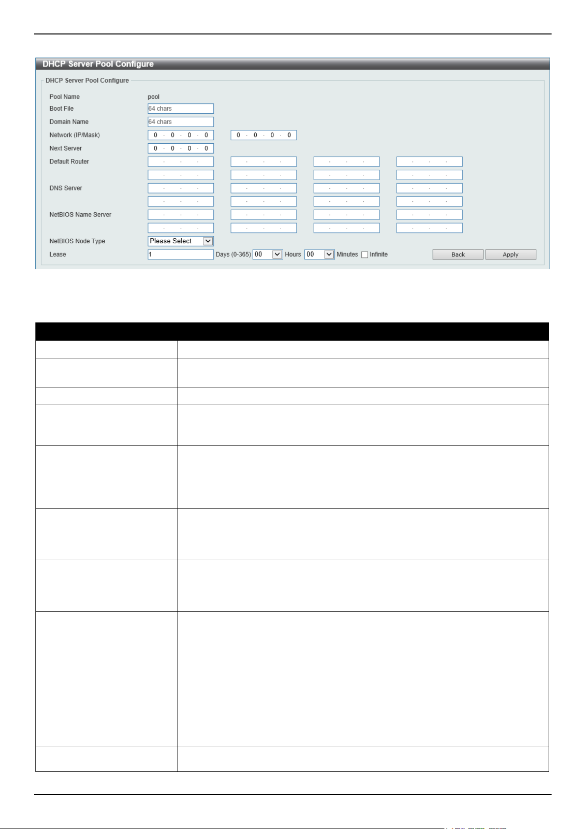
DGS-1520 Series Gigabit Ethernet Smart Managed Switch Web UI Reference Guide
60
After clicking the Configure button, the following page will appear.
Figure 4-35 DHCP Server Pool Configure Window
The fields that can be configured are described below:
Parameter Description
Boot File
Enter the boot file name here. This can be up to 64 characters long.
Domain Name
Enter the domain name for the DHCP client here. This can be up to 64 characters
long.
Network (IP/Mask)
Enter the network IPv4 address and subnet mask for the DHCP client here.
Next Server
Enter the next server IPv4 address here. The boot image file is stored on this
server and can be retrieved by DHCP clients using this IP address. The server is
typically a TFTP server. Only one next server IP address can be specified.
Default Router
Enter the IPv4 address of the default router for the DHCP client here. Up to 8 IPv4
address can be entered here. The IP address of the router should be on the same
subnet as the client's subnet. Routers are listed in the order of preference. If
default routers are already configured, the default routers configured later will be
added to the default interface list.
DNS Server
Enter the IPv4 address to be used by the DHCP client as the DNS server here. Up
to 8 IPv4 address can be entered here. Servers are listed in the order of
preference. If DNS servers are already configured, the DNS servers configured
later will be added to the DNS server list.
NetBIOS Name Server
Enter the WINS name server IPv4 address for the DHCP client here. Up to 8 IPv4
address can be entered here. Servers are listed in the order of preference. If name
servers are already configured, the name server configured later will be added to
the default interface list.
NetBIOS Node Type
Select the NetBIOS node type for Microsoft DHCP clients here. The node type
determines the method that NetBIOS uses to register and resolve names. Options
to choose from are:
• Broadcast - The Broadcast system uses broadcasts.
• Peer To Peer - The Peer To Peer (p-node) system uses only point-to-point
name queries to a name server (WINS).
• Mixed - The Mixed (m-node) system broadcasts first, and then queries the
name server.
• Hybrid - The Hybrid (h-node) system queries the name server first, and
then broadcasts. The Hybrid type is recommended.
Lease
Enter and select the lease time for an IPv4 address that is assigned from the
address pool here. Enter the Days in the range from 0 to 365. Select the Hours
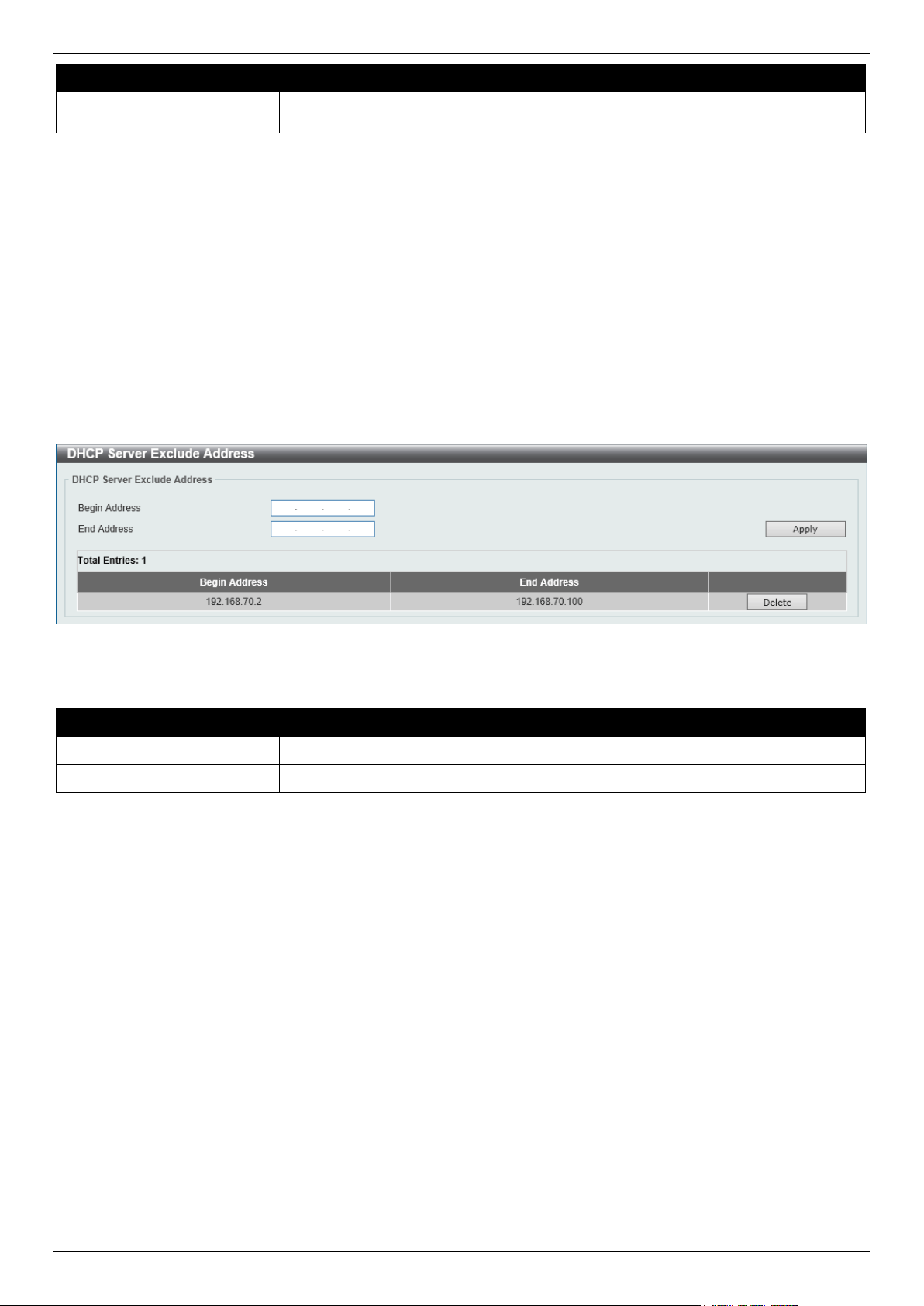
DGS-1520 Series Gigabit Ethernet Smart Managed Switch Web UI Reference Guide
61
Parameter Description
and Minutes from the drop-down menus. Alternatively, the Infinite option can be
selected to specify that the lease time is unlimited.
Click the Apply button to accept the changes made.
Click the Back button to return to the previous window.
DHCP Server Exclude Address
This window is used to view and exclude a range of IPv4 addresses from being allocated to the DHCP client. The
DHCP server automatically allocates addresses in DHCP address pools to DHCP clients. All the addresses except the
interface's IP address on the router and the excluded address(es) specified here are available for allocation. Multiple
ranges of addresses can be excluded. To remove a range of excluded addresses, administrators must specify the
exact range of addresses previously configured.
To view the following window, click Management > DHCP > DHCP Server > DHCP Server Exclude Address, as
shown below:
Figure 4-36 DHCP Server Exclude Address Window
The fields that can be configured are described below:
Parameter Description
Begin Address
Enter the first IPv4 address of a range of addresses to be excluded here.
End Address
Enter the last IPv4 address of a range of addresses to be excluded here.
Click the Apply button to accept the changes made.
Click the Delete button to remove the specified entry.
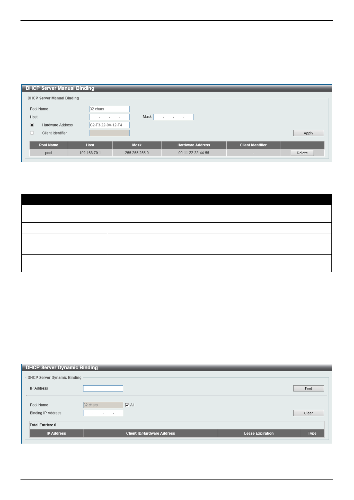
DGS-1520 Series Gigabit Ethernet Smart Managed Switch Web UI Reference Guide
62
DHCP Server Manual Binding
This window is used to display and configure the DHCP server manual binding settings. With a manual binding entry,
the IP address can be bound with a client-identifier or bound with the hardware address of the host.
To view the following window, click Management > DHCP > DHCP Server > DHCP Server Manual Binding, as
shown below:
Figure 4-37 DHCP Server Manual Binding Window
The fields that can be configured are described below:
Parameter Description
Pool Name
Enter the DHCP server pool name here. This name can be up to 32 characters
long.
Host
Enter the DHCP host IPv4 address here.
Mask
Enter the DHCP host network subnet mask here.
Hardware Address
Enter the DHCP host MAC address here.
Client Identifier
Enter the DHCP host identifier in hexadecimal notation here. The client identifier is
formatted by the media type and the MAC address.
Click the Apply button to accept the changes made.
Click the Delete button to remove the specified entry.
DHCP Server Dynamic Binding
This window is used to view and clear the DHCP server dynamic binding entries.
To view the following window, click Management > DHCP > DHCP Server > DHCP Server Dynamic Binding, as
shown below:
Figure 4-38 DHCP Server Dynamic Binding Window
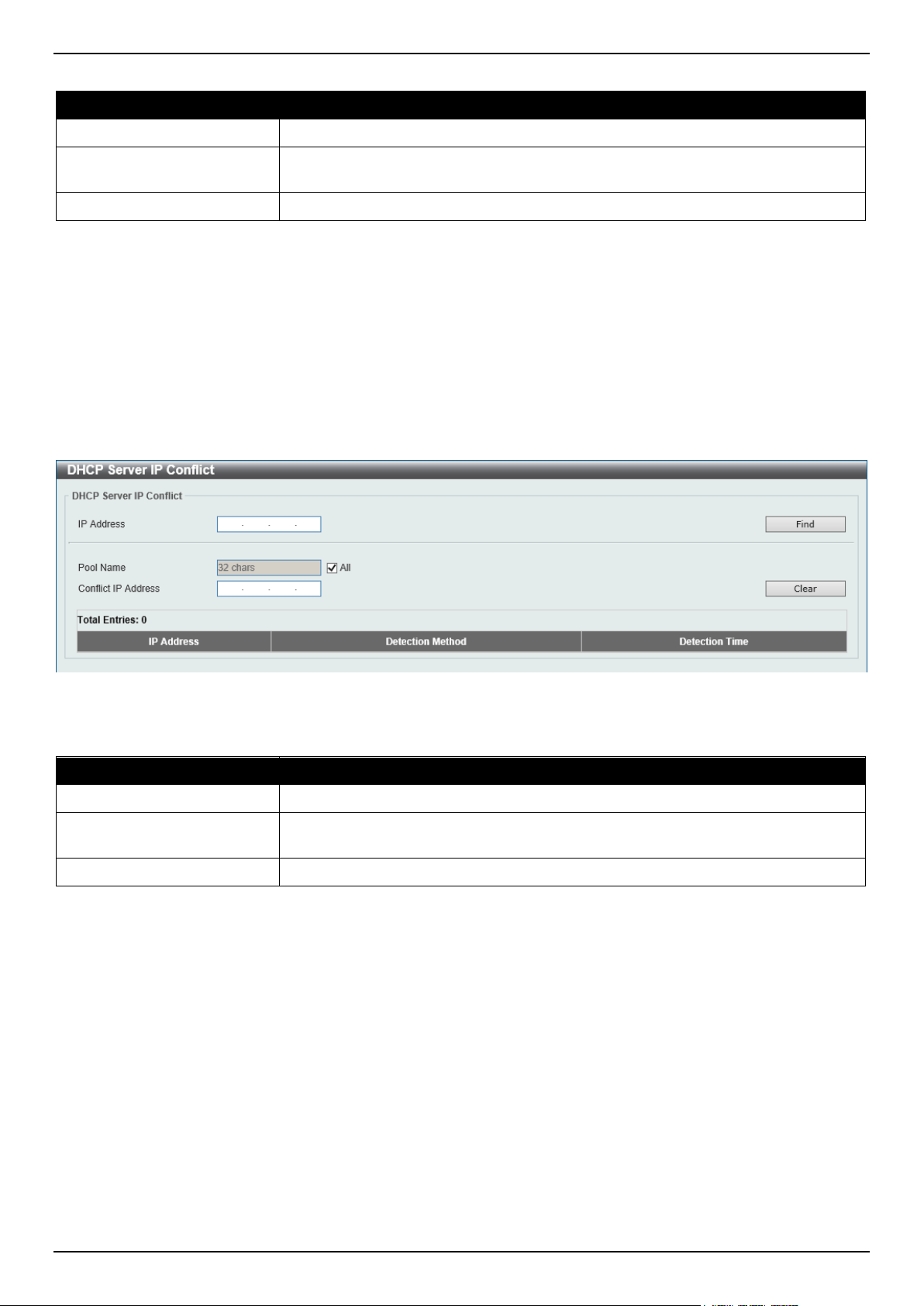
DGS-1520 Series Gigabit Ethernet Smart Managed Switch Web UI Reference Guide
63
The fields that can be configured are described below:
Parameter Description
IP Address
Enter the binding entry IPv4 address here.
Pool Name
Enter the DHCP server pool name here. This name can be up to 32 characters
long. Select the All option to clear the binding entries for all pools.
Binding IP Address
Enter the binding IP address here.
Click the Find button to locate a specific entry based on the information entered.
Click the Clear button to clear the entries based on the information specified.
DHCP Server IP Conflict
This window is used to view and clear the DHCP conflict entries from the DHCP server database.
To view the following window, click Management > DHCP > DHCP Server > DHCP Server IP Conflict, as shown
below:
Figure 4-39 DHCP Server IP Conflict Window
The fields that can be configured are described below:
Parameter Description
IP Address
Enter the IPv4 address of the conflict entry to be located or cleared.
Pool Name
Enter the DHCP server pool name here. This name can be up to 32 characters
long. Select the All option to clear the conflict entries for all pools.
Conflict IP Address
Enter the conflict IP address here.
Click the Find button to locate a specific entry based on the information entered.
Click the Clear button to clear the entries based on the information specified.
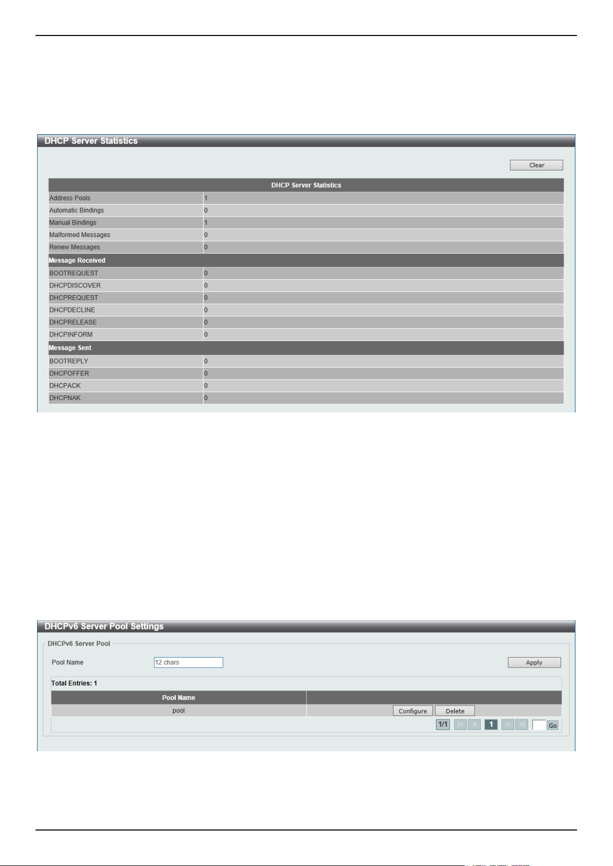
DGS-1520 Series Gigabit Ethernet Smart Managed Switch Web UI Reference Guide
64
DHCP Server Statistic
This window is used to display DHCP server statistics.
To view the following window, click Management > DHCP > DHCP Server > DHCP Server Statistic, as shown
below:
Figure 4-40 DHCP Server Statistic Window
Click the Clear button to clear the statistics information displayed here.
DHCPv6 Server
DHCPv6 Server Pool Settings
This window is used to display and configure the DHCPv6 server pool settings.
To view the following window, click Management > DHCP > DHCPv6 Server > DHCPv6 Server Pool Settings, as
shown below:
Figure 4-41 DHCPv6 Server Pool Settings Window
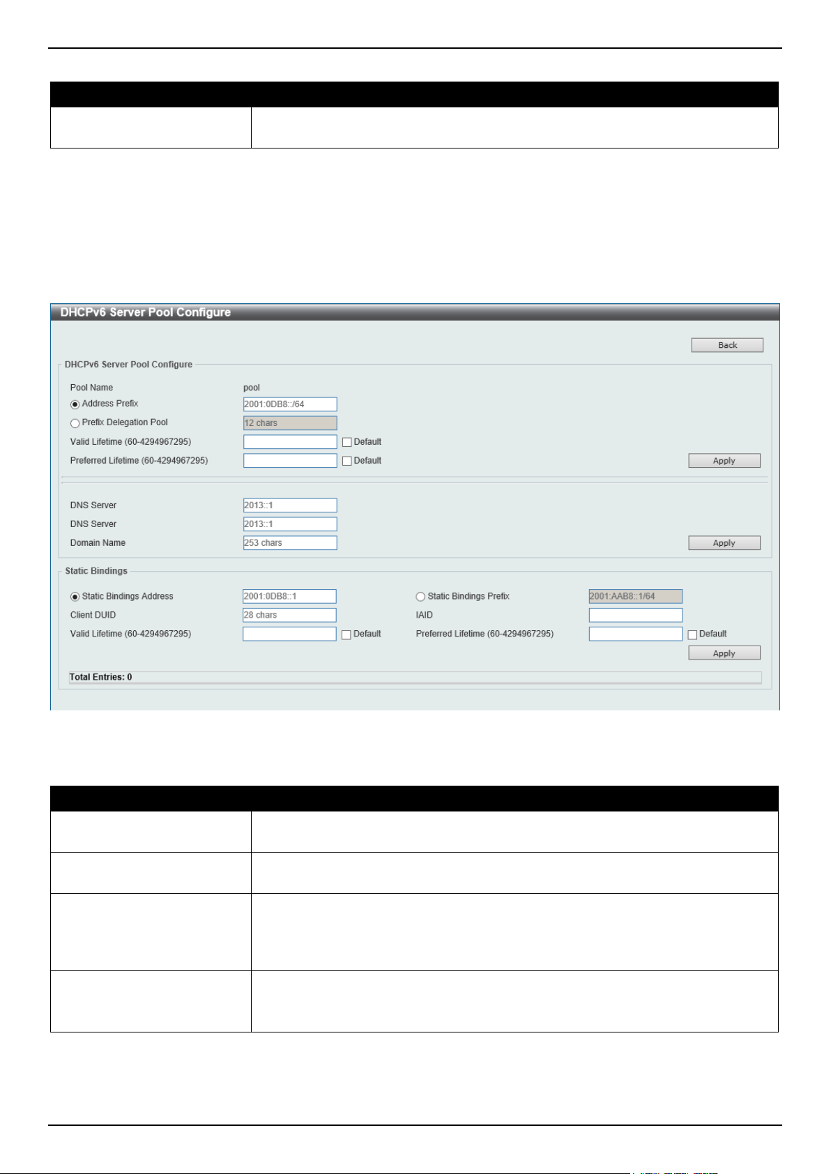
DGS-1520 Series Gigabit Ethernet Smart Managed Switch Web UI Reference Guide
65
The fields that can be configured are described below:
Parameter Description
Pool Name
Enter the DHCPv6 server pool name here. This name can be up to 12 characters
long.
Click the Apply button to accept the changes made.
Click the Configure button to configure the DHCPv6 server pool settings.
Click the Delete button to remove the specified entry.
Enter a page number and click the Go button to navigate to a specific page when multiple pages exist.
After clicking the Configure button, the following page will appear.
Figure 4-42 DHCPv6 Server Pool Configure Window
The fields that can be configured in DHCPv6 Server Pool Configure are described below:
Parameter Description
Address Prefix
Select and enter the DHCPv6 server pool IPv6 network address and prefix length
here. For example, 2015::0/64.
Prefix Delegation Pool
Select and enter the DHCPv6 server pool prefix delegation name here. This name
can be up to 12 characters long.
Valid Lifetime
Enter the valid lifetime value here. The valid lifetime should be greater than
preferred lifetime. The range is from 60 to 4294967295 seconds. By default, this
value is 2592000 seconds (30 days).
Select Default to use the default value.
Preferred Lifetime
Enter the preferred lifetime value here. The range is from 60 to 4294967295
seconds. By default, this value is 604800 seconds (7 days).
Select Default to use the default value.
Click the Apply button to accept the changes made.
Click the Back button to return to the previous window.
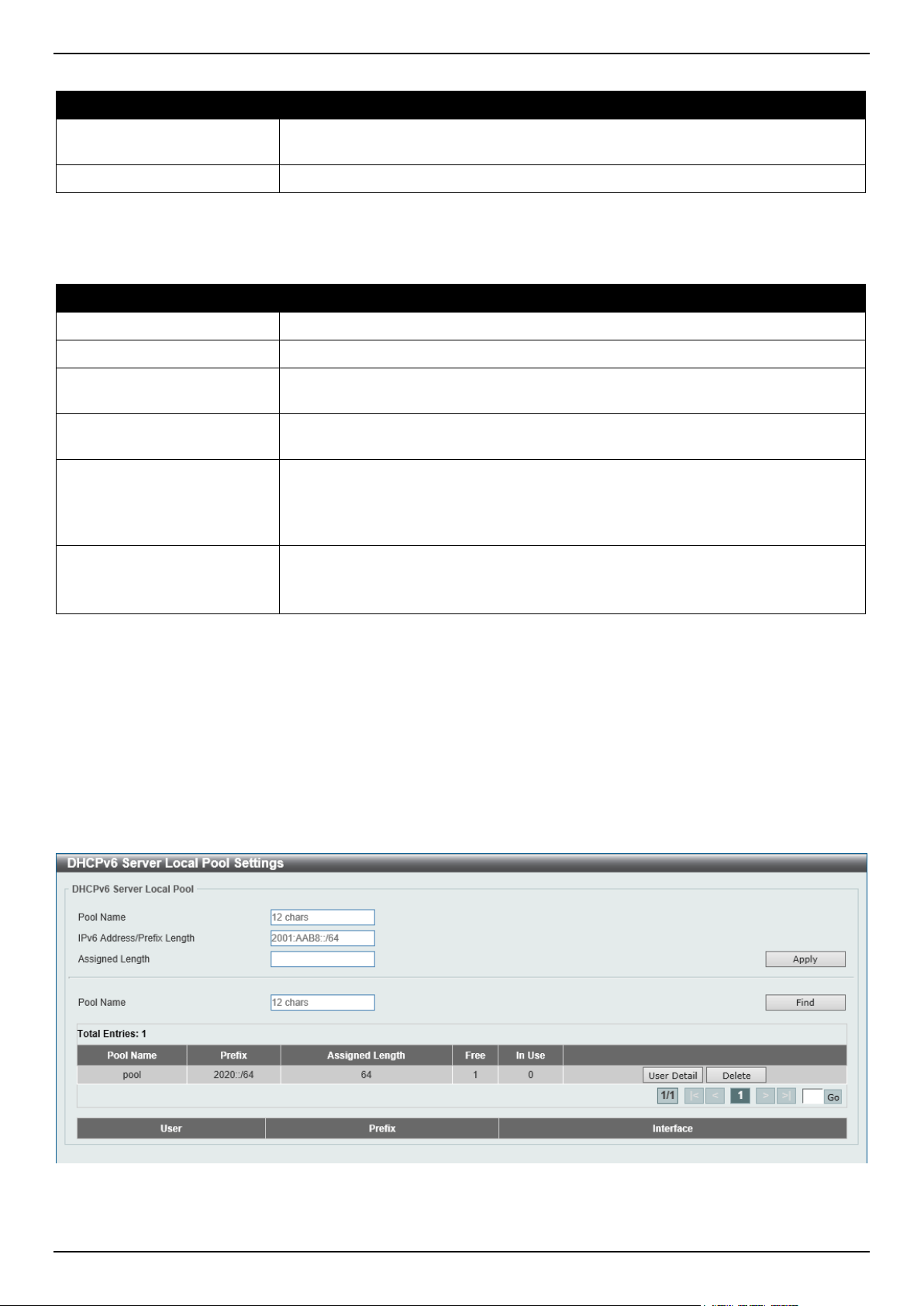
DGS-1520 Series Gigabit Ethernet Smart Managed Switch Web UI Reference Guide
66
The fields that can be configured in Configure DNS/Domain Name are described below:
Parameter Description
DNS Server
Enter the DNS server IPv6 address to be assigned to requesting DHCPv6 clients
here. Up to two DNS server can be configured.
Domain Name
Enter the domain name to be assigned to requesting DHCPv6 clients here.
Click the Apply button to accept the changes made.
The fields that can be configured in Static Bindings are described below:
Parameter Description
Static Bindings Address
Enter the static binding IPv6 address assign to the specific client here.
Static Bindings Prefix
Enter the static binding IPv6 network address and prefix length here.
Client DUID
Enter the client DHCP Unique Identifier (DUID) here. This string can be up to 28
characters long.
IAID
Enter the Identity Association Identifier (IAID) here. The IAID here uniquely
identifies a collection of non-temporary addresses (IANA) assigned on the client.
Valid Lifetime
Enter the valid lifetime value here. The valid lifetime should be greater than the
preferred lifetime. The range is from 60 to 4294967295 seconds. By default, this
value is 2592000 seconds (30 days).
Select Default to use the default value.
Preferred Lifetime
Enter the preferred lifetime value here. The range is from 60 to 4294967295
seconds. By default, this value is 604800 seconds (7 days).
Select Default to use the default value.
Click the Apply button to accept the changes made.
Click the Delete button to remove the specified entry.
DHCPv6 Server Local Pool Settings
This window is used to display and configure the DHCPv6 server local pool settings.
To view the following window, click Management > DHCP > DHCPv6 Server > DHCPv6 Server Local Pool
Settings, as shown below:
Figure 4-43 DHCPv6 Server Local Pool Settings Window
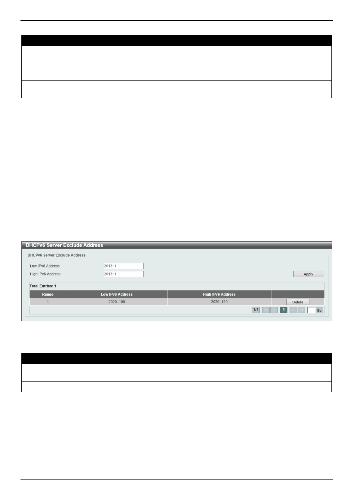
DGS-1520 Series Gigabit Ethernet Smart Managed Switch Web UI Reference Guide
67
The fields that can be configured are described below:
Parameter Description
Pool Name
Enter the DHCPv6 server pool name here. This name can be up to 12 characters
long.
IPv6 Address / Prefix
Length
Enter the IPv6 prefix address and prefix length of the local pool here.
Assigned Length
Enter the prefix length to be delegated to the user from the pool here. The value of
the assigned length cannot be less than the value of the prefix length.
Click the Apply button to accept the changes made.
Click the Find button to locate a specific entry based on the information entered.
Click the User Detail button to view the user information displayed in the lower table.
Click the Delete button to remove the specified entry.
Enter a page number and click the Go button to navigate to a specific page when multiple pages exist.
DHCPv6 Server Exclude Address
This window is used to specify IPv6 addresses that a DHCPv6 server should not assign to DHCPv6 clients. The
DHCPv6 server assumes that all addresses (excluding the Switch's IPv6 address) can be assigned to clients. Use this
window to exclude a single IPv6 address or a range of IPv6 addresses. The excluded addresses are only applied to
the pool(s) for address assignment.
To view the following window, click Management > DHCP > DHCPv6 Server > DHCPv6 Server Exclude Address,
as shown below:
Figure 4-44 DHCPv6 Server Exclude Address Window
The fields that can be configured are described below:
Parameter Description
Low IPv6 Address
Enter the excluded IPv6 address or first IPv6 address in the excluded address
range here.
High IPv6 Address
Enter the last IPv6 address in the excluded address range here (optional).
Click the Apply button to accept the changes made.
Click the Delete button to remove the specified entry.
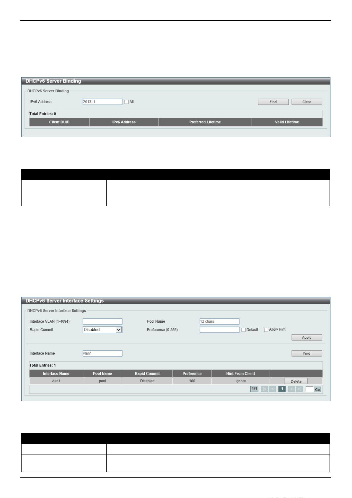
DGS-1520 Series Gigabit Ethernet Smart Managed Switch Web UI Reference Guide
68
DHCPv6 Server Binding
This window is used to view and clear the DHCPv6 server binding entries.
To view the following window, click Management > DHCP > DHCPv6 Server > DHCPv6 Server Binding, as shown
below:
Figure 4-45 DHCPv6 Server Binding Window
The fields that can be configured are described below:
Parameter Description
IPv6 Address
Enter the binding entry IPv6 address to be displayed or cleared here.
Select All to display or clear all DHCPv6 client prefix bindings in or from the
binding table.
Click the Find button to locate a specific entry based on the information entered.
Click the Clear button to clear the entries based on the information specified.
DHCPv6 Server Interface Settings
This window is used to display and configure the DHCPv6 server interface settings.
To view the following window, click Management > DHCP > DHCPv6 Server > DHCPv6 Server Interface Settings,
as shown below:
Figure 4-46 DHCPv6 Server Interface Settings Window
The fields that can be configured are described below:
Parameter Description
Interface VLAN
Enter the interface VLAN ID here. The range is from 1 to 4094.
Pool Name
Enter the DHCPv6 server pool name here. This name can be up to 12 characters
long.
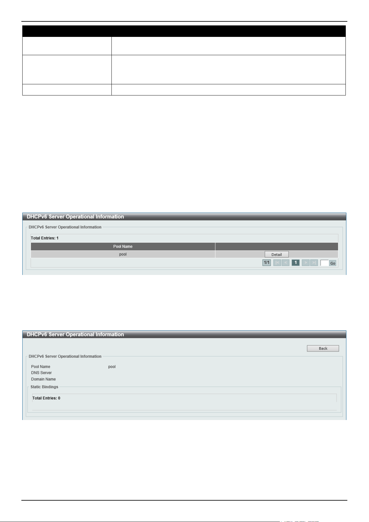
DGS-1520 Series Gigabit Ethernet Smart Managed Switch Web UI Reference Guide
69
Parameter Description
Rapid Commit
Select to enable or disable two-message exchange here. By default, two-message
exchange is not allowed.
Preference
Enter the preference value here. The range is from 0 to 255.
Select the Allow Hint option to allow hints.
Select Default to use the default value.
Interface Name
Enter the interface name here.
Click the Apply button to accept the changes made.
Click the Find button to locate a specific entry based on the information entered.
Click the Delete button to remove the specified entry.
Enter a page number and click the Go button to navigate to a specific page when multiple pages exist.
DHCPv6 Server Operational Information
This window is used to display the DHCPv6 server operational information.
To view the following window, click Management > DHCP > DHCPv6 Server > DHCPv6 Server Operational
Information, as shown below:
Figure 4-47 DHCPv6 Server Operational Information Window
Click the Detail button to view detailed DHCPv6 operational information.
After clicking the Detail button, the following window will appear.
Figure 4-48 DHCPv6 Server Operational Information (Detail) Window
Click the Back button to return to the previous window.
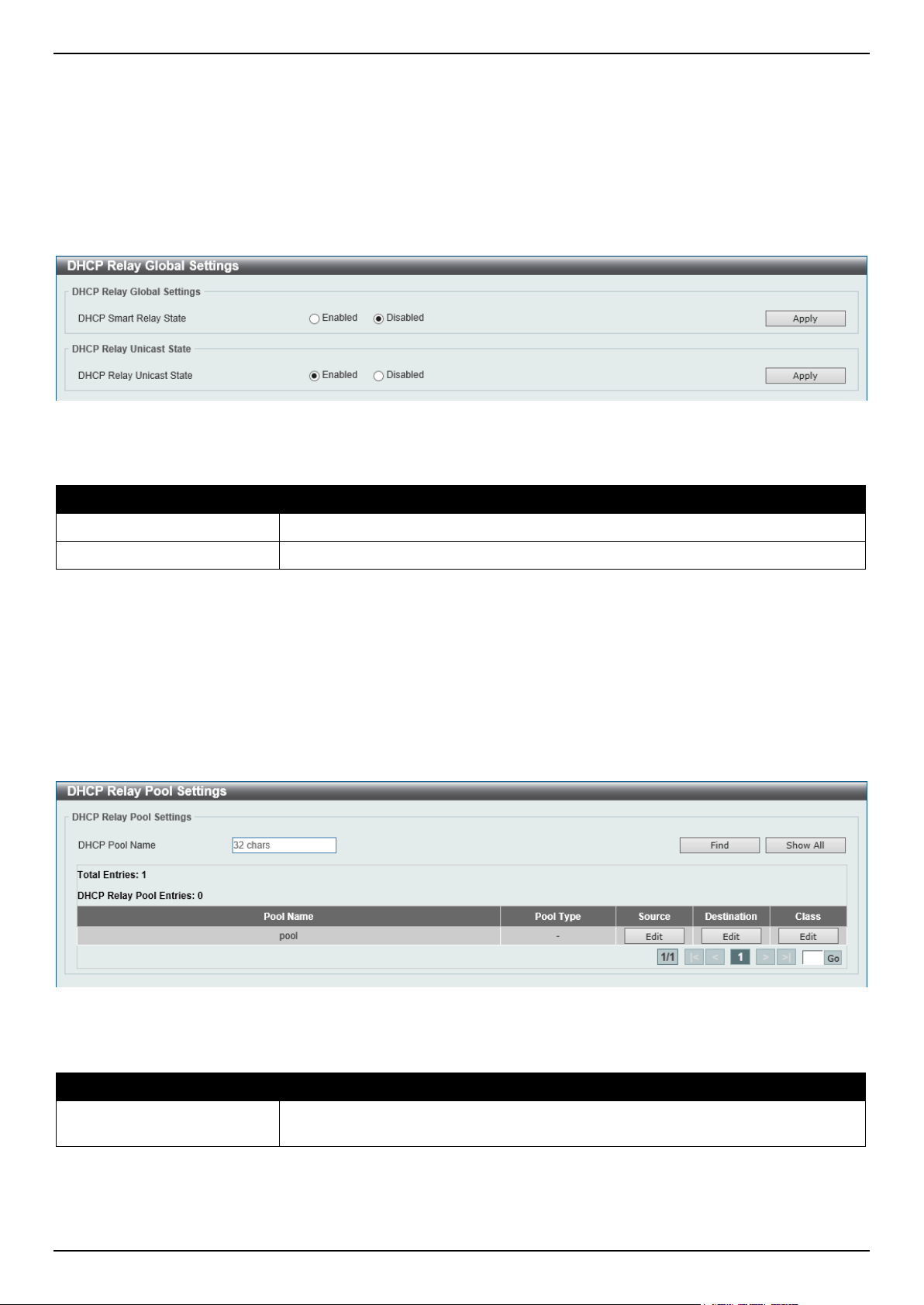
DGS-1520 Series Gigabit Ethernet Smart Managed Switch Web UI Reference Guide
70
DHCP Relay
DHCP Relay Global Settings
This window is used to display and configure the global DHCP relay settings.
To view the following window, click Management > DHCP > DHCP Relay > DHCP Relay Global Settings, as shown
below:
Figure 4-49 DHCP Relay Global Settings Window
The fields that can be configured are described below:
Parameter Description
DHCP Smart Relay State
Select to globally enable or disable the DHCP smart relay state here.
DHCP Relay Unicast State
Select to globally enable or disable the DHCP relay unicast state here.
Click the Apply button to accept the changes made.
DHCP Relay Pool Settings
This window is used to display and configure the DHCP relay pool on a DHCP relay agent.
To view the following window, click Management > DHCP > DHCP Relay > DHCP Relay Pool Settings, as shown
below:
Figure 4-50 DHCP Relay Pool Settings Window
The fields that can be configured are described below:
Parameter Description
DHCP Pool Name
Enter the name of the DHCP pool here. This name can be up to 32 characters
long.
Click the Find button to find and display the DHCP pool in the table.
Click the Show All button to display all the DHCP pools in the table.
Click the Edit button to modify the corresponding information of the specific DHCP pool.
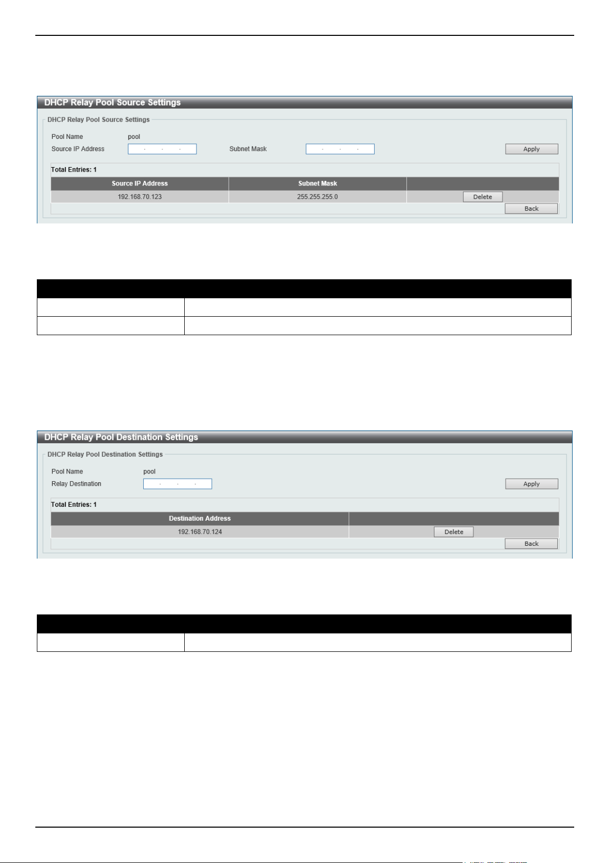
DGS-1520 Series Gigabit Ethernet Smart Managed Switch Web UI Reference Guide
71
Enter a page number and click the Go button to navigate to a specific page when multiple pages exist.
After clicking the Edit button under Source, the following window will appear.
Figure 4-51 DHCP Relay Pool Source Settings Window
The fields that can be configured are described below:
Parameter Description
Source IP Address
Enter the source subnet of client packets.
Subnet Mask
Enter the network mask of the source subnet.
Click the Apply button to accept the changes made.
Click the Delete button to remove the specified entry.
Click the Back button to return to the previous window.
After clicking the Edit button under Destination, the following window will appear.
Figure 4-52 DHCP Relay Pool Destination Settings Window
The fields that can be configured are described below:
Parameter Description
Relay Destination
Enter the relay destination DHCP server IP address.
Click the Apply button to accept the changes made.
Click the Delete button to remove the specified entry.
Click the Back button to return to the previous window.
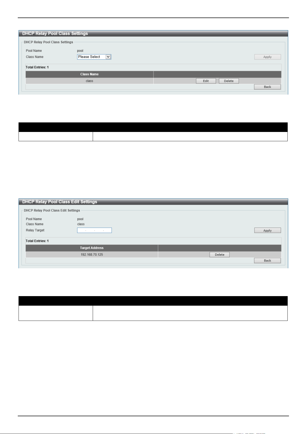
DGS-1520 Series Gigabit Ethernet Smart Managed Switch Web UI Reference Guide
72
After clicking the Edit button under Class, the following window will appear.
Figure 4-53 DHCP Relay Pool Class Settings Window
The fields that can be configured are described below:
Parameter Description
Class Name
Select the DHCP class name.
Click the Apply button to accept the changes made.
Click the Edit button to edit more information.
Click the Delete button to remove the specified entry.
Click the Back button to return to the previous window.
After clicking the Edit button, the following window will appear.
Figure 4-54 DHCP Relay Pool Class Edit Settings Window
The fields that can be configured are described below:
Parameter Description
Relay Target
Enter the DHCP relay target for relaying packets that matches the value pattern of
the option defined in the DHCP class.
Click the Apply button to accept the changes made.
Click the Delete button to remove the specified entry.
Click the Back button to return to the previous window.
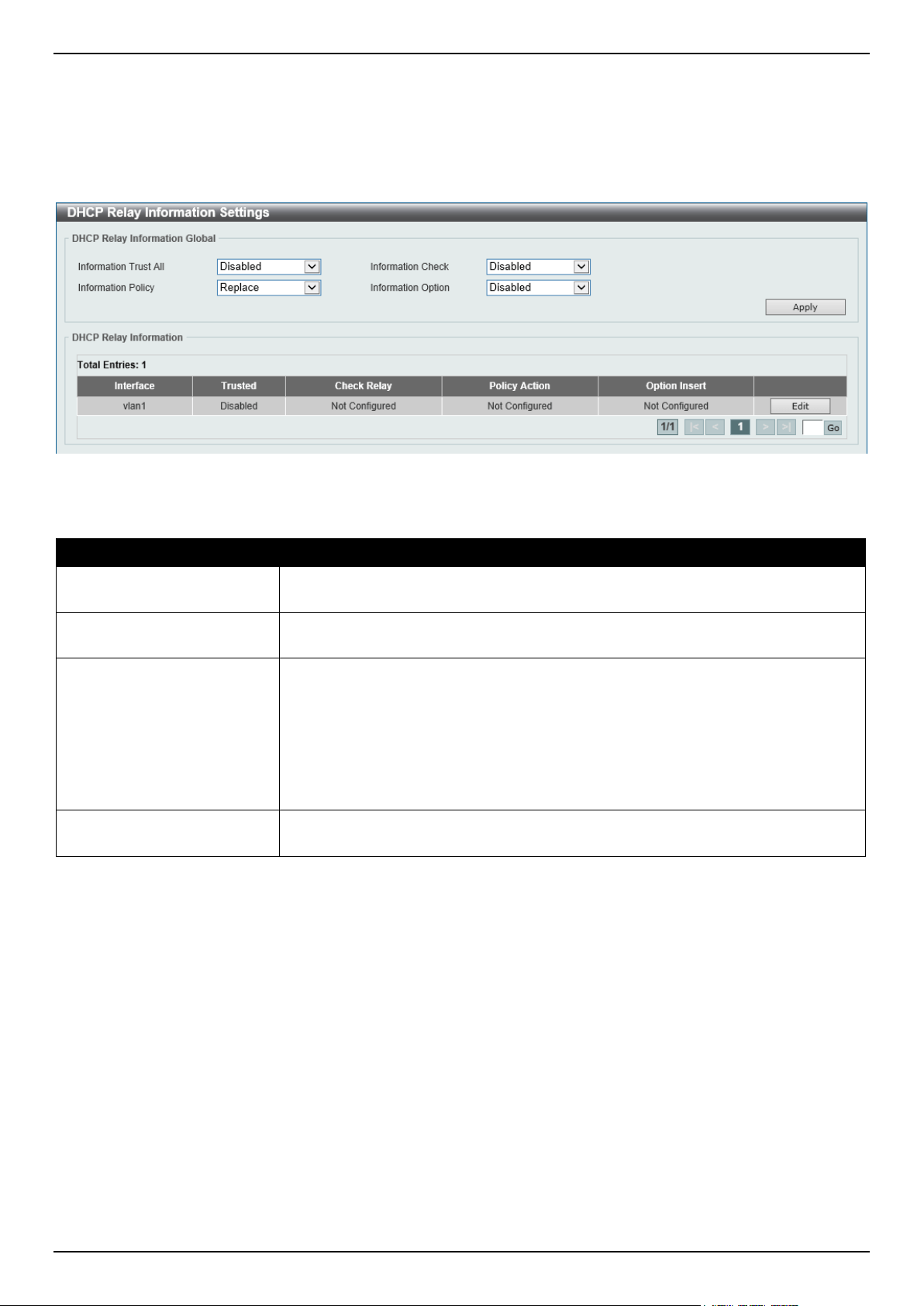
DGS-1520 Series Gigabit Ethernet Smart Managed Switch Web UI Reference Guide
73
DHCP Relay Information Settings
This window is used to display and configure the DHCP relay information.
To view the following window, click Management > DHCP > DHCP Relay > DHCP Relay Information Settings, as
shown below:
Figure 4-55 DHCP Relay Information Settings Window
The fields that can be configured are described below:
Parameter Description
Information Trust All
Select this option to enable or disable the DHCP relay agent to trust the IP DHCP
relay information for all interfaces.
Information Check
Select this option to enable or disable the DHCP relay agent to validate and
remove the relay agent information option in the received DHCP reply packet.
Information Policy
Select the Option 82 re-forwarding policy for the DHCP relay agent. Options to
choose from are:
• Keep - Select to keep the packet that already has the relay option. The
packet is left unchanged and directly relayed to the DHCP server.
• Drop - Select to discard the packet that already has the relay option.
• Replace - Select to replace the packet that already has the relay option.
The packet will be replaced with a new option.
Information Option
Select this option to enable or disable the insertion of relay agent information
(Option 82) during the relay of DHCP request packets.
Click the Apply button to accept the changes made.
Click the Edit button to modify the corresponding interface.
Enter a page number and click the Go button to navigate to a specific page when multiple pages exist.
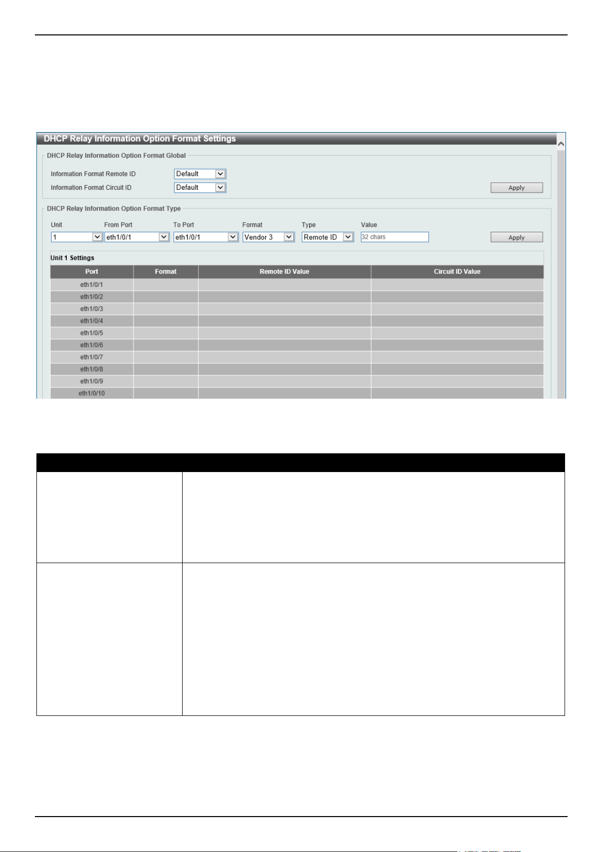
DGS-1520 Series Gigabit Ethernet Smart Managed Switch Web UI Reference Guide
74
DHCP Relay Information Option Format Settings
This window is used to display and configure the DHCP information format.
To view the following window, click Management > DHCP > DHCP Relay > DHCP Relay Information Option
Format Settings, as shown below:
Figure 4-56 DHCP Relay Information Option Format Settings Window
The fields that can be configured in DHCP Relay Information Option Format Global are described below:
Parameter Description
Information Format Remote
ID
Select the DHCP information remote ID sub-option. Options to choose from are:
• Default - Select to use the Switch's system MAC address as the remote ID.
• User Define - Select to use a user-defined remote ID. Enter the user-
defined string with the maximum of 32 characters in the text box.
• Vendor2 - Select to use vendor 2 as the remote ID.
• Vendor3 - Select to use vendor 3 as the remote ID.
Information Format Circuit
ID
Select the DHCP information circuit ID sub-option. Options to choose from are:
• Default - Select to use the default circuit ID sub-option.
• User Define - Select to use a user-defined circuit ID. Enter the user-defined
string with the maximum of 32 characters in the text box.
• Vendor1 - Select to use vendor 1 as the circuit ID.
• Vendor2 - Select to use vendor 2 as the circuit ID.
• Vendor3 - Select to use vendor 3 as the circuit ID.
• Vendor4 - Select to use vendor 4 as the circuit ID.
• Vendor5 - Select to use vendor 5 as the circuit ID.
• Vendor6 - Select to use vendor 6 as the circuit ID.
Click the Apply button to accept the changes made.
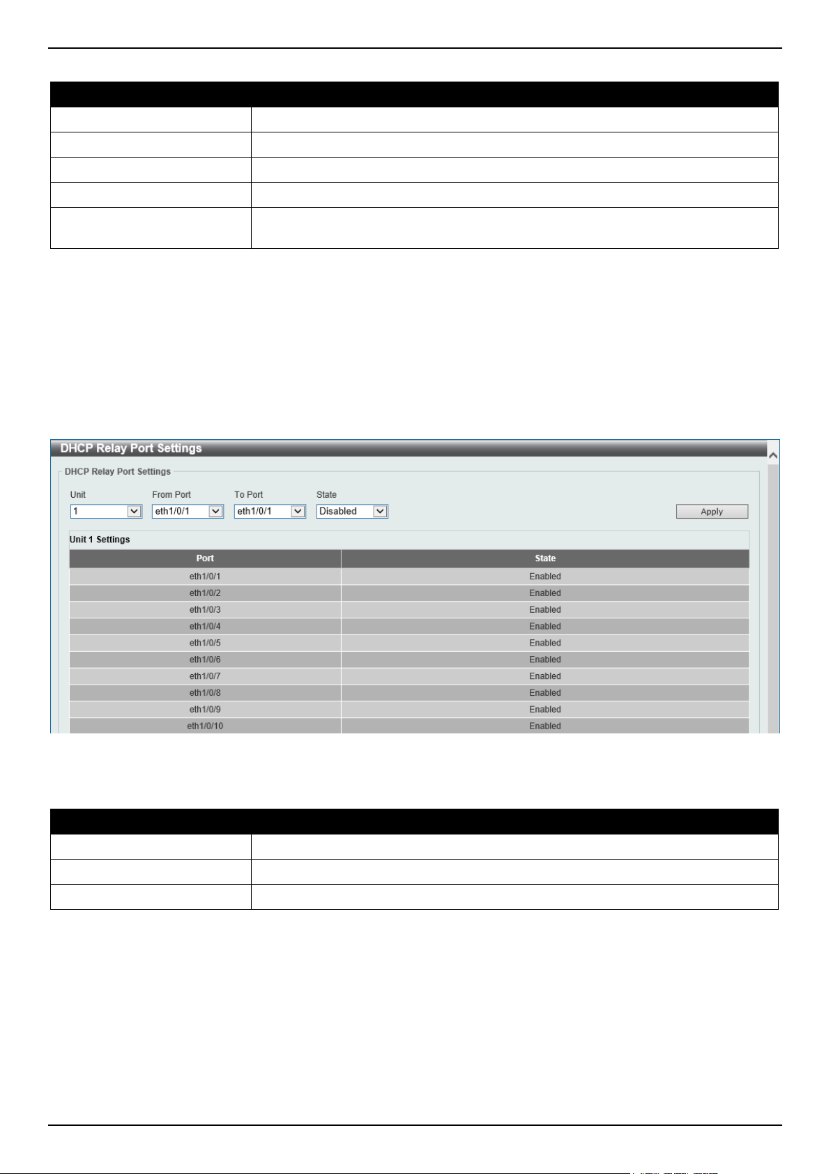
DGS-1520 Series Gigabit Ethernet Smart Managed Switch Web UI Reference Guide
75
The fields that can be configured in DHCP Relay Information Option Format Global are described below:
Parameter Description
Unit
Select the Switch unit that will be used for this configuration here.
From Port - To Port
Select the range of ports that will be used for this configuration here.
Format
Specifies that the user-defined Vendor 3 string format will be used.
Type Select to use the Remote ID type or Circuit ID type here.
Value
Enter the vendor-defined string for Option 82 information in the remote/circuit ID
sub-option here. This string can be up to 32 characters long.
Click the Apply button to accept the changes made.
DHCP Relay Port Settings
This window is used to display and configure the DHCP relay port settings.
To view the following window, click Management > DHCP > DHCP Relay > DHCP Relay Port Settings, as shown
below:
Figure 4-57 DHCP Relay Port Settings Window
The fields that can be configured are described below:
Parameter Description
Unit
Select the Switch unit that will be used for this configuration here.
From Port - To Port
Select the range of ports that will be used for this configuration here.
State
Select to enable or disable the DHCP Relay feature on the specified port(s).
Click the Apply button to accept the changes made.
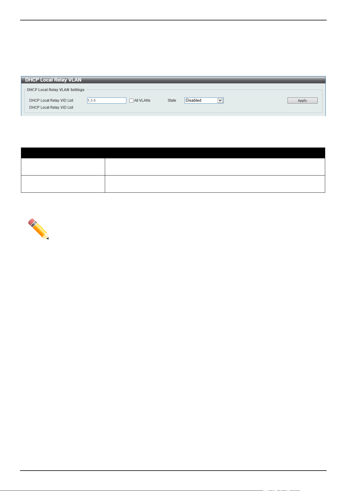
DGS-1520 Series Gigabit Ethernet Smart Managed Switch Web UI Reference Guide
76
DHCP Local Relay VLAN
This window is used to display and configure local relay on a VLAN or a group of VLANs.
To view the following window, click Management > DHCP > DHCP Relay > DHCP Local Relay VLAN, as shown
below:
Figure 4-58 DHCP Local Relay VLAN Window
The fields that can be configured are described below:
Parameter Description
DHCP Local Relay VID List Enter the VLAN ID for DHCP local relay. Tick the All VLANs check box to select
all VLANs.
State
Select this option to enable or disable the DHCP local relay on the specific
VLAN(s).
Click the Apply button to accept the changes made.
NOTE: When the state of the DHCP relay port is disabled, the port will not relay or locally relay
received DHCP packets.
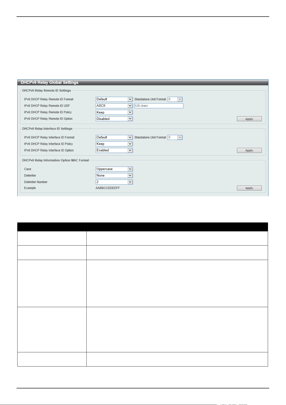
DGS-1520 Series Gigabit Ethernet Smart Managed Switch Web UI Reference Guide
77
DHCPv6 Relay
DHCPv6 Relay Global Settings
This window is used to display and configure the DHCPv6 Relay remote ID settings.
To view the following window, click Management > DHCP > DHCPv6 Relay > DHCPv6 Relay Global Settings, as
shown below:
Figure 4-59 DHCPv6 Relay Global Settings Window
The fields that can be configured in DHCPv6 Relay Remote ID Settings are described below:
Parameter Description
IPv6 DHCP Relay Remote
ID Format
Select the IPv6 DHCP Relay remote ID format that will be used here. Options to
choose from are Default, CID with User Define, User Define, and Expert UDF.
Standalone Unit Format After selecting the Expert UDF option, select the standalone unit format here.
Options to choose from are 0 and 1.
IPv6 DHCP Relay Remote
ID UDF
Select to choose the User Define Field (UDF) for the remote ID. Options to choose
from are:
• None - Specifies to keep the UDF empty for the remote ID.
• ASCII - Select to enter the ASCII string with a maximum of 128 characters
in the text box.
• HEX - Select to enter the hexadecimal string with a maximum of 256
characters in the text box.
IPv6 DHCP Relay Remote
ID Policy
Select to choose Option 37 forwarding policy for the DHCPv6 relay agent. Options
to choose from are:
• Keep - Select that the DHCPv6 request packet that already has the relay
agent Remote-ID option is left unchanged and directly relayed to the
DHCPv6 server.
• Drop - Select to discard the packet that already has the relay agent
Remote-ID Option 37.
IPv6 DHCP Relay Remote
ID Option
Select this option to enable or disable the insertion of the relay agent remote ID
Option 37 during the relay of DHCP for IPv6 request packets.
Click the Apply button to accept the changes made.

DGS-1520 Series Gigabit Ethernet Smart Managed Switch Web UI Reference Guide
78
The fields that can be configured in DHCPv6 Relay Interface ID Settings are described below:
Parameter Description
IPv6 DHCP Relay Interface
ID Format
Select the IPv6 DHCP relay interface ID format that will be used here. Options to
choose from are Default, CID, Vendor1, and Expert UDF.
Standalone Unit Format After selecting the Expert UDF option, select the standalone unit format here.
Options to choose from are 0 and 1.
IPv6 DHCP Relay Interface
ID Policy
Select the Option 18 re-forwarding policy for the DHCPv6 relay agent here.
Options to choose from are:
• Keep - Specifies that the DHCPv6 request packets that already contain the
relay agent interface ID option are left unchanged and directly relay to the
DHCPv6 server.
• Drop - Specifies to discard the packets that already contain the relay agent
interface ID Option 18.
IPv6 DHCP Relay Interface
ID Option
Select to enable or disable the insertion of the relay agent interface ID Option 18
during the relay of DHCP for IPv6 request packets.
Click the Apply button to accept the changes made.
The fields that can be configured in DHCPv6 Relay Information Option MAC Format are described below:
Parameter Description
Case
Select the case that will be used here. Options to choose from are:
• Lowercase - Specifies that the MAC format will be lowercase.
For example, aa-bb-cc-dd-ee-ff.
• Uppercase - Specifies that the MAC format will be uppercase.
For example: AA-BB-CC-DD-EE-FF.
Delimiter
Select the delimiter that will be used here. Options to choose from are:
• Hyphen - Specifies that the MAC address format will contain hyphens.
For example, AA-BB-CC-DD-EE-FF.
• Colon - Specifies that the MAC address format will contain colons.
For example, AA:BB:CC:DD:EE:FF.
• Dot - Specifies that the MAC address format will contain dots.
For example, AA.BB.CC.DD.EE.FF.
• None - Specifies that the MAC address format will contain no delimiters.
For example, AABBCCDDEEFF.
Delimiter Number
Specifies the delimiter number that will be used in the MAC address format here.
Options to choose from are:
• 1 - Specifies to use a single delimiter.
For example, AABBCC.DDEEFF.
• 2 - Specifies to use two delimiters.
For example, AABB.CCDD.EEFF
• 5 - Specifies to use multiple delimiters.
For example, AA.BB.CC.DD.EE.FF
Click the Apply button to accept the changes made.
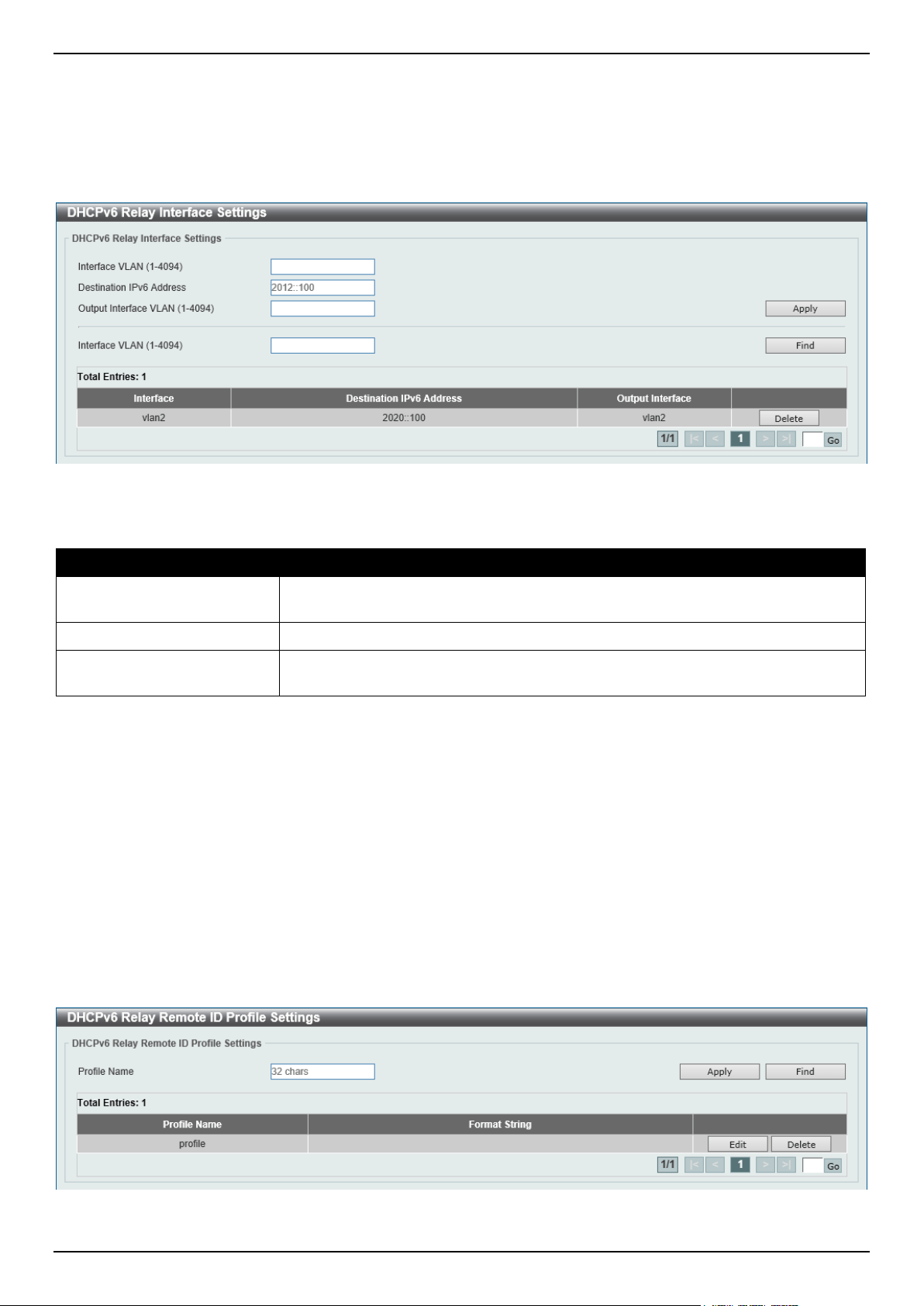
DGS-1520 Series Gigabit Ethernet Smart Managed Switch Web UI Reference Guide
79
DHCPv6 Relay Interface Settings
This window is used to display and configure the DHCPv6 relay interface settings.
To view the following window, click Management > DHCP > DHCPv6 Relay > DHCPv6 Relay Interface Settings, as
shown below:
Figure 4-60 DHCPv6 Relay Interface Settings Window
The fields that can be configured are described below:
Parameter Description
Interface VLAN
Enter the interface VLAN ID used in the DHCPv6 relay here. The range is from 1
to 4094.
Destination IPv6 Address
Enter the DHCPv6 relay destination address.
Output Interface VLAN
Enter the output interface VLAN ID for the relay destination here. The range is
from 1 to 4094.
Click the Apply button to accept the changes made.
Click the Find button to locate a specific entry based on the information entered.
Click the Delete button to remove the specified entry.
Enter a page number and click the Go button to navigate to a specific page when multiple pages exist.
DHCPv6 Relay Remote ID Profile Settings
This window is used to display and configure the DHCPv6 relay remote ID profile settings. This is used to create a
new profile for DHCPv6 relay Option 82.
To view the following window, click Management > DHCP > DHCPv6 Relay > DHCPv6 Relay Remote ID Profile
Settings, as shown below:
Figure 4-61 DHCPv6 Relay Remote ID Profile Settings Window

DGS-1520 Series Gigabit Ethernet Smart Managed Switch Web UI Reference Guide
80
The fields that can be configured are described below:
Parameter Description
Profile Name
Enter the profile name here. This string can be up to 32 characters long.
Format String After clicking the Edit button, enter the Expert UDF format type string for DHCPv6
Option 37 here. This string can be up to 251 characters long.
The following rules need to be considered:
• This string can be a hexadecimal value, an ASCII string, or any combination
of hexadecimal values and ASCII characters. An ASCII string needs to be
enclosed with quotation marks ("") like "Ethernet". Any ASCII characters
outside of the quotation marks will be interpreted as hexadecimal values.
• A formatted key string is a string that should be translated before being
encapsulated in the packet. A formatted key string can be contained both
ASCII strings and hexadecimal values. For example, "%" +"$"+"1~32"+
"keyword"+":":
o % - Indicates that the string that follows this character is a formatted
key string.
o "$" or "0" - (Optional) Indicates a fill indicator. This option specifies
how to fill the formatted key string to meet the length option. This
option can be either "$" or "0", and cannot be specified as both at the
same time.
"$" - Indicates to fill the leading space (0x20).
"0" - Indicates to fill the leading 0. By default, this option is
used.
o 1~32 - (Optional) Indicates a length option. This specifies how many
characters or bytes the translated key string should occupy. If the
actual length of the translated key string is less than the length
specified by this option, a fill indicator will be used to fill it. Otherwise,
this length option and fill indicator will be ignored and the actual
string will be used directly.
o keyword - Indicates that the keyword will be translated based on the
actual value of the system. The following keyword definitions
specifies that a command will be refused if an unknown or
unsupported keyword is detected:
devtype - The model name of the device. Only an ASCII
string is allowed.
sysname - Indicates the System name of the Switch. Only an
ASCII string is allowed.
ifdescr - Derived from ifDescr (IF-MIB). Only an ASCII string
is allowed.
portmac - Indicates the MAC address of a port. This can be
either an ASCII string or a hexadecimal value. When in the
format of an ASCII string, the MAC address format can be
customized using special CLI commands. When in the format
of a hexadecimal value, the MAC address will be
encapsulated in order in hexadecimal.
sysmac - Indicates the system MAC address. This can be
either an ASCII string or a hexadecimal value. In the ASCII
string format, the MAC address format can be customized
using special CLI commands. In the hexadecimal format, the
MAC address will be encapsulated in order in hexadecimal.
unit - Indicates the unit ID. This can be either an ASCII string
or a hexadecimal value. For a standalone device, the unit ID is
0.
module - Indicates the module ID number. This can be either
an ASCII string or a hexadecimal value.
port - Indicates the local port number. This can be either an
ASCII string or a hexadecimal value.
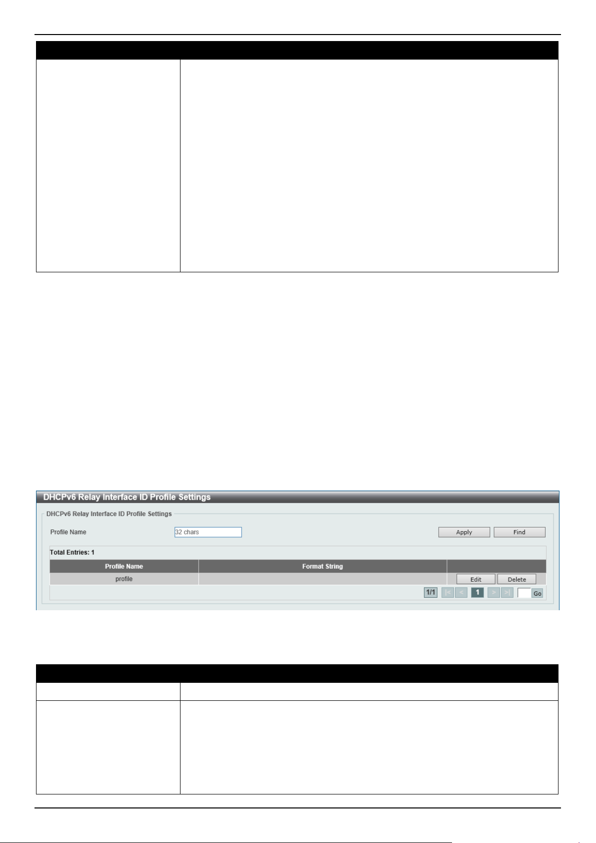
DGS-1520 Series Gigabit Ethernet Smart Managed Switch Web UI Reference Guide
81
Parameter Description
svlan - Indicates the outer VLAN ID. This can be either an
ASCII string or a hexadecimal value.
cvlan - Indicates the inner VLAN ID. This can be either an
ASCII string or a hexadecimal value.
o : - Indicates the end of the formatted key sting. If a formatted key
string is the last parameter of the command, its ending character (":")
can be ignored. The space (0x20) between "%" and ":" will be
ignored. Other spaces will be encapsulated.
• ASCII strings can be any combination of formatted key strings and 0~9, a~z,
A~Z, !@#$%^&*()_+|-=\[]{};:'"/?.,<>`, and space characters. "\" is the escape
character. The special character after "\" is the character itself, for example,
"\%" is "%" itself, not the start indicator of a formatted key string. Spaces not
in the formatted key string will also be encapsulated.
• Hexadecimal values can be any combination of formatted key strings and
0~9, A~F, a~f, and space characters. The formatted key strings only support
keywords that support hexadecimal values. Spaces not in the formatted key
string will be ignored.
Click the Apply button to accept the changes made.
Click the Find button to locate a specific entry based on the information entered.
Click the Edit button to re-configure the specific entry.
Click the Delete button to remove the specific entry.
Enter a page number and click the Go button to navigate to a specific page when multiple pages exist.
DHCPv6 Relay Interface ID Profile Settings
This window is used to display and configure the DHCPv6 relay interface ID profile settings. This is used to create a
new profile for the DHCPv6 relay Option 82.
To view the following window, click Management > DHCP > DHCPv6 Relay > DHCPv6 Relay Interface ID Profile
Settings, as shown below:
Figure 4-62 DHCPv6 Relay Interface ID Profile Settings Window
The fields that can be configured are described below:
Parameter Description
Profile Name
Enter the profile name here. This string can be up to 32 characters long.
Format String After clicking the Edit button, enter the Option 18 format string here. This string
can be up to 251 characters long.
The following rules need to be considered:
• This string can be a hexadecimal value, an ASCII string, or any combination
of hexadecimal values and ASCII characters. An ASCII string needs to be
enclosed with quotation marks ("") like "Ethernet". Any ASCII characters
outside of the quotation marks will be interpreted as hexadecimal values.

DGS-1520 Series Gigabit Ethernet Smart Managed Switch Web UI Reference Guide
82
Parameter Description
• A formatted key string is a string that should be translated before being
encapsulated in the packet. A formatted key string can be contained both
ASCII strings and hexadecimal values. For example, "%" +"$"+"1~32"+
"keyword"+":":
o % - Indicates that the string that follows this character is a formatted
key string.
o "$" or "0" - (Optional) Indicates a fill indicator. This option specifies
how to fill the formatted key string to meet the length option. This
option can be either "$" or "0", and cannot be specified as both at the
same time.
"$" - Indicates to fill the leading space (0x20).
"0" - Indicates to fill the leading 0. By default, this option is
used.
o 1~32 - (Optional) Indicates a length option. This specifies how many
characters or bytes the translated key string should occupy. If the
actual length of the translated key string is less than the length
specified by this option, a fill indicator will be used to fill it. Otherwise,
this length option and fill indicator will be ignored and the actual
string will be used directly.
o keyword - Indicates that the keyword will be translated based on the
actual value of the system. The following keyword definitions
specifies that a command will be refused if an unknown or
unsupported keyword is detected:
devtype - The model name of the device. Only an ASCII
string is allowed.
sysname - Indicates the System name of the Switch. Only an
ASCII string is allowed.
ifdescr - Derived from ifDescr (IF-MIB). Only an ASCII string
is allowed.
portmac - Indicates the MAC address of a port. This can be
either an ASCII string or a hexadecimal value. When in the
format of an ASCII string, the MAC address format can be
customized using special CLI commands. When in the format
of a hexadecimal value, the MAC address will be
encapsulated in order in hexadecimal.
sysmac - Indicates the system MAC address. This can be
either an ASCII string or a hexadecimal value. In the ASCII
string format, the MAC address format can be customized
using special CLI commands. In the hexadecimal format, the
MAC address will be encapsulated in order in hexadecimal.
unit - Indicates the unit ID. This can be either an ASCII string
or a hexadecimal value. For a standalone device, the unit ID is
0.
module - Indicates the module ID number. This can be either
an ASCII string or a hexadecimal value.
port - Indicates the local port number. This can be either an
ASCII string or a hexadecimal value.
svlan - Indicates the outer VLAN ID. This can be either an
ASCII string or a hexadecimal value.
cvlan - Indicates the inner VLAN ID. This can be either an
ASCII string or a hexadecimal value.
o : - Indicates the end of the formatted key sting. If a formatted key
string is the last parameter of the command, its ending character (":")
can be ignored. The space (0x20) between "%" and ":" will be
ignored. Other spaces will be encapsulated.
• ASCII strings can be any combination of formatted key strings and 0~9, a~z,
A~Z, !@#$%^&*()_+|-=\[]{};:'"/?.,<>`, and space characters. "\" is the escape
character. The special character after "\" is the character itself, for example,
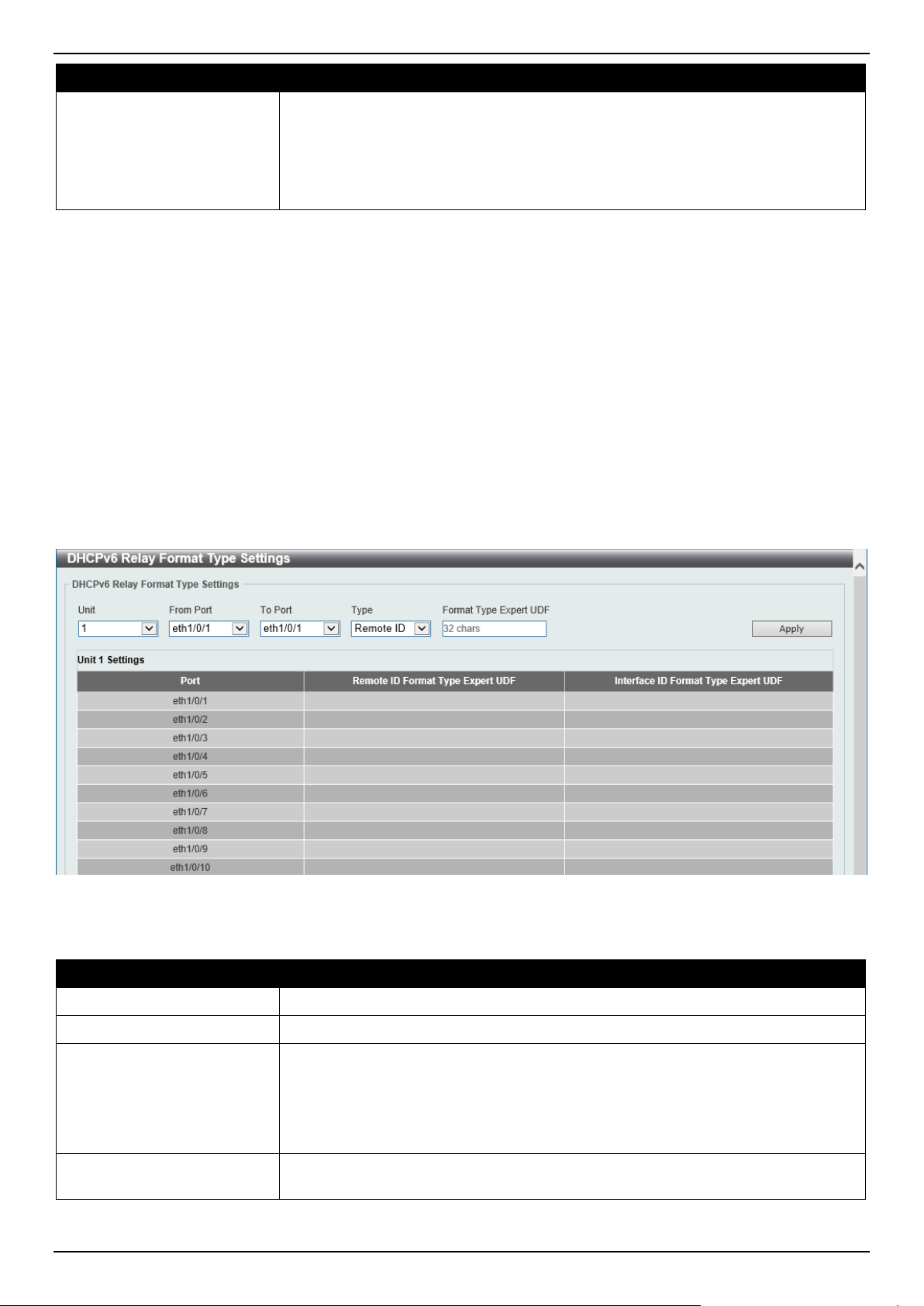
DGS-1520 Series Gigabit Ethernet Smart Managed Switch Web UI Reference Guide
83
Parameter Description
"\%" is "%" itself, not the start indicator of a formatted key string. Spaces not
in the formatted key string will also be encapsulated.
• Hexadecimal values can be any combination of formatted key strings and
0~9, A~F, a~f, and space characters. The formatted key strings only support
keywords that support hexadecimal values. Spaces not in the formatted key
string will be ignored.
Click the Apply button to accept the changes made.
Click the Find button to locate a specific entry based on the information entered.
Click the Edit button to re-configure the specific entry.
Click the Delete button to remove the specific entry.
Enter a page number and click the Go button to navigate to a specific page when multiple pages exist.
DHCPv6 Relay Format Type Settings
This window is used to display and configure the DHCPv6 relay format type settings. This is used to configure
DHCPv6 relay Option 37 and Option 18 of the expert UDF string of each port.
To view the following window, click Management > DHCP > DHCPv6 Relay > DHCPv6 Relay Format Type
Settings, as shown below:
Figure 4-63 DHCPv6 Relay Format Type Settings Window
The fields that can be configured are described below:
Parameter Description
Unit
Select the Switch unit that will be used for this configuration here.
From Port - To Port
Select the range of ports that will be used for this configuration here.
Type
Select the type here. Options to choose from are:
• Remote ID - Specifies to configure the Expert UDF format type string for
DHCPv6 Option 37.
• Interface ID - Specifies to configure the Expert UDF format type string for
DHCPv6 Option 18.
Format Type Expert UDF
Enter the format type expert UDF string that will be used on the specified port(s)
here.
Click the Apply button to accept the changes made.
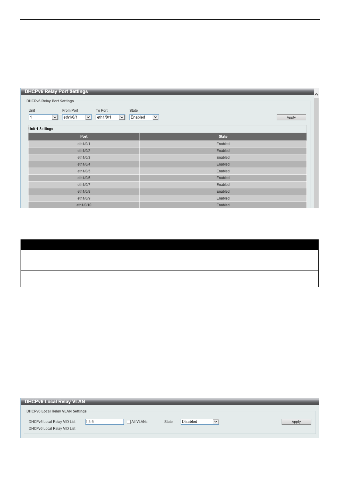
DGS-1520 Series Gigabit Ethernet Smart Managed Switch Web UI Reference Guide
84
DHCPv6 Relay Port Settings
This window is used to display and configure the DHCPv6 relay port settings.
To view the following window, click Management > DHCP > DHCPv6 Relay > DHCPv6 Relay Port Settings, as
shown below:
Figure 4-64 DHCPv6 Relay Port Settings Window
The fields that can be configured are described below:
Parameter Description
Unit
Select the Switch unit that will be used for this configuration here.
From Port - To Port
Select the range of ports that will be used for this configuration here.
State
Select to enable or disable the DHCPv6 relay port feature on the specified port(s)
here.
Click the Apply button to accept the changes made.
DHCPv6 Local Relay VLAN
This window is used to display and configure the DHCPv6 local relay VLAN settings. When DHCPv6 local relay is
enabled, it will add Option 37 and Option 18 to the request packets from the client. If the check state of Option 37 is
enabled, it will check the request packet from the client and drop the packet if it contains the Option 37 DHCPv6 relay
function. If disabled, the local relay function will always add Option 37 to request packets, whether the state of Option
37 is enabled or disabled. The DHCPv6 local relay function will directly forward the packet from the server to the
client.
To view the following window, click Management > DHCP > DHCPv6 Relay > DHCPv6 Local Relay VLAN, as
shown below:
Figure 4-65 DHCPv6 Local Relay VLAN Window
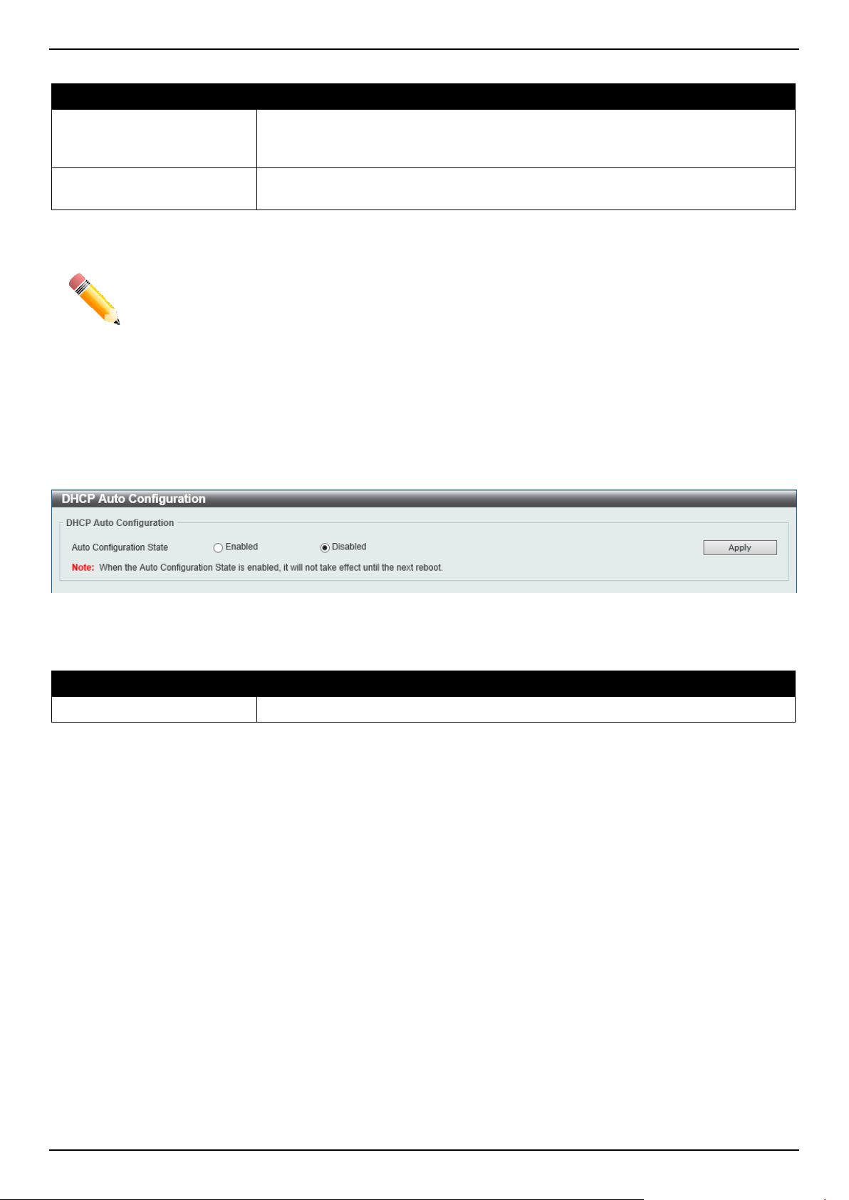
DGS-1520 Series Gigabit Ethernet Smart Managed Switch Web UI Reference Guide
85
The fields that can be configured are described below:
Parameter Description
DHCPv6 Local Relay VID
List
Enter the DHCPv6 local relay VLAN ID(s) here. More than one VLAN ID can be
entered here. Select the All VLANs option to apply this setting on all configured
VLANs on this Switch.
State
Select to enable or disable the DHCPv6 local relay feature on the specified
VLAN(s) here.
Click the Apply button to accept the changes made.
NOTE: When the state of the DHCPv6 relay port is disabled, the port will not relay or locally relay
received DHCPv6 packets.
DHCP Auto Configuration
This window is used to display and configure the DHCP auto-configuration function.
To view the following window, click Management > DHCP Auto Configuration, as shown below:
Figure 4-66 DHCP Auto Configuration Window
The fields that can be configured are described below:
Parameter Description
Auto Configuration State
Select this option to enable or disable the auto-configuration function.
Click the Apply button to accept the changes made.
DHCP Auto Image Settings
This window is used to display and configure the DHCP auto-image settings. During the start-up time of a Switch, this
function provides the capability of obtaining the image file form an external TFTP server whose IP address and file
name is carried in the DHCP OFFER message received from the DHCP server. The system then uses this image file
as the boot-up image. When the system boots up and the auto-image function is enabled, the Switch becomes a
DHCP client automatically.
The DHCP client will be activated to get the network settings from the DHCP server and the DHCP server includes the
TFTP server IP address and image filename with the message. The Switch then receives this information and triggers
the TFTP downloading function from the specified TFTP server. At this stage, the system will display the download
configuration parameters on the console. The layout is the same as using the download firmware command. After
the firmware download was completed, the Switch will then reboot immediately.
If both the auto-configuration and auto-image features are enabled at the same time, system will download the image
file first and then download the configuration. After this, the Switch will then save the configuration and reboot.
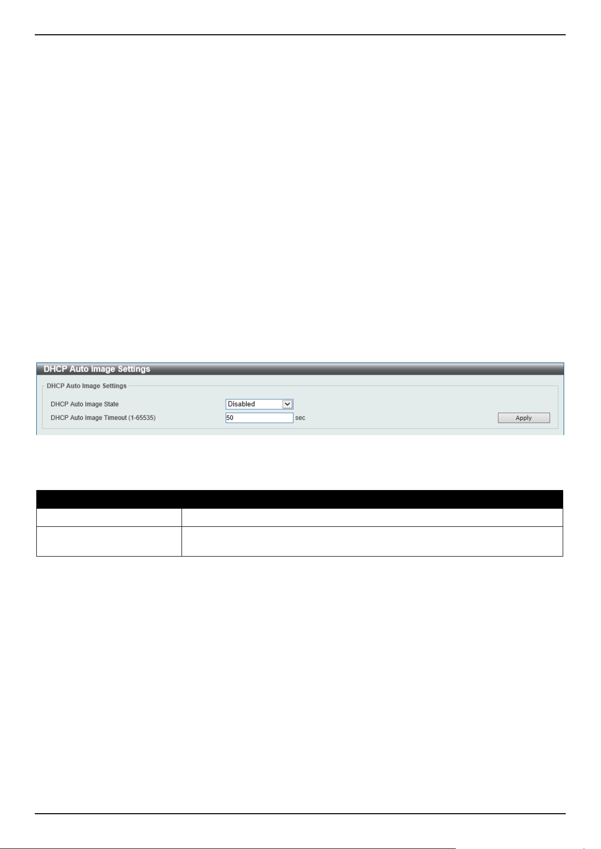
DGS-1520 Series Gigabit Ethernet Smart Managed Switch Web UI Reference Guide
86
The Switch will always check the downloaded firmware. If the version is the same as the current running firmware, the
Switch will terminate the auto-image process. The downloaded configuration, however, will still be executed if the
auto-configuration feature is also enabled.
This function is similar to the auto-configuration function. Both the image file and the configuration file must be placed
on the same TFTP server, as the DHCP option fields are not only used in the auto-image feature, but also in the auto-
configuration feature. The TFTP server IP address is still placed in the DHCP siaddr fields Option 66 or Option 150. If
Option 66, Option 150 and the siaddr fields exist in the DHCP response message at the same time, the Option 150
will be resolved first. If the system fails to connect to the TFTP server, then the system will resolve the Option 66, and
if the system still fails to connect the TFTP server, the siaddr field is the last choice.
When the Switch uses Option 66 to get the TFTP server name, it resolves Option 6 first to get the DNS server IP
address. If the Switch fails to connect to the DNS server or Option 6 does not exist in the response message, the
Switch will try to connect the DNS server already configured in the system manually.
Option 67 is used to identify the boot file when the 'file' field in the DHCP header has been used for DHCP options.
This can only be used in the DHCP auto-configuration mode and not the DHCP auto-image mode. For more
information, refer to RFC 2132. When specifying the image file name, the DHCP Option 125 (RFC 3925) must be
used. The Switch needs to check the enterprise-number1 field. If the value is not the D-Link vendor ID (171), the
Switch will stop the process. If the Option contains more than one field, only the first entry enterprise-number1 will be
used.
To view the following window, click Management > DHCP Auto Image Settings, as shown below:
Figure 4-67 DHCP Auto Image Settings Window
The fields that can be configured are described below:
Parameter Description
DHCP Auto Image State
Select to enable or disable the DHCP auto-image feature here.
DHCP Auto Image Timeout
Enter the timeout value of the DHCP auto-image feature here. The range is from 1
to 65535 seconds.
Click the Apply button to accept the changes made.
DNS
The Domain Name System (DNS) is used to map human-readable domain names to the IP addresses used by
computers to communicate. A DNS server performs name-to-address translation, and may need to contact several
name servers to translate a domain to an address. The address of the machine that supplies domain name service is
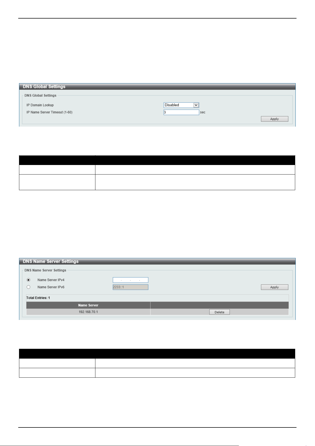
DGS-1520 Series Gigabit Ethernet Smart Managed Switch Web UI Reference Guide
87
often supplied by a DHCP or BOOTP server, or can be entered manually and configured into the operating system at
startup.
DNS Global Settings
This window is used to display and configure the global DNS settings.
To view the following window, click Management > DNS > DNS Global Settings, as shown below:
Figure 4-68 DNS Global Settings Window
The fields that can be configured in DNS Global Settings are described below:
Parameter Description
IP Domain Lookup
Select to enable or disable the IP domain lookup state here.
IP Name Server Timeout
Enter the maximum time to wait for a response from a specified name server. This
value is between 1 and 60 seconds.
Click the Apply button to accept the changes made.
DNS Name Server Settings
This window is used to display and configure the IP address of a domain name server.
To view the following window, click Management > DNS > DNS Name Server Settings, as shown below:
Figure 4-69 DNS Name Server Settings Window
The fields that can be configured are described below:
Parameter Description
Name Server IPv4
Select and enter the IPv4 address of the DNS server.
Name Server IPv6
Select and enter the IPv6 address of the DNS server.
Click the Apply button to accept the changes made.
Click the Delete button to remove the specified entry.
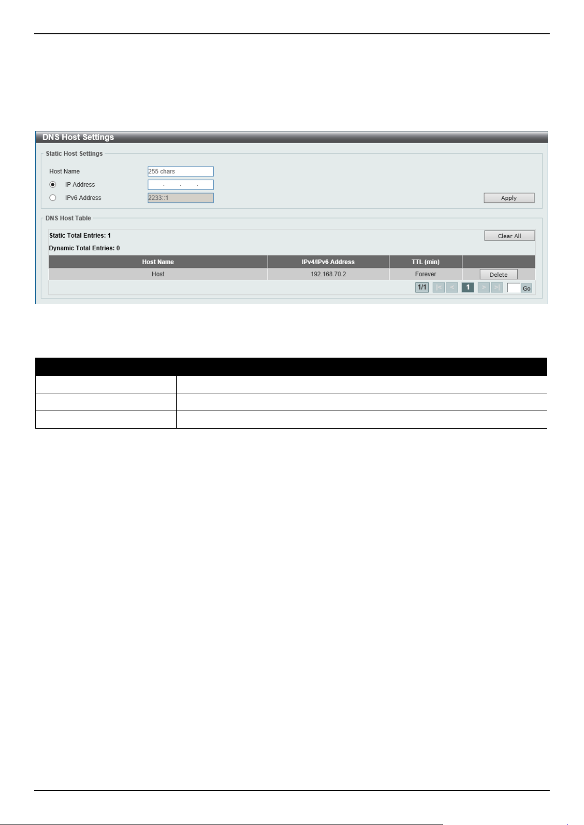
DGS-1520 Series Gigabit Ethernet Smart Managed Switch Web UI Reference Guide
88
DNS Host Settings
This window is used to display and configure the static mapping entry for the host name and the IP address in the host
table.
To view the following window, click Management > DNS > DNS Host Settings, as shown below:
Figure 4-70 DNS Host Settings Window
The fields that can be configured are described below:
Parameter Description
Host Name
Enter the host name of the equipment.
IP Address
Select and enter the IPv4 address of the equipment.
IPv6 Address
Select and enter the IPv6 address of the equipment.
Click the Apply button to accept the changes made.
Click the Clear All button to clear the information entered in all the fields on this page.
Click the Delete button to remove the specified entry.
Enter a page number and click the Go button to navigate to a specific page when multiple pages exist.
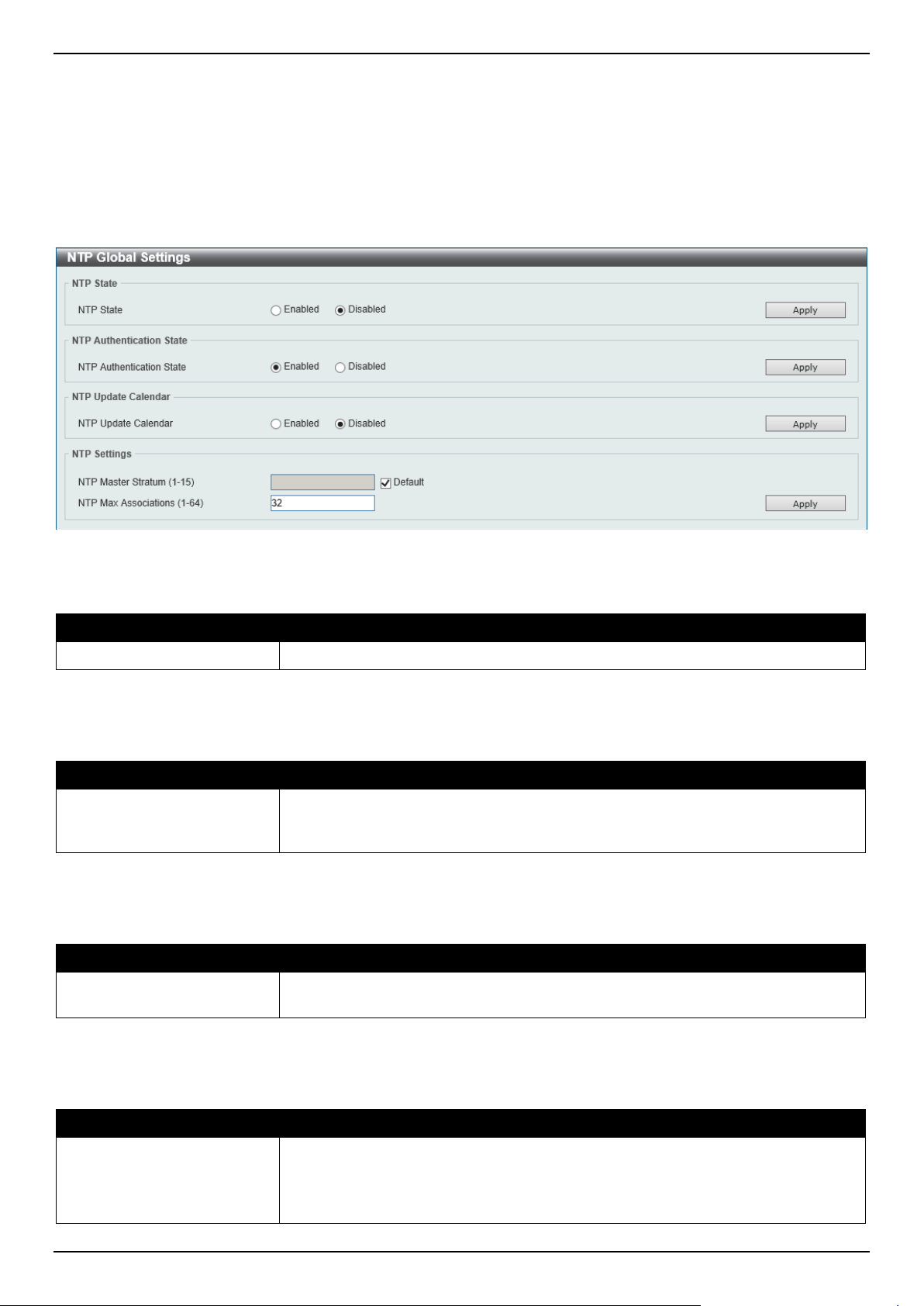
DGS-1520 Series Gigabit Ethernet Smart Managed Switch Web UI Reference Guide
89
NTP
NTP Global Settings
This window is used to display and configure the global Network Time Protocol (NTP) settings.
To view the following window, click Management > NTP > NTP Global Settings, as shown below:
Figure 4-71 NTP Global Settings Window
The fields that can be configured in NTP State are described below:
Parameter Description
NTP State
Select to globally enable or disable the NTP feature here.
Click the Apply button to accept the changes made.
The fields that can be configured in NTP Authentication State are described below:
Parameter Description
NTP Authentication State
Select to enable or disable the NTP authentication state here. When this feature is
enabled, networking nodes will not synchronize with the Switch unless it carries
one of the authentication keys.
Click the Apply button to accept the changes made.
The fields that can be configured in NTP Update Calendar are described below:
Parameter Description
NTP Update Calendar
Select to enable or disable the NTP update calendar feature here. This is used to
periodically update the hardware clock from an NTP source.
Click the Apply button to accept the changes made.
The fields that can be configured in NTP Settings are described below:
Parameter Description
NTP Master Stratum
Enter the NTP master stratum value here. This is used to configure the Real-Time
Clock (RTC) as an NTP master clock when an external NTP is not available. The
range is from 1 to 15.
Select the Default option to use the default value.
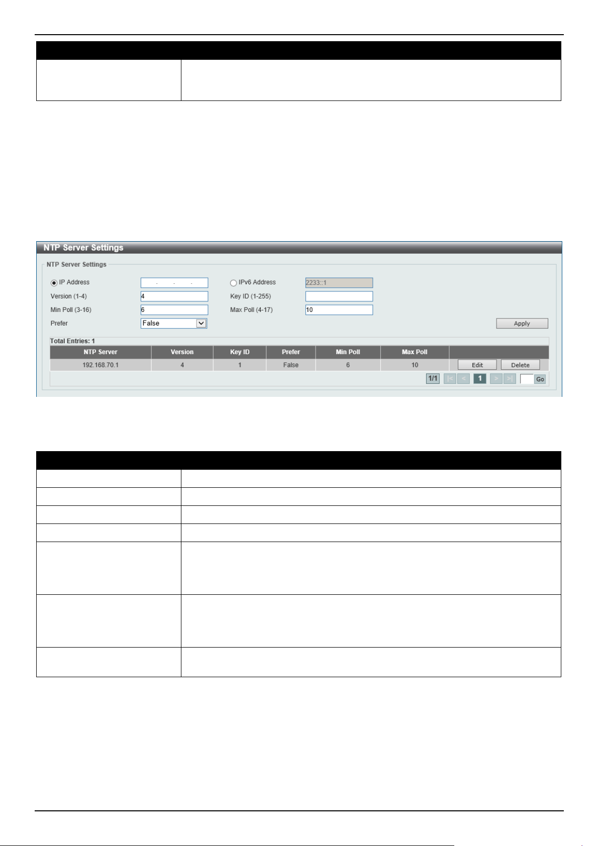
DGS-1520 Series Gigabit Ethernet Smart Managed Switch Web UI Reference Guide
90
Parameter Description
NTP Max Associations
Enter the NTP maximum association value here. This is used to configure the
maximum number of NTP peers and clients on the Switch. The range is from 1 to
64.
Click the Apply button to accept the changes made.
NTP Server Settings
This window is used to display and configure the NTP server settings. This is used to enable the Switch to
synchronize time with an NTP server.
To view the following window, click Management > NTP > NTP Server Settings, as shown below:
Figure 4-72 NTP Server Settings Window
The fields that can be configured are described below:
Parameter Description
IP Address
Select and enter the IPv4 address of the NTP server here.
IPv6 Address
Select and enter the IPv6 address of the NTP server here.
Version
Enter the NTP version number here. The range is from 1 to 4.
Key ID
Enter the authentication key ID here. The range is from 1 to 255.
Min Poll
Enter the minimum poll value here. This specifies the minimum poll interval for
NTP messages. This value is calculated as 2 to the power of the minimum poll
interval value specified. For example, if the value specified here is 6, the minimum
poll interval that will be used is 64 seconds (2
6
=64). The range is from 3 to 16.
Max Poll
Enter the maximum poll value here. This specifies the maximum poll interval for
NTP messages. This value is calculated as 2 to the power of the maximum poll
interval value specified. For example, if the value specified here is 6, the maximum
poll interval that will be used is 64 seconds (2
6
=64). The range is from 4 to 17.
Prefer
Select whether or not this entry will be the preferred server for synchronization.
Options to choose from are True and False.
Click the Apply button to accept the changes made.
Click the Edit button to re-configure the specific entry.
Click the Delete button to delete the specified entry.
Enter a page number and click the Go button to navigate to a specific page when multiple pages exist.
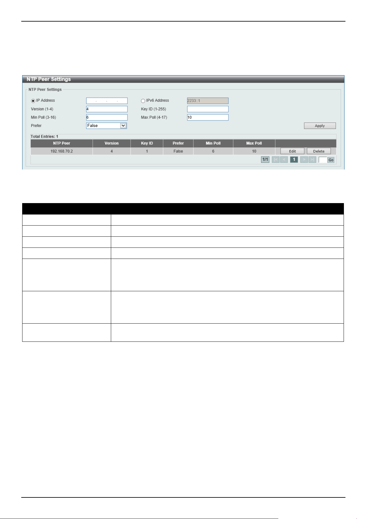
DGS-1520 Series Gigabit Ethernet Smart Managed Switch Web UI Reference Guide
91
NTP Peer Settings
This window is used to display and configure the NTP peer settings.
To view the following window, click Management > NTP > NTP Peer Settings, as shown below:
Figure 4-73 NTP Peer Settings Window
The fields that can be configured are described below:
Parameter Description
IP Address
Select and enter the IPv4 address of the NTP peer here.
IPv6 Address
Select and enter the IPv6 address of the NTP peer here.
Version
Enter the NTP version number here. The range is from 1 to 4.
Key ID
Enter the authentication key ID here. The range is from 1 to 255.
Min Poll
Enter the minimum poll value here. This specifies the minimum poll interval for
NTP messages. This value is calculated as 2 to the power of the minimum poll
interval value specified. For example, if the value specified here is 6, the minimum
poll interval that will be used is 64 seconds (2
6
=64). The range is from 3 to 16.
Max Poll
Enter the maximum poll value here. This specifies the maximum poll interval for
NTP messages. This value is calculated as 2 to the power of the maximum poll
interval value specified. For example, if the value specified here is 6, the maximum
poll interval that will be used is 64 seconds (2
6
=64). The range is from 4 to 17.
Prefer
Select whether or not this entry will be the preferred peer for synchronization.
Options to choose from are True and False.
Click the Apply button to accept the changes made.
Click the Edit button to re-configure the specific entry.
Click the Delete button to delete the specified entry.
Enter a page number and click the Go button to navigate to a specific page when multiple pages exist.
NTP Access Group Settings
This window is used to display and configure the NTP access group settings. The NTP implements a general purpose
Access Control List (ACL) containing address/match entries sorted first by increasing address values and then by
increasing mask values. A match occurs when the bitwise AND of the mask and the packet source address is equal to
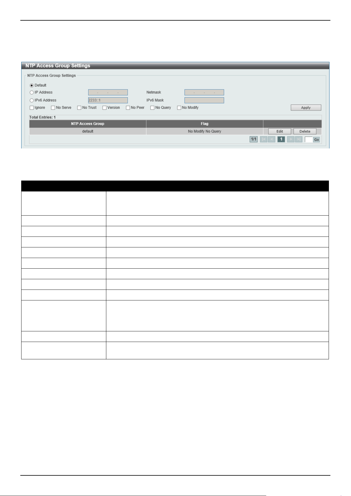
DGS-1520 Series Gigabit Ethernet Smart Managed Switch Web UI Reference Guide
92
the bitwise AND of the mask and address in the list. The list is searched in order with the last match found defining the
restriction flags associated with the entry.
To view the following window, click Management > NTP > NTP Access Group Settings, as shown below:
Figure 4-74 NTP Access Group Settings Window
The fields that can be configured are described below:
Parameter Description
Default
Select this option to specify to use the default IPv4 (0.0.0.0/0.0.0.0) or IPv6 (::/::)
address. The default IP address is always included with the lowest priority in the
list.
IP Address
Select and enter the host IPv4 address here.
Netmask
Enter the IPv4 netmask of the host network here.
IPv6 Address
Select and enter the host IPv6 address here.
IPv6 Mask
Enter the IPv6 prefix length of the host network here.
Ignore
Select this option to deny all packets, including NTP control queries.
No Serve
Select this option to deny all packets except NTP control queries.
No Trust
Select this option to deny packets that are not cryptographically authenticated.
Version
Select this option to deny packets that mismatch the current NTP version.
No Peer
Select this option to deny packets that might mobilize an association unless
authenticated. The packets include broadcast, symmetric-active and many cast
server packets when a configured association does not exist. Note that this flag
does not apply to packets that do not attempt to mobilize an association.
No Query
Select this option to deny all NTP control queries.
No Modify
Select this option to deny the NTP control queries that attempt to modify the state
of the server.
Click the Apply button to accept the changes made.
Click the Edit button to modify the specified entry.
Click the Delete button to delete the specified entry.
Enter a page number and click the Go button to navigate to a specific page when multiple pages exist.
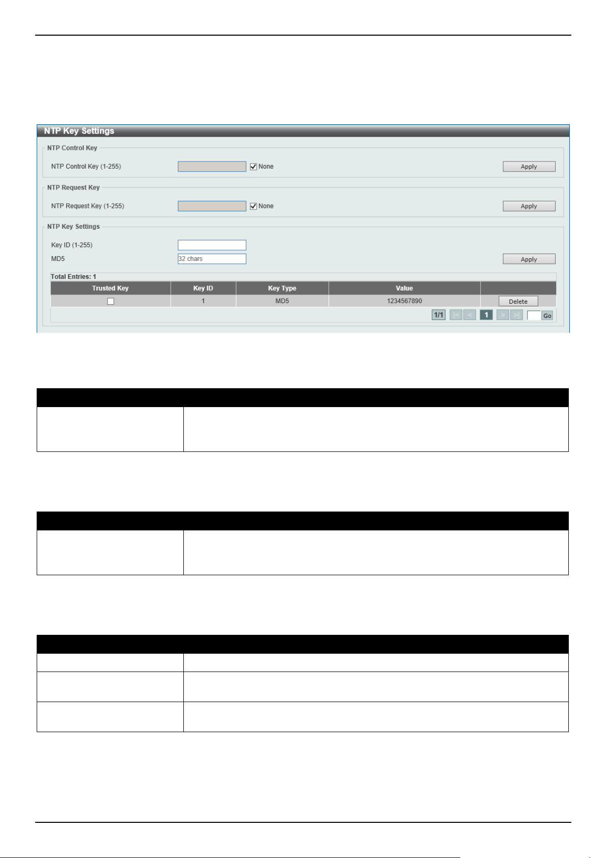
DGS-1520 Series Gigabit Ethernet Smart Managed Switch Web UI Reference Guide
93
NTP Key Settings
This window is used to display and configure the NTP key settings.
To view the following window, click Management > NTP > NTP Key Settings, as shown below:
Figure 4-75 NTP Key Settings Window
The fields that can be configured in NTP Control Key are described below:
Parameter Description
NTP Control Key
Enter the NTP control key here. This is used to define the key ID for the NTP
control messages. The range is from 1 to 255.
Select the None option to disable this feature.
Click the Apply button to accept the changes made.
The fields that can be configured in NTP Request Key are described below:
Parameter Description
NTP Request Key
Enter the NTP request key here. This is used to define the key ID for NTP mode 7
packets, used by the ntpdc utility program. The range is from 1 to 255.
Select the None option to disable this feature.
Click the Apply button to accept the changes made.
The fields that can be configured in NTP Key Settings are described below:
Parameter Description
Key ID
Enter the NTP key ID here. The range is from 1 to 255.
MD5
Enter the MD5 authentication key string here. This string can be up to 32
characters long.
Trusted Key
Select this option to specify that the key for a peer NTP system is trusted for
authentication.
Click the Apply button to accept the changes made.
Click the Delete button to delete the specified entry.
Enter a page number and click the Go button to navigate to a specific page when multiple pages exist.
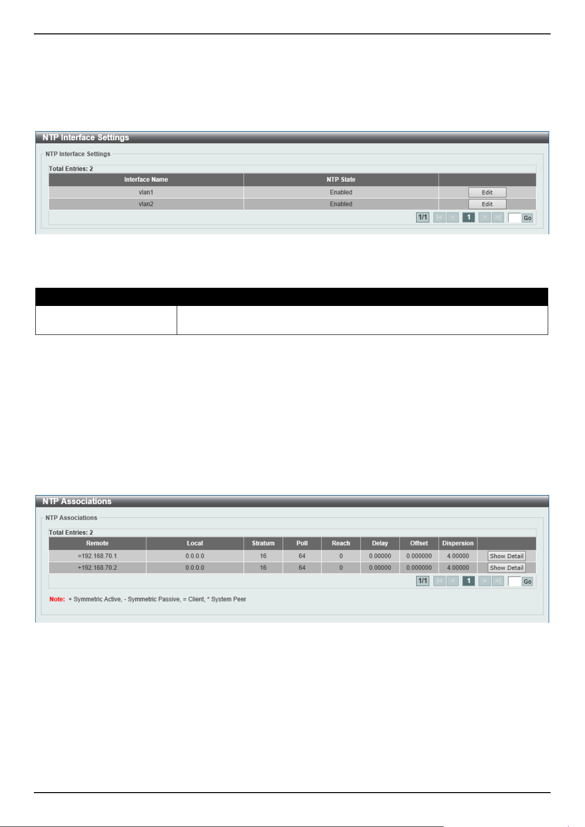
DGS-1520 Series Gigabit Ethernet Smart Managed Switch Web UI Reference Guide
94
NTP Interface Settings
This window is used to display and configure the NTP interface settings. This is used to either prevent or allow an
interface from receiving NTP packets.
To view the following window, click Management > NTP > NTP Interface Settings, as shown below:
Figure 4-76 NTP Interface Settings Window
The fields that can be configured are described below:
Parameter Description
NTP State After click the Edit button, select to enable or disable the NTP state for the
specified VLAN interface here.
Click the Edit button to re-configure the specific entry.
Click the Apply button to accept the changes made.
Enter a page number and click the Go button to navigate to a specific page when multiple pages exist.
NTP Associations
This window is used to view NTP association information.
To view the following window, click Management > NTP > NTP Associations, as shown below:
Figure 4-77 NTP Associations Window
Click the Show Detail button to view detailed information about the entry.
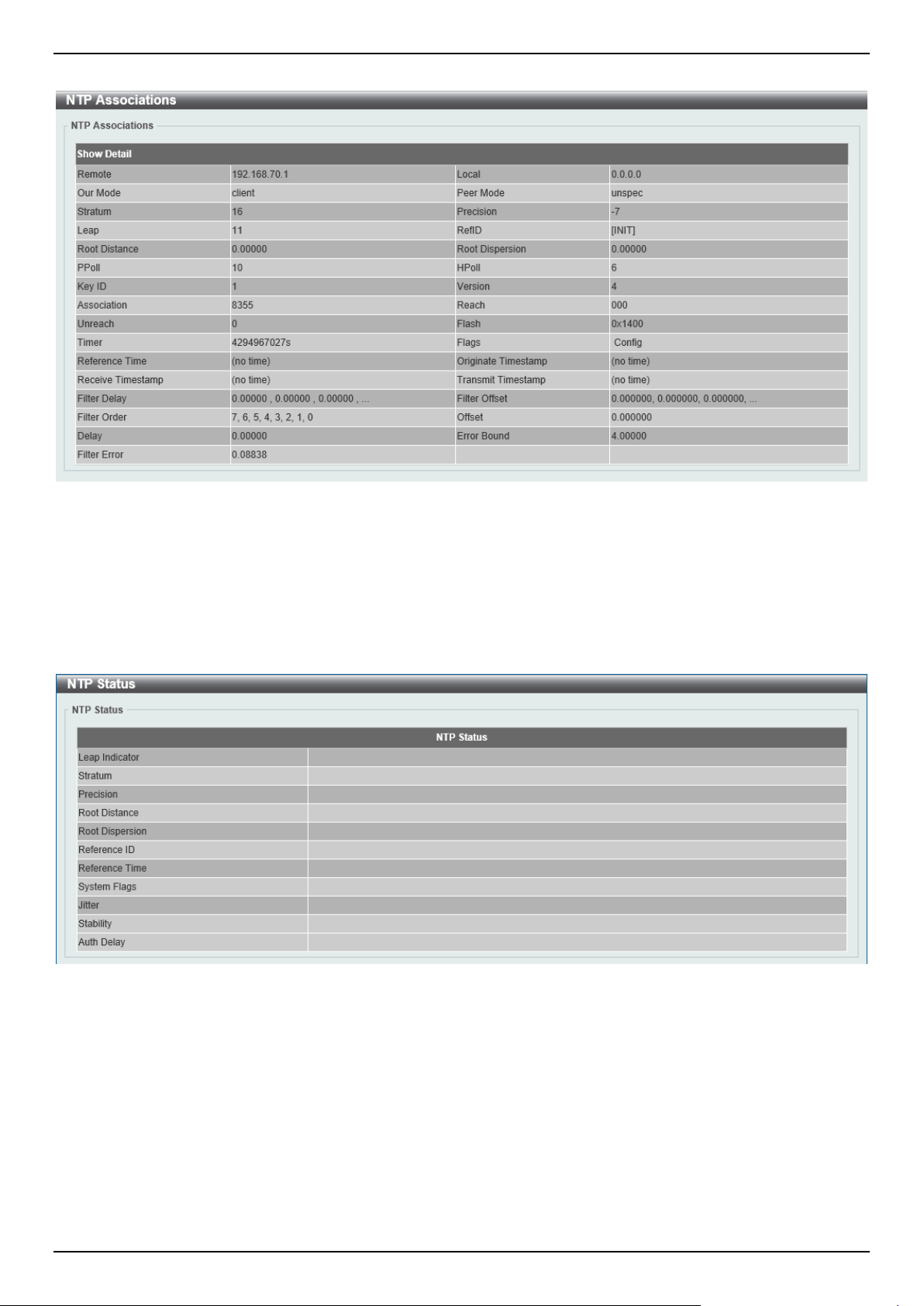
DGS-1520 Series Gigabit Ethernet Smart Managed Switch Web UI Reference Guide
95
After clicking the Show Detail button, the following window will appear:
Figure 4-78 NTP Associations (Show Detail) Window
NTP Status
This window is used to view NTP status information.
To view the following window, click Management > NTP > NTP Status, as shown below:
Figure 4-79 NTP Status Window
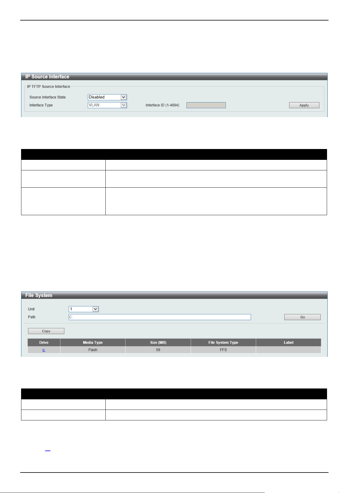
DGS-1520 Series Gigabit Ethernet Smart Managed Switch Web UI Reference Guide
96
IP Source Interface
This window is used to display and configure the IP source interface settings.
To view the following window, click Management > IP Source Interface, as shown below:
Figure 4-80 IP Source Interface Window
The fields that can be configured in IP TFTP Source Interface are described below:
Parameter Description
Source Interface State
Select to enable or disable the IP TFTP source interface state here.
Interface Type After enabling the Source Interface State option, select the interface type here.
Options to choose from are Loopback, Mgmt, and VLAN.
Interface ID
Enter the interface ID here. For loopback interfaces, this value is from 1 to 8.
For the management interface (Mgmt), this value can only be 0.
For VLAN interfaces, this value is from 1 to 4094.
Click the Apply button to accept the changes made.
File System
This window is used to view, manage, and configure the Switch file system.
To view the following window, click Management > File System, as shown below:
Figure 4-81 File System Window
The fields that can be configured are described below:
Parameter Description
Unit
Select the Switch unit that will be used for this configuration here.
Path
Enter the path string.
Click the Go button to navigate to the path entered.
Click the Copy button to copy a specific file to the Switch.
Click the c: hyperlink to navigate the C: drive
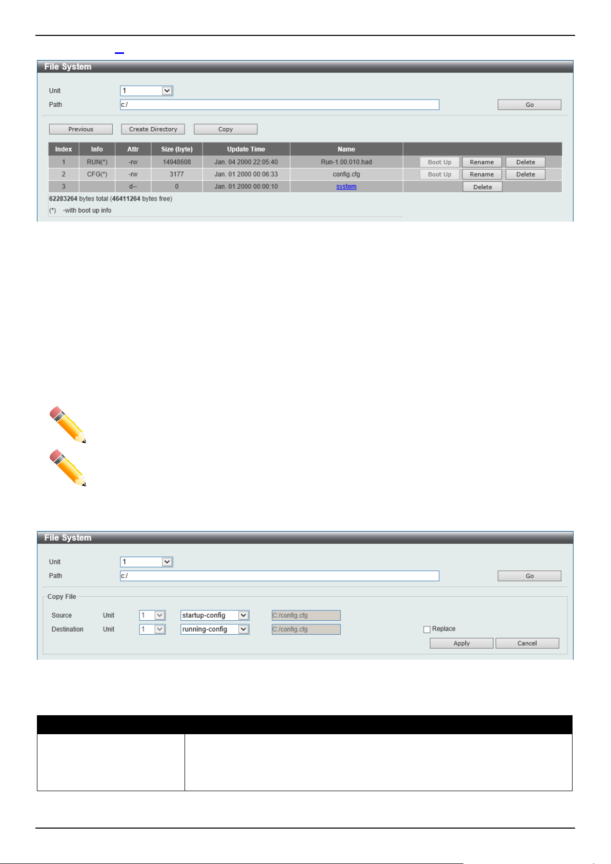
DGS-1520 Series Gigabit Ethernet Smart Managed Switch Web UI Reference Guide
97
After clicking the c: hyperlink, the following window will appear:
Figure 4-82 File System (Drive) Window
Click the Go button to navigate to the path entered.
Click the Previous button to return to the previous window.
Click the Create Directory to create a new directory within the file system of the Switch.
Click the Copy button to copy a specific file to the Switch.
Click the Boot Up button to set a specific runtime image as the boot up image.
Click the Rename button to rename a specific file name.
Click the Delete button to remove a specific file from the file system.
NOTE: If the boot configuration file is damaged, the Switch will automatically revert back to the
default configuration.
NOTE: If the boot image file is damaged, the Switch will automatically use the backup image file in
the next boot up.
Click the Copy button to see the following window.
Figure 4-83 File System (Copy) Window
The fields that can be configured in Copy File are described below:
Parameter Description
Source Select the source Switch Unit ID and type of source file that will be copied here.
Options to choose from are startup-config and Source File.
Only after selecting the Source File option can the source file path and filename
be entered in the space provided.

DGS-1520 Series Gigabit Ethernet Smart Managed Switch Web UI Reference Guide
98
Parameter Description
Destination Select the destination Switch Unit ID and type of destination file that will be copied
here. Options to choose from are startup-config, running-config, and
Destination File.
Only after selecting the Destination File option can the destination file path and
filename be entered in the space provided. Tick the Replace check box to replace
the current running configuration with the indicated configuration file.
Click the Apply button to initiate the copy.
Click the Cancel button the discard the process.
Stacking
Switches in this series support stacking up to 8 switches together while being managed through one console
connection on the master switch, or by an IP address through the MGMT port if the master is a DGS-1520-28/52, or
by multiple IP addresses through any of the RJ45/SFP+ ports using Telnet, the Web UI, and SNMP. This cost-
effective switch provides an affordable solution for administrators to upgrade their networks using the stacking ports to
scale and stack the Switches. This increases overall reliability, serviceability, and availability.
• Duplex Chain - This topology stacks switches together in a chain-link format. Using this method, data transfer
is only possible in one direction. If there is a break in the chain, data transfer will be affected.
• Duplex Ring - This topology stacks switches in a ring or circle format where data can be transferred in two
directions. It is very resilient due to the fact that, if there is a break in the ring, data can still be transferred
through the stacking cables between switches in the stack using the alternate path.
Switches in the series can be physically stacked with optical fiber cables, standard Ethernet cables, or Direct Attached
Cables (DACs) with SFP+ connectors. Only the last 4 ports on the Switch can be used for physical stacking. Physical
stacking needs to be enabled and can be configured to support a 2-port or 4-port stacking configuration.
When the 2-port 10GBASE-T stacking configuration is used, a full-duplex speed of up to 40Gbps is used between
two switches.
• The DGS-1520-28 uses ports 25 (SIO1) and 26 (SIO2) for 2-port stacking.
• The DGS-1520-28MP uses ports 25 (SIO1) and 26 (SIO2) for 2-port stacking.
• The DGS-1520-52 uses ports 49 (SIO1) and 50 (SIO2) for 2-port stacking.
• The DGS-1520-52MP uses use physical ports 49 (SIO1) and 50 (SIO2) for 2-port stacking.
When the 2-port SFP+ stacking configuration is used, a full-duplex speed of up to 40Gbps is used between two
switches.
• The DGS-1520-28 uses ports 27 (SIO1) and 28 (SIO2) for 2-port stacking.
• The DGS-1520-28MP uses ports 27 (SIO1) and 28 (SIO2) for 2-port stacking.
• The DGS-1520-52 uses ports 51 (SIO1) and 52 (SIO2) for 2-port stacking.
• The DGS-1520-52MP uses ports 51 (SIO1) and 52 (SIO2) for 2-port stacking.
When the 4-port stacking configuration is used, a full-duplex speed of up to 80Gbps is used between two switches
using four physical ports aggregated into two virtual stacking ports.
• The DGS-1520-28 uses ports 25 (SIO1), 26 (SIO2), 27 (SIO1), and 28 (SIO2) for 4-port stacking.
• The DGS-1520-28MP uses ports 25 (SIO1), 26 (SIO2), 27 (SIO1), and 28 (SIO2) for 4-port stacking.
• The DGS-1520-52 uses ports 49 (SIO1), 50 (SIO2), 51 (SIO1), and 52 (SIO2) for 4-port stacking.
• The DGS-1520-52MP uses ports 49 (SIO1), 50 (SIO2), 51 (SIO1), and 52 (SIO2) for 4-port stacking.
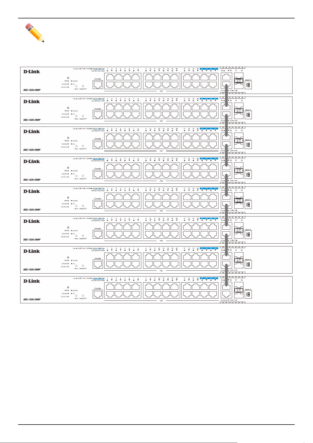
DGS-1520 Series Gigabit Ethernet Smart Managed Switch Web UI Reference Guide
99
NOTE: When stacking is enabled, 2 or 4 of the last 4 ports are dedicated stacking ports and cannot
be used for any other purpose. These ports are only able to perform stacking when stacking
is enabled.
In the following diagram, switches are stacked in the Duplex Chain topology using the two 10GBASE-T ports.
Figure 4-84 Duplex Chain Stacking Topology
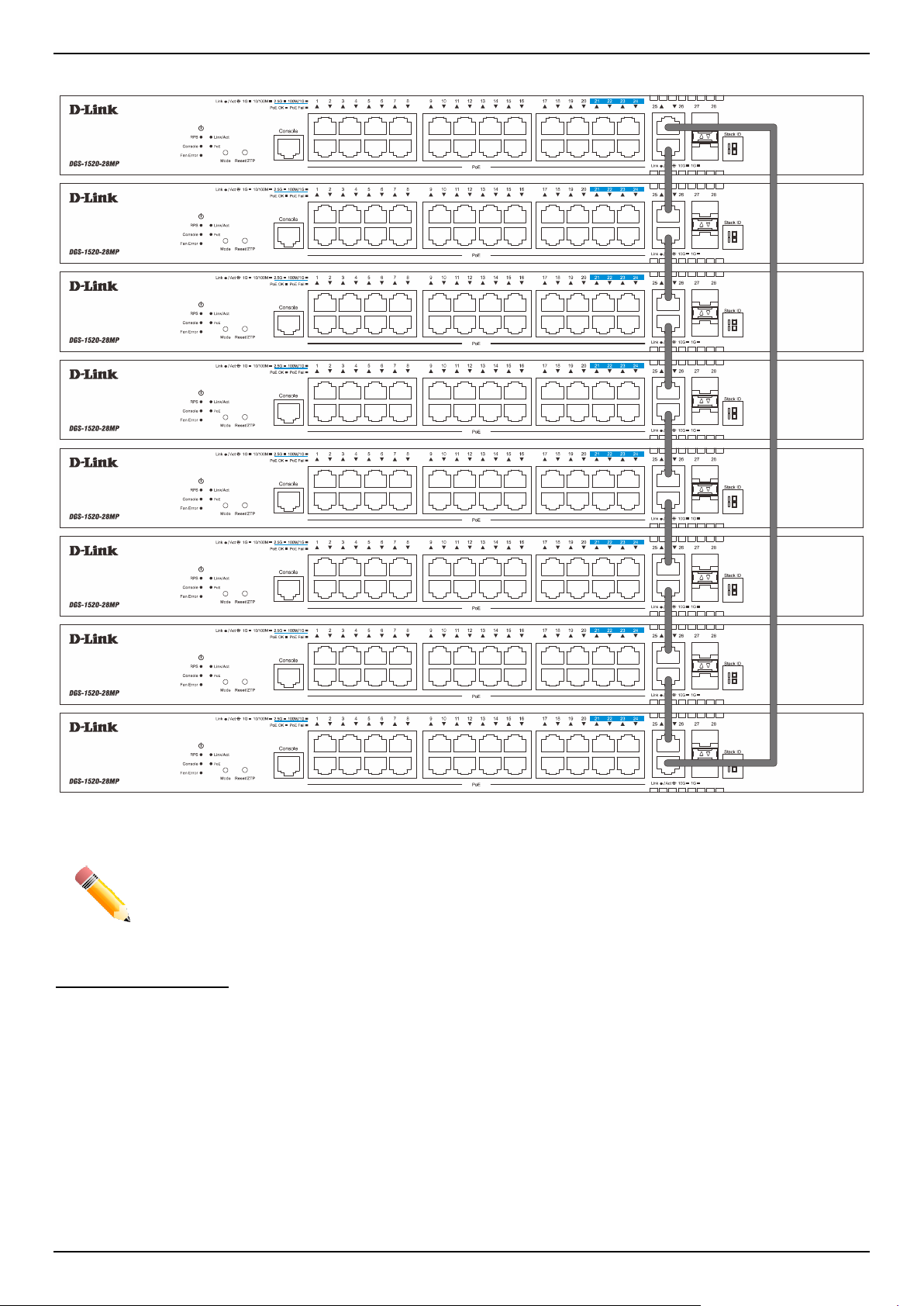
DGS-1520 Series Gigabit Ethernet Smart Managed Switch Web UI Reference Guide
100
In the following diagram, switches are stacked in the Duplex Ring topology using the two 10GBASE-T ports.
Figure 4-85 Duplex Ring Stacking Topology
NOTE: Stacking Input/Output logical port 1 (SIO1) and SIO2 are logical stacking port pairs. A logical
stacking port pair must always be connected to the same Switch in the stack. Splitting logical
stacking port pairs between different Switches in the stack might not guarantee a stable
stacking connection. See Stacking Bandwidth on page 103 for more information.
Switch Roles in a Stack
Within each of these topologies, each Switch plays a role in the Switch stack. These roles can be set by the user per
individual Switch, or if desired, can be automatically determined by the Switch stack.
Three possible roles exist when stacking with the Switch.
• Primary Master - The Primary Master is the leader of the stack. It will maintain normal operations, monitor
operations and the running topology of the Stack. This Switch will also assign Stack Unit IDs, synchronize
configurations, and transmit commands to remaining Switches in the Switch stack. The Primary Master can be
manually set by assigning this Switch the highest priority (a lower number denotes a higher priority) before
physically assembling the stack, or it can be determined automatically by the stack through an election process.
This determines the lowest MAC address and then will assign that Switch as the Primary Master if all priorities
are the same. The Primary master is physically displayed by the seven segment LED to the far right on the front
panel of the Switch where the LED will flash between its given Box ID and 'H'.

DGS-1520 Series Gigabit Ethernet Smart Managed Switch Web UI Reference Guide
101
• Backup Master - The Backup Master is the backup to the Primary Master, and will take over the functions of
the Primary Master if the Primary Master fails or is removed from the Stack. It also monitors the status of
neighboring Switches in the stack, will perform commands assigned to it by the Primary Master and will monitor
the running status of the Primary Master. The Backup Master can be set by the user by assigning this Switch
the second highest priority (a lower number denotes a higher priority) before physically assembling the stack, or
it can be determined automatically by the stack through an election process. This determines the second lowest
MAC address and then will assign that Switch as the Backup Master if all priorities are the same. The Backup
master is physically displayed by the seven segment LED to the far right on the front panel of the Switch where
the LED will flash between its given Box ID and 'h'.
• Slave - Slave Switches constitute the rest of the Switch stack and although not Primary or Backup Masters,
they can be placed into these roles when these other two roles fail or are removed from the stack. Slave
Switches perform operations requested by the master, monitor the status of the stack topology, and adhere to
the Backup Master's commands once it becomes Primary Master. Slave Switches will do a self-check to
determine if they are to become the Backup Master if the Backup Master is promoted to the Primary Master, or
if the Backup Master fails or is removed from the Switch stack. If both Primary and Backup masters fail, or are
removed from the Switch stack, the Switch will determine if it is to become the Primary Master. These roles will
be determined by priority and if this is the same, by the lowest MAC address.
Once Switches have been assembled in the topology desired by the user and powered on, the stack will undergo
three processes until it reaches a functioning state.
• Initialization State - This is the first state of the stack, where the runtime codes are set and initialized and the
system conducts a peripheral diagnosis to determine each individual Switch is functioning properly.
• Master Election State - Once the runtime codes are loaded and initialized, the stack will undergo the Master
Election State where it will discover the type of topology used, elect a Primary Master and then a Backup
Master.
• Synchronization State - Once the Primary Master and the Backup Master have been established, the Primary
Master will assign Stacking Unit IDs to Switches in the stack, synchronize configurations for all Switches and
then transmit commands to the rest of the Switches based on the configuration of the Primary Master.
Once these steps have been completed, the Switch stack will enter a normal operating mode.
Stack Switch Swapping
The stacking feature of the Switch supports hot swapping of Switches in and out of the running stack. Users may
remove or add Switches to the stack without powering down or largely affecting the transfer of data between Switches
in the stack, as long as some basic rules are adhered to.
When Switches are 'hot inserted' into the running stack, the new Switch may take on the Primary Master, Backup
Master or Slave role, depending on configuration set on the newly added Switch, such as priority or MAC address.
Yet, if adding two stacks together that have both previously undergone the election process, and therefore both have
a Primary Master and a Backup master, a new Primary Master will be elected from one of the already existing Primary
Masters, based on priority or MAC address. This Primary Master will take over all of the Primary Master's roles for all
new Switches that were hot inserted. This process is done using discovery packets that circulate through the Switch
stack every 1.5 seconds until the discovery process has been completed.
The 'hot remove' action means removing a device from the stack while the stack is still running. The hot removal is
detected by the stack when it fails to receive heartbeat packets during its specified interval from a device, or when one
of the stacking ports links is down. Once the device has been removed, the remaining Switches will update their
stacking topology database to reflect the change. Any one of the three roles, Primary Master, Backup Master, or
Slave, may be removed from the stack, yet a different process occurs for each specific device removal.
If a Slave device has been removed, the Primary Master will inform other Switches of the hot remove of this device
through the use of unit leave messages. Switches in the stack will clear the configuration of the unit removed, and
dynamically learned databases, such as ARP, will also be cleared.
If the Backup Master has been hot removed, a new Backup Master will be chosen through the election process
previously described. Switches in the stack will clear the configuration of the unit removed, and dynamically learned
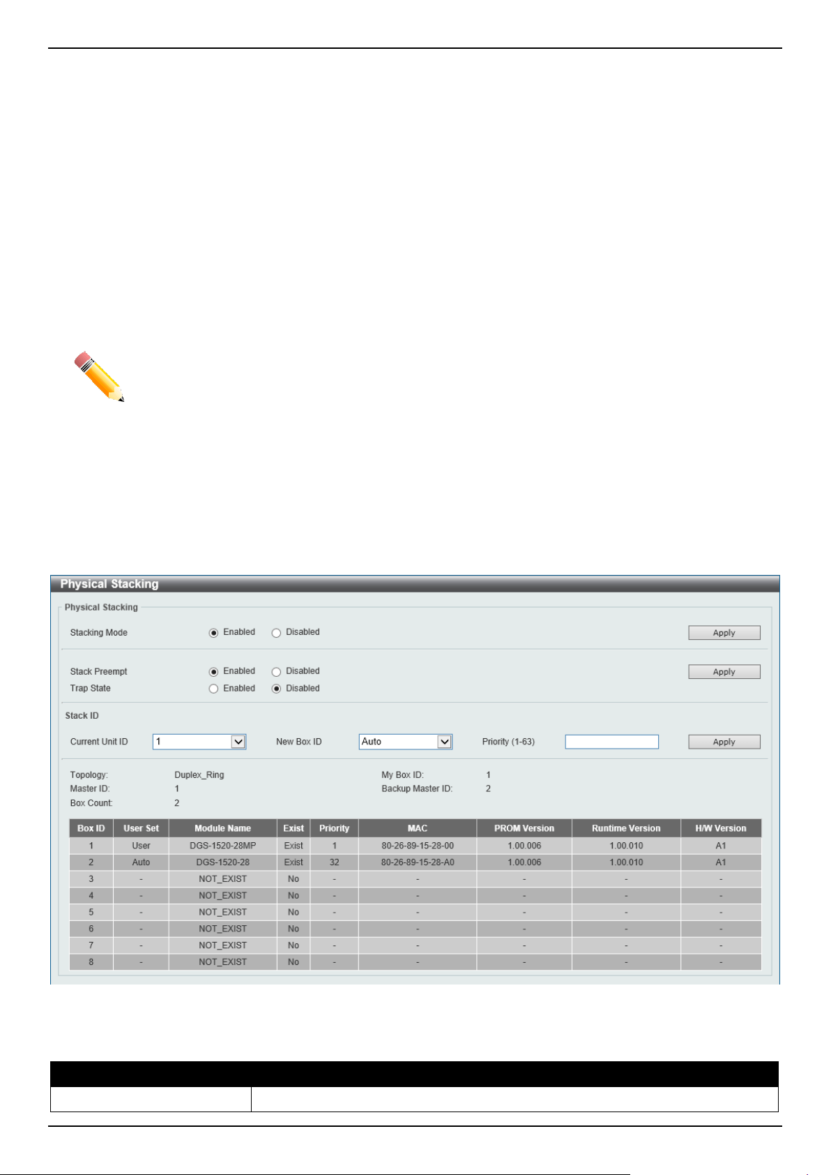
DGS-1520 Series Gigabit Ethernet Smart Managed Switch Web UI Reference Guide
102
databases, such as ARP, will also be cleared. Then the Backup Master will begin backing up the Primary Master when
the database synchronization has been completed by the stack.
If the Primary Master is removed, the Backup Master will assume the Primary Master's role and a new Backup Master
will be chosen using the election process. Switches in the stack will clear the configuration of the unit removed, and
dynamically learned databases, such as ARP, will also be cleared. The new Primary Master will inherit the MAC and
IP address of the previous Primary Master to avoid conflict within the stack and the network itself.
If both the Primary Master and the Backup Master are removed, the election process is immediately initiated, and a
new Primary Master and Backup Master are elected. Switches in the stack will clear the configuration of the units that
have been removed, and dynamically learned databases, such as ARP, will also be cleared. Static Switch
configuration still remains in the database of the remaining Switches in the stack and those functions will not be
affected.
NOTE: If there is a Box ID conflict when the stack is in the discovery phase, the device will enter a
special standalone topology mode. Users can only get device information, configure Box
IDs, save and reboot. All stacking ports will be disabled and an error message will be
produced on the local console port of each device in the stack. Users must reconfigure Box
IDs and reboot the stack to rectify the problem.
Physical Stacking
This window is used to display and configure the physical stacking settings.
To view the following window, click Management > Stacking > Physical Stacking, as shown below:
Figure 4-86 Physical Stacking Window
The fields that can be configured in Physical Stacking are described below:
Parameter Description
Stacking Mode
Select this option to enable or disable the stacking mode.
DGS-1520 Series Gigabit Ethernet Smart Managed Switch Web UI Reference Guide
103
Parameter Description
Stack Preempt
Select this option to enable or disable preemption of the master role when a unit
with a higher priority is added to the Switch.
Trap State
Select this option to enable or disable stacking related SNMP traps.
Click the Apply button to accept the changes made.
The fields that can be configured in Stack ID are described below:
Parameter Description
Current Unit ID
Select the unit ID of the Switch in the stack.
New Box ID Select the new box ID for the Switch that is selected in the Current Unit ID field.
The range is from 1 to 8. Auto will automatically assign a box number to the
Switch in the Switch stack.
Priority
Enter the priority of the Switch stacking unit. The range is from 1 to 63.
Click the Apply button to accept the changes made.
Stacking Bandwidth
This window is used to display and configure the stacking bandwidth settings. Physical stacking needs to be enabled
and can be configured to support either a 2-port or a 4-port stacking configuration.
• 2-Port-10G-Base-T/2-Port (SFP+) - A full-duplex speed of up to 40Gbps is used between two Switches.
• 4-port - A full-duplex speed of up to 80Gbps is used between two Switches using four physical ports
aggregated into two virtual stacking ports.
SIO1 is a logical stacking port pair and SIO2 is a logical stacking port pair. A logical stacking port pair must always be
connected to the same Switch in the stack. Splitting logical stacking port pairs between different Switches in the stack
might not guarantee a stable stacking connection.
The following table lists the logical stacking port pair for each stacking configuration:
Switch
2-Port 4-Port
SIO1 SIO2 SIO1 SIO2
DGS-1520-28
Port 25 or 27 Port 26 or 28 Ports 25 and 26 Ports 27 and 28
DGS-1520-28MP
Port 25 or 27 Port 26 or 28 Ports 25 and 26 Ports 27 and 28
DGS-1520-52
Port 49 or 51 Port 50 or 52 Ports 49 and 50 Ports 51 and 52
DGS-1520-52MP
Port 49 or 51 Port 50 or 52 Ports 49 and 50 Ports 51 and 52
NOTE: The stacking bandwidth must be configured before the Switch is stacked with other
Switches.
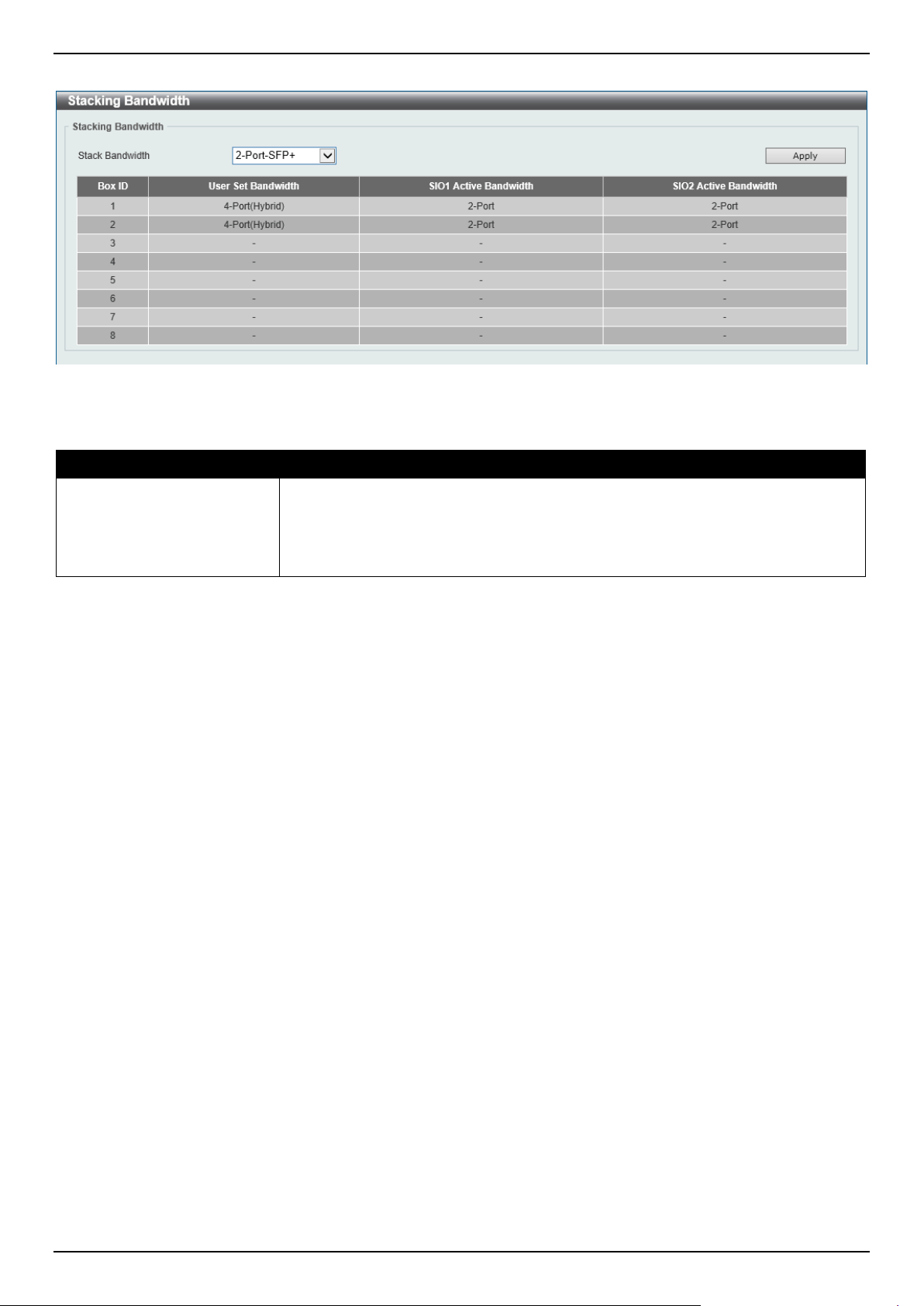
DGS-1520 Series Gigabit Ethernet Smart Managed Switch Web UI Reference Guide
104
To view the following window, click Management > Stacking > Stacking Bandwidth, as shown below:
Figure 4-87 Stacking Bandwidth Window
The fields that can be configured are described below:
Parameter Description
Stack Bandwidth
Select the stacking bandwidth here. Option to choose from are:
• 2-Port-SFP+ - Specifies to use the two SFP+ stacking ports.
• 2-Port-10G-Base-T - Specifies to use the two RJ45 stacking ports.
• 4-Port-Hybrid - Specifies to use all the stacking ports.
Click the Apply button to accept the changes made.
Virtual Stacking (SIM)
D-Link Single IP Management (SIM) is a concept that will stack Switches together over Ethernet instead of using
stacking ports or modules. There are some advantages in implementing the Single IP Management feature:
• SIM can simplify management of small workgroups or wiring closets while scaling the network to handle
increased bandwidth demand.
• SIM can reduce the number of IP address needed in your network.
• SIM can eliminate any specialized cables for stacking connectivity and remove the distance barriers that
typically limit your topology options when using other stacking technology.
Switches using D-Link Single IP Management (labeled here as SIM) must conform to the following rules:
• SIM is an optional feature on the Switch and can easily be enabled or disabled through the Command Line
Interface or Web Interface. SIM grouping has no effect on the normal operation of the Switch in the network.
• There are three classifications for Switches using SIM. The Commander Switch (CS), which is the master
Switch of the group, Member Switch (MS), which is a Switch that is recognized by the CS a member of a SIM
group, and a Candidate Switch (CaS), which is a Switch that has a physical link to the SIM group but has not
been recognized by the CS as a member of the SIM group.
• A SIM group can only have one Commander Switch (CS).
• A SIM group accepts up to 32 Switches (numbered 1-32), not including the Commander Switch (numbered 0).
• Members of a SIM group must be in the same Layer 2 network.
• There is no limit to the number of SIM groups in the same IP subnet (broadcast domain); however, a single
Switch can only belong to one group.
• If multiple VLANs are configured, the SIM group will only utilize the management VLAN on any Switch.
• SIM allows intermediate devices that do not support SIM. This enables the user to manage Switches that are
more than one hop away from the CS.

DGS-1520 Series Gigabit Ethernet Smart Managed Switch Web UI Reference Guide
105
The SIM group is a group of Switches that are managed as a single entity. The Switch may take on three different
roles:
• Commander Switch (CS) - This is a Switch that has been manually configured as the controlling device for a
group, and takes on the following characteristics:
o It has an IP Address.
o It is not a CS or member Switch of another SIM group.
o It is connected to the member Switches through its management VLAN.
• Member Switch (MS) - This is a Switch that has joined a SIM group and is accessible from the CS, and it takes
on the following characteristics:
o It is not a CS or MS of another SIM group.
o It is connected to the CS through the CS management VLAN.
• Candidate Switch (CaS) - This is a Switch that is ready to join a SIM group but is not yet a member of the SIM
group. The Candidate Switch may join the SIM group of the Switch by manually configuring it to be a MS of a
SIM group. A Switch configured as a CaS is not a member of a SIM group and will take on the following
characteristics:
o It is not a CS or MS of another Single IP group.
o It is connected to the CS through the CS management VLAN
The following rules also apply to the above roles:
• Each device begins in a CaS state.
• A CS must change its role to CaS and then to MS, to become a MS of a SIM group. Thus, the CS cannot
directly be converted to a MS.
• The user can manually configure a CS to become a CaS.
• A MS can become a CaS by:
o Being configured as a CaS through the CS.
o If report packets from the CS to the MS time out.
• The user can manually configure a CaS to become a CS
• The CaS can be configured through the CS to become a MS.
After configuring one Switch to operate as the CS of a SIM group, additional Switches may join the group by manually
configuring the Switch to be a MS. The CS will then serve as the in-band entry point for access to the MS. The CS's IP
address will become the path to all MSs in the group and the CS's administrator password, and/or authentication will
control access to all MSs in the SIM group.
With SIM enabled, the applications in the CS will redirect the packets instead of executing packets. The applications
will decode the packet from the administrator, modify some data, and then send it to the MS. After execution, the CS
may receive a response packet from the MS, which it will encode and send it back to the administrator.
When a CaS becomes a MS, it automatically becomes a member of the first SNMP community (includes read/write
and read only) to which the CS belongs. However, if a MS has its own IP address, it can belong to SNMP
communities to which other switches in the group, including the CS, do not belong.
Upgrade to v1.61
To better improve SIM management, the Switches have been upgraded to SIM version 1.61. Many improvements
have been made, including the Commander Switch (CS) now having the capability to automatically rediscover
member switches that have left the SIM group, either through a reboot or web malfunction. This is accomplished
through the use of Discover packets and Maintenance packets that previously configured SIM members will send and
receive after a reboot. Once a MS has had its MAC address and password saved to the CS's database, if a reboot
occurs in the MS, the CS will keep this MS information in its database and when a MS has been rediscovered, it will
add the MS back into the SIM tree automatically. No configuration will be necessary to rediscover these switches.
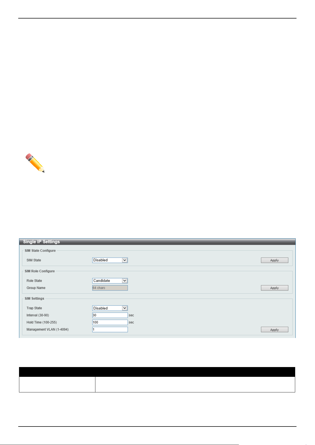
DGS-1520 Series Gigabit Ethernet Smart Managed Switch Web UI Reference Guide
106
There are some instances where pre-saved MS Switches cannot be rediscovered. For example, if the Switch is still
powered down, if it has become the member of another group, or if it has been configured to be a Commander Switch,
the rediscovery process cannot occur.
The topology map now includes new features for connections that are a member of a port trunking group. It will
display the speed and number of Ethernet connections creating this port trunk group.
This version will support Switch upload and downloads for firmware, configuration files, and log files, as follows:
• Firmware - The Switch now supports MS firmware downloads from a TFTP server.
• Configuration Files - This Switch now supports the downloading and uploading of configuration files both to
(for configuration restoration) and from (for configuration backup) MSs, using a TFTP server.
• Log - The Switch now supports uploading MS log files to a TFTP server.
The user may zoom in and zoom out when utilizing the topology window to get a better, more defined view of the
configuration.
NOTE: When the SIM State is enabled and the Role State of the Switch is Commander, the
Topology, Firmware Upgrade, Configuration File Backup/Restore, and Upload Log File
windows will be available.
Single IP Settings
This window is used to display and configure the SIM settings. The Switch is set as a Candidate (CaS) as the factory
default configuration and Single IP Management is disabled.
To view the following window, click Management > Virtual Stacking (SIM) > Single IP Settings, as shown below:
Figure 4-88 Single IP Settings Window
The fields that can be configured in SIM State Configure are described below:
Parameter Description
SIM State
Select this option to enable or disable the SIM state on the Switch. Select
Disabled to disable SIM on the Switch.
Click the Apply button to accept the changes made.

DGS-1520 Series Gigabit Ethernet Smart Managed Switch Web UI Reference Guide
107
The fields that can be configured in SIM Role Configure are described below:
Parameter Description
Role State
Select to change the SIM role of the Switch. Options to choose from are:
• Candidate - A Candidate Switch (CaS) is not the member of a SIM group
but is connected to a Commander Switch.
• Commander - Select to make the Switch a Commander Switch (CS). The
user may join other Switches to this Switch, over Ethernet, to be part of the
SIM group. Choosing this option will also enable the Switch to be configured
for SIM.
By default, the Candidate option is used.
Group Name
Enter a group name. This is optional. This name is used to segment Switches into
different SIM groups.
Click the Apply button to accept the changes made.
The fields that can be configured in SIM Settings are described below:
Parameter Description
Trap State
Select to enable or disable the SIM trap state here.
Interval
Enter the interval in seconds. The range is from 30 to 90.
Hold Time
Enter the hold-time in seconds. The range is from 100 to 255.
Management VLAN
Enter the single IP management message VLAN ID.
Click the Apply button to accept the changes made.
After enabling the Switch to be a Commander Switch (CS), the Single IP Management folder will then contain four
added links to aid in configuring SIM through the Web UI, including Topology, Firmware Upgrade, Configuration
File Backup/Restore, and Upload Log File.
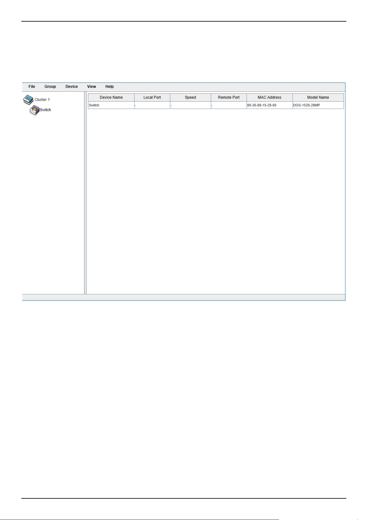
DGS-1520 Series Gigabit Ethernet Smart Managed Switch Web UI Reference Guide
108
Topology
This window is used to view, manage, and configure the Switch within the SIM group and requires Java script to
function properly on your computer.
To view the following window, click Management > Virtual Stacking (SIM) > Topology, as shown below:
Figure 4-89 Topology Window
There is a menu bar at the top of the window containing File, Group, Device, View, and Help.
File
Print Topology
Select this option to print the SIM topology map to any of the printers configured on the PC accessing the Web UI.
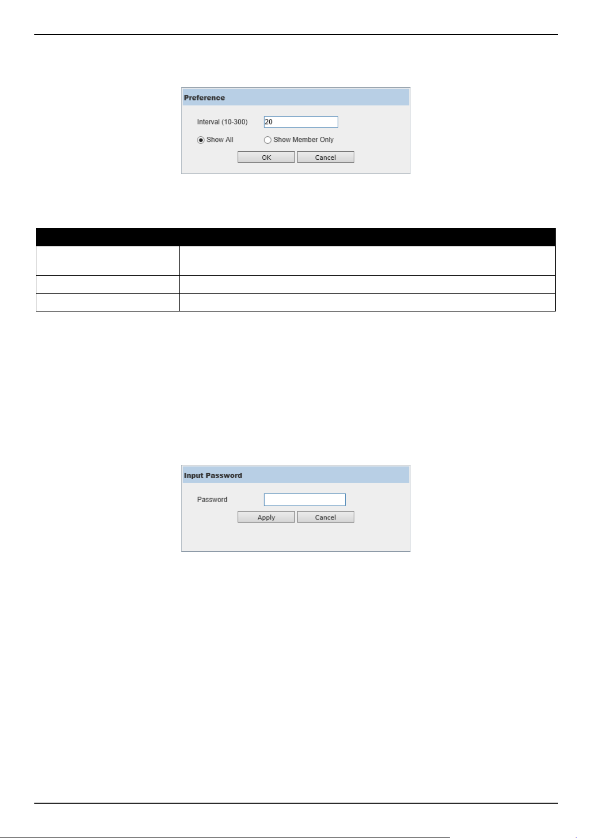
DGS-1520 Series Gigabit Ethernet Smart Managed Switch Web UI Reference Guide
109
Preference
Select this option to configure the display properties for the SIM topology map.
Figure 4-90 Preference
The fields that can be configured are described below:
Parameter Description
Interval
Enter the SIM topology display refresh interval value here. The range is from 10 to
300.
Show All
Select this option to display all available SIM devices in the topology.
Show Member Only
Select this option to only display SIM member devices in the topology.
Click the OK button to accept the changes made.
Click the Cancel button to discard the changes made.
Group
Add to Group
Select a Candidate Switch (CaS) from the list and then select this option (Add to Group) to add the selected CaS to
the SIM group. Password authentication is required when a CaS is added to the SIM group.
Figure 4-91 Add to Group (Input Password)
Enter the Password and click the Apply button to add the CaS to the SIM group.
Click the Cancel button to discard the addition and return to the Topology window.
Remove from Group
Select a Member Switch (MS) from the list and then select this option (Remove from Group) to remove the selected
MS from the SIM group.
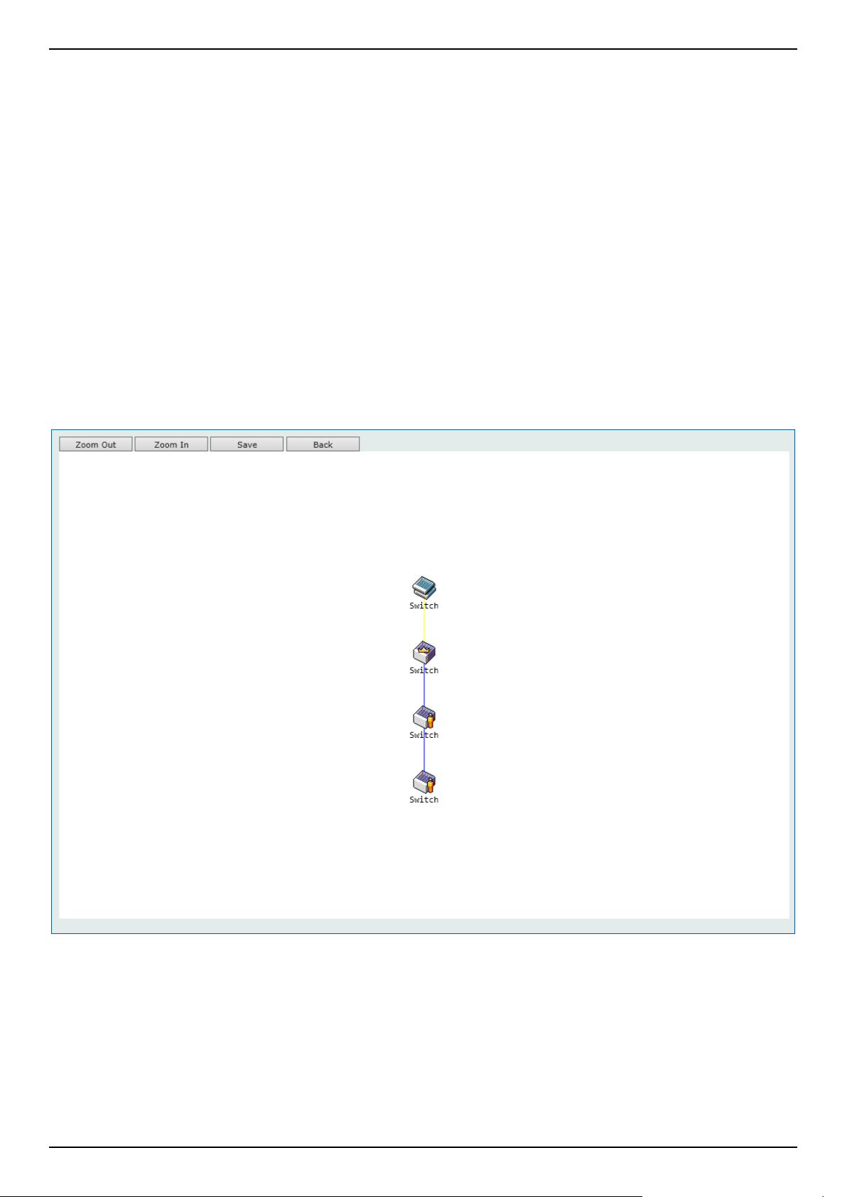
DGS-1520 Series Gigabit Ethernet Smart Managed Switch Web UI Reference Guide
110
Device
Configure
Select a device from the list and then select this option (Configure) to connect to the Web User Interface (if available)
on the selected device.
View
Refresh
Select this option to refresh the items displayed in the page.
Topology
Under View, select Topology to view the following:
Figure 4-92 View > Topology
Click the Zoom In button enlarge the size of the displayed items.
Click the Zoom Out button reduce the size of the displayed items.
Click the Save button to save the display.
Click the Back button to return to the previous window.
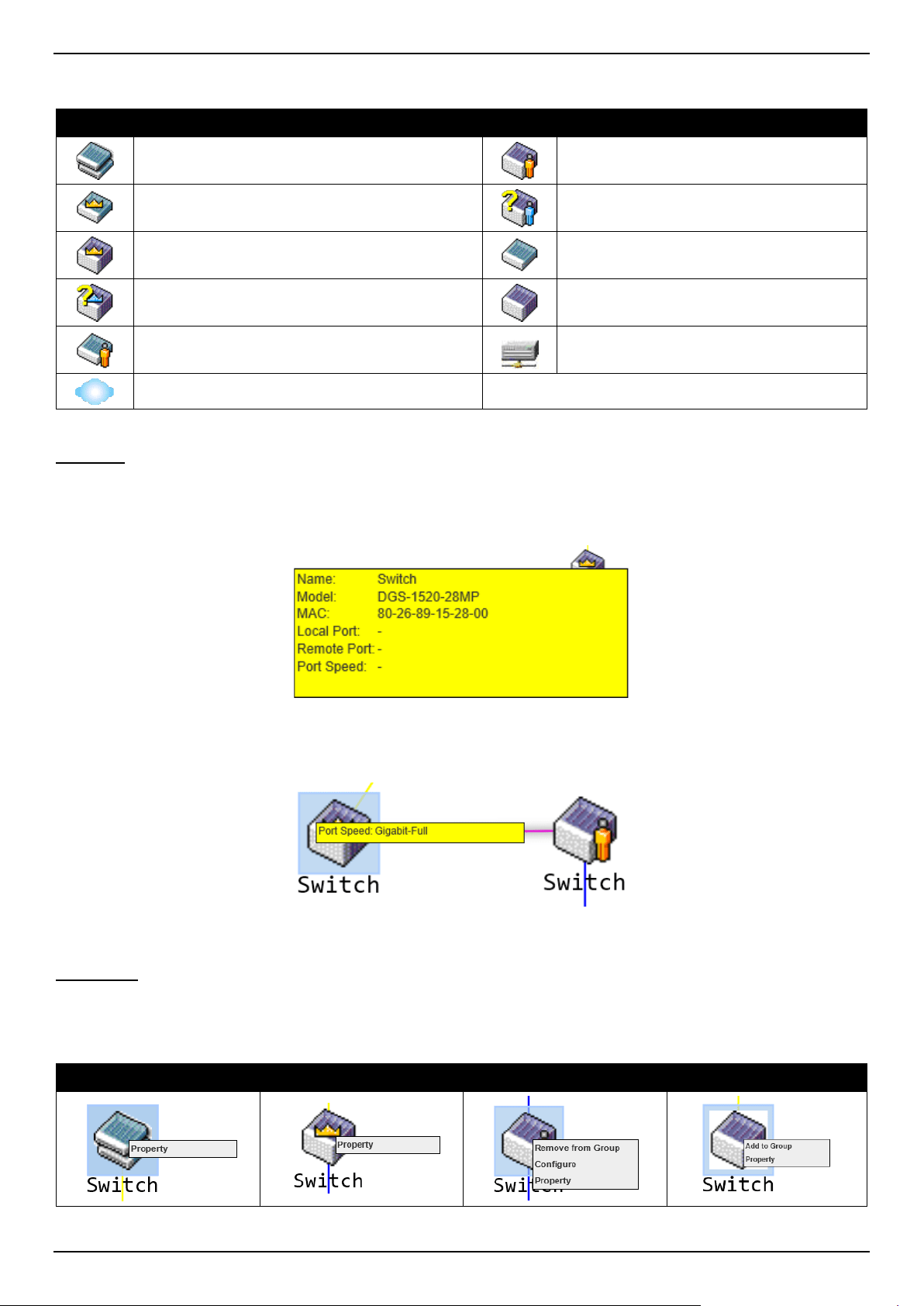
DGS-1520 Series Gigabit Ethernet Smart Managed Switch Web UI Reference Guide
111
This window will display how the devices within the SIM Group connect to other groups and devices. Possible icons
on this window are as follows:
Icon Description Icon Description
Group
Layer 3 Member Switch
Layer 2 Commander Switch
Member Switch of other group
Layer 3 Commander Switch
Layer 2 Candidate Switch
Commander Switch of other group
Layer 3 Candidate Switch
Layer 2 Member Switch
Unknown device
Non-SIM devices
Tool Tips
In the Topology view window, the mouse plays an important role in configuration and in viewing device information.
Hover the mouse pointer over a specific device in the Topology window to display more information about the device
Figure 4-93 Device Information Utilizing the Tool Tip
Hover the mouse pointer over a line between two devices to display the connection speed between the two devices.
Figure 4-94 Port Speed Utilizing the Tool Tip
Right-Click
Right-click on a device to allow the user to perform various functions, depending on the role of the Switch in the SIM
group and the icon associated with it.
Group Commander Switch Member Switch Candidate Switch
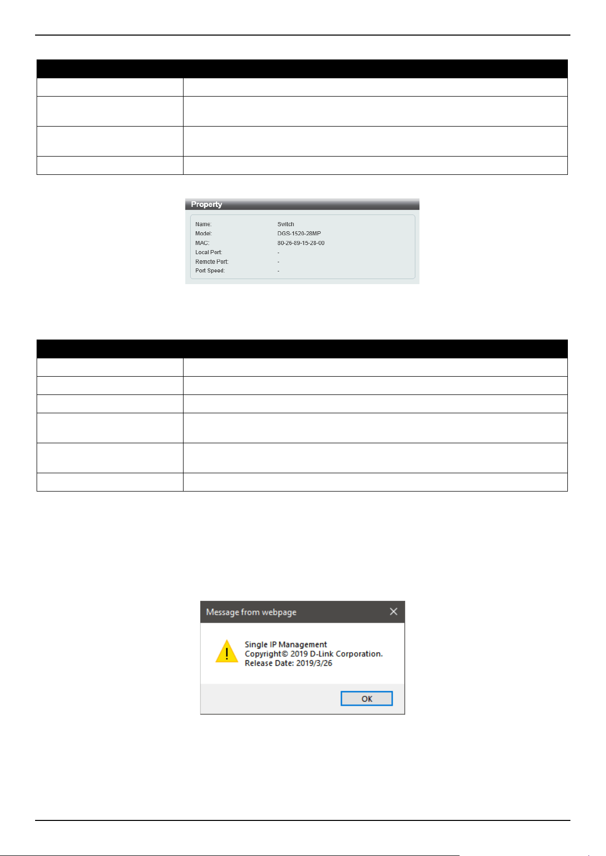
DGS-1520 Series Gigabit Ethernet Smart Managed Switch Web UI Reference Guide
112
The fields that can be configured are described below:
Parameter Description
Property
Specifies to display more information about the device.
Configure
(Member Switch Only) Specifies to connect to the Web User Interface (if available)
on the selected device.
Add to Group
(Candidate Switch Only) Specifies to add the selected CaS to the SIM group.
Password authentication is required when a CaS is added to the SIM group.
Remove from Group
(Member Switch Only) Specifies to remove the selected MS from the SIM group.
Figure 4-95 Property
The fields displayed are described below:
Parameter Description
Name
Displays the device name of the Switch in the SIM group.
Module
Displays the full module name of the Switch.
MAC Address
Displays the MAC address of the Switch.
Local Port
Displays the number of the physical port on the CS that the MS or CaS is
connected to. The CS will have no entry in this field.
Remote Port
Displays the number of the physical port on the MS or CaS that the CS is
connected to. The CS will have no entry in this field.
Port Speed
Displays the connection speed between the CS and the MS or CaS.
Help
About
Select this option to display the SIM Copyright information and release date.
Figure 4-96 About Window
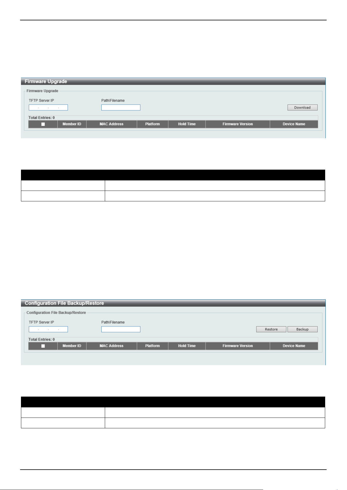
DGS-1520 Series Gigabit Ethernet Smart Managed Switch Web UI Reference Guide
113
Firmware Upgrade
This window is used to view and upgrade firmware from the Commander Switch to the Member Switch. Member
Switches will be listed in the table.
To view the following window, click Management > Virtual Stacking (SIM) > Firmware Upgrade, as shown below:
Figure 4-97 Firmware Upgrade Window
The fields that can be configured are described below:
Parameter Description
TFTP Server IP
Enter the TFTP server IP address.
Path \ Filename
Enter the path and file name.
Click the Download button to update the firmware.
To specify a certain Switch for firmware download, tick its corresponding check box.
Configuration File Backup/Restore
This window is used to view and upgrade configuration files from the Commander Switch to the Member Switch using
a TFTP server. Member Switches will be listed in the table.
To view the following window, click Management > Virtual Stacking (SIM) > Configuration File Backup/Restore,
as shown below:
Figure 4-98 Configuration File Backup/Restore Window
The fields that can be configured are described below:
Parameter Description
TFTP Server IP
Enter the TFTP server IP address.
Path \ Filename
Enter the path and file name.
Click the Restore button to update the configuration from a TFTP server to the member Switch.
Click the Backup button to back up the configuration file to a TFTP server.
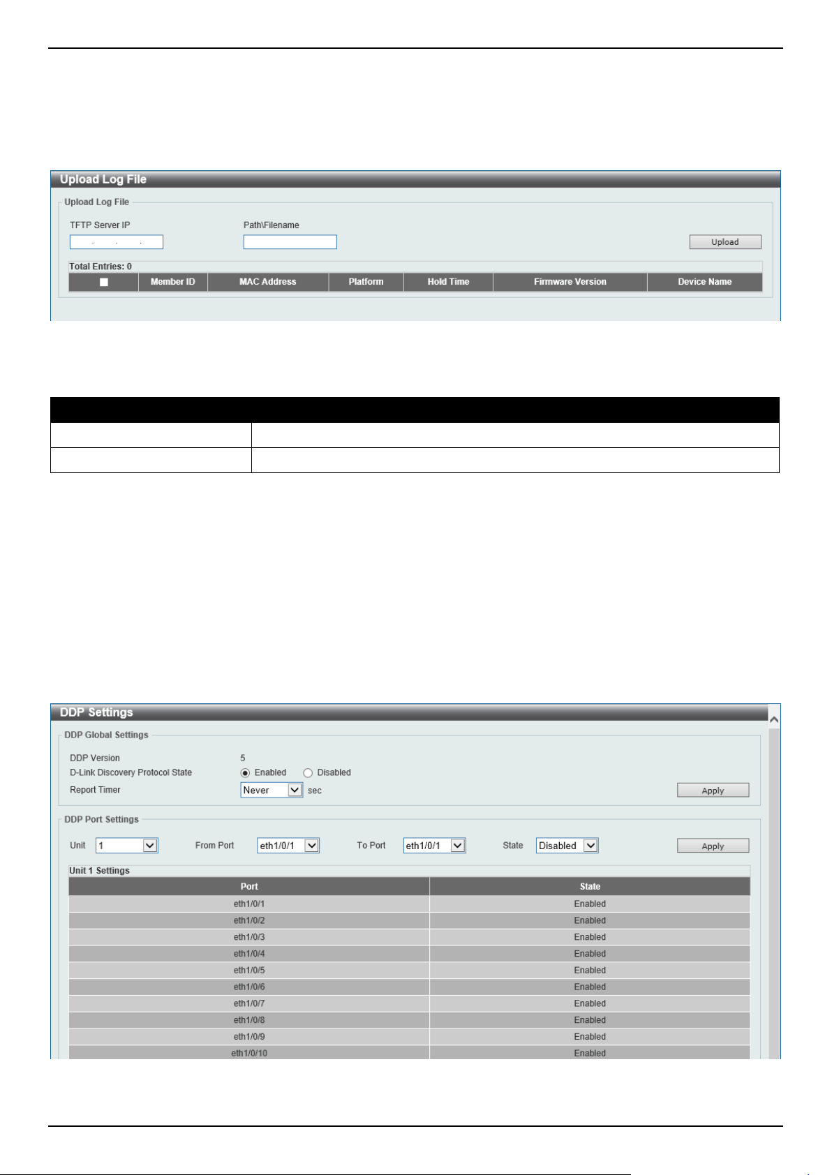
DGS-1520 Series Gigabit Ethernet Smart Managed Switch Web UI Reference Guide
114
Upload Log File
This window is used to view and upload log files from SIM member Switches to a specified PC.
To view the following window, click Management > Virtual Stacking (SIM) > Upload Log File, as shown below:
Figure 4-99 Upload Log File Window
The fields that can be configured are described below:
Parameter Description
TFTP Server IP
Enter the TFTP server IP address.
Path \ Filename
Enter the path and file name.
Click the Upload button to initiate the file transfer.
D-Link Discovery Protocol
DDP Settings
This window is used to display and configure the D-Link Discovery Protocol (DDP) settings.
To view the following window, click Management > D-Link Discovery Protocol > DDP Settings, as shown below:
Figure 4-100 DDP Settings Window
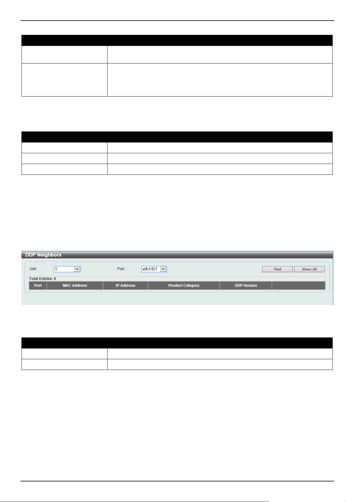
DGS-1520 Series Gigabit Ethernet Smart Managed Switch Web UI Reference Guide
115
The fields that can be configured in DDP Global Settings are described below:
Parameter Description
D-Link Discovery Protocol
State
Select to globally enable or disable the DDP feature here.
Report Timer
Select the report timer value here. This is used to configure interval between two
consecutive DDP report messages. Options to choose from are 30, 60, 90, 120
seconds, or Never.
Selecting Never instructs the Switch to stop sending report messages.
Click the Apply button to accept the changes made.
The fields that can be configured in DDP Port Settings are described below:
Parameter Description
Unit
Select the Switch unit that will be used for this configuration here.
From Port - To Port
Select the range of ports that will be used for this configuration here.
State
Select to enable or disable the DDP feature on the specified port(s) here.
Click the Apply button to accept the changes made.
DDP Neighbors
This window is used to display the DDP neighbors.
To view the following window, click Management > D-Link Discovery Protocol > DDP Neighbors, as shown below:
Figure 4-101 DDP Neighbors Window
The fields that can be configured are described below:
Parameter Description
Unit
Select the Switch unit that will be used here.
Port
Select the port that will be used here.
Click the Find button to display the DDP neighbors connecting through the specified port.
Click the Show All button to display all DDP neighbors connecting to and through the Switch.
Click the Show Detail button to view detailed information associated with the entry.
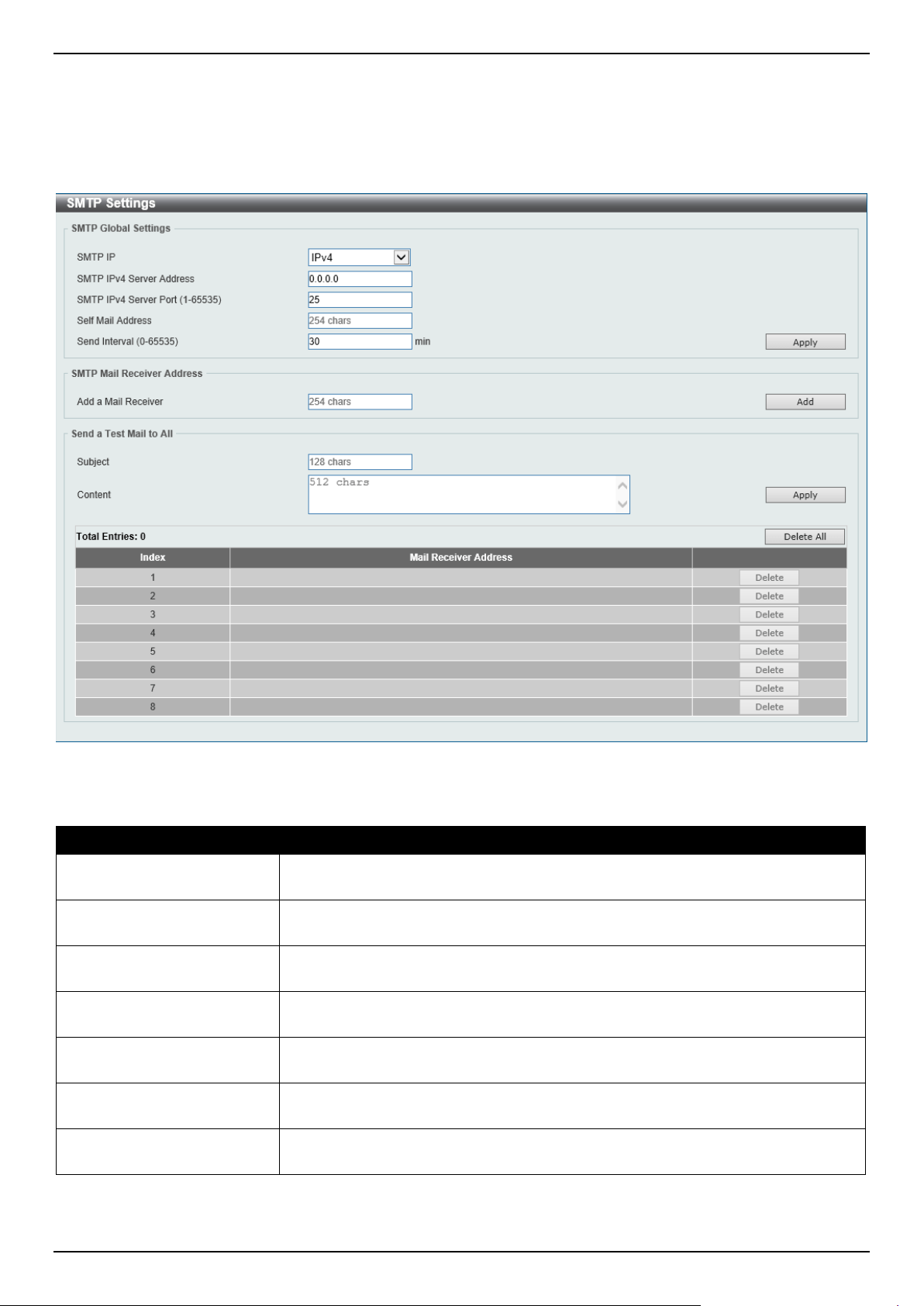
DGS-1520 Series Gigabit Ethernet Smart Managed Switch Web UI Reference Guide
116
SMTP Settings
This window is used to display and configure the Simple Mail Transfer Protocol (SMTP) settings.
To view the following window, click Management > SMTP Settings, as shown below:
Figure 4-102 SMTP Settings Window
The fields that can be configured in SMTP Global Settings are described below:
Parameter Description
SMTP IP Select the SMTP server IP address type here. Options to choose from are IPv4
and IPv6.
SMTP IPv4 Server Address After selecting IPv4 as the SMTP IP type, enter the SMTP server IPv4 address
here.
SMTP IPv6 Server Address After selecting IPv6 as the SMTP IP type, enter the SMTP server IPv6 address
here.
SMTP IPv4 Server Port After selecting IPv4 as the SMTP IP type, enter the SMTP server port number
here. The range is from 1 to 65535. By default, this value is 25.
SMTP IPv6 Server Port After selecting IPv6 as the SMTP IP type, enter the SMTP server port number
here. The range is from 1 to 65535. By default, this value is 25.
Self Mail Address
Enter the email address that represents the Switch here. This string can be up to
254 characters long.
Send Interval
Enter the sending interval value here. The range is from 0 to 65535 minutes. By
default, this value is 30 minutes.
Click the Apply button to accept the changes made.

DGS-1520 Series Gigabit Ethernet Smart Managed Switch Web UI Reference Guide
117
The fields that can be configured in SMTP Mail Receiver Address are described below:
Parameter Description
Add a Mail Receiver
Enter the email address of the receiver here. This string can be up to 254
characters long.
Click the Add button to add a new SMTP email recipient.
The fields that can be configured in Send a Test Mail to All are described below:
Parameter Description
Subject
Enter the subject of the email here. This string can be up to 128 characters long.
Content
Enter the content of the email here. This string can be up to 512 characters long.
Click the Apply button to accept the changes made.
Click the Delete All button to delete all the entries found in the display table.
Click the Delete button to delete the specified entry.
NLB FDB Settings
This window is used to display and configure the Network Load Balancing (NLB) FDB settings. The NLB function is
used to support the Microsoft server load balancing application where multiple servers can share the same IP address
and MAC address. The requests from clients will be forwarded to all the servers, but will only be processed by one of
them. The server can work in two different modes:
• Unicast mode: The client uses a unicast MAC address as the destination MAC address to reach the server.
• Multicast mode: The client uses a multicast MAC address as the destination MAC address to reach the server.
This destination MAC address is called the shared MAC address. However, the server uses its own MAC address
(rather than the shared MAC address) as the source MAC address in the reply packet. In other words, a NLB unicast
address is usually not the source MAC address of a packet.
When the received packet contains a destination MAC address that matches the configured unicast MAC address, it
will be forwarded to those configured ports, regardless of the VLAN membership configuration.
Administrators cannot configure a static address of the MAC address table as a NLB address. However, if a MAC
address is created as a NLB MAC address entry, the same MAC address can be still dynamically learnt in the Layer 2
MAC address table. In this situation, the NLB has higher priority; the dynamically learnt FDB entry won't take effect.
NOTE: Link Aggregation cannot be configured across multiple Switch units in the stack when the
NLB feature is enabled.
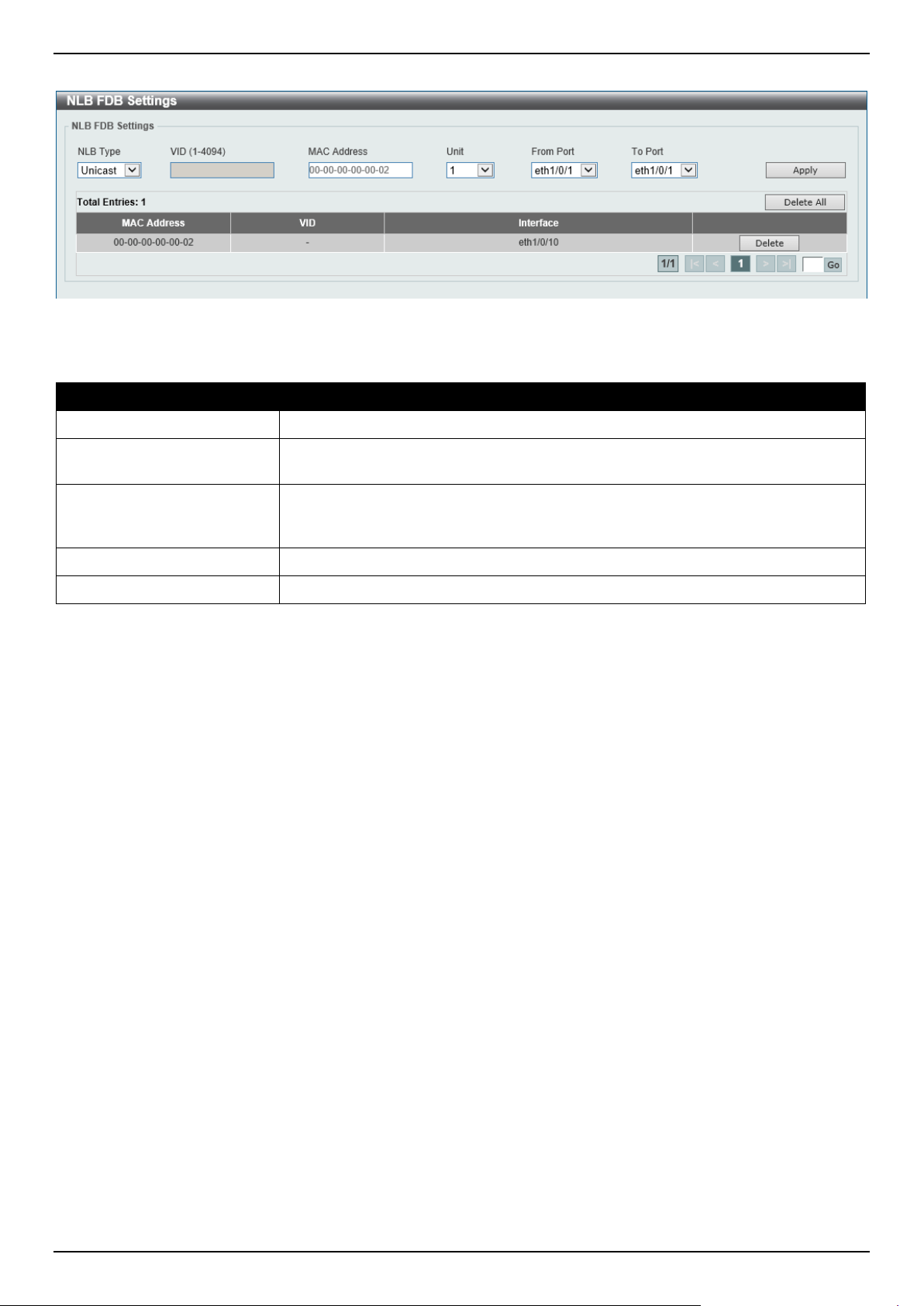
DGS-1520 Series Gigabit Ethernet Smart Managed Switch Web UI Reference Guide
118
To view the following window, click Management > NLB FDB Settings, as shown below:
Figure 4-103 NLB FDB Settings Window
The fields that can be configured are described below:
Parameter Description
NLB Type Select the NLB type here. Options to choose from are Unicast and Multicast.
VID After selecting Multicast as the NLB type, enter the VLAN ID used in this
configuration here.
MAC Address
Enter the unicast or multicast MAC address of the entry here. If a received packet
contains a destination MAC address that matches the specified MAC address, it
will be forwarded to the specified interface.
Unit
Select the Switch unit ID that will be used here.
From Port - To Port
Select the port range that will be used here.
Click the Apply button to accept the changes made.
Click the Delete All button to delete all the entries found in the display table.
Click the Delete button to delete the specified entry.
Enter a page number and click the Go button to navigate to a specific page when multiple pages exist.
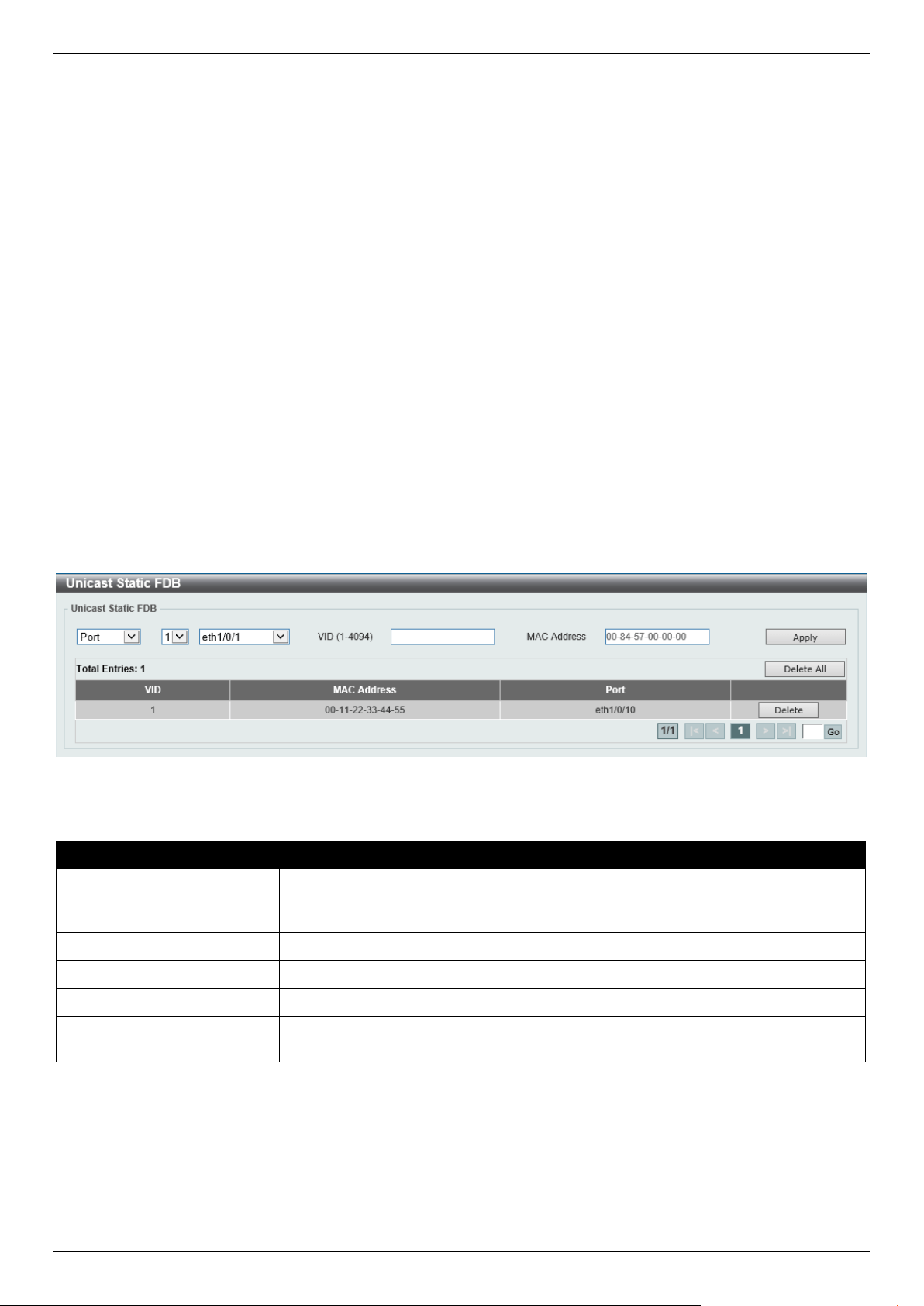
DGS-1520 Series Gigabit Ethernet Smart Managed Switch Web UI Reference Guide
119
5. Layer 2 Features
FDB
VLAN
VLAN Tunnel
STP
ERPS (G.8032)
Loopback Detection
Link Aggregation
L2 Protocol Tunnel
L2 Multicast Control
LLDP
FDB
Static FDB
Unicast Static FDB
This window is used to display and configure the static unicast forwarding settings on the Switch.
To view the following window, click L2 Features > FDB > Static FDB > Unicast Static FDB, as shown below:
Figure 5-1 Unicast Static FDB Window
The fields that can be configured are described below:
Parameter Description
Port/Drop
Allows the selection of the port number on which the MAC address entered
resides. This option could also drop the MAC address from the unicast static FDB.
Select the port number when selecting the Port.
Unit
Select the stacking unit ID of the Switch that will be configured here.
Port Number After selecting the Port option, select the port number used here.
VID
Enter the VLAN ID on which the associated unicast MAC address resides.
MAC Address
Enter the MAC address to which packets will be statically forwarded. This must be
a unicast MAC address.
Click the Apply button to accept the changes made.
Click the Delete All button to delete all the entries found in the display table.
Click the Delete button to delete the specified entry.
Enter a page number and click the Go button to navigate to a specific page when multiple pages exist.
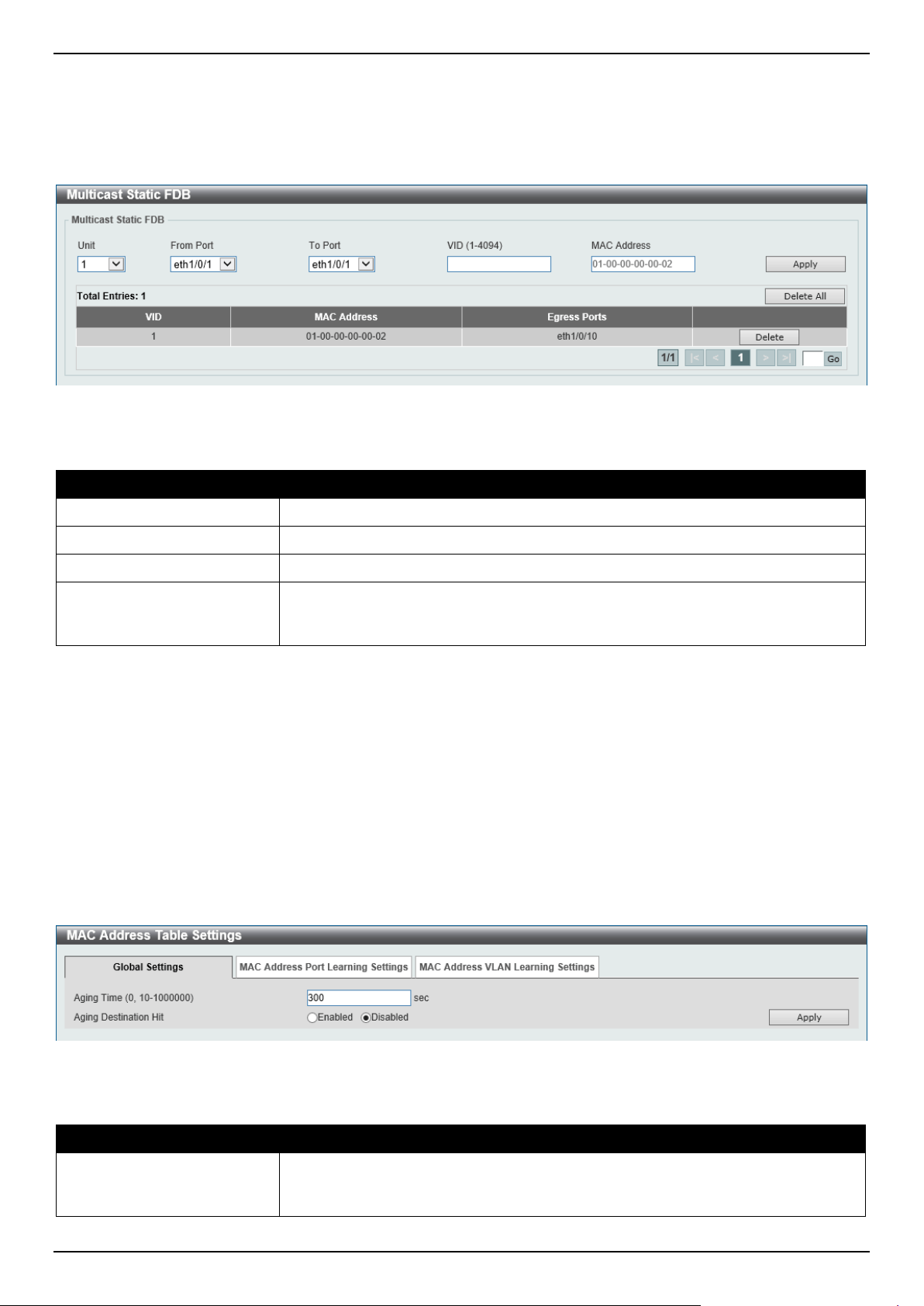
DGS-1520 Series Gigabit Ethernet Smart Managed Switch Web UI Reference Guide
120
Multicast Static FDB
This window is used to display and configure the multicast static FDB settings.
To view the following window, click L2 Features > FDB > Static FDB > Multicast Static FDB, as shown below:
Figure 5-2 Multicast Static FDB Window
The fields that can be configured are described below:
Parameter Description
Unit
Select the stacking unit ID of the Switch that will be configured here.
From Port - To Port
Select the range of ports that will be used for this configuration here.
VID
Enter the VLAN ID of the VLAN the corresponding MAC address belongs to.
MAC Address
Enter the static destination MAC address of the multicast packets. This must be a
multicast MAC address. The format of the destination MAC address is 01-XX-XX-
XX-XX-XX.
Click the Apply button to accept the changes made.
Click the Delete All button to remove all the entries.
Click the Delete button to remove the specific entry.
Enter a page number and click the Go button to navigate to a specific page when multiple pages exist.
MAC Address Table Settings
This window is used to display and configure the global MAC address table settings.
To view the following window, click L2 Features > FDB > MAC Address Table Settings, as shown below:
Figure 5-3 MAC Address Table Settings (Global Settings) Window
The fields that can be configured are described below:
Parameter Description
Aging Time
Enter the MAC address table aging time here. This value must be between 10 and
1000000 seconds. Entering 0 will disable MAC address aging. By default, this
value is 300 seconds.
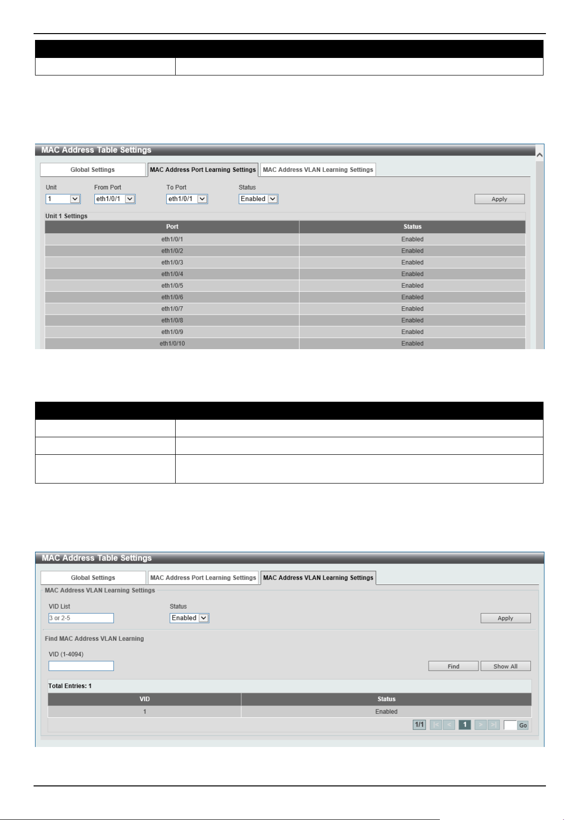
DGS-1520 Series Gigabit Ethernet Smart Managed Switch Web UI Reference Guide
121
Parameter Description
Aging Destination Hit
Select to enable or disable the aging destination hit function.
Click the Apply button to accept the changes made.
After selecting the MAC Address Port Learning Settings tab option, at the top of the page, the following page will be
available.
Figure 5-4 MAC Address Table Settings (MAC Address Port Learning Settings) Window
The fields that can be configured are described below:
Parameter Description
Unit
Select the stacking unit ID of the Switch that will be configured here.
From Port - To Port
Select the range of ports that will be used for this configuration here.
Status
Select to enable or disable the MAC address learning function on the ports
specified here.
Click the Apply button to accept the changes made.
After selecting the MAC Address VLAN Learning Settings tab option, at the top of the page, the following page will
be available.
Figure 5-5 MAC Address Table Settings (MAC Address VLAN Learning Settings) Window
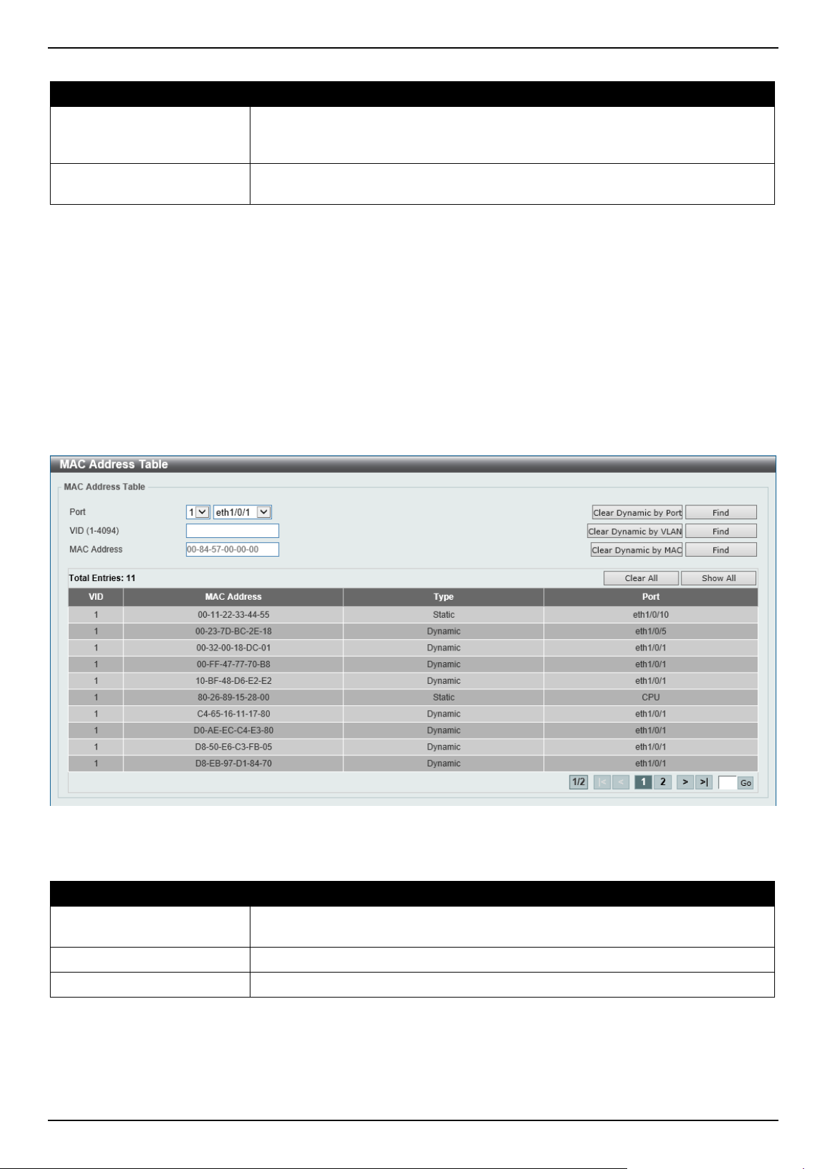
DGS-1520 Series Gigabit Ethernet Smart Managed Switch Web UI Reference Guide
122
The fields that can be configured are described below:
Parameter Description
VID List
Enter the VLAN ID(s) that will be used in this configuration or display here. A
series of VLAN IDs can be entered separated by commas or a range of VLAN IDs
can be entered separated by a hyphen.
Status
Select to enable or disable the MAC address learning function on the VLAN(s)
specified here.
Click the Apply button to accept the changes made.
Click the Find button to locate a specific entry based on the information entered.
Click the Show All button to display all the available entries.
Enter a page number and click the Go button to navigate to a specific page when multiple pages exist.
MAC Address Table
This window is used to view the entries listed in the MAC address table.
To view the following window, click L2 Features > FDB > MAC Address Table, as shown below:
Figure 5-6 MAC Address Table Window
The fields that can be configured are described below:
Parameter Description
Port
Select the stacking unit ID and the port number of the Switch that will be
configured here.
VID
Enter the VLAN ID that will be used for this configuration here.
MAC Address
Enter the MAC address that will be used for this configuration here.
Click the Clear Dynamic by Port button to clear the dynamic MAC address listed on the corresponding port.
Click the Clear Dynamic by VLAN button to clear the dynamic MAC address listed on the corresponding VLAN.
Click the Clear Dynamic by MAC button to clear the dynamic MAC address entered.
Click the Find button to locate a specific entry based on the information entered.
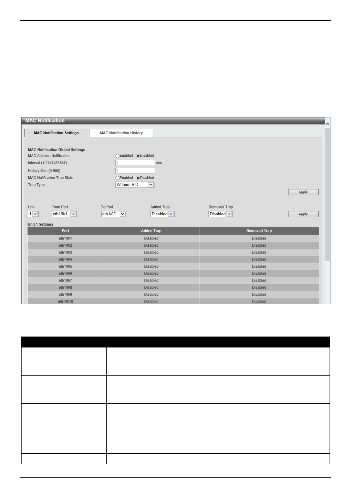
DGS-1520 Series Gigabit Ethernet Smart Managed Switch Web UI Reference Guide
123
Click the Clear All button to clear all dynamic MAC addresses.
Click the Show All button to display all the MAC addresses recorded in the MAC address table.
Enter a page number and click the Go button to navigate to a specific page when multiple pages exist.
MAC Notification
This window is used to display and configure MAC notification.
To view the following window, click L2 Features > FDB > MAC Notification, as shown below:
Figure 5-7 MAC Notification (MAC Notification Settings) Window
The fields that can be configured are described below:
Parameter Description
MAC Address Notification
Select to enable or disable MAC notification globally on the Switch
Interval
Enter the time value between notifications. This value must be between 1 and
2147483647 seconds. By default, this value is 1 second.
History Size
Enter the maximum number of entries listed in the history log used for notification.
This value must be between 0 and 500. By default, this value is 1.
MAC Notification Trap State
Select to enable or disable the MAC notification trap state.
Trap Type
Select the trap type here. Options to choose from are:
• Without VID - Specifies the trap information without the VLAN ID.
• With VID - Specifies the trap information with the VLAN ID.
Unit
Select the stacking unit ID of the Switch that will be configured here.
From Port - To Port
Select the range of ports that will be used for this configuration here.
Added Trap
Select to enable or disable the added trap for the port(s) selected.
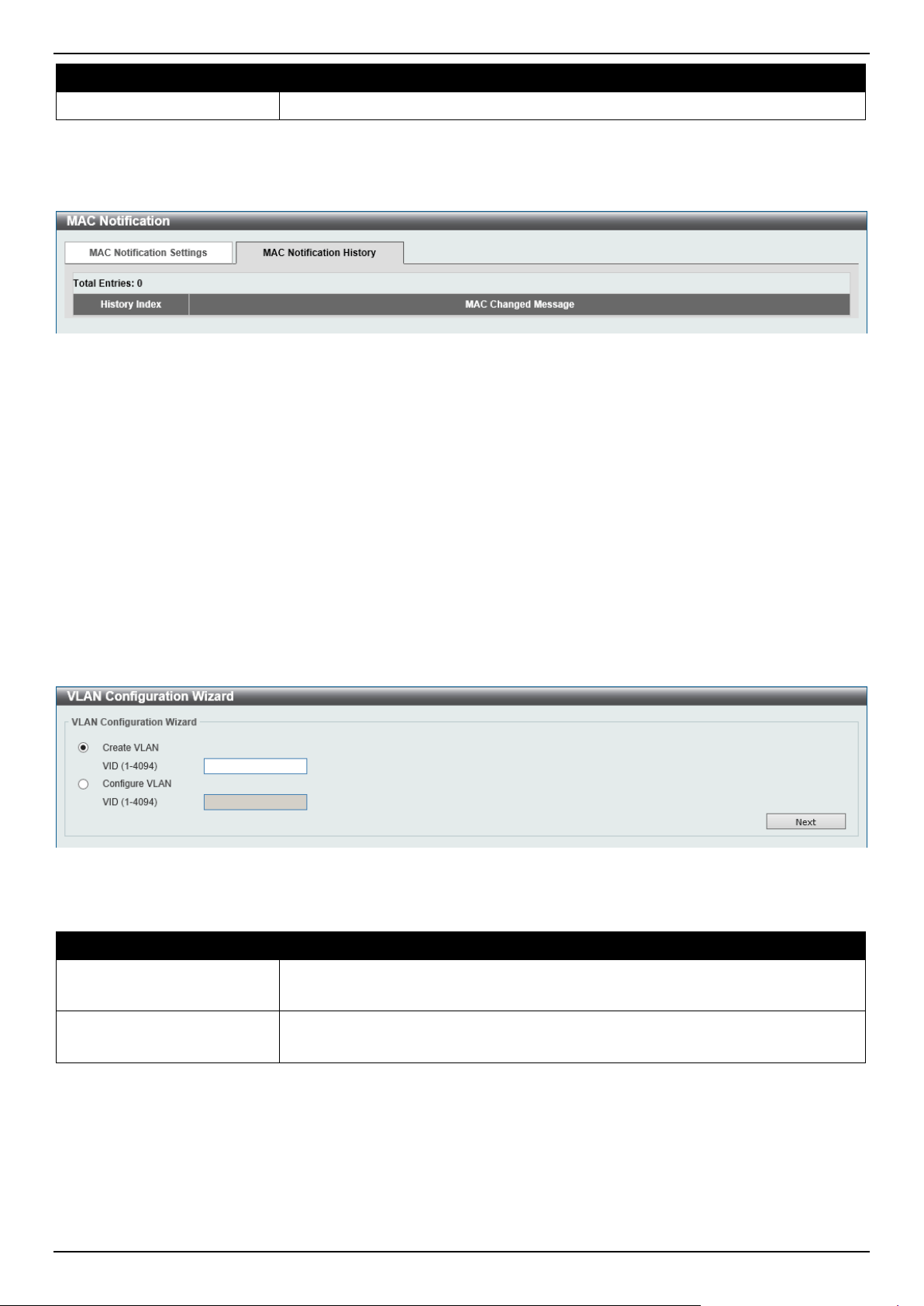
DGS-1520 Series Gigabit Ethernet Smart Managed Switch Web UI Reference Guide
124
Parameter Description
Removed Trap
Select to enable or disable the removed trap for the port(s) selected.
Click the Apply button to accept the changes made for each individual section.
After selecting the MAC Notification History tab, at the top of the page, the following page will be available.
Figure 5-8 MAC Notification (MAC Notification History) Window
On this page, a list of MAC notification messages will be displayed.
VLAN
VLAN Configuration Wizard
This window is used to start the VLAN configuration wizard.
Create/Configure VLAN
To view the following window, click L2 Features > VLAN > VLAN Configuration Wizard, as shown below:
Figure 5-9 VLAN Configuration Wizard (Step 1) Window
The fields that can be configured are described below:
Parameter Description
Create VLAN
Select this option to create a new VLAN.
• VID - Enter the VLAN ID here. The range is from 1 to 4094.
Configure VLAN
Select this option to configure an existing VLAN.
• VID - Enter the VLAN ID here. The range is from 1 to 4094.
Click the Next button to continue to the next step.
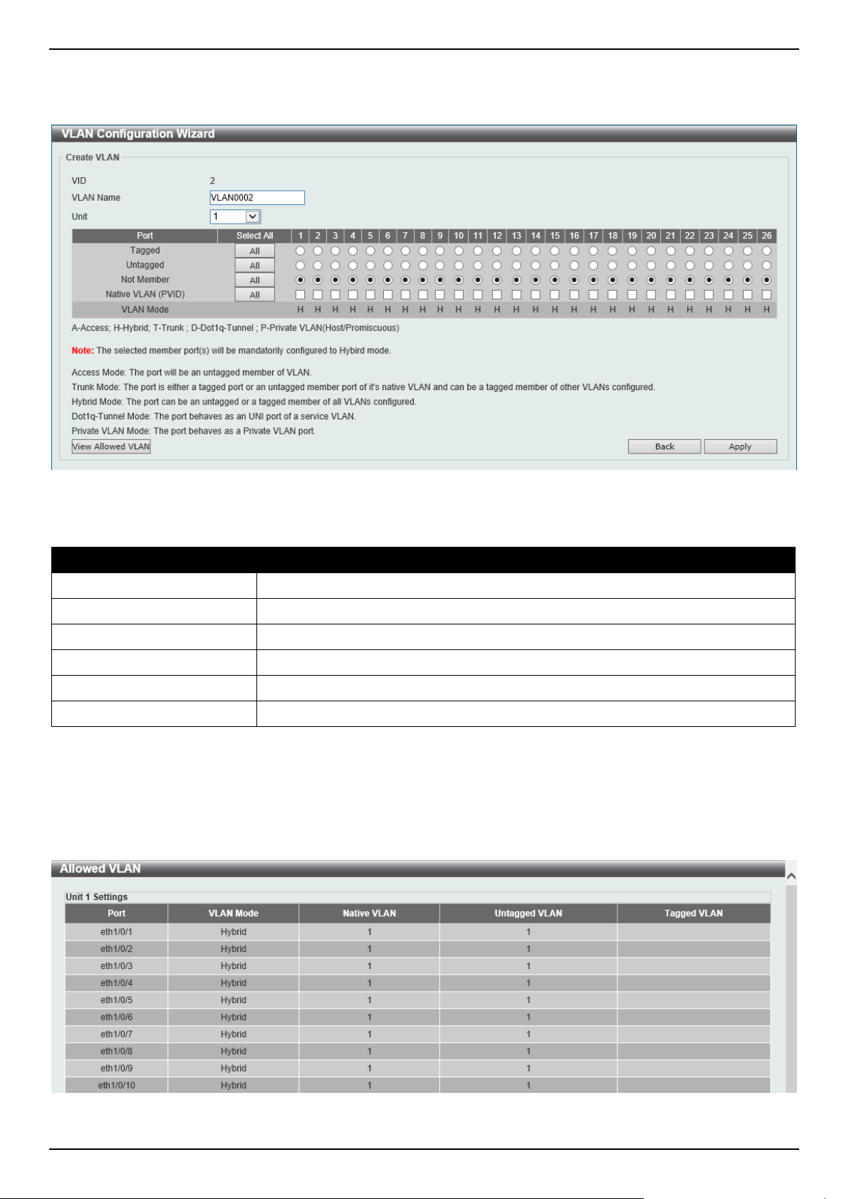
DGS-1520 Series Gigabit Ethernet Smart Managed Switch Web UI Reference Guide
125
Create VLAN
After selecting the Create VLAN option and clicking the Next button, the following window will appear.
Figure 5-10 VLAN Configuration Wizard (Create VLAN) Window
The fields that can be configured are described below:
Parameter Description
VLAN Name
Enter the name for the VLAN here.
Unit
Select the Switch unit that will be used for this configuration here.
Tagged
Select the switch ports that are tagged members of this VLAN here.
Untagged
Select the switch ports that are untagged members of this VLAN here.
Not Member
Select the switch ports that are not members of this VLAN here.
Native VLAN (PVID)
Select the switch ports that support the native VLAN here.
Click the View Allowed VLAN button view the allowed VLAN settings.
Click the Back button to return to the previous step.
Click the Apply button to accept the changes made.
After clicking the View Allowed VLAN button, the following window will appear.
Figure 5-11 Allowed VLAN Window
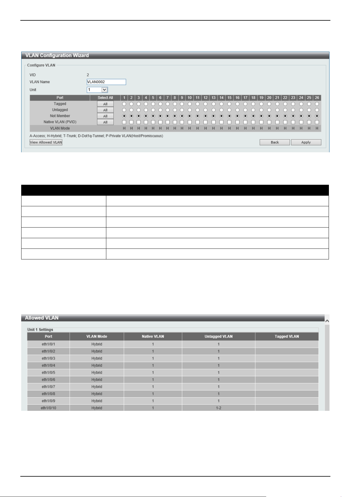
DGS-1520 Series Gigabit Ethernet Smart Managed Switch Web UI Reference Guide
126
Configure VLAN
After selecting the Configure VLAN option and clicking the Next button, the following window will appear.
Figure 5-12 VLAN Configuration Wizard (Configure VLAN) Window
The fields that can be configured are described below:
Parameter Description
VLAN Name
Enter the name for the VLAN here.
Unit
Select the Switch unit that will be used for this configuration here.
Tagged
Select the switch ports that are tagged members of this VLAN here.
Untagged
Select the switch ports that are untagged members of this VLAN here.
Not Member
Select the switch ports that are not members of this VLAN here.
Native VLAN (PVID)
Select the switch ports that support the native VLAN here.
Click the View Allowed VLAN button view the allowed VLAN settings.
Click the Back button to return to the previous step.
Click the Apply button to accept the changes made.
After clicking the View Allowed VLAN button, the following window will appear.
Figure 5-13 Allowed VLAN Window
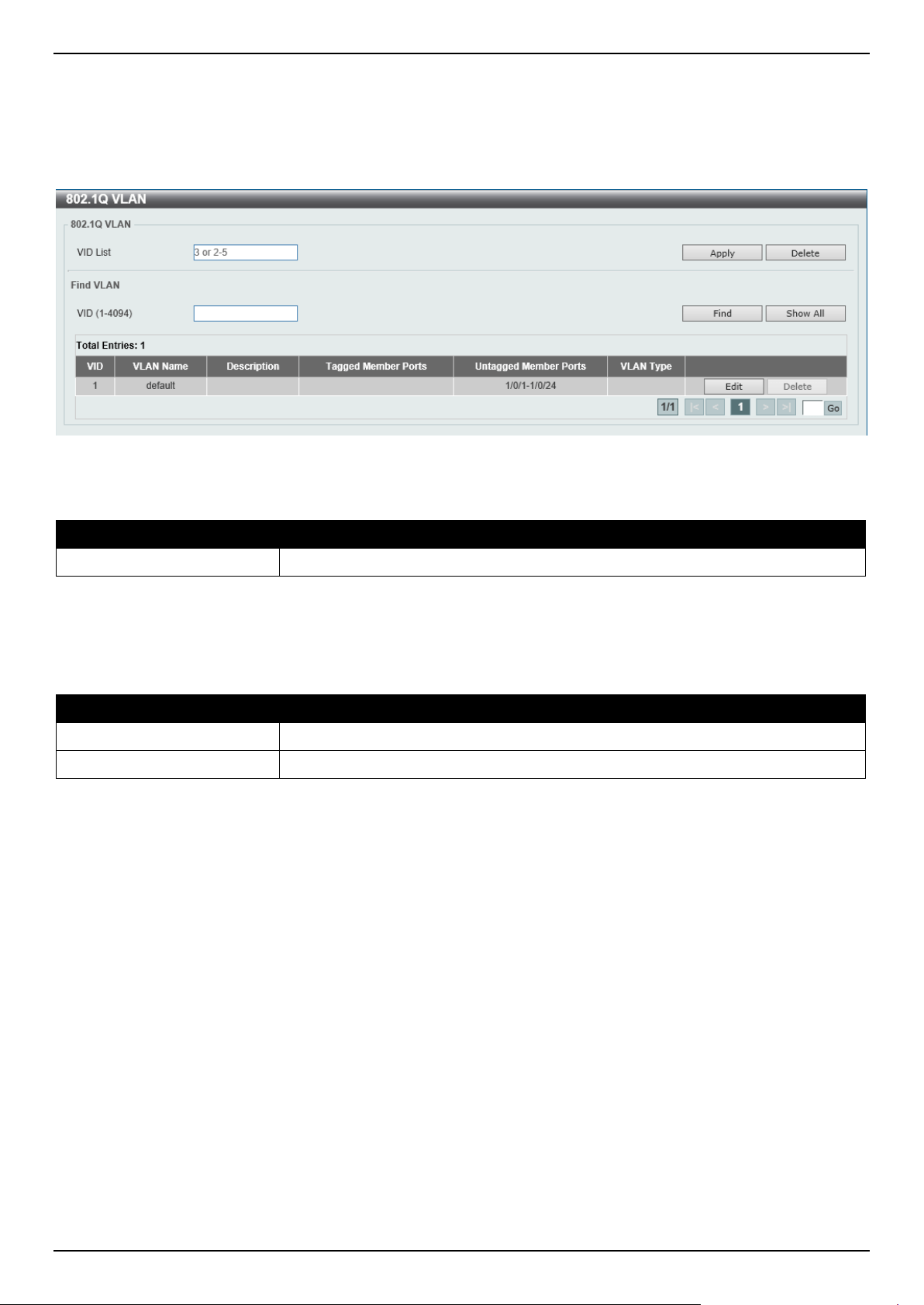
DGS-1520 Series Gigabit Ethernet Smart Managed Switch Web UI Reference Guide
127
802.1Q VLAN
This window is used to display and configure the VLAN settings on this Switch.
To view the following window, click L2 Features > VLAN > 802.1Q VLAN, as shown below:
Figure 5-14 802.1Q VLAN Window
The fields that can be configured in 802.1Q VLAN are described below:
Parameter Description
VID List
Enter the VLAN ID list that will be created here.
Click the Apply button to create a new 802.1Q VLAN.
Click the Delete button to remove the 802.1Q VLAN specified.
The fields that can be configured in Find VLAN are described below:
Parameter Description
VID
Enter the VLAN ID that will be displayed here.
VLAN Name After clicking the Edit button, enter the name of the VLAN here.
Click the Find button to locate a specific entry based on the information entered.
Click the Show All button to locate all the entries.
Click the Edit button to re-configure the specific entry.
Click the Delete button to remove the specific entry.
Enter a page number and click the Go button to navigate to a specific page when multiple pages exist.
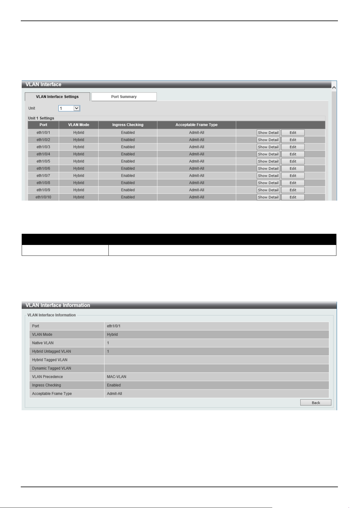
DGS-1520 Series Gigabit Ethernet Smart Managed Switch Web UI Reference Guide
128
VLAN Interface
This window is used to display and configure the VLAN interface settings.
To view the following window, click L2 Features > VLAN > VLAN Interface and select the VLAN Interface Settings
tab, as shown below:
Figure 5-15 VLAN Interface Settings Window
The fields that can be configured are described below:
Parameter Description
Unit
Select the Switch unit that will be used for this configuration here.
Click the Show Detail button to view detailed information about the VLAN on the specific interface.
Click the Edit button to re-configure the specific entry.
After clicking the Show Detail button, the following page will appear.
Figure 5-16 VLAN Interface (VLAN Detail) Window
On this page, detailed information about the VLAN of the specific interface is displayed.
Click the Back button to return to the previous page.
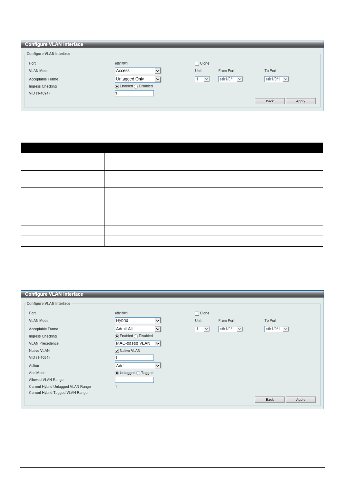
DGS-1520 Series Gigabit Ethernet Smart Managed Switch Web UI Reference Guide
129
After click the Edit button, the following page will appear. This is a dynamic page that will change when a different
VLAN Mode is selected. When Access was selected as the VLAN Mode, the following page will appear.
Figure 5-17 VLAN Interface (Access) Window
The fields that can be configured are described below:
Parameter Description
VLAN Mode Select the VLAN mode option here. Options to choose from are Access, Hybrid,
Trunk, Dot1q-Tunnel, Promiscuous, and Host.
Acceptable Frame
Select the acceptable frame behavior option here. Options to choose from are
Tagged Only, Untagged Only, and Admit All.
Ingress Checking
Select to enable or disable the ingress checking function.
VLAN ID
Enter the VLAN ID used for this configuration here. This value must be between 1
and 4094.
Clone
Select this option to enable the clone feature.
Unit
Select the unit ID of the Switch in the stack here.
From Port - To Port
Select the range of ports that will be used in the clone feature here.
Click the Apply button to accept the changes made.
Click the Back button to discard the changes made and return to the previous page.
When Hybrid was selected as the VLAN Mode, the following page will appear.
Figure 5-18 VLAN Interface (Hybrid) Window
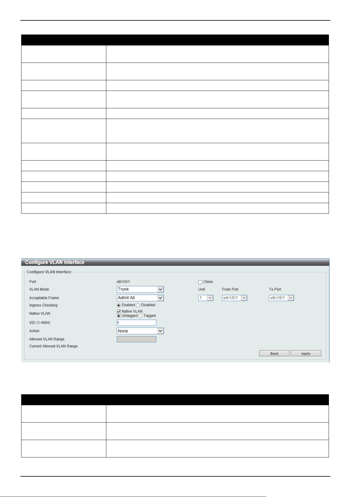
DGS-1520 Series Gigabit Ethernet Smart Managed Switch Web UI Reference Guide
130
The fields that can be configured are described below:
Parameter Description
VLAN Mode Select the VLAN mode option here. Options to choose from are Access, Hybrid,
Trunk, Dot1q-Tunnel, Promiscuous, and Host.
Acceptable Frame
Select the acceptable frame behavior option here. Options to choose from are
Tagged Only, Untagged Only, and Admit All.
Ingress Checking
Select to enable or disable the ingress checking function.
VLAN Precedence Select the VLAN precedence option here. Options to choose from are Mac-based
VLAN and Subnet-based VLAN.
Native VLAN
Tick this option to enable the native VLAN function.
VID After ticking the Native VLAN option, the following parameter will be available.
Enter the VLAN ID used for this configuration here. This value must be between 1
and 4094.
Action Select the action that will be taken here. Options to choose from are Add,
Remove, Tagged, and Untagged.
Add Mode Select whether to add an Untagged or Tagged parameters.
Allowed VLAN Range
Enter the allowed VLAN range here.
Clone
Select this option to enable the clone feature.
Unit
Select the unit ID of the Switch in the stack here.
From Port - To Port
Select the range of ports that will be used in the clone feature here.
Click the Apply button to accept the changes made.
Click the Back button to discard the changes made and return to the previous page.
When Trunk was selected as the VLAN Mode, the following page will appear.
Figure 5-19 VLAN Interface (Trunk) Window
The fields that can be configured are described below:
Parameter Description
VLAN Mode Select the VLAN mode option here. Options to choose from are Access, Hybrid,
Trunk, Dot1q-Tunnel, Promiscuous, and Host.
Acceptable Frame
Select the acceptable frame behavior option here. Options to choose from are
Tagged Only, Untagged Only, and Admit All.
Ingress Checking After selecting Trunk as the VLAN Mode, the following parameter will be
available. Select to enable or disable the ingress checking function.
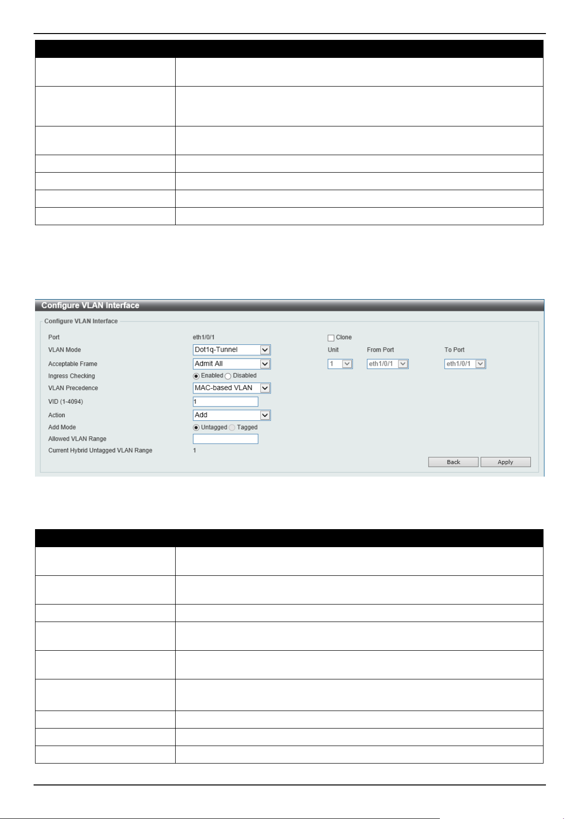
DGS-1520 Series Gigabit Ethernet Smart Managed Switch Web UI Reference Guide
131
Parameter Description
Native VLAN
Tick this option to enable the native VLAN function. Also, select if this VLAN
supports Untagged or Tagged frames.
VID After ticking the Native VLAN option, the following parameter will be available.
Enter the VLAN ID used for this configuration here. This value must be between 1
and 4094.
Action Select the action that will be taken here. Options to choose from are All, Add,
Remove, Except, and Replace.
Allowed VLAN Range
Enter the allowed VLAN range here.
Clone
Select this option to enable the clone feature.
Unit
Select the unit ID of the Switch in the stack here.
From Port - To Port
Select the range of ports that will be used in the clone feature here.
Click the Apply button to accept the changes made.
Click the Back button to discard the changes made and return to the previous page.
When Dot1q-Tunnel was selected as the VLAN Mode, the following page will appear.
Figure 5-20 VLAN Interface (802.1Q-Tunnel) Window
The fields that can be configured are described below:
Parameter Description
VLAN Mode Select the VLAN mode option here. Options to choose from are Access, Hybrid,
Trunk, Dot1q-Tunnel, Promiscuous, and Host.
Acceptable Frame
Select the acceptable frame behavior option here. Options to choose from are
Tagged Only, Untagged Only, and Admit All.
Ingress Checking
Select to enable or disable the ingress checking function.
VLAN Precedence Select the VLAN precedence option here. Options to choose from are Mac-based
VLAN and Subnet-based VLAN.
VID
Enter the VLAN ID used for this configuration here. This value must be between 1
and 4094.
Action Select Add to add a new entry based in the information entered.
Select Remove to remove an entry based in the information entered.
Add Mode Select to add an Untagged parameter.
Allowed VLAN Range
Enter the allowed VLAN range here.
Clone
Select this option to enable the clone feature.
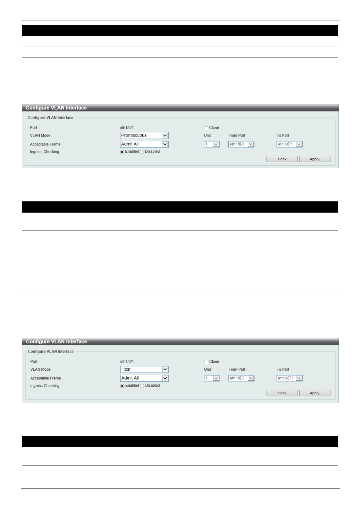
DGS-1520 Series Gigabit Ethernet Smart Managed Switch Web UI Reference Guide
132
Parameter Description
Unit
Select the unit ID of the Switch in the stack here.
From Port - To Port
Select the range of ports that will be used in the clone feature here.
Click the Apply button to accept the changes made.
Click the Back button to discard the changes made and return to the previous page.
When Promiscuous was selected as the VLAN Mode, the following page will appear.
Figure 5-21 VLAN Interface (Promiscuous) Window
The fields that can be configured are described below:
Parameter Description
VLAN Mode Select the VLAN mode option here. Options to choose from are Access, Hybrid,
Trunk, Dot1q-Tunnel, Promiscuous, and Host.
Acceptable Frame
Select the acceptable frame behavior option here. Options to choose from are
Tagged Only, Untagged Only, and Admit All.
Ingress Checking
Select to enable or disable the ingress checking function.
Clone
Select this option to enable the clone feature.
Unit
Select the unit ID of the Switch in the stack here.
From Port - To Port
Select the range of ports that will be used in the clone feature here.
Click the Apply button to accept the changes made.
Click the Back button to discard the changes made and return to the previous page.
When Host was selected as the VLAN Mode, the following page will appear.
Figure 5-22 VLAN Interface (Host) Window
The fields that can be configured are described below:
Parameter Description
VLAN Mode Select the VLAN mode option here. Options to choose from are Access, Hybrid,
Trunk, Dot1q-Tunnel, Promiscuous, and Host.
Acceptable Frame
Select the acceptable frame behavior option here. Options to choose from are
Tagged Only, Untagged Only, and Admit All.
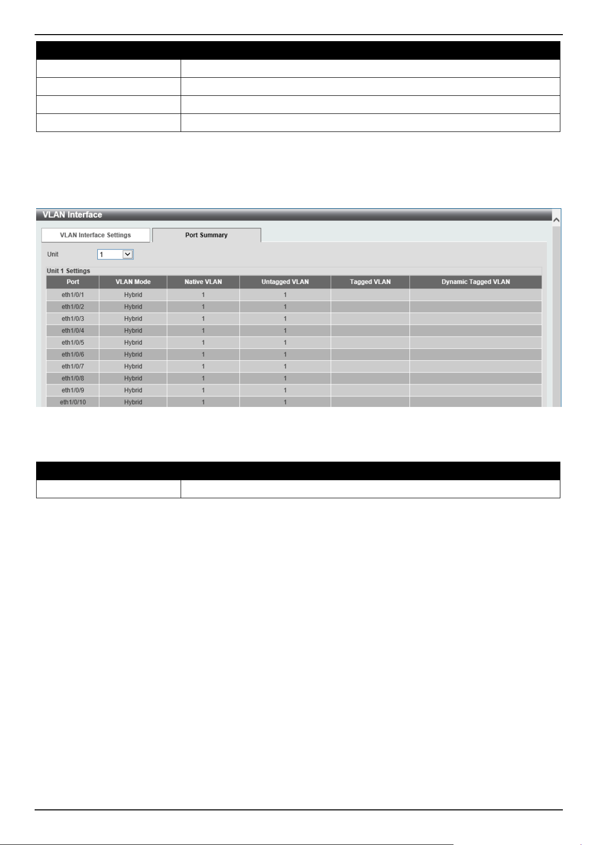
DGS-1520 Series Gigabit Ethernet Smart Managed Switch Web UI Reference Guide
133
Parameter Description
Ingress Checking
Select to enable or disable the ingress checking function.
Clone
Select this option to enable the clone feature.
Unit
Select the unit ID of the Switch in the stack here.
From Port - To Port
Select the range of ports that will be used in the clone feature here.
Click the Apply button to accept the changes made.
Click the Back button to discard the changes made and return to the previous page.
To view the following window, select the Port Summary tab, as shown below:
Figure 5-23 Port Summary Window
The fields that can be configured are described below:
Parameter Description
Unit
Select the Switch unit that will be used for this configuration here.
802.1v Protocol VLAN
Protocol VLAN Profile
This window is used to display and configure 802.1v protocol VLAN profiles. The 802.1v Protocol VLAN group settings
support multiple VLANs for each protocol and allow the user to configure untagged ports of different protocols on the
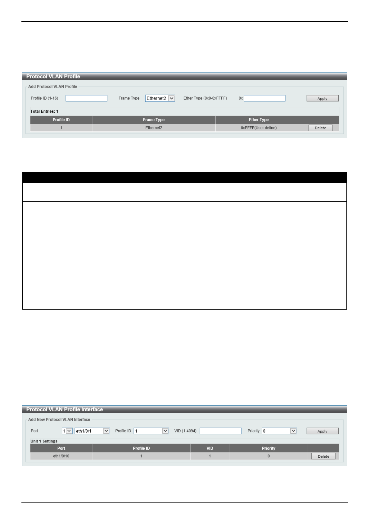
DGS-1520 Series Gigabit Ethernet Smart Managed Switch Web UI Reference Guide
134
same physical port. For example, it allows the user to configure an 802.1Q and 802.1v untagged port on the same
physical port.
To view the following window, click L2 Features > VLAN > 802.1v Protocol VLAN > Protocol VLAN Profile, as
shown below:
Figure 5-24 Protocol VLAN Profile Window
The fields that can be configured are described below:
Parameter Description
Profile ID
Enter the 802.1v protocol VLAN profile ID here. This value must be between 1 and
16.
Frame Type
Select the frame type option here. This function maps packets to protocol-defined
VLANs by examining the type octet within the packet header to discover the type
of protocol associated with it. Options to choose from are Ethernet 2, SNAP, and
LLC.
Ether Type
Enter the Ethernet type value for the group here. The protocol value is used to
identify a protocol of the frame type specified. The range is from 0x0 to 0xFFFF.
Depending on the frame type, the octet string will have one of the following values:
• For Ethernet 2, this is a 16-bit (2-octet) hex value. For example, IPv4 is
0800, IPv6 is 86DD, ARP is 0806, etc.
• For IEEE802.3 SNAP, this is a 16-bit (2-octet) hex value.
• For IEEE802.3 LLC, this is a 2-octet IEEE 802.2 Link Service Access Point
(LSAP) pair. The first octet is for Destination Service Access Point (DSAP)
and the second octet is for Source.
Click the Apply button to accept the changes made.
Click the Delete button to remove the specific entry.
Protocol VLAN Profile Interface
This window is used to display and configure the protocol VLAN profile interface settings.
To view the following window, click L2 Features > VLAN > 802.1v Protocol VLAN > Protocol VLAN Profile
Interface, as shown below:
Figure 5-25 Protocol VLAN Profile Interface Window
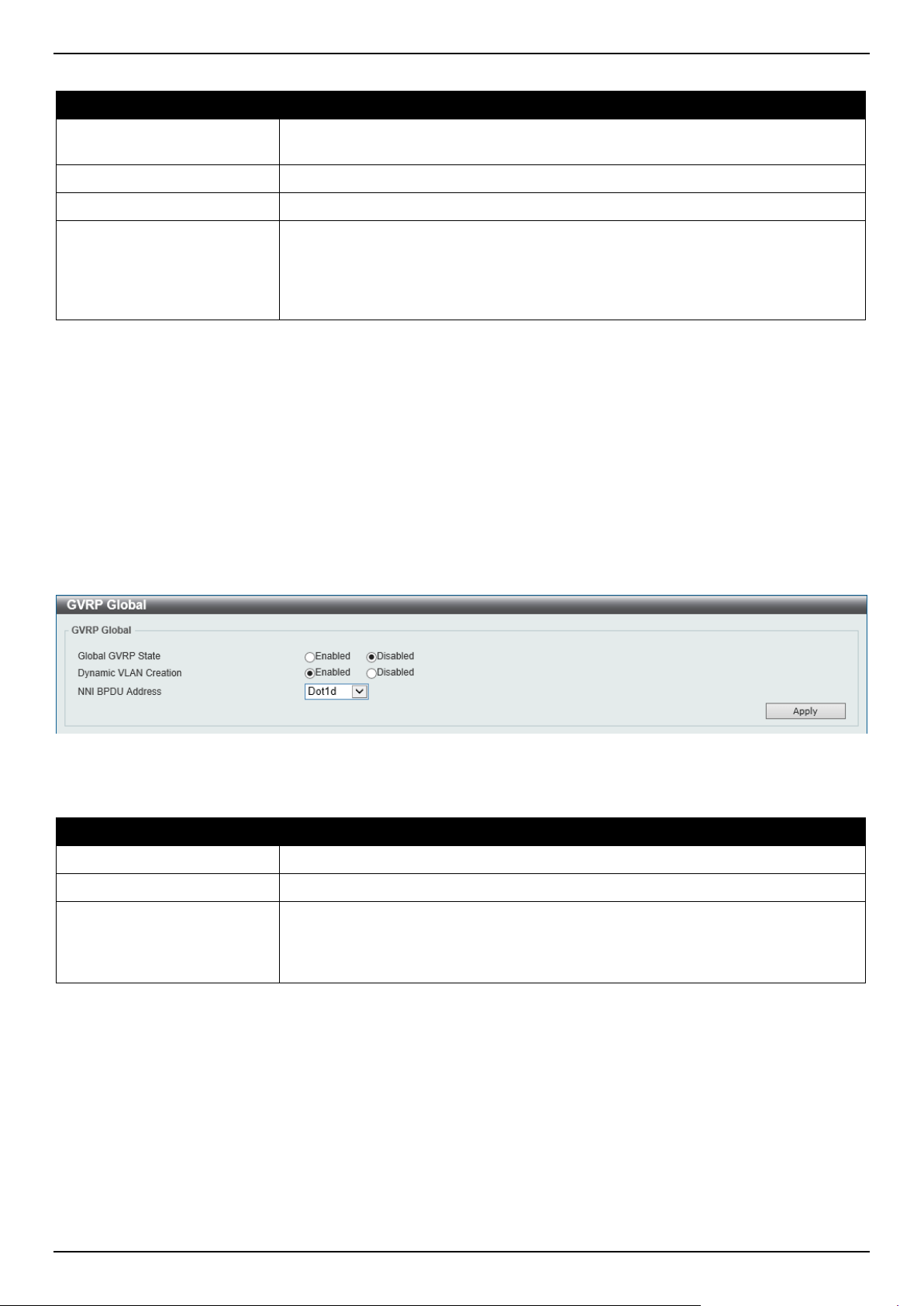
DGS-1520 Series Gigabit Ethernet Smart Managed Switch Web UI Reference Guide
135
The fields that can be configured are described below:
Parameter Description
Port
Select the stacking unit ID and the port number of the Switch that will be
configured here.
Profile ID
Select the 802.1v protocol VLAN profile ID here.
VID
Enter the VLAN ID used here.
Priority
Select the priority value used here. This value is between 0 and 7. This parameter
is specified to rewrite the 802.1p default priority previously set in the Switch, which
is used to determine the CoS queue that packets are forwarded to. Once this field
is specified, packets accepted by the Switch that match this priority are forwarded
to the CoS queue specified previously.
Click the Apply button to accept the changes made.
Click the Delete button to remove the specific entry.
GVRP
GVRP Global
This window is used to display and configure the global GARP VLAN Registration Protocol (GVRP) settings.
To view the following window, click L2 Features > VLAN > GVRP > GVRP Global, as shown below:
Figure 5-26 GVRP Global Window
The fields that can be configured are described below:
Parameter Description
Global GVRP State
Select to enable or disable the global GVRP state here.
Dynamic VLAN Creation
Select to enable or disable the dynamic VLAN creation function here.
NNI BPDU Address
Select the NNI BPDU address option here. This option is used to determine the
BPDU protocol address for GVRP in customer networks. It can use 802.1d GVRP
address or 802.1ad service provider GVRP address. Options to choose from are
Dot1d and Dot1ad.
Click the Apply button to accept the changes made.
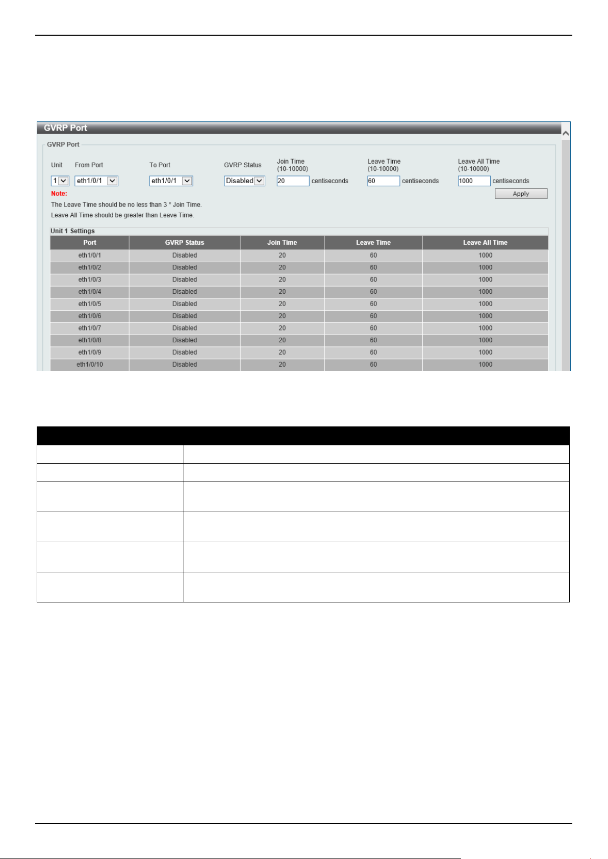
DGS-1520 Series Gigabit Ethernet Smart Managed Switch Web UI Reference Guide
136
GVRP Port
This window is used to display and configure the GVRP port settings.
To view the following window, click L2 Features > VLAN > GVRP > GVRP Port, as shown below:
Figure 5-27 GVRP Port Window
The fields that can be configured are described below:
Parameter Description
Unit
Select the Switch unit that will be used for this configuration here.
From Port - To Port
Select the range of ports that will be used for this configuration here.
GVRP Status
Select the enable or disable the GVRP port status. This enables the port to
dynamically become a member of a VLAN. By default, this option is disabled.
Join Time
Enter the Join Time value in centiseconds. This value must be between 10 and
10000 centiseconds. By default, this value is 20 centiseconds.
Leave Time
Enter the Leave Time value in centiseconds. This value must be between 10 and
10000 centiseconds. By default, this value is 60 centiseconds.
Leave All Time
Enter the Leave All Time value in centiseconds. This value must be between 10
and 10000 centiseconds. By default, this value is 1000 centiseconds.
Click the Apply button to accept the changes made.

DGS-1520 Series Gigabit Ethernet Smart Managed Switch Web UI Reference Guide
137
GVRP Advertise VLAN
This window is used to display and configure the GVRP Advertise VLAN settings.
To view the following window, click L2 Features > VLAN > GVRP > GVRP Advertise VLAN, as shown below:
Figure 5-28 GVRP Advertise VLAN Window
The fields that can be configured are described below:
Parameter Description
Unit
Select the Switch unit that will be used for this configuration here.
From Port - To Port
Select the range of ports that will be used for this configuration here.
Action
Select the advertised VLAN to port mapping action here. Options to choose from
are All, Add, Remove, and Replace.
When selecting All, all the advertised VLANs will be used.
Advertise VID List
Enter the advertised VLAN ID list here.
Click the Apply button to accept the changes made.
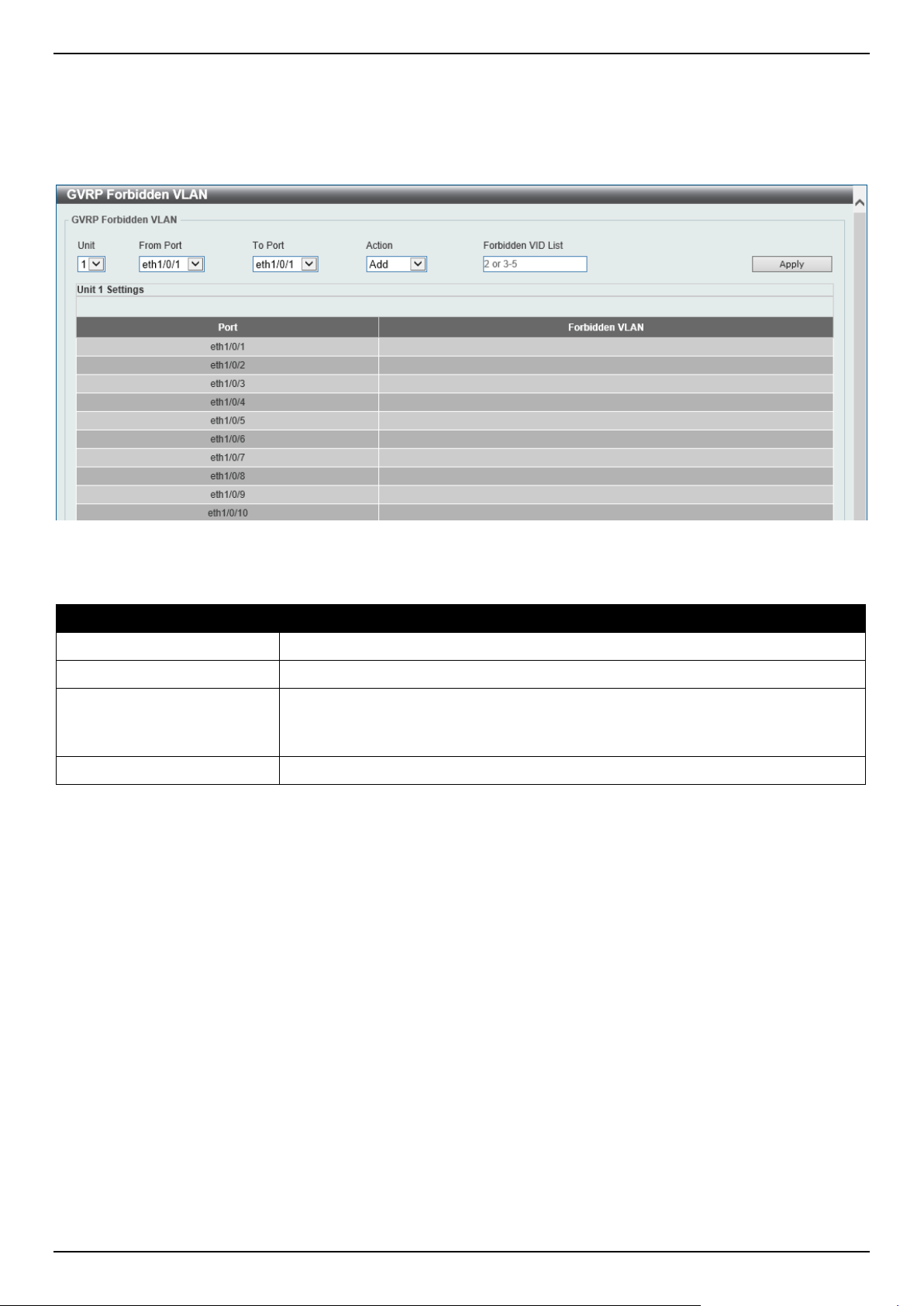
DGS-1520 Series Gigabit Ethernet Smart Managed Switch Web UI Reference Guide
138
GVRP Forbidden VLAN
This window is used to display and configure the GVRP forbidden VLAN settings.
To view the following window, click L2 Features > VLAN > GVRP > GVRP Forbidden VLAN, as shown below:
Figure 5-29 GVRP Forbidden VLAN Window
The fields that can be configured are described below:
Parameter Description
Unit
Select the Switch unit that will be used for this configuration here.
From Port - To Port
Select the range of ports that will be used for this configuration here.
Action
Select the forbidden VLAN to port mapping action that will be taken here. Options
to choose from are All, Add, Remove, and Replace.
When selecting All, all the forbidden VLANs will be used.
Forbidden VID List
Enter the forbidden VLAN ID list here.
Click the Apply button to accept the changes made.
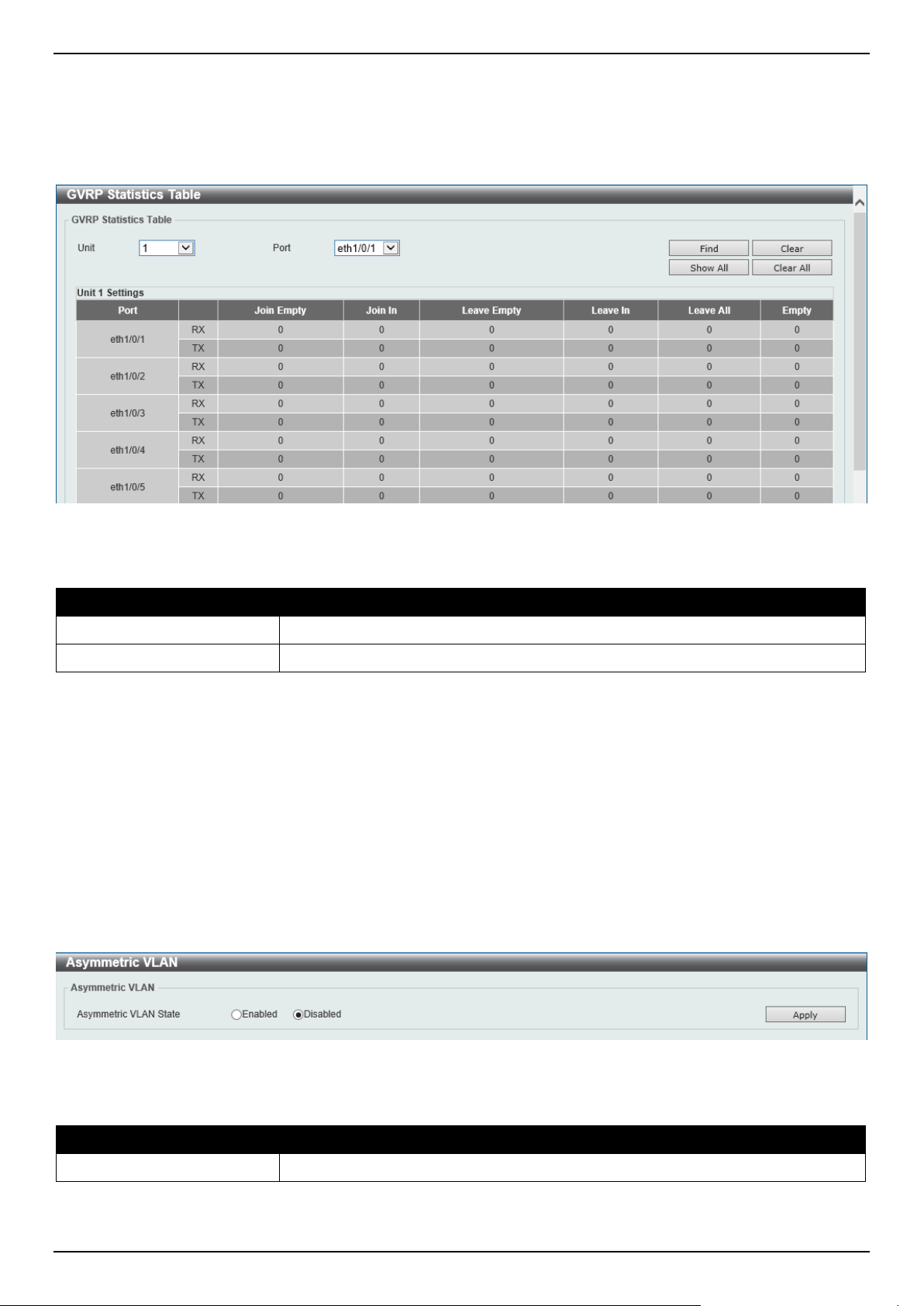
DGS-1520 Series Gigabit Ethernet Smart Managed Switch Web UI Reference Guide
139
GVRP Statistics Table
This window is used to view GVRP statistics information.
To view the following window, click L2 Features > VLAN > GVRP > GVRP Statistics Table, as shown below:
Figure 5-30 GVRP Statistics Table Window
The fields that can be configured are described below:
Parameter Description
Unit
Select the Switch unit to be displayed here.
Port
Select the port number to display GVRP statistic information for here.
Click the Find button to locate a specific entry based on the information entered.
Click the Clear button to clear all the information for the specific port.
Click the Show All button to view all GVRP statistic information.
Click the Clear All button to clear all the information in this table.
Asymmetric VLAN
This window is used to display and configure the asymmetric VLAN settings.
To view the following window, click L2 Features > VLAN > Asymmetric VLAN, as shown below:
Figure 5-31 Asymmetric VLAN Window
The fields that can be configured are described below:
Parameter Description
Asymmetric VLAN State
Select to enable or disable the asymmetric VLAN feature here.
Click the Apply button to accept the changes made.
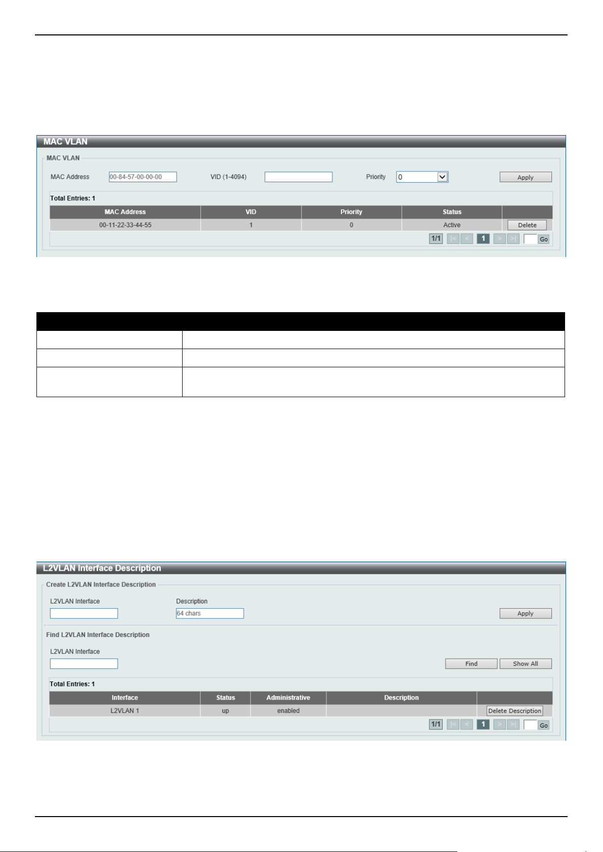
DGS-1520 Series Gigabit Ethernet Smart Managed Switch Web UI Reference Guide
140
MAC VLAN
This window is used to display and configure the MAC-based VLAN information. When a static MAC-based VLAN
entry is configured, the VLAN operating on the port will be changed.
To view the following window, click L2 Features > VLAN > MAC VLAN, as shown below:
Figure 5-32 MAC VLAN Window
The fields that can be configured are described below:
Parameter Description
MAC Address
Enter the unicast MAC address.
VID
Enter the VLAN ID that will be used.
Priority
Select the priority that is assigned to untagged packets. This value is between 0
and 7.
Click the Apply button to accept the changes made.
Click the Delete button to remove the specific entry.
Enter a page number and click the Go button to navigate to a specific page when multiple pages exist.
L2VLAN Interface Description
This window is used to display and configure the Layer 2 VLAN interface description.
To view the following window, click L2 Features > VLAN > L2VLAN Interface Description, as shown below:
Figure 5-33 L2VLAN Interface Description Window
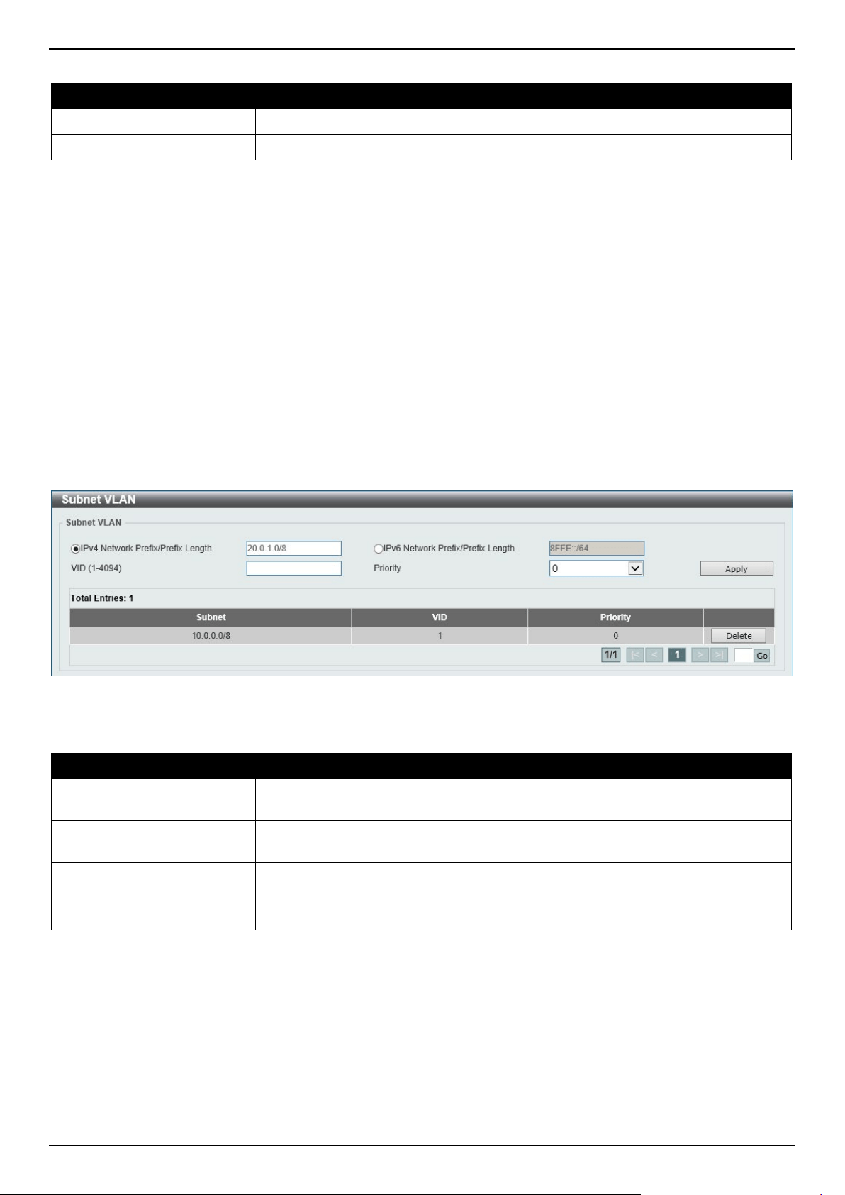
DGS-1520 Series Gigabit Ethernet Smart Managed Switch Web UI Reference Guide
141
The fields that can be configured are described below:
Parameter Description
L2VLAN Interface
Enter the ID of the Layer 2 VLAN interface here.
Description
Enter the description for the Layer 2 VLAN interface here.
Click the Apply button to accept the changes made.
Click the Find button to generate the display based on the information entered.
Click the Show All button to display all the available entries.
Click the Delete Description button to remove the description from the specified Layer 2 VLAN.
Enter a page number and click the Go button to navigate to a specific page when multiple pages exist.
Subnet VLAN
This window is used to display and configure the subnet VLAN settings. A subnet VLAN entry is an IP subnet-based
VLAN classification rule. If an untagged or priority-tagged IP packet is received on a port, its source IP address will be
used to match the subnet VLAN entries. If the source IP is in the subnet of an entry, the packet will be classified to the
VLAN defined for this subnet.
To view the following window, click L2 Features > VLAN > Subnet VLAN, as shown below:
Figure 5-34 Subnet VLAN Window
The fields that can be configured are described below:
Parameter Description
IPv4 Network Prefix / Prefix
Length
Select and enter the IPv4 address and prefix length value for the subnet VLAN
here.
IPv6 Network Prefix / Prefix
Length
Select and enter the IPv6 address and prefix length value for the subnet VLAN
here.
VID
Enter the VLAN ID for the subnet VLAN here.
Priority
Select the priority value used here. This value is between 0 and 7. A higher value
takes higher priority.
Click the Apply button to accept the changes made.
Click the Delete button to remove the specific entry.
Enter a page number and click the Go button to navigate to a specific page when multiple pages exist.
Super VLAN
This window is used to display and configure the super VLAN settings. This is used to specify a VLAN as a super
VLAN. Super VLANs are used to aggregate multiple sub-VLANs (Layer 2 broadcast domains) into an IP subnet. A
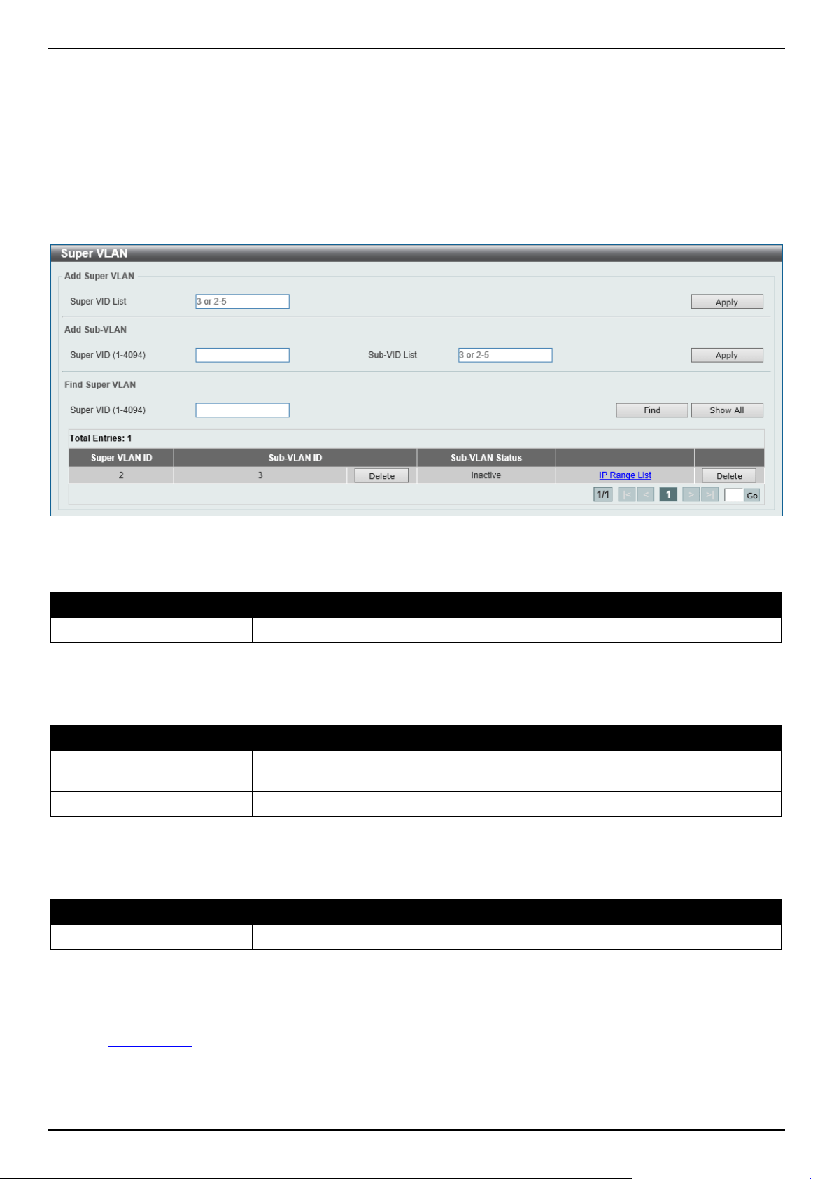
DGS-1520 Series Gigabit Ethernet Smart Managed Switch Web UI Reference Guide
142
super VLAN cannot have any physical member port. A super VLAN cannot be a sub-VLAN at the same time. Once an
IP interface is bound to a super VLAN, the proxy ARP will be enabled automatically on the interface for
communication between its sub-VLANs. Multiple super VLANs can be configured and each super VLAN can consist of
multiple sub-VLANs.
Private VLAN and super VLAN are mutually exclusive. A private VLAN cannot be configured as a super VLAN. Layer
3 routing protocols, multicast protocols, and the IPv6 protocol cannot run on a super VLAN interface.
To view the following window, click L2 Features > VLAN > Super VLAN, as shown below:
Figure 5-35 Super VLAN Window
The fields that can be configured in Add Super VLAN are described below:
Parameter Description
Super VID List
Enter the super VLAN ID(s) that will be created here.
Click the Apply button to accept the changes made.
The fields that can be configured in Add Sub VLAN are described below:
Parameter Description
Super VID
Enter the super VLAN ID that will be associated with the sub-VLAN(s) here. The
range is from 1 to 4094.
Sub-VID List
Enter the sub-VLAN ID(s) that will be associated with the super VLAN here.
Click the Apply button to accept the changes made.
The fields that can be configured in Find Super VLAN are described below:
Parameter Description
Super VID
Enter the super VLAN ID that will be displayed here. The range is from 1 to 4094.
Click the Find button to locate a specific entry based on the information entered.
Click the Show All button to display all the available entries.
Click the Delete button to remove the specific entry or to remove the sub-VLAN from the super VLAN.
Click the IP Range List link to add an IP range to the sub-VLAN.
Enter a page number and click the Go button to navigate to a specific page when multiple pages exist.
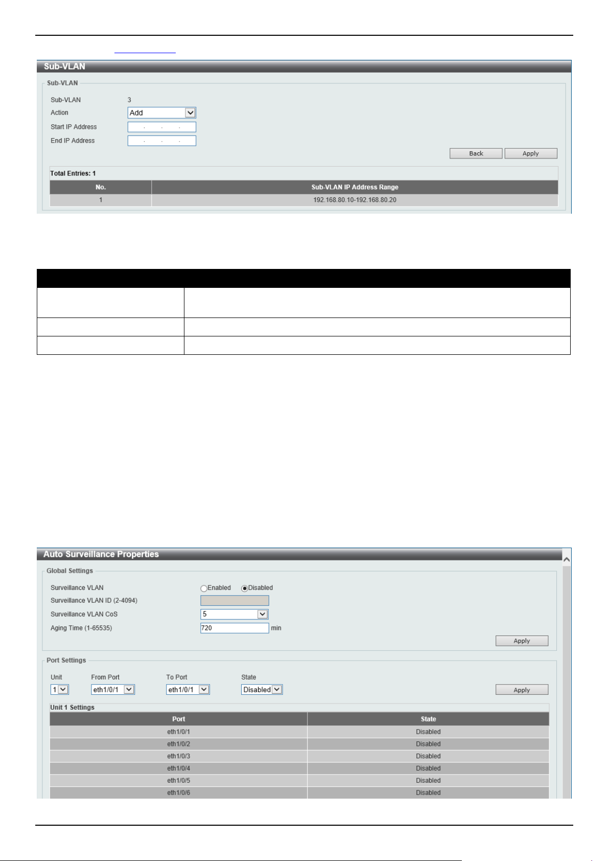
DGS-1520 Series Gigabit Ethernet Smart Managed Switch Web UI Reference Guide
143
After clicking the IP Range List link, the following page will be available.
Figure 5-36 Super VLAN (IP Range List) Window
The fields that can be configured are described below:
Parameter Description
Action Select the action that will be taken here. Options to choose from are Add and
Remove.
Start IP Address
Enter the starting IP address in the range of this sub-VLAN here.
End IP Address
Enter the ending IP address in the range of this sub-VLAN here.
Click the Back button to return to the previous page.
Click the Apply button to accept the changes made.
Auto Surveillance VLAN
Auto Surveillance Properties
This window is used to display and configure the auto surveillance VLAN properties.
To view the following window, click L2 Features > VLAN > Auto Surveillance VLAN > Auto Surveillance
Properties, as shown below:
Figure 5-37 Auto Surveillance Properties Window

DGS-1520 Series Gigabit Ethernet Smart Managed Switch Web UI Reference Guide
144
The fields that can be configured in Global Settings are described below:
Parameter Description
Surveillance VLAN
Select to enable or disable the surveillance VLAN feature here.
Surveillance VLAN ID
Enter the VLAN ID of the surveillance VLAN here. The range is from 2 to 4094. A
normal VLAN needs to be created before assigning the VLAN as a surveillance
VLAN.
Surveillance VLAN CoS
Enter the Class of Service (CoS) value for the surveillance VLAN here. The
surveillance packets arriving at the surveillance VLAN enabled port are marked
with the CoS specified here. The remarking of CoS allows the surveillance VLAN
traffic to be distinguished from data traffic in quality of service. The range is from 0
to 7.
Aging Time
Enter the aging time value here. This is used to configure the aging time for aging
out the surveillance VLAN dynamic member ports. The range is from 1 to 65535
minutes. When the last surveillance device connected to the port stops sending
traffic and the MAC address of this surveillance device is aged out, the
surveillance VLAN aging timer will be started. The port will be removed from the
surveillance VLAN after expiration of surveillance VLAN aging timer. If the
surveillance traffic resumes during the aging time, the aging timer will be
cancelled.
Click the Apply button to accept the changes made.
The fields that can be configured in Port Settings are described below:
Parameter Description
Unit
Select the Switch unit that will be used for this configuration here.
From Port - To Port
Select the range of ports that will be used for this configuration here.
State
Select to enable or disable the surveillance VLAN feature on the specified port(s)
here. When surveillance VLAN is enabled for a port, the port will automatically be
learned as an untagged surveillance VLAN member and the received untagged
surveillance packets will be forwarded to the surveillance VLAN. The received
packets are determined as surveillance packets if the source MAC addresses of
the packets comply with the Organizationally Unique Identifier (OUI) addresses.
Click the Apply button to accept the changes made.
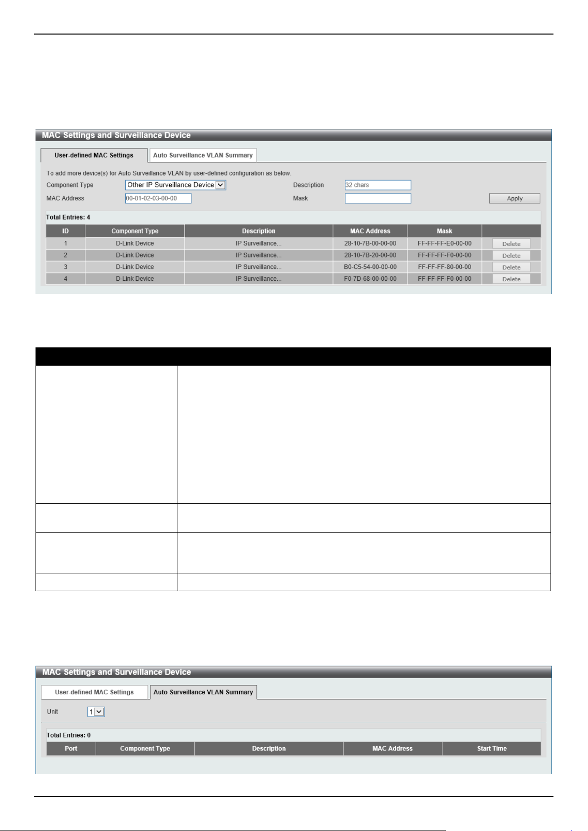
DGS-1520 Series Gigabit Ethernet Smart Managed Switch Web UI Reference Guide
145
MAC Settings and Surveillance Device
This window is used to display and configure surveillance devices and their MAC settings.
To view the following window, click L2 Features > VLAN > Auto Surveillance VLAN > MAC Settings and
Surveillance Device and select the User-defined MAC Settings tab, as shown below:
Figure 5-38 MAC Settings and Surveillance Device Window
The fields that can be configured are described below:
Parameter Description
Component Type
Select the component type here. Option to choose from are:
• Video Management server - Specifies the surveillance device type as
Video Management Server (VMS).
• VMS Client/Remote Viewer - Specifies the surveillance device type as
VMS client.
• Video Encoder - Specifies the surveillance device type as Video Encoder.
• Network Storage - Specifies the surveillance device type as Network
Storage.
• Other IP Surveillance Device - Specifies the surveillance device type as
other IP Surveillance Devices.
Description
Enter the description for the user-defined OUI here. This string can be up to 32
characters long.
MAC Address
Enter the OUI MAC address here. If the source MAC addresses of the received
packet matches any of the OUI pattern, the received packet is determined as a
surveillance packet.
Mask
Enter the matching bitmask for the OUI MAC address here.
Click the Apply button to accept the changes made.
Click the Delete button to delete the specified entry.
To view the following window, select the Auto Surveillance VLAN Summary tab, as shown below:
Figure 5-39 MAC Settings and Surveillance Device (Auto Surveillance VLAN Summary) Window
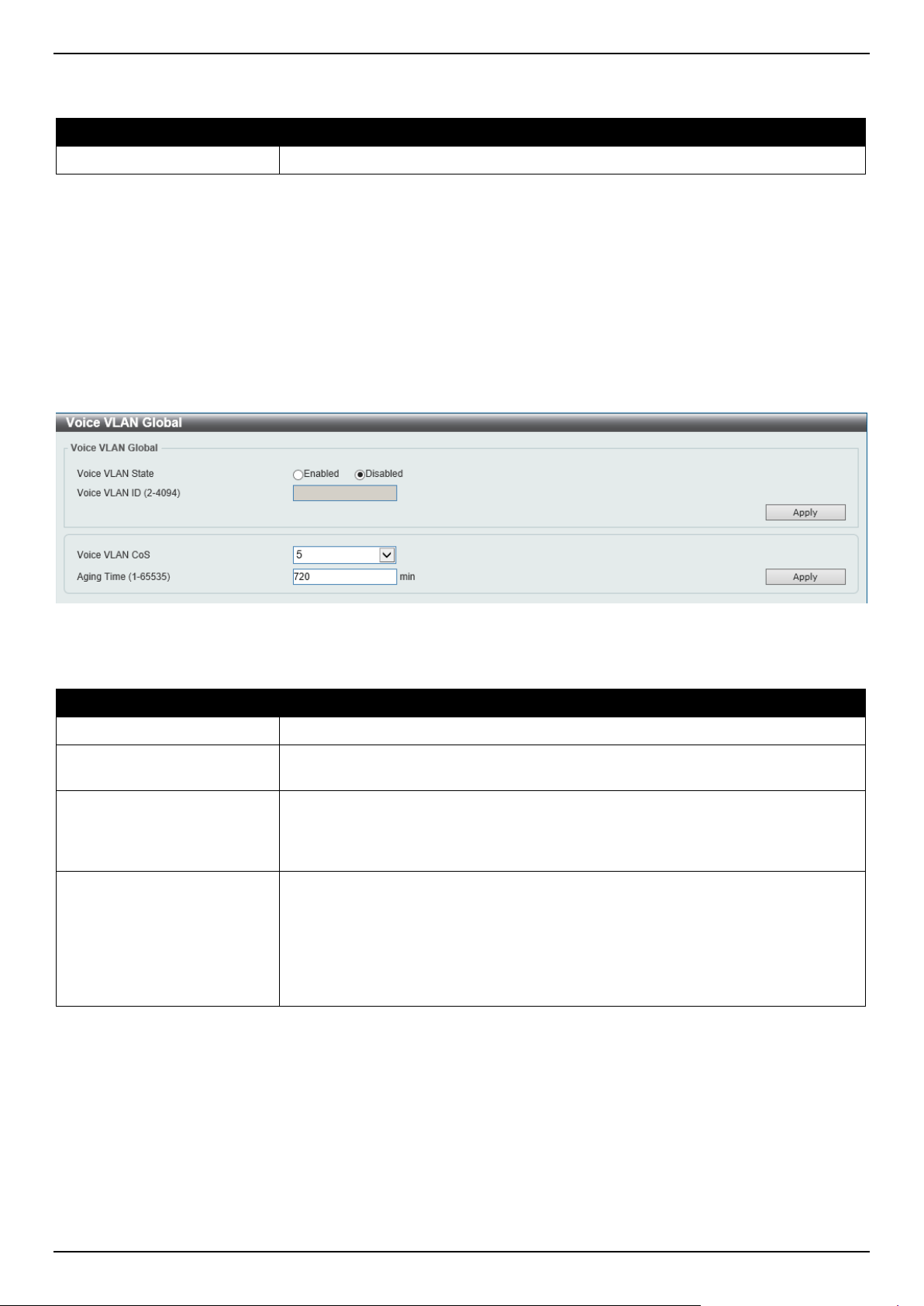
DGS-1520 Series Gigabit Ethernet Smart Managed Switch Web UI Reference Guide
146
The fields that can be configured are described below:
Parameter Description
Unit
Select the stacking unit ID of the Switch that will be used in this display here.
Voice VLAN
Voice VLAN Global
This window is used to display and configure the global voice VLAN settings. This is used to enable the global voice
VLAN function and to specify the voice VLAN on the Switch. The Switch has only one voice VLAN.
To view the following window, click L2 Features > VLAN > Voice VLAN > Voice VLAN Global, as shown below:
Figure 5-40 Voice VLAN Global Window
The fields that can be configured are described below:
Parameter Description
Voice VLAN State
Select to globally enable or disable the voice VLAN feature here.
Voice VLAN ID
Enter the VLAN ID of the voice VLAN here. The VLAN to be specified as the voice
VLAN needs to pre-exist before configuration. The range is from 2 to 4094.
Voice VLAN CoS
Select the CoS of the voice VLAN here. The range is from 0 to 7. The voice
packets arriving at the voice VLAN enabled port are marked as the CoS specified
here. The remarking of CoS packets allow the voice VLAN traffic to be
distinguished from data traffic in Quality of Service.
Aging Time
Enter the aging time value here. This is used to configure the aging time for aging
out the automatically learned voice device and voice VLAN information. When the
last voice device connected to the port stops sending traffic and the MAC address
of this voice device is aged out from FDB, the voice VLAN aging timer will be
started. The port will be removed from the voice VLAN after the expiration of the
voice VLAN aging timer. If voice traffic resumes during the aging time, the aging
timer will be cancelled. The range is from 1 to 65535 minutes.
Click the Apply button to accept the changes made.
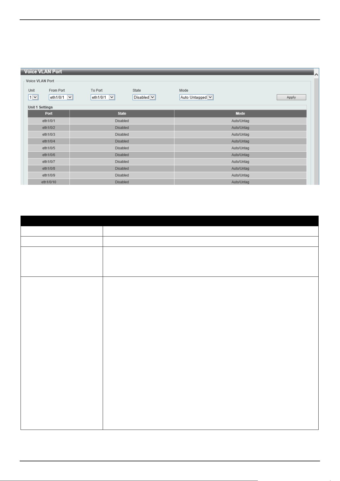
DGS-1520 Series Gigabit Ethernet Smart Managed Switch Web UI Reference Guide
147
Voice VLAN Port
This window is used to display and configure the voice VLAN interface settings.
To view the following window, click L2 Features > VLAN > Voice VLAN > Voice VLAN Port, as shown below:
Figure 5-41 Voice VLAN Port Window
The fields that can be configured are described below:
Parameter Description
Unit
Select the Switch unit that will be used for this configuration here.
From Port - To Port
Select the range of ports that will be used for this configuration here.
State
Select to enable or disable the voice VLAN feature on the specified port(s) here.
When the voice VLAN is enabled for a port, the received voice packets will be
forwarded in the voice VLAN. The received packets are determined as voice
packets if the source MAC addresses of packets comply with the OUI addresses.
Mode
Select the mode here. Options to choose from are:
• Auto Untagged - Specifies that voice VLAN untagged membership will be
automatically learned.
• Auto Tagged - Specifies that voice VLAN tagged membership will be
automatically learned.
• Manual - Specifies that voice VLAN membership will be manually
configured.
If auto-learning is enabled, the port will automatically be learned as a voice VLAN
member. This membership will automatically be aged out. When the port is
working in the auto-tagged mode and the port captures a voice device through the
device's OUI, it will join the voice VLAN as a tagged member automatically. When
the voice device sends tagged packets, the Switch will change its priority. When
the voice device sends untagged packets, it will forward them in the Port VLAN ID
(PVID).
When the port is working in auto-untagged mode, and the port captures a voice
device through the device's OUI, it will join the voice VLAN as an untagged
member automatically. When the voice device sends tagged packets, the Switch
will change its priority. When the voice device sends untagged packets, it will
forward them in the voice VLAN.
When the Switch receives LLDP-MED packets, it checks the VLAN ID, tagged flag,
and priority flag. The Switch should follow the tagged flag and priority setting.
Click the Apply button to accept the changes made.
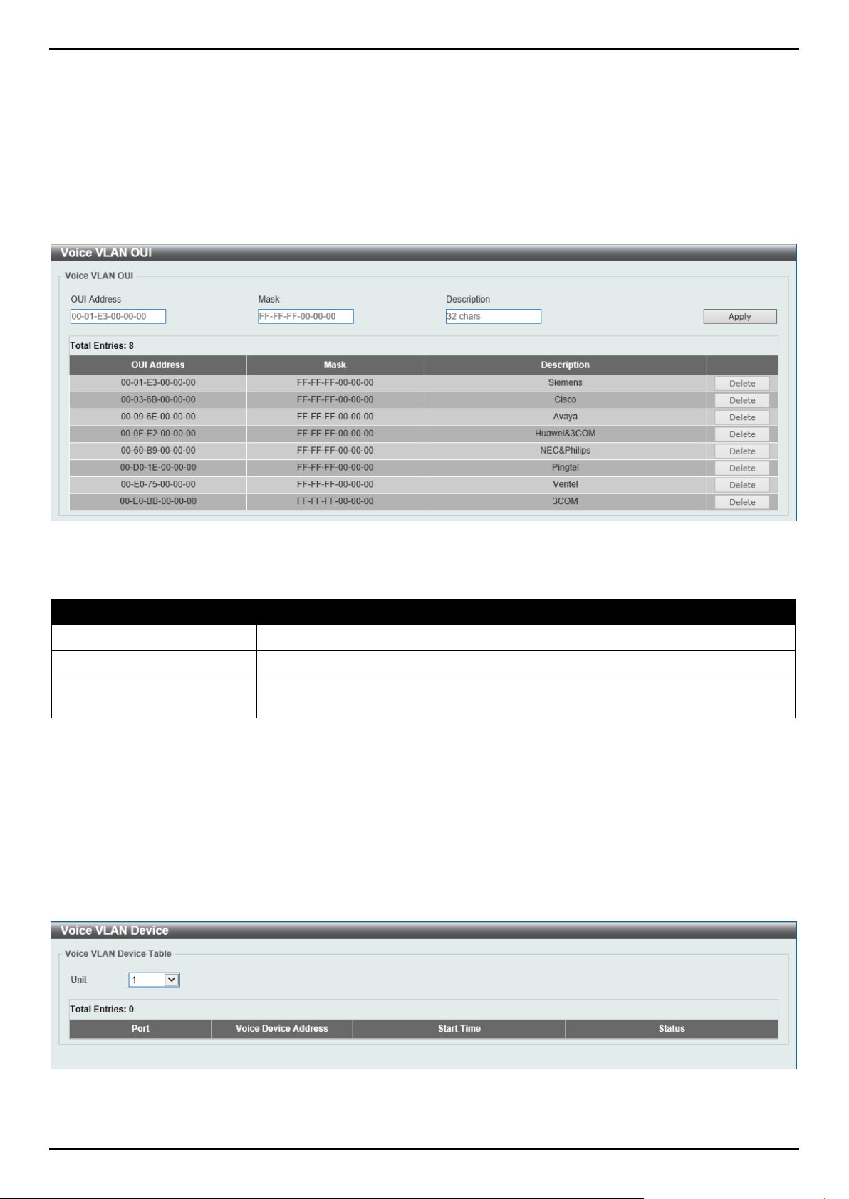
DGS-1520 Series Gigabit Ethernet Smart Managed Switch Web UI Reference Guide
148
Voice VLAN OUI
This window is used to display and configure the voice VLAN OUI settings. Use this window to add a user-defined OUI
for the voice VLAN. The OUI for the voice VLAN is used to identify the voice traffic by using the voice VLAN function.
If the source MAC address of the received packet matches any of the OUI patterns, the received packet is determined
as a voice packet.
The user-defined OUI cannot be the same as the default OUI. The default OUI cannot be deleted.
To view the following window, click L2 Features > VLAN > Voice VLAN > Voice VLAN OUI, as shown below:
Figure 5-42 Voice VLAN OUI Window
The fields that can be configured are described below:
Parameter Description
OUI Address
Enter the voice VLAN OUI MAC address here.
Mask
Enter the matching bitmask for the voice VLAN OUI MAC address here.
Description
Enter the description for the user-defined OUI MAC address here. This string can
be up to 32 characters long.
Click the Apply button to accept the changes made.
Click the Delete button to delete the specified entry.
Voice VLAN Device
This window is used to view the voice VLAN device table.
To view the following window, click L2 Features > VLAN > Voice VLAN > Voice VLAN Device, as shown below:
Figure 5-43 Voice VLAN Device Window
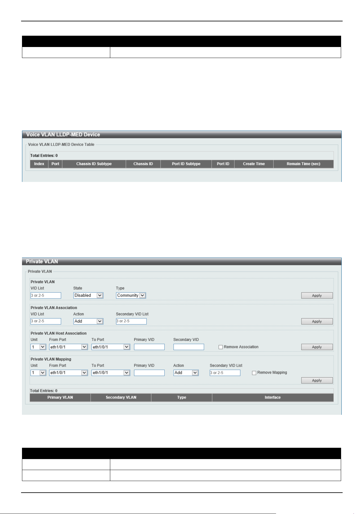
DGS-1520 Series Gigabit Ethernet Smart Managed Switch Web UI Reference Guide
149
The fields that can be configured are described below:
Parameter Description
Unit
Select the Switch unit that will be used in this display here.
Voice VLAN LLDP-MED Device
This window is used to view the voice VLAN LLDP-MED device table.
To view the following window, click L2 Features > VLAN > Voice VLAN > Voice VLAN LLDP-MED Device, as
shown below:
Figure 5-44 Voice VLAN LLDP-MED Device Window
Private VLAN
This window is used to display and configure the private VLAN settings.
To view the following window, click L2 Features > VLAN > Private VLAN, as shown below:
Figure 5-45 Private VLAN Window
The fields that can be configured for Private VLAN are described below:
Parameter Description
VID List
Enter the private VLAN ID list here.
State
Select to enable or disable the private VLAN state here.

DGS-1520 Series Gigabit Ethernet Smart Managed Switch Web UI Reference Guide
150
Parameter Description
Type
Select the type of private VLAN that will be created here. Options to choose from
are Community, Isolated, and Primary.
Click the Apply button to accept the changes made.
The fields that can be configured for Private VLAN Association are described below:
Parameter Description
VID List
Enter the private VLAN ID list here.
Action
Select the action that will be taken for the private VLAN here. Options to choose
from are Add, Remove, and Disabled.
Secondary VID List
Enter the secondary private VLAN ID here.
Click the Apply button to accept the changes made.
The fields that can be configured for Private VLAN Host Association are described below:
Parameter Description
Unit
Select the Switch unit that will be used for this configuration here.
From Port - To Port
Select the range of ports that will be used for this configuration here.
Primary VID
Enter the primary private VLAN ID here.
Secondary VID Enter the secondary private VLAN ID here. When ticking the Remove
Association option, specifies that this configuration will not be enabled.
Click the Apply button to accept the changes made.
The fields that can be configured for Private VLAN Mapping are described below:
Parameter Description
Unit
Select the Switch unit that will be used for this configuration here.
From Port - To Port
Select the range of ports that will be used for this configuration here.
Primary VID
Enter the primary private VLAN ID here.
Action Select Add to add a new entry based in the information entered.
Select Remove to remove an entry based in the information entered.
Secondary VID List Enter the secondary private VLAN ID here. When ticking the Remove Mapping
option, this specifies that this configuration will not be enabled.
Click the Apply button to accept the changes made.
VLAN Tunnel
Dot1q Tunnel
This window is used to display and configure the 802.1Q VLAN tunnel settings.
An 802.1Q tunnel port behaves as a User Network Interface (UNI) port of a service VLAN. The trunk ports, which are
tagged members of the service VLAN, behave as the Network Node Interface (NNI) ports of the service VLAN.
Only configure the 802.1Q tunneling Ethernet type on ports that are connected to the provider bridge network, which
receives and transmits the service VLAN tagged frames. If the tunnel Ethernet type is configured, the specified value
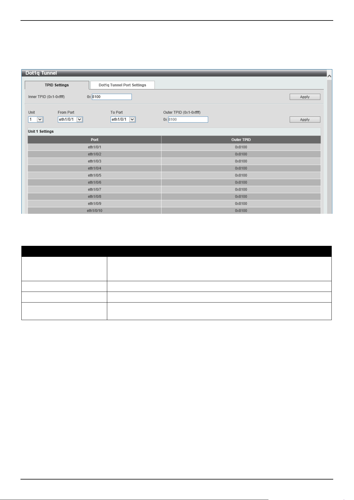
DGS-1520 Series Gigabit Ethernet Smart Managed Switch Web UI Reference Guide
151
will be the Tag Protocol ID (TPID) in the outer VLAN tag of the transmitted frames of the port. The specified TPID is
also used to identify the service VLAN tag for the received frame on this port.
To view the following window, click L2 Features > VLAN Tunnel > Dot1q Tunnel and select the TPID Settings tab,
as shown below:
Figure 5-46 Dot1q Tunnel Window
The fields that can be configured are described below:
Parameter Description
Inner TPID
Enter the inner TPID value here. This value is in the hexadecimal form. The range
is from 0x1 to 0xFFFF. The inner TPID is used to decide if the ingress packet is C-
tagged. The inner TPID can be configured per system.
Unit
Select the Switch unit ID that will be used here.
From Port - To Port
Select the port range that will be used here.
Outer TPID
Enter the outer TPID value here. This value is in the hexadecimal form. The range
is from 0x1 to 0xFFFF.
Click the Apply button to accept the changes made.
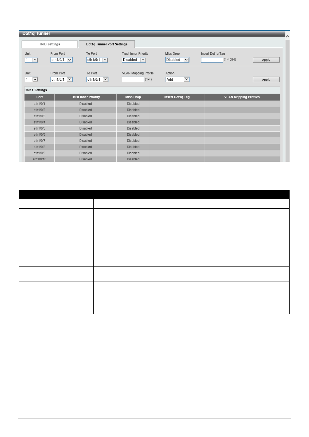
DGS-1520 Series Gigabit Ethernet Smart Managed Switch Web UI Reference Guide
152
To view the following window, select the Dot1q Tunnel Port Settings tab, as shown below:
Figure 5-47 Dot1q Tunnel Settings (Dot1q Tunnel Port Settings) Window
The fields that can be configured are described below:
Parameter Description
Unit
Select the Switch unit ID that will be used here.
From Port - To Port
Select the port range that will be used here.
Trust Inner Priority
Select to enable or disable the 802.1Q Inner Trust Priority feature here. When the
trusting priority option is enabled on an 802.1Q tunnel port, the priority of the VLAN
tag in the received packets will be copied to the service VLAN tag.
Miss Drop
Select to enable or disable the Miss Drop feature here. If the VLAN mapping Miss
Drop option is enabled on the receiving port, when the original VLAN of the
received packets cannot match the VLAN mapping entries or rules on this port, the
received packets will be dropped.
Insert Dot1q Tag
Enter the 802.1Q VLAN ID that is inserted to the untagged packets, which are
received, on the 802.1Q tunnel port(s) here. The range is from 1 to 4094.
VLAN Mapping Profile
Enter the ID of the VLAN mapping profile here. A lower ID has a higher priority.
The ID range is from 1 to 4.
Action Select Add to add a new entry based in the information entered.
Select Remove to remove an entry based in the information entered.
Click the Apply button to accept the changes made.
VLAN Mapping
This window is used to display and configure the VLAN mapping settings. If a profile is applied on an interface, the
Switch matches the incoming packets according to the rules of the profile. If the packet matches a rule, the action of
the rule will be taken. This action may be adding or replacing the outer-VID, specifying the priority of the new outer-
TAG or specifying the packet's new inner-VID.
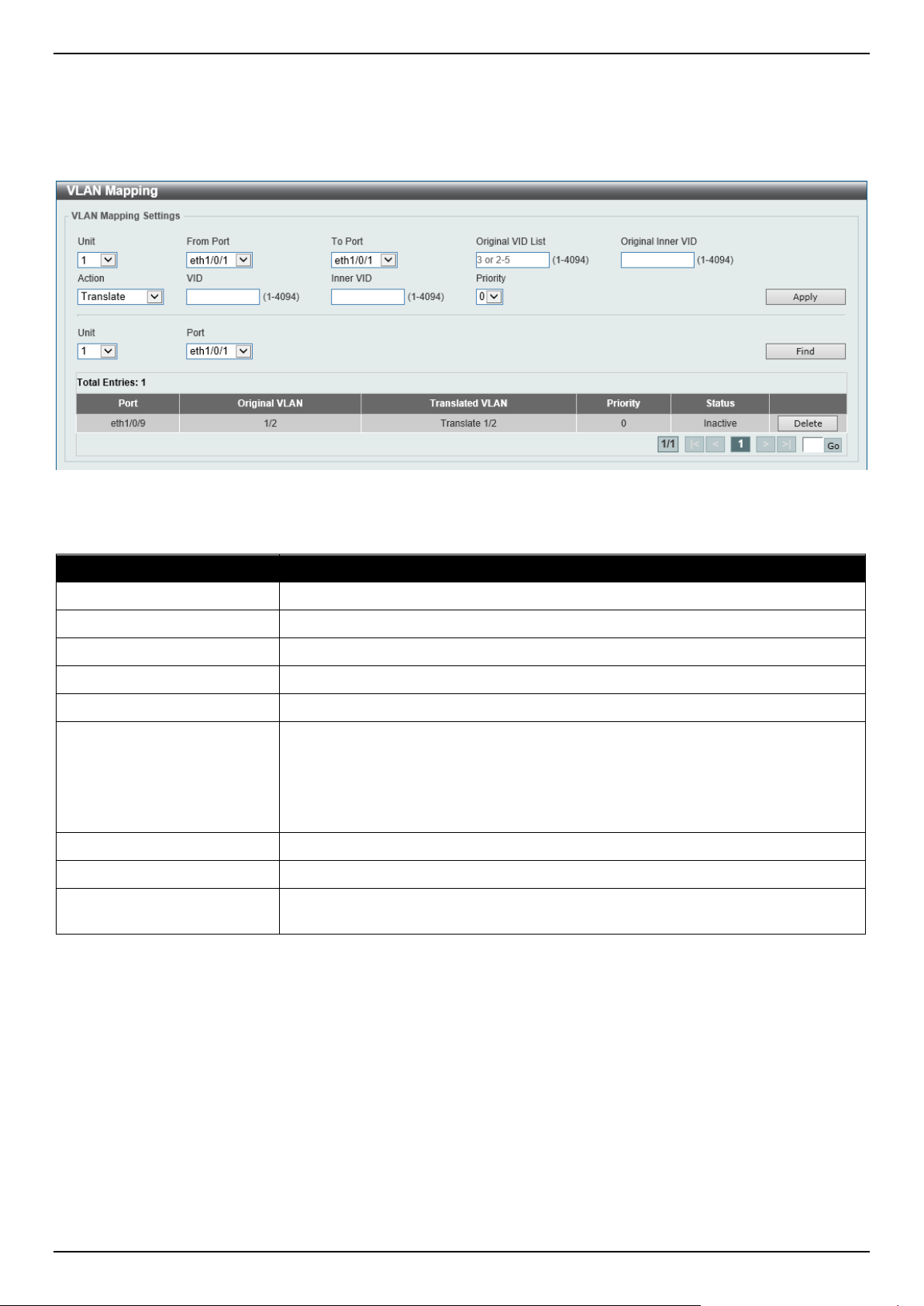
DGS-1520 Series Gigabit Ethernet Smart Managed Switch Web UI Reference Guide
153
The match order depends on the sequence number of the rule in the profile and stops when matched first. If the
sequence number is not specified, it will be allocated automatically. The sequence number begins from 10 and
increments 10. Multiple different types of profiles can be configured on one interface.
To view the following window, click L2 Features > VLAN Tunnel > VLAN Mapping, as shown below:
Figure 5-48 VLAN Mapping Settings Window
The fields that can be configured are described below:
Parameter Description
Unit
Select the Switch unit ID that will be used here.
From Port - To Port
Select the port range that will be used here.
Port
Select the port that will be used for the search here.
Original VID List
Enter the original VLAN ID list here. The range is from 1 to 4094.
Original Inner VID
Enter the original inner VLAN ID here. The range is from 1 to 4094.
Action
Select the action that will be taken here. Options to choose from are:
• Translate - Specifies that the outer-VID will replace the outer-VID of the
matched packets.
• Dot1q-tunnel - Specifies that the outer-VID will be added for matched
packets.
VID
Enter the VLAN ID here. The range is from 1 to 4094.
Inner VID
Enter the inner VLAN ID here. The range is from 1 to 4094.
Priority
Select the 802.1p priority value here. The range is from 0 to 7. A higher value has
a higher priority.
Click the Apply button to accept the changes made.
Click the Find button to locate a specific entry based on the information entered.
Click the Delete button to delete the specified entry.
Enter a page number and click the Go button to navigate to a specific page when multiple pages exist.
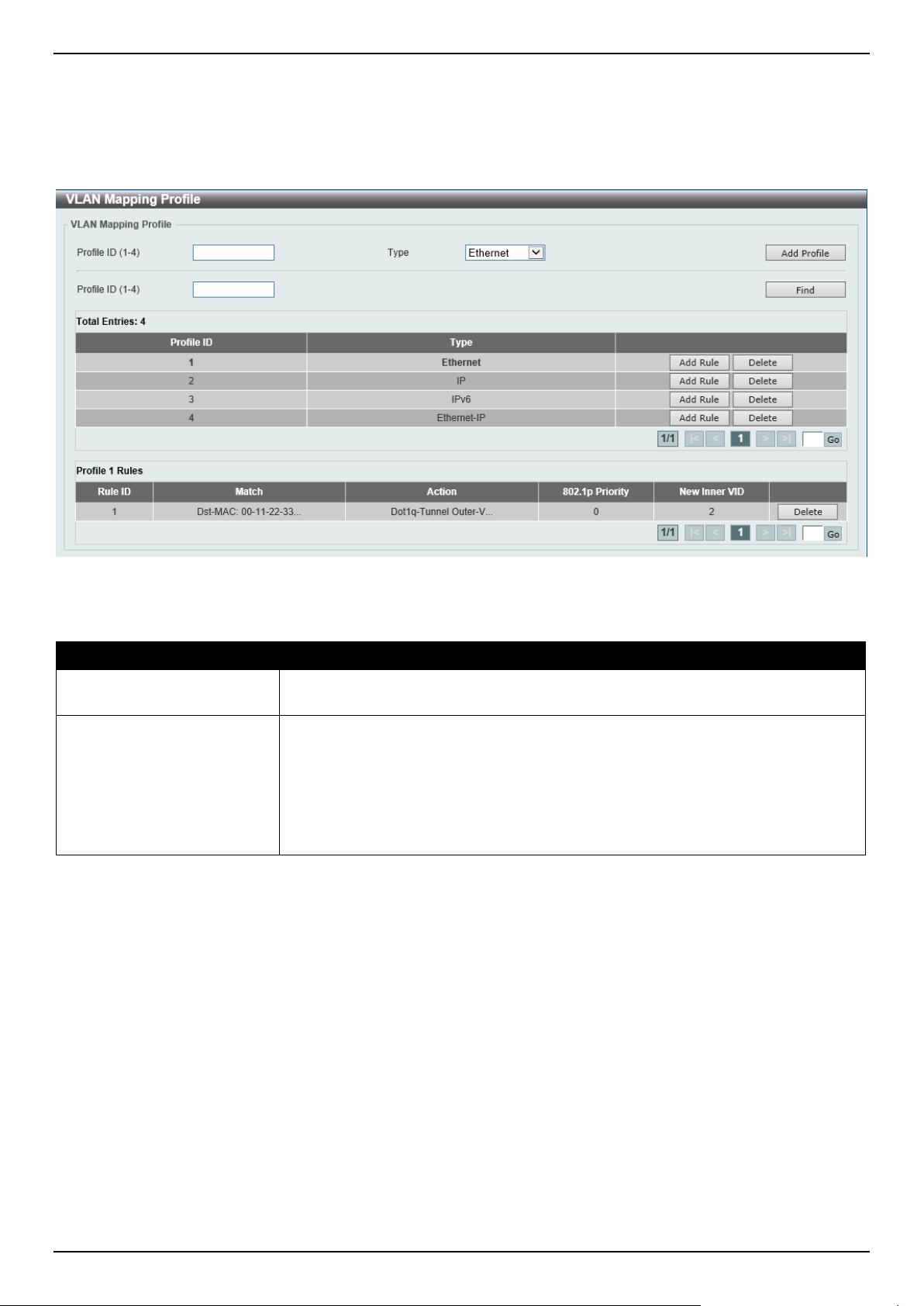
DGS-1520 Series Gigabit Ethernet Smart Managed Switch Web UI Reference Guide
154
VLAN Mapping Profile
This window is used to display and configure the VLAN mapping profile settings.
To view the following window, click L2 Features > VLAN Tunnel > VLAN Mapping Profile, as shown below:
Figure 5-49 VLAN Mapping Profile Window
The fields that can be configured are described below:
Parameter Description
Profile ID
Enter the ID of the VLAN mapping profile here. A lower ID has a higher priority.
The ID range is from 1 to 4.
Type
Select the profile type here. Different profiles can match different fields. Options to
choose from are:
• Ethernet - The profile can match Layer 2 fields.
• IP - The profile can match Layer 3 IP fields.
• IPv6 - The profile can match IPv6 destination or source addresses.
• Ethernet-IP - The profile can match Layer 2 and Layer 3 IP fields.
Click the Add Profile button to add a new VLAN mapping profile.
Click the Find button to locate a specific entry based on the information entered.
Click the Add Rule button to create a new rule.
Click the Delete button to remove the specified entry.
Enter a page number and click the Go button to navigate to a specific page when multiple pages exist.
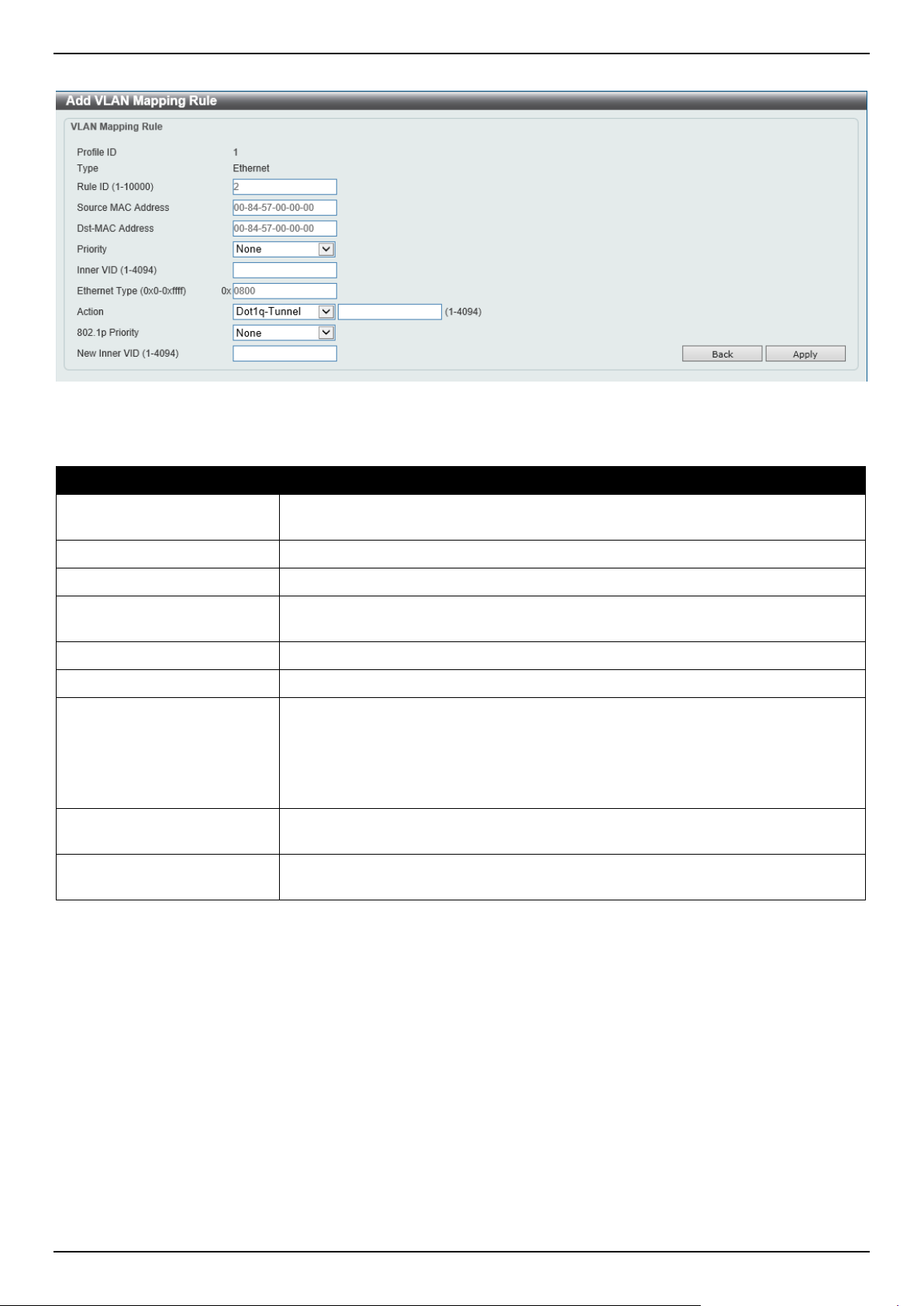
DGS-1520 Series Gigabit Ethernet Smart Managed Switch Web UI Reference Guide
155
After clicking the Add Rule button next to an Ethernet type profile, the following page will appear.
Figure 5-50 VLAN Mapping Profile (Ethernet, Add Rule) Window
The fields that can be configured are described below:
Parameter Description
Rule ID
Enter the VLAN mapping rule ID here. If not specified, the rule ID begins from 10
and is incremented by 10 for every new rule. The range is from 1 to 10000.
Source MAC Address
Enter the source MAC address here.
Destination MAC Address
Enter the destination MAC address here.
Priority
Select the 802.1p priority value here. The range is from 0 to 7. A higher value has
a higher priority.
Inner VID
Enter the inner VLAN ID here. The range is from 1 to 4094.
Ethernet Type
Enter the Ethernet type value here. The range is from 0x0 to 0xFFFF.
Action
Select the action that will be taken here. Options to choose from are:
• Dot1q-Tunnel - Specifies that the outer-VID will be added for matched
packets.
• Translate - Specifies that the outer-VID will replace the outer-VID of the
matched packets.
802.1p Priority
Select the 802.1p priority value here. The range is from 0 to 7. A higher value has
a higher priority.
New Inner VID After selecting Dot1q-Tunnel as the action, enter the new inner VLAN ID here.
The range is from 1 to 4094.
Click the Back button to return to the previous window.
Click the Apply button to accept the changes made.
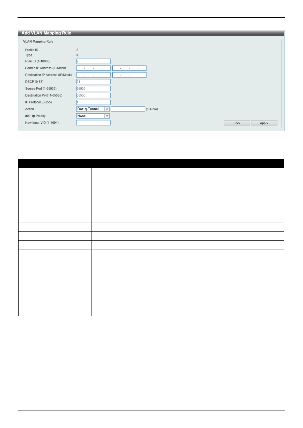
DGS-1520 Series Gigabit Ethernet Smart Managed Switch Web UI Reference Guide
156
After clicking the Add Rule button next to an IP type profile, the following page will appear.
Figure 5-51 VLAN Mapping Profile (IP, Add Rule) Window
The fields that can be configured are described below:
Parameter Description
Rule ID
Enter the VLAN mapping rule ID here. If not specified, the rule ID begins from 10
and is incremented by 10 for every new rule. The range is from 1 to 10000
Source IP Address
(IP/Mask)
Enter the source IPv4 address and subnet mask here.
Destination IP Address
(IP/Mask)
Enter the destination IPv4 address and subnet mask here.
DSCP
Enter the DSCP value here. The range is from 0 to 63.
Source Port
Enter the source TCP/UDP port number here. The range is from 1 to 65535.
Destination Port
Enter the destination TCP/UDP port number here. The range is from 1 to 65535.
IP Protocol
Enter the Layer 3 IP protocol value here. The range is from 0 to 255.
Action
Select the action that will be taken here. Options to choose from are:
• Dot1q-Tunnel - Specifies that the outer-VID will be added for matched
packets.
• Translate - Specifies that the outer-VID will replace the outer-VID of the
matched packets.
802.1p Priority
Select the 802.1p priority value here. The range is from 0 to 7. A higher value has
a higher priority.
New Inner VID After selecting Dot1q-Tunnel as the action, enter the new inner VLAN ID here.
The range is from 1 to 4094.
Click the Back button to return to the previous window.
Click the Apply button to accept the changes made.
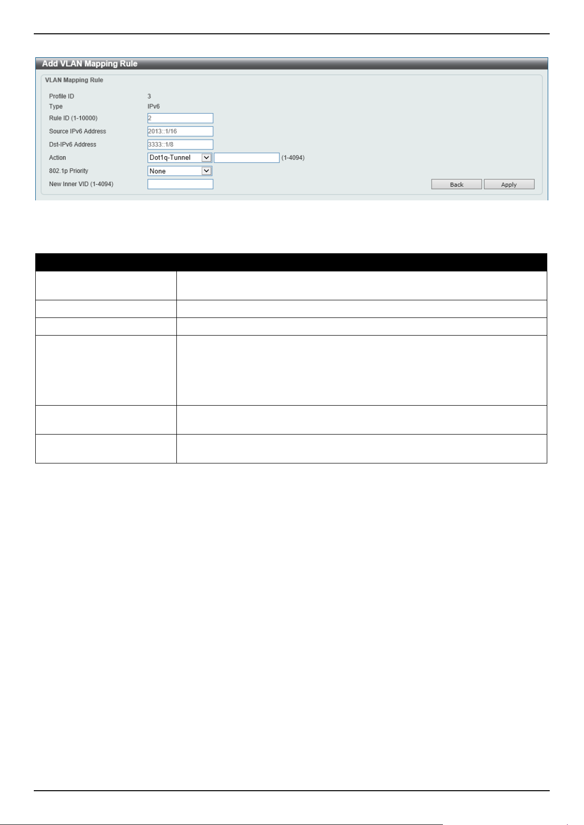
DGS-1520 Series Gigabit Ethernet Smart Managed Switch Web UI Reference Guide
157
After clicking the Add Rule button next to an IPv6 type profile, the following page will appear.
Figure 5-52 VLAN Mapping Profile (IPv6, Add Rule) Window
The fields that can be configured are described below:
Parameter Description
Rule ID
Enter the VLAN mapping rule ID here. If not specified, the rule ID begins from 10
and is incremented by 10 for every new rule. The range is from 1 to 10000
Source IPv6 Address
Enter the source IPv6 address and prefix length here.
Destination IPv6 Address
Enter the destination IPv6 address and prefix length here.
Action
Select the action that will be taken here. Options to choose from are:
• Dot1q-Tunnel - Specifies that the outer-VID will be added for matched
packets.
• Translate - Specifies that the outer-VID will replace the outer-VID of the
matched packets.
802.1p Priority
Select the 802.1p priority value here. The range is from 0 to 7. A higher value has
a higher priority.
New Inner VID After selecting Dot1q-Tunnel as the action, enter the new inner VLAN ID here.
The range is from 1 to 4094.
Click the Back button to return to the previous window.
Click the Apply button to accept the changes made.
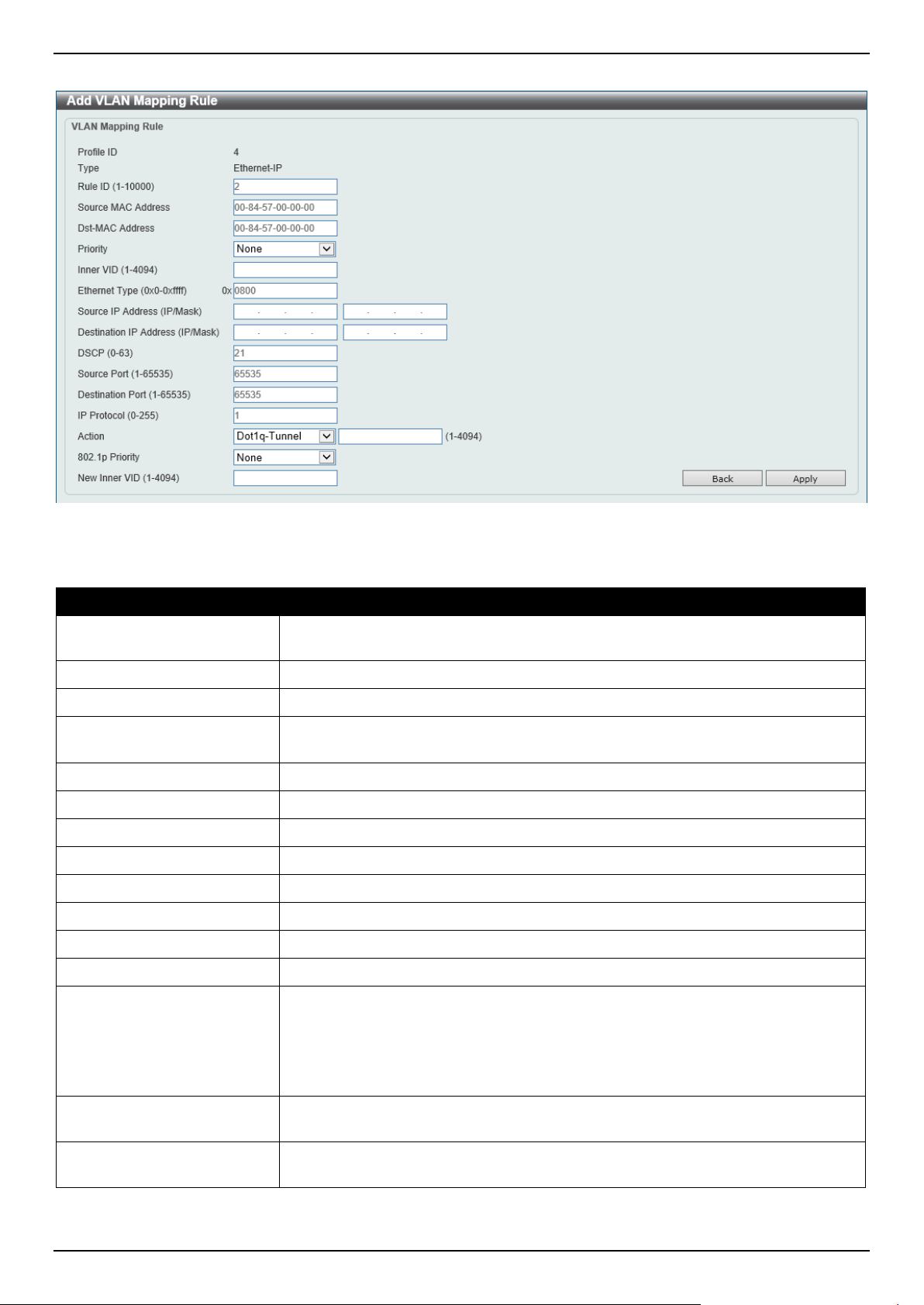
DGS-1520 Series Gigabit Ethernet Smart Managed Switch Web UI Reference Guide
158
After clicking the Add Rule button next to an Ethernet-IP type profile, the following page will appear.
Figure 5-53 VLAN Mapping Profile (Ethernet-IP, Add Rule) Window
The fields that can be configured are described below:
Parameter Description
Rule ID
Enter the VLAN mapping rule ID here. If not specified, the rule ID begins from 10
and is incremented by 10 for every new rule. The range is from 1 to 10000
Source MAC Address
Enter the source MAC address here.
Destination MAC Address
Enter the destination MAC address here.
Priority
Select the 802.1p priority value here. The range is from 0 to 7. A higher value has
a higher priority.
Inner VID
Enter the inner VLAN ID here. The range is from 1 to 4094.
Ethernet Type
Enter the Ethernet type value here. The range is from 0x0 to 0xFFFF.
Source IP Address
Enter the source IPv4 address and subnet mask here.
Destination IP Address
Enter the destination IPv4 address and subnet mask here.
DSCP
Enter the DSCP value here. The range is from 0 to 63.
Source Port
Enter the source TCP/UDP port number here. The range is from 1 to 65535.
Destination Port
Enter the destination TCP/UDP port number here. The range is from 1 to 65535.
IP Protocol
Enter the Layer 3 IP protocol value here. The range is from 0 to 255.
Action
Select the action that will be taken here. Options to choose from are:
• Dot1q-Tunnel - Specifies that the outer-VID will be added for matched
packets.
• Translate - Specifies that the outer-VID will replace the outer-VID of the
matched packets.
802.1p Priority
Select the IEEE 802.1p priority value here. The range is from 0 to 7. A higher value
has a higher priority.
New Inner VID After selecting Dot1q-Tunnel as the action, enter the new inner VLAN ID here.
The range is from 1 to 4094.
Click the Back button to return to the previous window.

DGS-1520 Series Gigabit Ethernet Smart Managed Switch Web UI Reference Guide
159
Click the Apply button to accept the changes made.
STP
This Switch supports three versions of the Spanning Tree Protocol (STP): IEEE 802.1D-1998 STP, IEEE 802.1D-2004
Rapid STP, and IEEE 802.1Q-2005 MSTP. The IEEE 802.1D-1998 STP standard will be familiar to most networking
professionals. However, as IEEE 802.1D-2004 RSTP and IEEE 802.1Q-2005 MSTP have been recently introduced to
D-Link managed Ethernet Switches, a brief introduction to the technology is provided below followed by a description
of how to set up IEEE 802.1D-1998 STP, IEEE 802.1D-2004 RSTP, and IEEE 802.1Q-2005 MSTP.
802.1Q-2005 MSTP
The Multiple Spanning Tree Protocol (MSTP) is a standard defined by the IEEE community that allows multiple VLANs
to be mapped to a single spanning tree instance, which will provide multiple pathways across the network. Therefore,
these MSTP configurations will balance the traffic load, preventing wide scale disruptions when a single spanning tree
instance fails. This will allow for faster convergences of new topologies for the failed instance.
Frames designated for these VLANs will be processed quickly and completely throughout interconnected bridges
utilizing any of the three spanning tree protocols (STP, RSTP, or MSTP).
A Multiple Spanning Tree Instance (MSTI) ID will classify these instances. MSTP will connect multiple spanning trees
with a Common and Internal Spanning Tree (CIST). The CIST will automatically determine each MSTP region, its
maximum possible extent and will appear as one virtual bridge that runs a single spanning tree instance. Frames
assigned to different VLANs will follow different data routes within administratively established regions on the network,
continuing to allow simple and full processing of frames, regardless of administrative errors in defining VLANs and
their respective spanning trees.
Each Switch utilizing the MSTP on a network will share a single MSTP configuration that will have the following three
attributes:
• A configuration name defined by an alphanumeric string of up to 32 characters (defined in the MST
Configuration Identification window in the Configuration Name field).
• A configuration revision number (named here as a Revision Level and found in the MST Configuration
Identification window)
• A 4094-element table (defined here as a VID List in the MST Configuration Identification window), which will
associate each of the possible 4094 VLANs supported by the Switch for a given instance.
To utilize the MSTP function on the Switch, three steps need to be taken:
• The Switch must be set to the MSTP setting (found in the STP Global Settings window in the STP Mode field).
• The correct spanning tree priority for the MSTP instance must be entered (defined here as a Priority in the
MSTP Port Information window when configuring MSTI ID settings).
• VLANs that will be shared must be added to the MSTP Instance ID (defined here as a VID List in the MST
Configuration Identification window when configuring an MSTI ID settings).
802.1D-2004 Rapid Spanning Tree
The Switch implements three versions of the Spanning Tree Protocol, the Multiple Spanning Tree Protocol (MSTP) as
defined by IEEE 802.1Q-2005, the Rapid Spanning Tree Protocol (RSTP) as defined by IEEE 802.1D-2004 and a
version compatible with IEEE 802.1D-1998. RSTP can operate with legacy equipment implementing IEEE 802.1D-
1998; however, the advantages of using RSTP will be lost. This section introduces some new Spanning Tree concepts
and illustrates the main differences between the two protocols.
Port Transition States
An essential difference between the three protocols is in the way ports transition to a forwarding state and in the way,
this transition relates to the role of the port (forwarding or not forwarding) in the topology. MSTP and RSTP combine

DGS-1520 Series Gigabit Ethernet Smart Managed Switch Web UI Reference Guide
160
the transition states Disabled, Blocking, and Listening used in 802.1D-1998 and create a single state called
Discarding. In either case, ports do not forward packets. In the STP port transition states Disabled, Blocking, or
Listening or in the RSTP/MSTP port state Discarding, there is no functional difference, the port is not active in the
network topology. The table below compares how the three protocols differ regarding the port state transition.
All three protocols calculate a stable topology in the same way. Every segment will have a single path to the root
bridge. All bridges listen for BPDU packets. However, BPDU packets are sent more frequently, with every Hello
packet. BPDU packets are sent even if a BPDU packet was not received. Therefore, each link between bridges is
sensitive to the status of the link. Ultimately, this difference results in faster detection of failed links, and therefore
faster topology adjustment. A drawback of IEEE 802.1D-1998 is this absence of immediate feedback from adjacent
bridges.
802.1Q-2005 MSTP 802.1D-2004 RSTP 802.1D-1998 STP Forwarding Learning
Disabled Disabled Disabled No No
Discarding Discarding Blocking
No No
Discarding Discarding Listening
No No
Learning Learning Learning
No
Yes
Forwarding Forwarding Forwarding Yes Yes
RSTP is capable of a more rapid transition to the Forwarding state. RSTP no longer relies on timer configurations and
RSTP-compliant bridges are sensitive to feedback from other RSTP-compliant bridge links. Ports do not need to wait
for the topology to stabilize before transitioning to a Forwarding state. In order to allow this rapid transition, the
protocol introduces two new variables: the Edge Port and the Point-to-Point (P2P) port.
Edge Port
A port can be configured as an Edge Port if it is directly connected to a segment where a loop cannot be created. An
example would be a port connected directly to a single workstation. Ports that are designated as edge ports transition
to a forwarding state immediately without going through the Listening and Learning states. An Edge Port loses its
status if it receives a BPDU packet, after which it immediately becomes a normal spanning tree port.
P2P Port
A P2P port is also capable of rapid transition. P2P ports may be used to connect to other bridges. Under RSTP/MSTP,
all ports operating in full-duplex mode are considered to be P2P ports unless manually overridden through
configuration.
802.1D-1998/802.1D-2004/802.1Q-2005 Compatibility
MSTP or RSTP can interoperate with legacy equipment and are capable of automatically adjusting BPDU packets to
802.1D-1998 format when necessary. However, any segment using 802.1D-1998 STP will not benefit from the rapid
transition and rapid topology change detection of MSTP or RSTP. The protocol also includes a variable used for
migration in the event that legacy equipment on a segment is updated to use RSTP or MSTP.
The Spanning Tree Protocol (STP) operates on two levels:
• On the Switch level, the settings are globally implemented.
• On the port level, the settings are implemented on a user-defined group of ports.
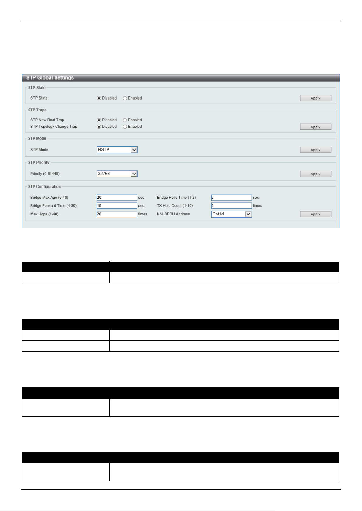
DGS-1520 Series Gigabit Ethernet Smart Managed Switch Web UI Reference Guide
161
STP Global Settings
This window is used to display and configure the global STP settings.
To view the following window, click L2 Features > STP > STP Global Settings, as shown below:
Figure 5-54 STP Global Settings Window
The field that can be configured for STP State is described below:
Parameter Description
STP State
Select to enable or disable the global STP state here.
Click the Apply button to accept the changes made.
The fields that can be configured for STP Traps are described below:
Parameter Description
STP New Root Trap
Select to enable or disable the STP New Root Trap option here.
STP Topology Change Trap
Select to enable or disable the STP Topology Change Trap option here.
Click the Apply button to accept the changes made.
The fields that can be configured for STP Mode are described below:
Parameter Description
STP Mode Select the STP mode used here. Options to choose from are MSTP, RSTP, and
STP.
Click the Apply button to accept the changes made.
The fields that can be configured for STP Priority are described below:
Parameter Description
Priority
Select the STP priority value here. This value is between 0 and 61440. By default,
this value is 32768. The lower the value, the higher the priority.

DGS-1520 Series Gigabit Ethernet Smart Managed Switch Web UI Reference Guide
162
Click the Apply button to accept the changes made.
The fields that can be configured for STP Configuration are described below:
Parameter Description
Bridge Max Age
Enter the bridge Maximum Age value here. This value must be between 6 and 40
seconds. By default, this value is 20 seconds. The Maximum Age value may be set
to ensure that old information does not endlessly circulate through redundant paths
in the network, preventing the effective propagation of the new information. Set by
the Root Bridge, this value will aid in determining that the Switch has spanning tree
configuration values consistent with other devices on the bridged LAN.
Bridge Hello Time After selecting RSTP/STP as the Spanning Tree Mode, this parameter will be
available. Enter the bridge Hello Time value here. This value must be between 1
and 2 seconds. By default, this value is 2 seconds. This is the interval between two
transmissions of BPDU packets sent by the Root Bridge to tell all other switches
that it is indeed the Root Bridge. This field will only appear here when STP or
RSTP is selected for the STP version. For MSTP, the Hello Time must be set on a
port per-port basis.
Bridge Forward Time
Enter the bridge Forwarding Time value here. This value must be between 4 and
30 seconds. By default, this value is 15 seconds. Every port on the Switch spends
this time in the Listening state while moving from the Blocking state to the
Forwarding state.
TX Hold Count
Enter the Transmit Hold Count value here. This value must be between 1 and 10
times. By default, this value is 6 times. This value is used to set the maximum
number of Hello packets transmitted per interval.
Max Hops
Enter the maximum number of hops that are allowed. This value must be between
1 and 40 hops. By default, this value is 20 hops. This value is used to set the
number of hops between devices in a spanning tree region before the Bridge
Protocol Data Unit (BPDU) packet sent by the Switch will be discarded. Each
Switch on the hop count will reduce the hop count by one until the value reaches
zero. The Switch will then discard the BDPU packet and the information held for
the port will age out.
NNI BPDU Address Select the NNI BPDU Address option here. Options to choose from are Dot1d and
Dot1ad. This parameter is used to determine the BPDU protocol address for STP
in the service provider network. It can use an 802.1d STP address and an 802.1ad
service provider STP address. By default, the Dot1d option is used.
Click the Apply button to accept the changes made.
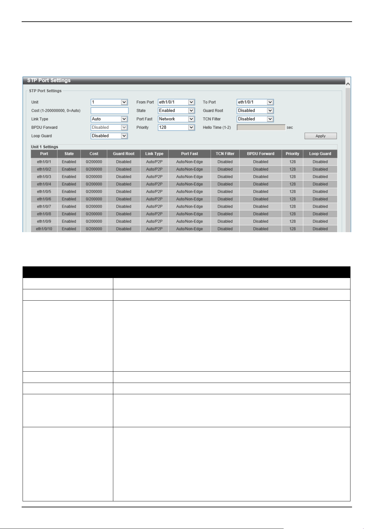
DGS-1520 Series Gigabit Ethernet Smart Managed Switch Web UI Reference Guide
163
STP Port Settings
This window is used to display and configure the STP port settings.
To view the following window, click L2 Features > STP > STP Port Settings, as shown below:
Figure 5-55 STP Port Settings Window
The fields that can be configured are described below:
Parameter Description
Unit
Select the Switch unit that will be used for this configuration here.
From Port - To Port
Select the range of ports that will be used for this configuration here.
Cost
Enter the cost value here. This value must be between 1 and 200000000. This
value defines a metric that indicates the relative cost of forwarding packets to the
specified port list. Port cost can be set automatically or as a metric value. By
default, this value is 0 (auto). Setting 0 for the external cost will automatically set
the speed for forwarding packets to the specified port(s) in the list for optimal
efficiency.
By default, port cost for 10 Mbps is 2000000, 100 Mbps is 200000, 1Gbps is
20000, 2.5Gbps is 8000, and 10Gbps is 2000. The lower the number, the greater
the probability the port will be chosen to forward packets.
State
Select to enable or disable the STP port state.
Guard Root
Select to enable or disable the Guard Root function.
Link Type Select the link type here. Options to choose from are Auto, P2P, and Shared. A
full-duplex port is considered to have a Point-to-Point (P2P) connection. The port
cannot transit into the forwarding state rapidly by setting the link type to Shared.
By default, the Auto option is used.
Port Fast
Select the Port Fast option here. Options to choose from are:
• Network - The port will remain in the non-port-fast state for three seconds.
The port will change to the port-fast state if no BPDU is received and
changes to the forwarding state. If the port received the BPDU later, it will
change to the non-port-fast state.
• Disable - The port will always be in the non-port-fast state. It will always
wait for the forward-time delay to change to the forwarding state.
• Edge - The port will directly change to the spanning-tree forwarding state
when a link-up occurs without waiting for the forward-time delay. If the

DGS-1520 Series Gigabit Ethernet Smart Managed Switch Web UI Reference Guide
164
Parameter Description
interface receives a BPDU later, its operation state changes to the non-port-
fast state.
By default, the Network option is used.
TCN Filter
Select to enable or disable the TCN Filter option. When a port is set to the TCN
filter mode, the TC event received by the port will be ignored. By default, this
option is disabled.
BPDU Forward
Select to enable or disable BPDU forwarding. If enabled, the received STP BPDU
will be forwarded to all VLAN member ports in the untagged form. By default, this
option is disabled.
Priority
Select the priority value here. Options to choose from are 0 to 240. By default, this
value is 128. A lower value has higher priority.
Hello Time
Enter the hello time value here. This value must be between 1 and 2 seconds. This
value specifies the interval that a designated port will wait between the periodic
transmissions of each configuration message.
Loop Guard
Select to enable or disable the Loop Guard feature on the specified port(s) here.
The STP Loop Guard feature provides additional protection against Layer 2
forwarding loops (STP loops). An STP loop is created when an STP blocking port
in a redundant topology erroneously transitions to the Forwarding state. This
usually happens because one of the ports in a physically redundant topology (not
necessarily the STP blocking port) no longer receives STP BPDUs. In its
operation, STP relies on continuous reception or transmission of BPDUs based on
the port role. The designated port transmits BPDUs, and the non-designated port
receives BPDUs.
When one of the ports in a physically redundant topology no longer receives
BPDUs, the STP considers the topology to be loop free. Eventually, an alternate
port that was previously a Blocking or Backup port becomes Designated and
moves to a Forwarding state. This situation creates a loop.
Click the Apply button to accept the changes made.

DGS-1520 Series Gigabit Ethernet Smart Managed Switch Web UI Reference Guide
165
MST Configuration Identification
This window is used to display and configure the MST configuration identification settings. These settings will uniquely
identify an MSTI configured on the Switch. The Switch initially possesses one Common Internal Spanning Tree (CIST)
of which the user may modify the parameters for but cannot change or delete the MSTI ID.
To view the following window, click L2 Features > STP > MST Configuration Identification, as shown below:
Figure 5-56 MST Configuration Identification Window
The fields that can be configured for MST Configuration Identification are described below:
Parameter Description
Configuration Name
Enter the MST. This name uniquely identifies the MSTI (Multiple Spanning Tree
Instance). If a Configuration Name is not set, this field will show the MAC address
to the device running MSTP.
Revision Level
Enter the revision level value here. This value must be between 0 and 65535. By
default, this value is 0. This value, along with the Configuration Name, identifies
the MSTP region configured on the Switch.
Click the Apply button to accept the changes made.
In the Private VLAN Synchronize section, the user can click the Apply button to synchronize the private VLANs.
The fields that can be configured for Instance ID Settings are described below:
Parameter Description
Instance ID
Enter the instance ID here. This value must be between 1 and 64.
Action Select the action that will be taken here. Options to choose from are Add VID and
Remove VID.
VID List
Enter the VID list value here. This field is used to specify the VID range from
configured VLANs set on the Switch.
Click the Apply button to accept the changes made.
Click the Edit button to re-configure the specific entry.
Click the Delete button to remove the specific entry.
Enter a page number and click the Go button to navigate to a specific page when multiple pages exist.
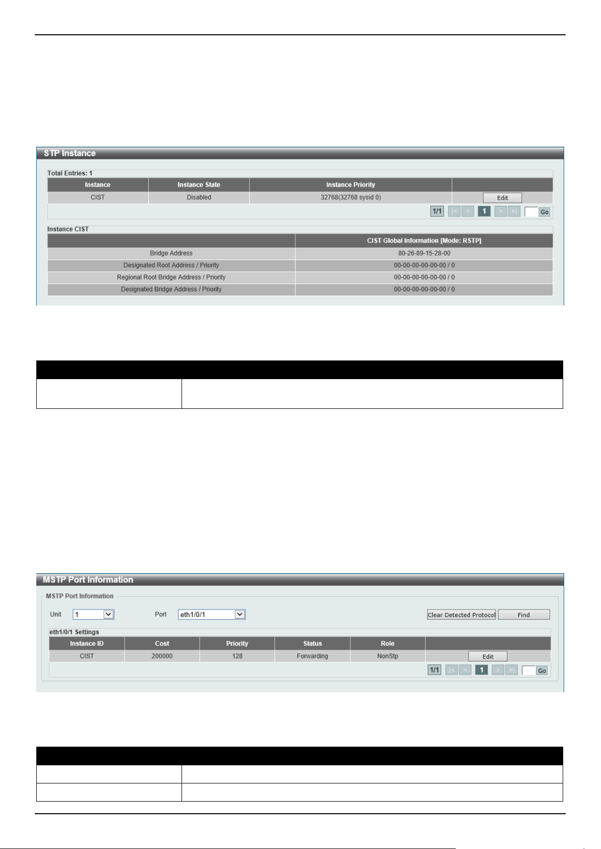
DGS-1520 Series Gigabit Ethernet Smart Managed Switch Web UI Reference Guide
166
STP Instance
This window is used to display and configure the STP instance settings.
To view the following window, click L2 Features > STP > STP Instance, as shown below:
Figure 5-57 STP Instance Window
The fields that can be configured are described below:
Parameter Description
Instance Priority After clicking the Edit button, enter the Instance Priority value here. The range is
from 0 to 61440.
Click the Edit button to re-configure the specific entry.
Click the Apply button to accept the changes made.
Enter a page number and click the Go button to navigate to a specific page when multiple pages exist.
MSTP Port Information
This window is used to display and configure the MSTP port information settings.
To view the following window, click L2 Features > STP > MSTP Port Information, as shown below:
Figure 5-58 MSTP Port Information Window
The fields that can be configured are described below:
Parameter Description
Unit
Select the Switch unit that will be used for this display here.
Port
Select the port number that will be cleared here.
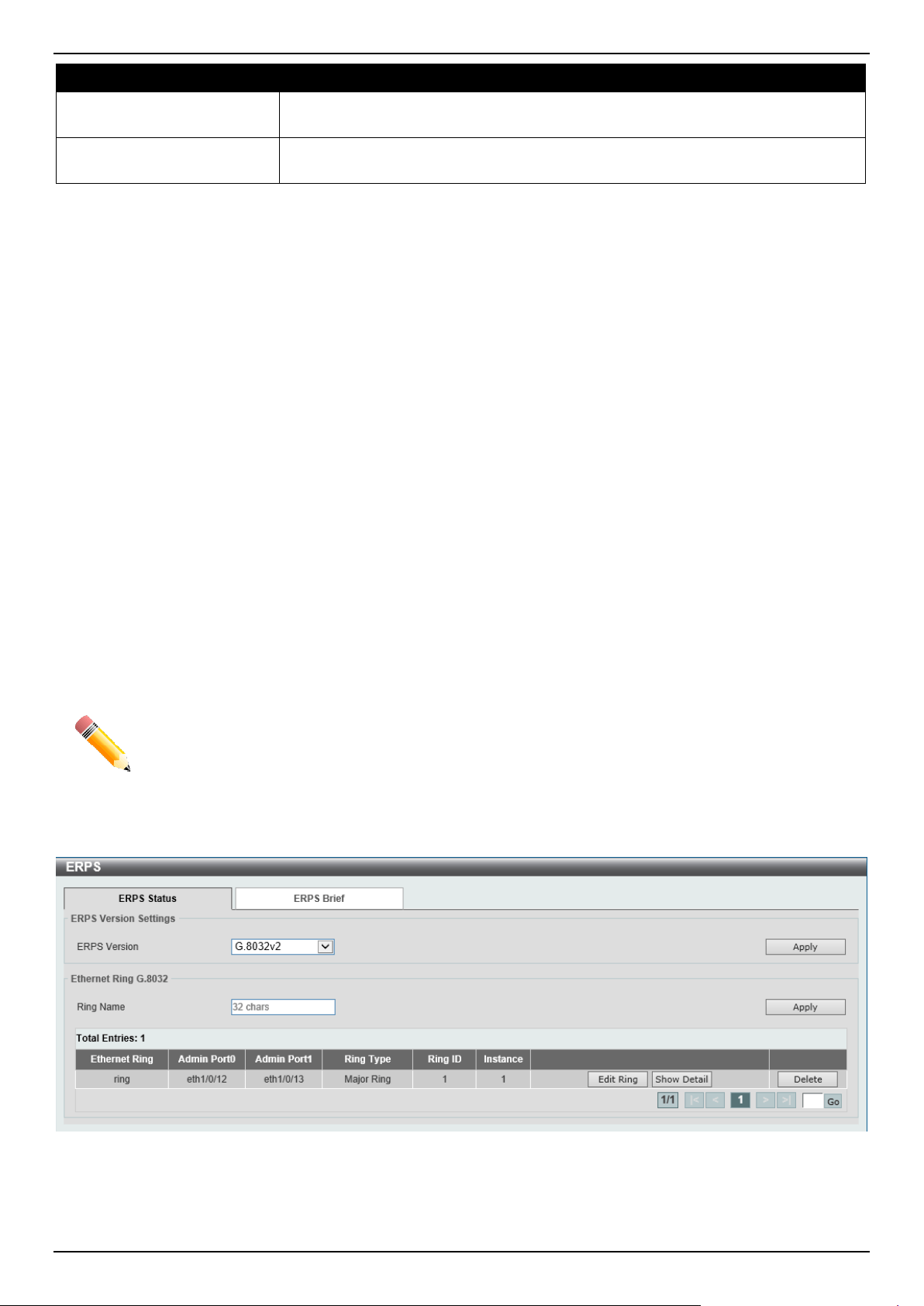
DGS-1520 Series Gigabit Ethernet Smart Managed Switch Web UI Reference Guide
167
Parameter Description
Cost After clicking the Edit button, enter the cost value here. This value must be
between 1 and 200000000.
Priority After clicking the Edit button, select the priority value here. Options to choose from
are 0 to 240. By default, this value is 128. A lower value has higher priority.
Click the Clear Detected Protocol button to clear the detected protocol settings for the port selected.
Click the Find button to locate a specific entry based on the information entered.
Click the Edit button to re-configure the specific entry.
Enter a page number and click the Go button to navigate to a specific page when multiple pages exist.
ERPS (G.8032)
Ethernet Ring Protection Switching (ERPS) (ITU-T G.8032) integrates mature Ethernet Operations, Administration,
and Maintenance (OAM) functions and a simple Automatic Protection Switching (APS) protocol to provide sub-50ms
protection for Ethernet traffic in a ring topology. It ensures that there are no loops formed at the Ethernet layer.
One link within a ring will be blocked to avoid a Loop (RPL, Ring Protection Link). When the failure happens,
protection switching blocks the failed link and unblocks the RPL. When the failure clears, protection switching blocks
the RPL again and unblocks the link on which the failure is cleared.
ERPS
This window is used to display and configure the Ethernet Ring Protection Switching (ERPS) settings. STP and
Loopback Detection (LBD) should be disabled on the ring ports before enabling ERPS. The ERPS cannot be enabled
before the R-APS VLAN ring ports, RPL port, and RPL owner are configured.
NOTE: Be aware that changing the ERPS version will lead to the restart of the running protocol.
To view the following window, click L2 Features > ERPS (G.8032) > ERPS and select the ERPS Status tab, as
shown below:
Figure 5-59 ERPS Window

DGS-1520 Series Gigabit Ethernet Smart Managed Switch Web UI Reference Guide
168
The fields that can be configured in ERPS Version Settings are described below:
Parameter Description
ERPS Version Select the ERPS version here. Options to choose from are G.8032v1 and
G.8032v2.
G.8032v2 provides the following functions:
• Supports multi-instance in a physical ring.
• Supports operation commands: manual, force, and clear.
• Supports to configure the sending of the R-APS PDU destination address
with the RING-ID of the physical ring.
Before specifying G.8032v1 for a G.8032v2-running device, delete all ERPS
configurations that G.8032v1 does not support. Otherwise, the version cannot be
changed. Changing the ERPS version will lead to the restart of the running
protocol.
The following configurations will check when to change from G.8032v2 to
G.8032v1:
• Manual switch or force switch command will be cleared.
• The major ring instance and sub-ring instance of the interconnection node
must have different R-APS VLAN IDs.
• In a physical ring, only one instance is supported.
If Ethernet ring nodes running ITU-T G.8032v1 and ITU-T G.8032v2 co-exist on an
Ethernet ring, the following configurations should be made on the G.8032v2
device:
• All physical ring IDs must have the default value of 1.
• The major ring instance and sub-ring instance of the interconnection node
must have different R-APS VLAN IDs.
• Manual switch or force switch command must not exist.
• The physical ring must have only one instance.
Click the Apply button to accept the changes made.
The fields that can be configured in Ethernet Ring G.8032 are described below:
Parameter Description
Ring Name
Enter the Ethernet Ring Protection (ERP) instance name here. This name can be
up to 32 characters long.
Click the Apply button to create an ITU-T G.8032 ERP physical ring.
Click the Edit Ring button to modify an ITU-T G.8032 ERP physical ring.
Click the Show Detail button to view the ITU-T G.8032 ERP physical ring status information.
Click the Delete button to delete the specified ITU-T G.8032 ERP physical ring.
Enter a page number and click the Go button to navigate to a specific page when multiple pages exist.
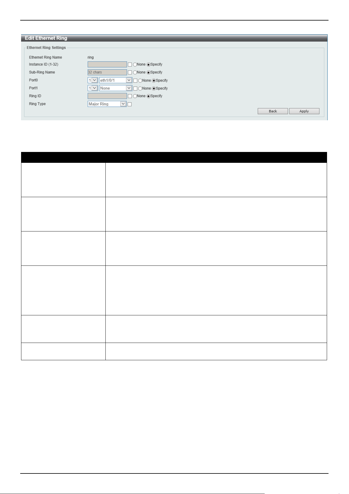
DGS-1520 Series Gigabit Ethernet Smart Managed Switch Web UI Reference Guide
169
After click the Edit Ring button, the following window will appear.
Figure 5-60 ERPS (Edit Ring) Window
The fields that can be configured are described below:
Parameter Description
Instance ID
Select the checkbox and enter the ERP instance number here. This value must be
between 1 and 32.
Select the None radio button to revert this parameter to the default setting.
Select the Specify radio button to configure this parameter as normal.
Sub Ring Name
Select the checkbox and enter the physical ring's sub-ring name here. This name
can be up to 32 characters long.
Select the None radio button to revert this parameter to the default setting.
Select the Specify radio button to configure this parameter as normal.
Port0
Select the checkbox and then select the Switch unit ID and the port number that
will be the first ring port of the physical ring.
Select the None radio button to revert this parameter to the default setting.
Select the Specify radio button to configure this parameter as normal.
Port1
Select the checkbox and then select the Switch unit ID and the port number that
will be the second ring port of the physical ring.
Select the None option, from the drop-down menu, specifies that the inter-
connected node is a local node endpoint of an open ring.
Select the None radio button to revert this parameter to the default setting.
Select the Specify radio button to configure this parameter as normal.
Ring ID
Select the checkbox and enter the ring ID here. The range is from 1 to 239.
Select the None radio button to revert this parameter to the default setting.
Select the Specify radio button to configure this parameter as normal.
Ring Type
Select the checkbox and then select the ring type here. Options to choose from are
Major Ring and Sub-Ring.
Click the Back button to discard the changes made and return to the previous window.
Click the Apply button to accept the changes made.
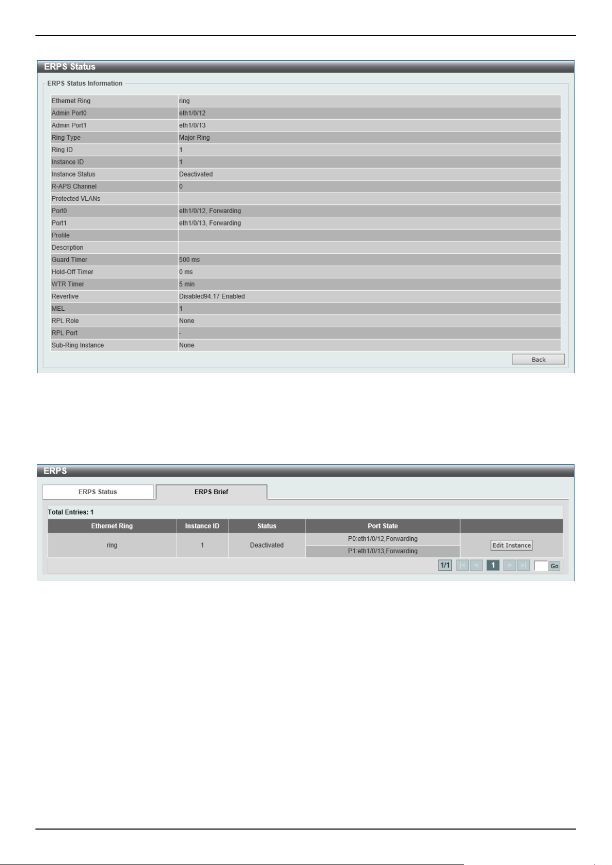
DGS-1520 Series Gigabit Ethernet Smart Managed Switch Web UI Reference Guide
170
After click the Show Detail button, the following window will appear.
Figure 5-61 ERPS (View Detail) Window
Click the Back button to return to the previous window.
To view the following window, select the ERPS Brief tab, as shown below:
Figure 5-62 ERPS (ERPS Brief) Window
Click the Edit Instance button to configure the ERP instance.
Enter a page number and click the Go button to navigate to a specific page when multiple pages exist.
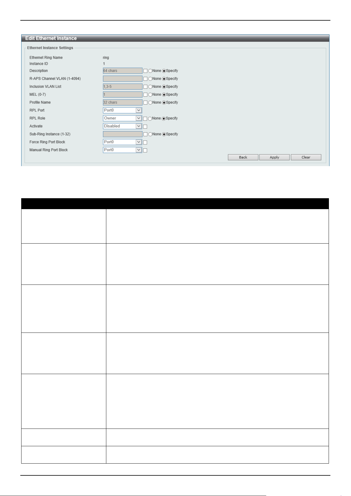
DGS-1520 Series Gigabit Ethernet Smart Managed Switch Web UI Reference Guide
171
After click the Edit Instance button, the following window will appear.
Figure 5-63 ERPS (ERPS Brief, Edit Instance) Window
The fields that can be configured are described below:
Parameter Description
Description
Select the checkbox and enter the ERP instance description here. This description
can be up to 64 characters long.
Select the None radio button to revert this parameter to the default setting.
Select the Specify radio button to configure this parameter as normal.
R-APS Channel VLAN
Select the checkbox and enter the R-APS channel VLAN ID for the ERP instance
here. The APS channel VLAN of a sub-ring instance is also the virtual channel of
the sub-ring. This value must be between 1 and 4094.
Select the None radio button to revert this parameter to the default setting.
Select the Specify radio button to configure this parameter as per normal.
Inclusion VLAN List
Select the checkbox and enter the inclusion VLAN list here. A range is identified
when a hyphen (-) is used. For example, VLANs 1 to 5 can be entered as 1-5. A
list is identified when commas (,) are used. For example, use VLANs 1,3,5. The
VLANs specified here will be protected by the ERP mechanism.
Select the None radio button to revert this parameter to the default setting.
Select the Specify radio button to configure this parameter as normal.
MEL
Select the checkbox and enter the ring MEL value of the ERP instance here. This
value must be between 0 and 7. The configured MEL value of all ring nodes that
participate in the same ERP instance should be identical.
Select the None radio button to revert this parameter to the default setting.
Select the Specify radio button to configure this parameter as normal.
Profile Name
Select the checkbox and enter the G.8032 profile name here that will be
associated with this ERP instance. Multiple ERP instances can be associated with
the same G.8032 profile. The instances associated with the same profile protect
the same set of VLANs, or the VLANs protected by one instance are a subset of
LANs protected by another instance. This name can be up to 32 characters long.
Select the None radio button to revert this parameter to the default setting.
Select the Specify radio button to configure this parameter as normal.
RPL Port
Select the checkbox and then select the RPL port option here. Options to choose
from are Port0 and Port1. The option selected will be configured as the RPL port.
RPL Role
Select the checkbox and then select whether this node is the RPL owner or
neighbor. Options to choose from are Owner and Neighbor.
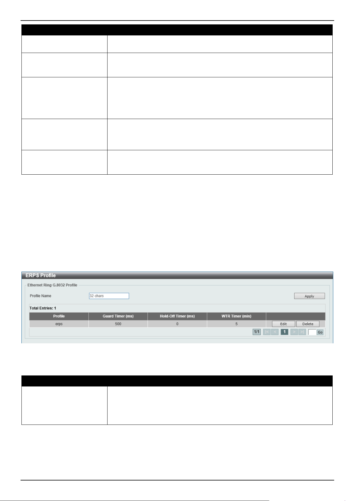
DGS-1520 Series Gigabit Ethernet Smart Managed Switch Web UI Reference Guide
172
Parameter Description
Select the None radio button to revert this parameter to the default setting.
Select the Specify radio button to configure this parameter as normal.
Activate
Select the checkbox and then select whether or not to active this ERP instance.
Options to choose from are Enabled and Disabled. Enabling this option will active
this ERP instance.
Sub Ring Instance
Select the checkbox and enter the identifier of the ERP instance here. This is used
to specify the sub-ring instance of a physical ring instance. The range is from 1 to
32.
Select the None radio button to revert this parameter to the default setting.
Select the Specify radio button to configure this parameter as normal.
Force Ring Port Block
Select the checkbox and select the ERP instance port that will be blocked here.
This forcibly blocks an instance port immediately after force is configured,
irrespective of whether link failures have occurred. Options to choose from are
Port0 and Port1.
Manual Ring Port Block
Select the checkbox and select the ERP instance port that will be blocked here.
This forcibly blocks a port on which MS is configured when link failures and FS
conditions are absent. Options to choose from are Port0 and Port1.
Click the Back button to discard the changes made and return to the previous window.
Click the Apply button to accept the changes made.
Click the Clear button to clear the forced or manual configuration associated with this entry.
ERPS Profile
This window is used to display and configure the Ethernet Ring G.8032 Profile settings.
To view the following window, click L2 Features > ERPS (G.8032) > ERPS Profile, as shown below:
Figure 5-64 ERPS Profile Window
The fields that can be configured are described below:
Parameter Description
Profile Name
Enter the G.8032 profile name here. This name can be up to 32 characters long.
Multiple ERP instances can be associated with the same G.8032 profile. The
instances associated with the same profile protect the same set of VLANs, or the
VLANs protected by one instance are a subset of LANs protected by another
instance.
Click the Apply button to associate the G.8032 profile with the ERP instance created.
Click the Edit button to modify the specified G.8032 profile.
Click the Delete button to disassociate the G.8032 profile.
Enter a page number and click the Go button to navigate to a specific page when multiple pages exist.
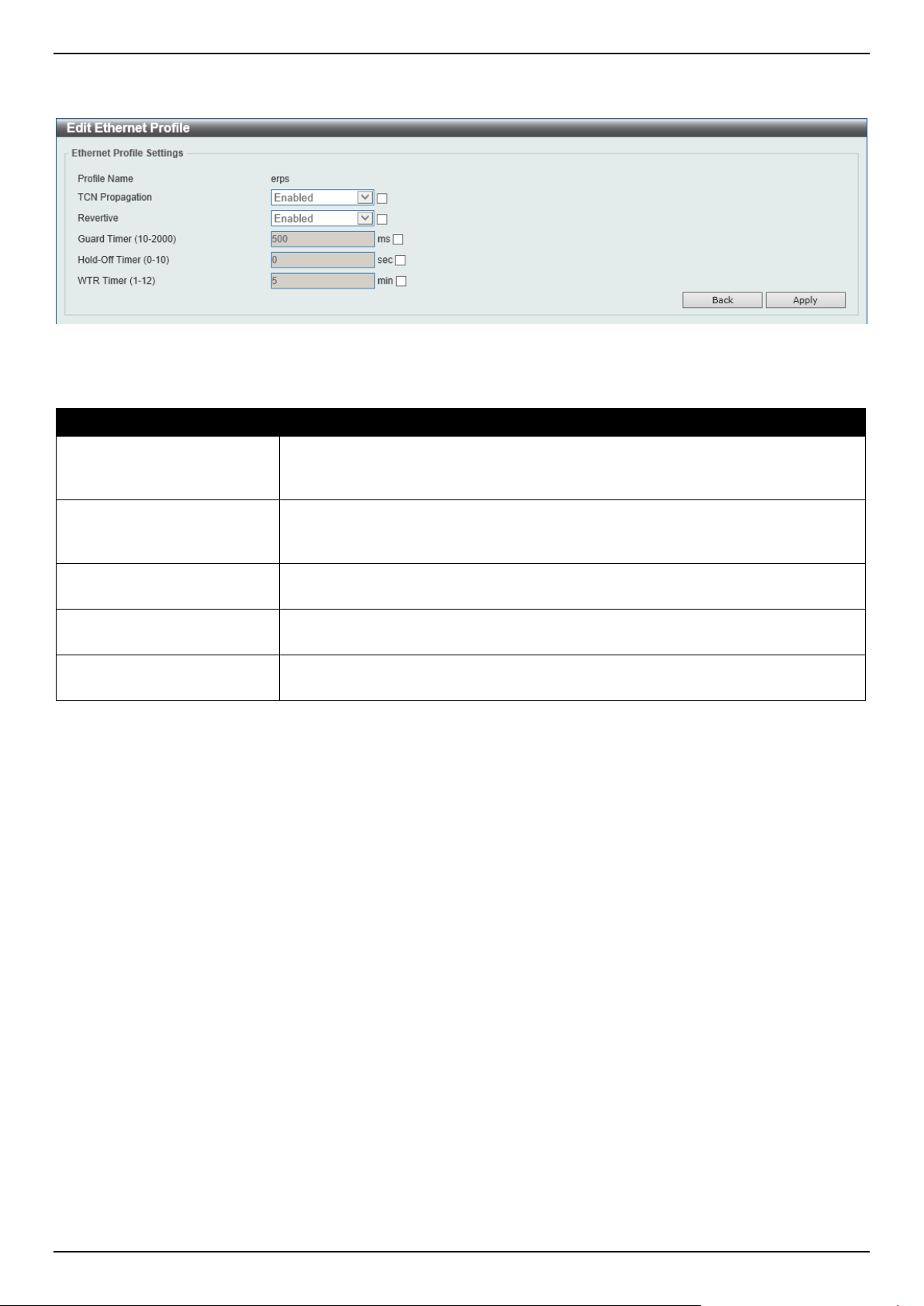
DGS-1520 Series Gigabit Ethernet Smart Managed Switch Web UI Reference Guide
173
After click the Edit button, the following window will appear.
Figure 5-65 ERPS Profile (Edit) Window
The fields that can be configured are described below:
Parameter Description
TCN Propagation
Select the checkbox and then select the TCN propagation state. Options to choose
from are Enable and Disabled. This function is used to enable the propagation of
the topology change notifications from the sub-ERP instance to the major instance.
Revertive
Select the checkbox and then select the revertive state. Options to choose from
are Enable and Disabled. This function is used to revert back to the working
transport entity, for example, when the RPL is blocked.
Guard Timer
Select the checkbox and enter the guard timer value here. This value must be
between 10 and 2000 milliseconds. By default, this value is 500 milliseconds.
Hold-Off Timer
Select the checkbox and enter hold-off timer value here. This value must be
between 0 and 10 seconds. By default, this value is 0 seconds.
WTR Timer
Select the checkbox and enter the Wait To Restore (WTR) timer value here. This
value must be between 1 and 12 minutes. By default, this value is 5 minutes.
Click the Back button to discard the changes made and return to the previous window.
Click the Apply button to accept the changes made.
Loopback Detection
The Loopback Detection (LBD) function is used to detect the loop created by a specific port. This feature is used to
temporarily shut down a port on the Switch when a CTP (Configuration Testing Protocol) packet has been looped
back to the Switch. When the Switch detects CTP packets received from a port or a VLAN, this signifies a loop on the
network. The Switch will automatically block the port or the VLAN and send an alert to the administrator. The
Loopback Detection port will restart (change to normal state) when the Loopback Detection Recover Time times out.

DGS-1520 Series Gigabit Ethernet Smart Managed Switch Web UI Reference Guide
174
The Loopback Detection function can be implemented on a range of ports at a time. The user may enable or disable
this function using the drop-down menu.
To view the following window, click L2 Features > Loopback Detection, as shown below:
Figure 5-66 Loopback Detection Window
The fields that can be configured in Loopback Detection Global Settings are described below:
Parameter Description
Loopback Detection State
Select to enable or disable loopback detection. By default, this option is disabled.
Mode Select the loopback detection mode. Options to choose from are Port-based and
VLAN-based.
Enabled VLAN ID List Enter the VLAN ID for loop detection. This only takes effect when VLAN-based is
selected in the Mode drop-down list.
Interval
Enter the interval in seconds that the device will use to transmit Configuration Test
Protocol (CTP) packets to detect a loopback event. The range is from 1 to 32767
seconds. By default, this value is 10 seconds.
Trap State
Select to enable or disable the loopback detection trap state.
Action Mode
Select the action mode here. Option to choose from are:
• Shutdown - Specifies to shut down the port in the port-based mode or block
traffic on the specific VLAN in the VLAN-based mode when a loop has been
detected.
• None - Specifies not to shut down the port in the port-based mode or block
traffic on the specific VLAN in the VLAN-based mode when a loop has been
detected.
Address Type Select the address type here. Options to choose from are Multicast and
Broadcast.
Click the Apply button to accept the changes made.
The fields that can be configured in Loopback Detection Port Settings are described below:
Parameter Description
Unit
Select the Switch unit that will be used for this configuration here.
From Port - To Port
Select the appropriate port range used for the configuration here.
State
Select this option to enable or disable the state of the port.
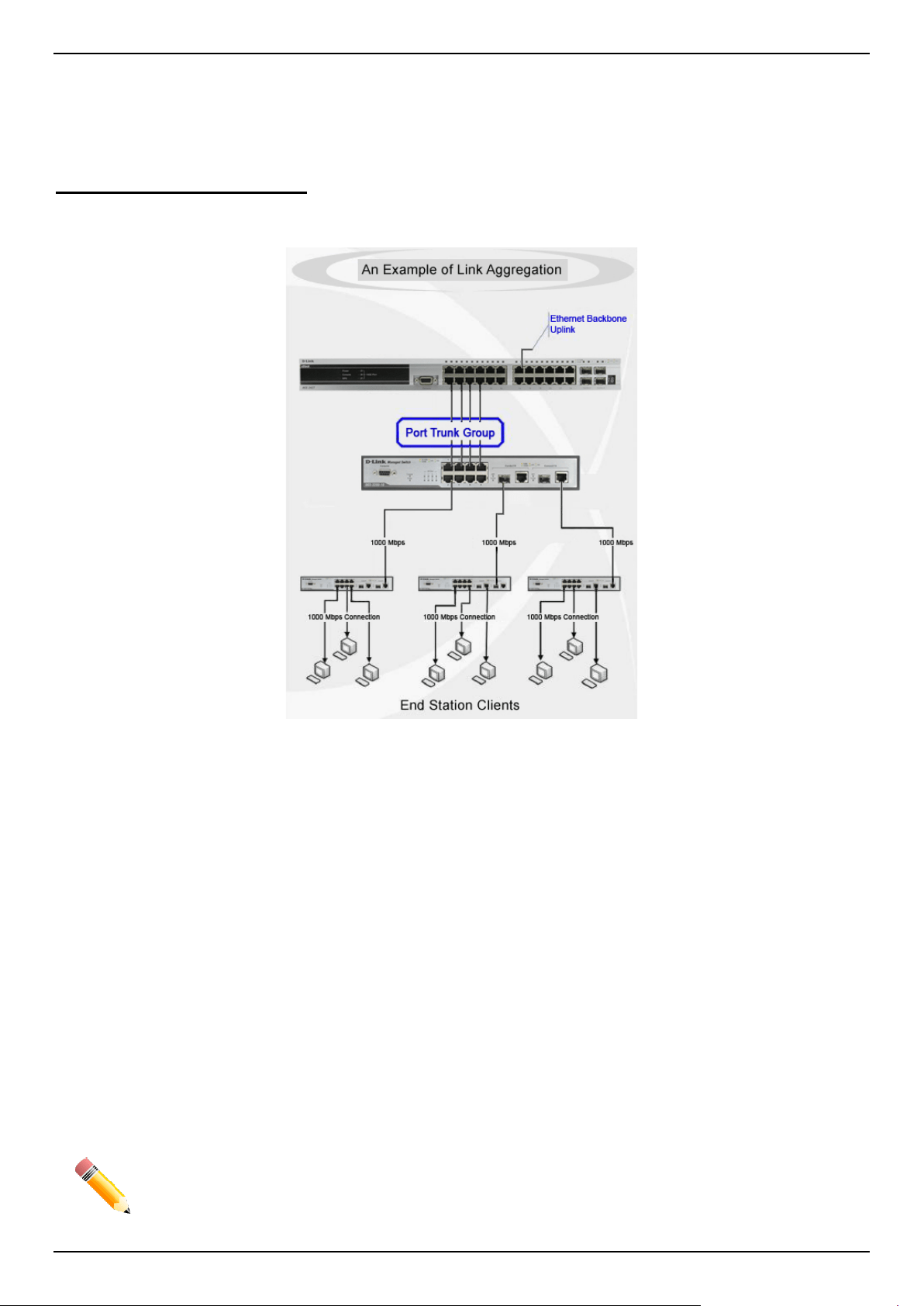
DGS-1520 Series Gigabit Ethernet Smart Managed Switch Web UI Reference Guide
175
Click the Apply button to accept the changes made.
Link Aggregation
Understanding Port Trunk Groups
Port trunk groups are used to combine a number of ports together to make a single high-bandwidth data pipeline. The
Switch supports up to 32 port trunk groups with up to 8 ports in each group.
Figure 5-67 Example of Port Trunk Group
The Switch treats all ports in a trunk group as a single port. Data transmitted to a specific host (destination address)
will always be transmitted over the same port in a trunk group. This allows packets in a data stream to arrive in the
same order they were sent.
Link aggregation allows several ports to be grouped together and to act as a single link. This results in a bandwidth
that is a multiple of a single link's bandwidth. Link aggregation is most commonly used to link bandwidth intensive
network devices, such as servers, to the backbone of a network.
The Switch allows the creation of up to 32 link aggregation groups, each group consisting of up to 8 links (ports). Each
port can only belong to a single link aggregation group. Load balancing is automatically applied to the ports in the
aggregated group, and a link failure within the group causes the network traffic to be directed to the remaining links in
the group.
The Spanning Tree Protocol will treat a link aggregation group as a single link. If two redundant link aggregation
groups are configured on the Switch, STP will block one entire group; in the same way, STP will block a single port
that has a redundant link.
NOTE: If any ports within the trunk group become disconnected, packets intended for the
disconnected port will be load shared among the other linked ports of the link aggregation
group.
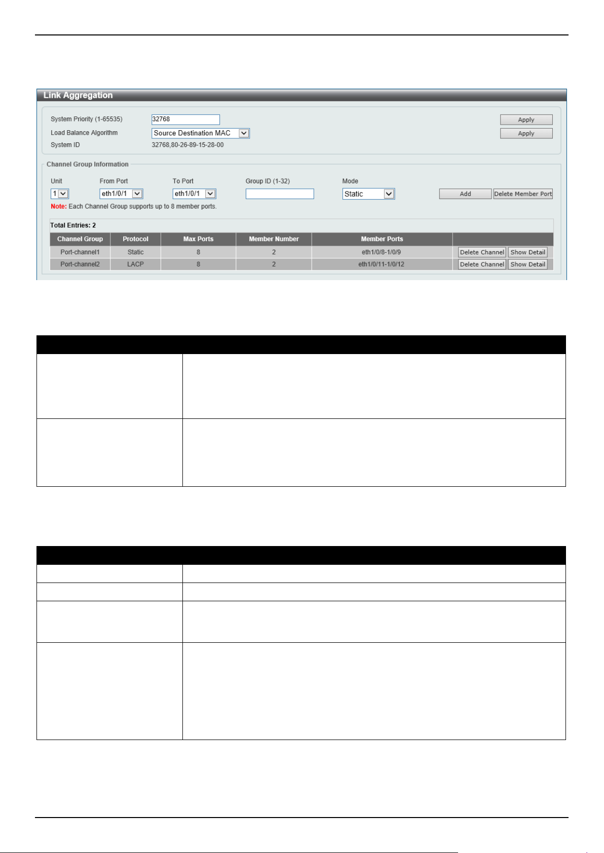
DGS-1520 Series Gigabit Ethernet Smart Managed Switch Web UI Reference Guide
176
This window is used to display and configure the link aggregation settings. To view the following window, click L2
Features > Link Aggregation, as shown below:
Figure 5-68 Link Aggregation Window
The fields that can be configured for Link Aggregation are described below:
Parameter Description
System Priority Enter the system priority value used here. This value must be between 1 and
65535. By default, this value is 32768. The system priority determines which ports
can join a port-channel and which ports are put in the stand-alone mode. The
lower value has a higher priority. If two or more ports have the same priority, the
port number determines the priority.
Load Balance Algorithm
Select the load-balancing algorithm that will be used here. Options to choose from
are Source MAC, Destination MAC, Source Destination MAC, Source IP,
Destination IP, Source Destination IP, Source L4 Port, Destination L4 Port,
and Source Destination L4 Port.
By default, the Source Destination MAC option is used.
Click the Apply button to accept the changes made.
The fields that can be configured for Channel Group Information are described below:
Parameter Description
Unit
Select the Switch unit that will be used for this configuration here.
From Port - To Port
Select the list of ports that will be associated with this configuration here.
Group ID Enter the channel group number here. This value must be between 1 and 32. The
system will automatically create the port-channel when a physical port first joins a
channel group. An interface can only join one channel-group.
Mode Select the mode option here. Options to choose from are Static, Active, and
Passive.
If the mode Static is specified, the channel group type is static.
If the mode Active or Passive is specified, the channel group type is LACP.
A channel group can only consist of either static members or LACP members.
Once the type of channel group has been determined, other types of interfaces
cannot join the channel group.
Click the Add button to add a new channel group.
Click the Delete Member Port button, to delete the member port(s) specified from the group.
Click the Delete Channel button to delete the specified channel group.
Click the Show Detail button to view detailed information about the channel.
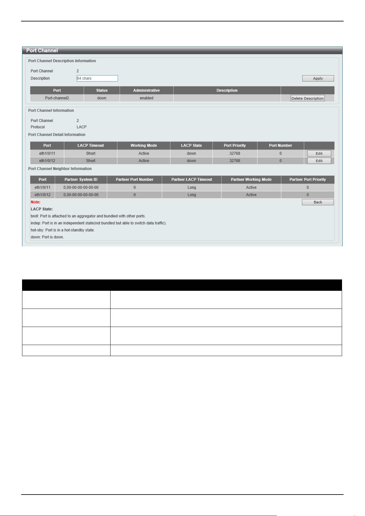
DGS-1520 Series Gigabit Ethernet Smart Managed Switch Web UI Reference Guide
177
After clicking the Show Detail button, the following page will be available.
Figure 5-69 Link Aggregation (Channel Detail) Window
The fields that can be configured are described below:
Parameter Description
Description
Enter the description for the port channel here. This string can be up to 64
characters long.
LACP Timeout After clicking the Edit button, select the LACP timeout here. Options to choose
from are Static and Long.
Working Mode After clicking the Edit button, select the working mode here. Options to choose
from are Active and Passive.
Port Priority
Enter the port priority value here.
Click the Apply button to accept the changes made.
Click the Delete Description button to delete the description for the port channel.
Click the Edit button to re-configure the specific entry.
Click the Back button to return to the previous page.
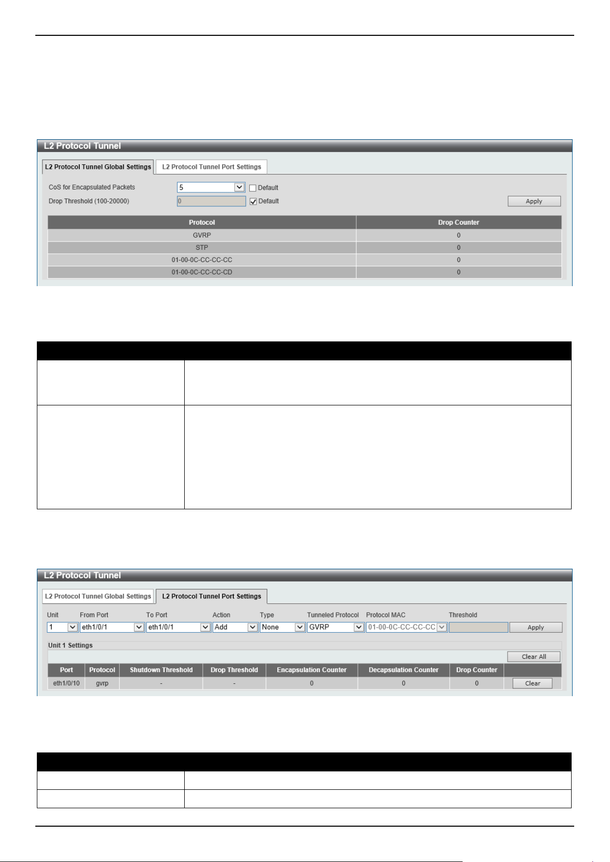
DGS-1520 Series Gigabit Ethernet Smart Managed Switch Web UI Reference Guide
178
L2 Protocol Tunnel
This window is used to display and configure the Layer 2 protocol tunnel settings.
To view the following window, click L2 Features > L2 Protocol Tunnel and select the L2 Protocol Tunnel Global
Settings tab, as shown below:
Figure 5-70 L2 Protocol Tunnel (L2 Protocol Tunnel Global Setting) Window
The fields that can be configured are described below:
Parameter Description
CoS for Encapsulated
Packets
Select the CoS value for encapsulated packets here. This value is between 0 and
7.
Select the Default option to use the default value.
Drop Threshold
Enter the drop threshold value here. This value must be between 100 and 20000.
By default, this value is 0. The tunneling of the Layer 2 protocol packets will
consume CPU processing power in encapsulating, decapsulating, and forwarding
of the packet. Use this option to restrict the CPU processing bandwidth consumed
by specifying a threshold on the number of all Layer 2 protocol packets that can be
processed by the system. When the maximum number of packets is exceeded, the
excessive protocol packets are dropped.
Select the Default option to use the default value.
Click the Apply button to accept the changes made.
To view the following window, select the L2 Protocol Tunnel Port Setting tab, as shown below:
Figure 5-71 L2 Protocol Tunnel (L2 Protocol Tunnel Port Setting) Window
The fields that can be configured are described below:
Parameter Description
Unit
Select the Switch unit that will be used for this configuration here.
From Port - To Port
Select the range of ports that will be used for this configuration here.
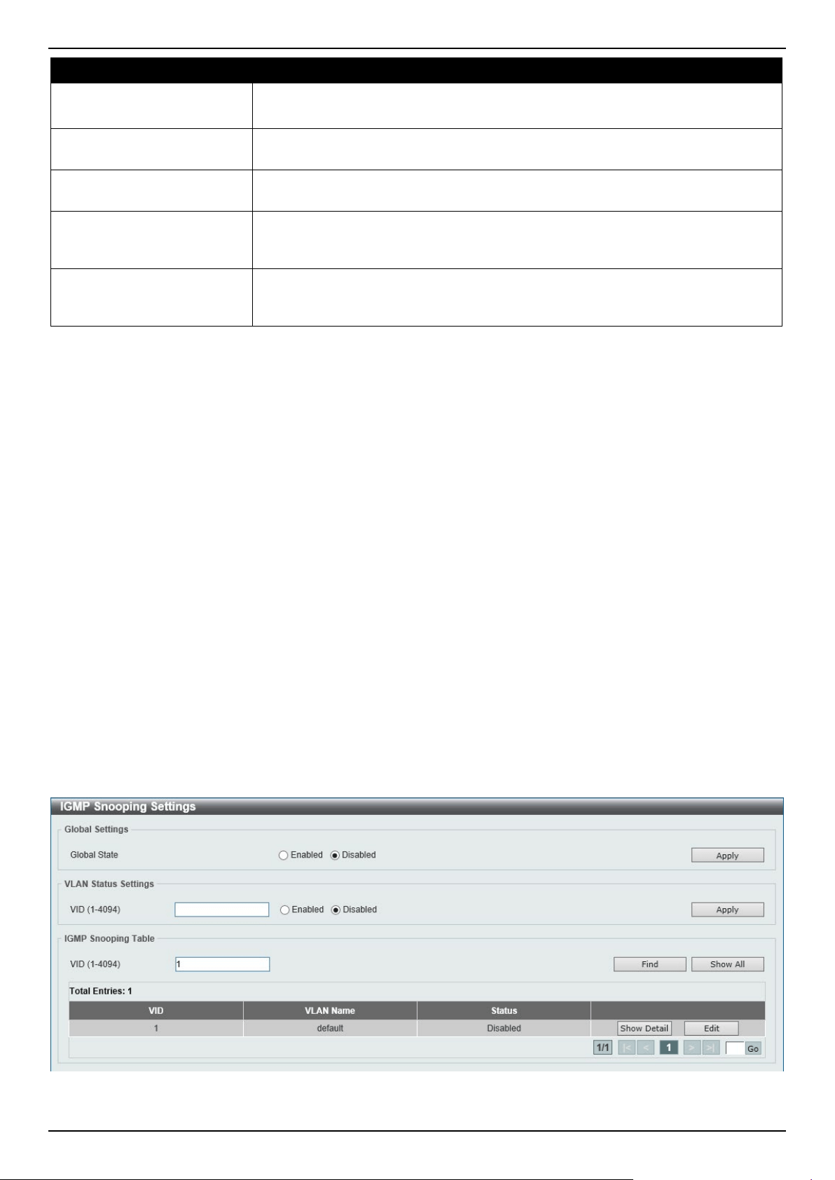
DGS-1520 Series Gigabit Ethernet Smart Managed Switch Web UI Reference Guide
179
Parameter Description
Action Select Add to add a new entry based in the information entered.
Select Delete to delete an entry based in the information entered.
Type Select the type option here. Options to choose from are None, Shutdown, and
Drop.
Tunneled Protocol Select the tunneled protocol option here. Options to choose from are GVRP, STP,
Protocol MAC, and All.
Protocol MAC After selecting the Protocol MAC option as the Tunneled Protocol, the following
option will be available. Select the protocol MAC option here. Options to choose
from are 01-00-0C-CC-CC-CC and 01-00-0C-CC-CC-CD.
Threshold After selecting the Shutdown or Drop option in the Type field, the following
parameter will be available. Enter the threshold value here. This value must be
between 1 and 4096.
Click the Apply button to accept the changes made.
Click the Clear All button to clear all the counter information.
Click the Clear button to clear all the counter information of the specific entry.
L2 Multicast Control
IGMP Snooping
Internet Group Management Protocol (IGMP) snooping allows the Switch to recognize IGMP queries and reports sent
between network stations or devices and an IGMP host.
IGMP Snooping Settings
In order to use IGMP Snooping it must first be enabled for the entire Switch under IGMP Global Settings at the top of
the window. You may then fine-tune the settings for each VLAN by clicking the corresponding Edit button. When
enabled for IGMP snooping, the Switch can open or close a port to a specific multicast group member based on IGMP
messages sent from the device to the IGMP host or vice versa. The Switch monitors IGMP messages and
discontinues forwarding multicast packets when there are no longer hosts requesting that they continue.
To view the following window, click L2 Features > L2 Multicast Control > IGMP Snooping > IGMP Snooping
Settings, as shown below:
Figure 5-72 IGMP Snooping Settings Window
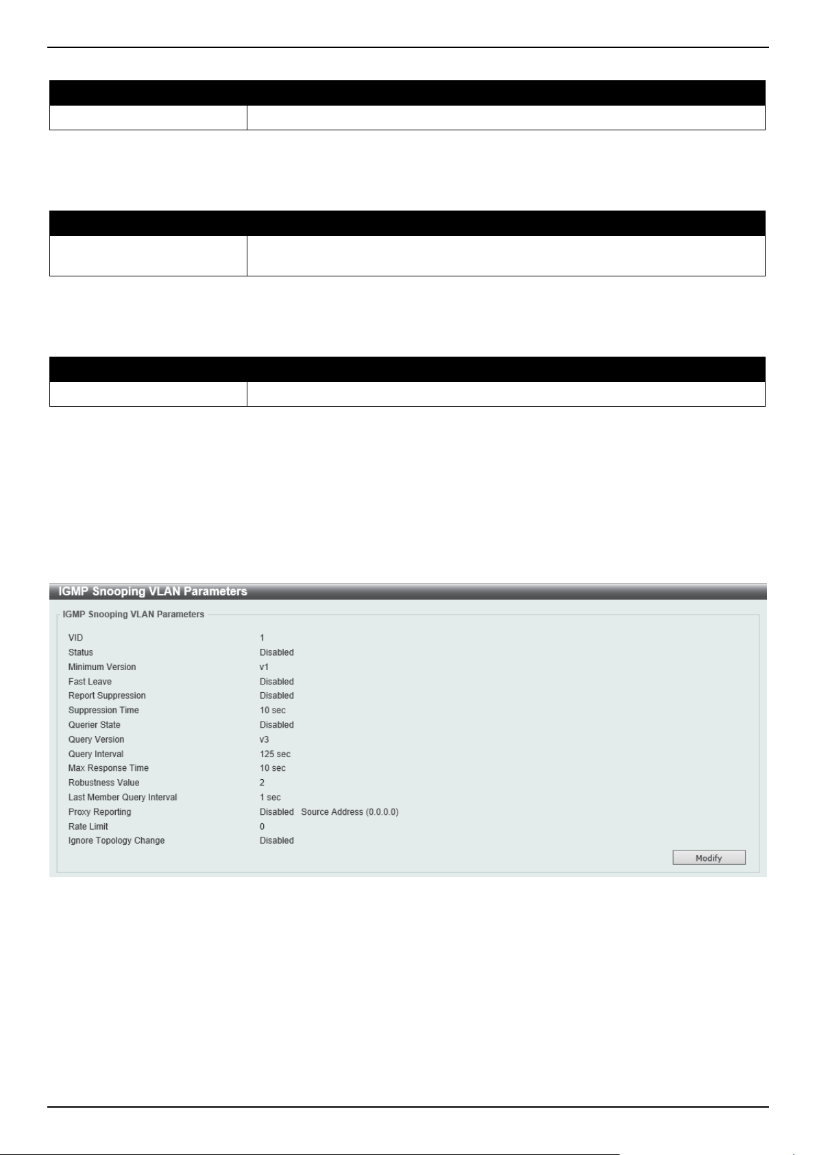
DGS-1520 Series Gigabit Ethernet Smart Managed Switch Web UI Reference Guide
180
The fields that can be configured in Global Settings are described below:
Parameter Description
Global State
Select this option to globally enable or disable IGMP snooping.
Click the Apply button to accept the changes made.
The fields that can be configured in VLAN Status Settings are described below:
Parameter Description
VID
Enter a VLAN ID from 1 to 4094, and select to enable or disable IGMP snooping
on the VLAN.
Click the Apply button to accept the changes made.
The fields that can be configured in IGMP Snooping Table are described below:
Parameter Description
VID
Enter a VLAN ID from 1 to 4094.
Click the Find button to locate a specific entry based on the information entered.
Click the Show All button to view all the entries.
Click the Show Detail button to see the detail information of the specific VLAN.
Click the Edit button to re-configure the specific entry.
Enter a page number and click the Go button to navigate to a specific page when multiple pages exist.
After clicking the Show Detail button, the following window will appear.
Figure 5-73 IGMP Snooping Settings (Show Detail) Window
The window displays the detail information about IGMP snooping VLAN.
Click the Modify button to edit the information in the following window.
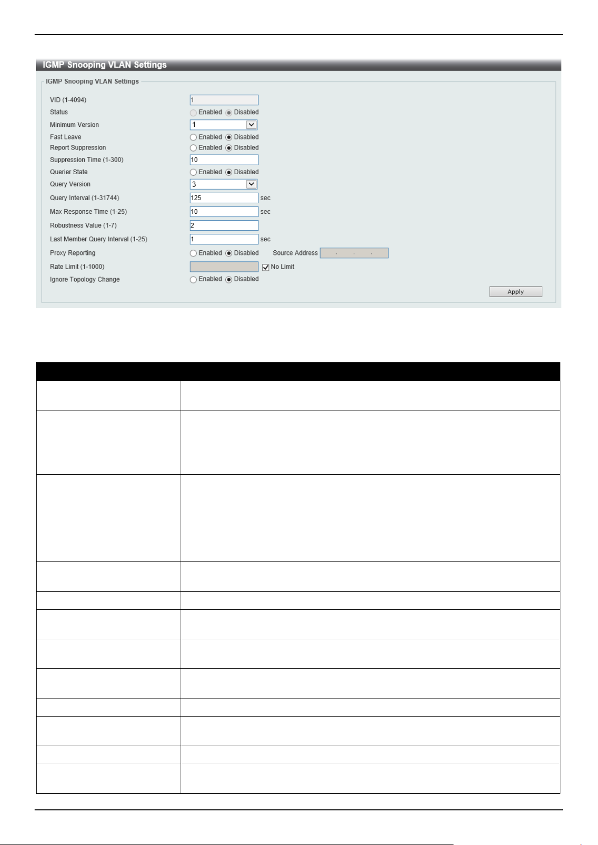
DGS-1520 Series Gigabit Ethernet Smart Managed Switch Web UI Reference Guide
181
After clicking the Modify or Edit button in IGMP Snooping Settings window, the following window will appear.
Figure 5-74 IGMP Snooping Settings (Modify, Edit) Window
The fields that can be configured are described below:
Parameter Description
Minimum Version
Select the minimum IGMP host version that is allowed on the VLAN. Options to
choose from are 1, 2, and 3.
Fast Leave
Select this option to enable or disable the IGMP snooping Fast Leave function. If
enabled, the membership is immediately removed when the system receives the
IGMP done message from the last member. When fast leave is enabled, the
Switch will not generate specific queries. When fast leave is disabled, the Switch
will generate specific queries.
Report Suppression
Select this option to enable or disable the report suppression. The report
suppression function only works for IGMPv1 and IGMPv2 traffic. When report
suppression is enabled, the Switch suppresses the duplicate reports sent by hosts.
The suppression for the same group report or leave will continue until the
suppression time expires. For report or leave messages to the same group, only
one report or leave message is forwarded. The remaining report and leave
messages are suppressed.
Suppression Time
Enter the interval of suppressing duplicate IGMP reports or leaves. The range is
from 1 to 300.
Querier State
Select this option to enable or disable the querier state.
Query Version
Select the general query packet version sent by the IGMP snooping querier.
Options to choose from are 1, 2, and 3.
Query Interval
Enter the interval at which the IGMP snooping querier sends IGMP general query
messages periodically. The range is from 1 to 31744.
Max Response Time
Enter the maximum response time, in seconds, advertised in IGMP snooping
queries. The range is from 1 to 25.
Robustness Value
Enter the robustness variable used in IGMP snooping. The range is from 1 to 7.
Last Member Query Interval
Enter the interval at which the IGMP snooping querier sends IGMP group-specific
or group-source-specific (channel) query messages. The range is from 1 to 25.
Proxy Reporting
Select this option to enable or disable the proxy-reporting function.
Source Address Enter the source IP of proxy reporting. This is available when Enabled is selected
in Proxy Reporting.
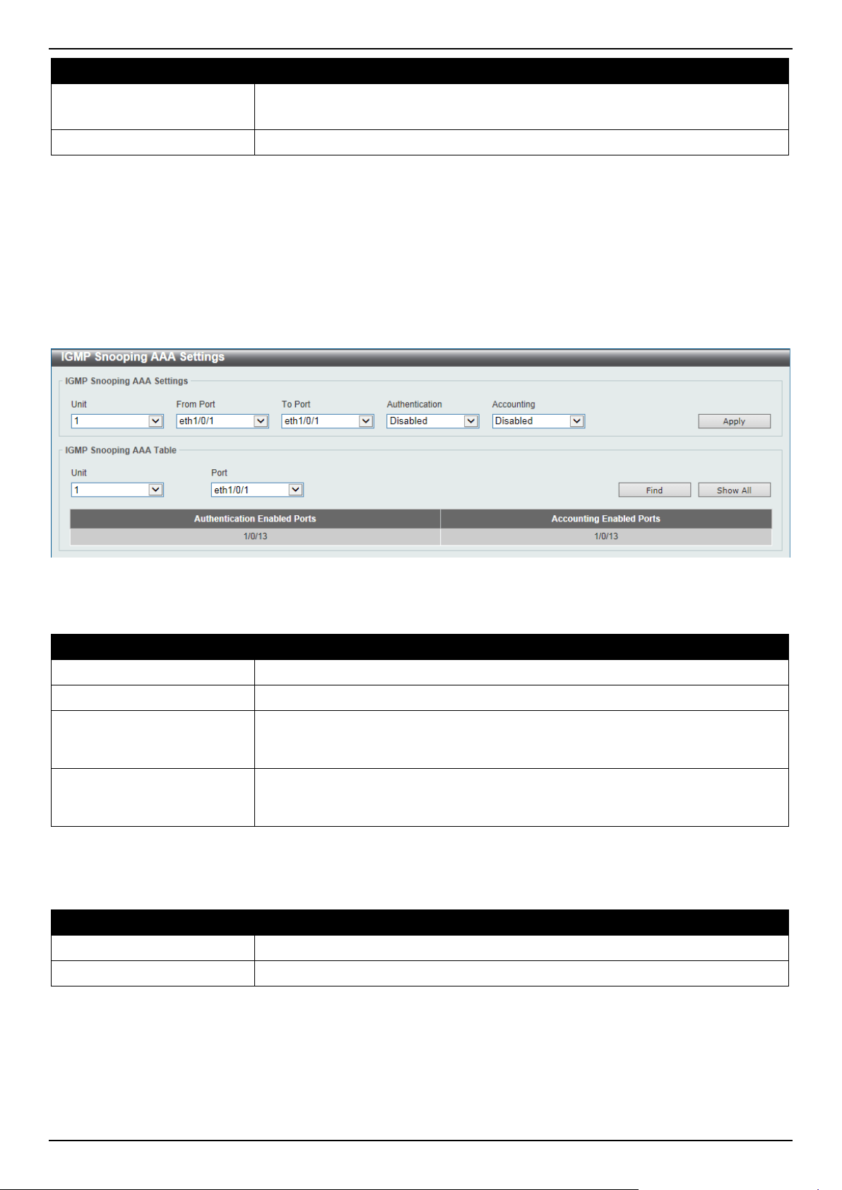
DGS-1520 Series Gigabit Ethernet Smart Managed Switch Web UI Reference Guide
182
Parameter Description
Rate Limit
Enter the rate limit value here. The range is from 1 to 1000.
Tick the No Limit option to apply no rate limit on this profile.
Ignore Topology Change
Select to enable or disable the Ignore Topology Change feature here.
Click the Apply button to accept the changes made.
IGMP Snooping AAA Settings
This window is used to display and configure the IGMP snooping AAA settings.
To view the following window, click L2 Features > L2 Multicast Control > IGMP Snooping > IGMP Snooping AAA
Settings, as shown below:
Figure 5-75 IGMP Snooping AAA Settings Window
The fields that can be configured in IGMP Snooping AAA Settings are described below:
Parameter Description
Unit
Select the Switch unit that will be used for this configuration here.
From Port - To Port
Select the range of ports that will be used for this configuration here.
Authentication
Select to enable or disable authentication here. This is used to enable or disable
the authentication function for IGMP join messages. When enabled and the client
wants to join a group, the system will perform authentication first.
Accounting
Select to enable or disable accounting here. This is used to enable or disable
accounting when a listener joining an IGMP group. When enabled and the client
joins a group, the accounting message will be sent to RADIUS.
Click the Apply button to accept the changes made.
The fields that can be configured in IGMP Snooping AAA Table are described below:
Parameter Description
Unit
Select the Switch unit that will be used for this display here.
From Port - To Port
Select the range of ports that will be used for this display here.
Click the Find button to generate the display based on the selections made.
Click the Show All button to display all the available entries.
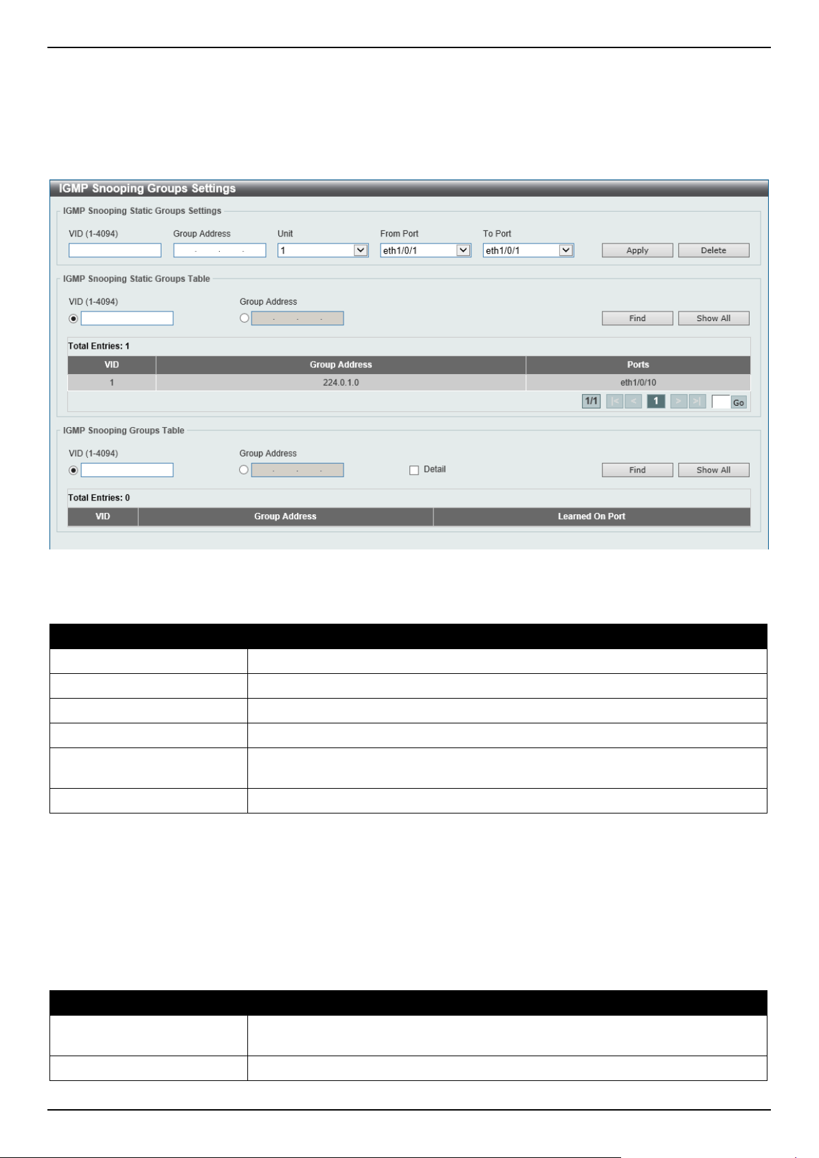
DGS-1520 Series Gigabit Ethernet Smart Managed Switch Web UI Reference Guide
183
IGMP Snooping Groups Settings
This window is used to display and configure the IGMP snooping static group, and view IGMP snooping group.
To view the following window, click L2 Features > L2 Multicast Control > IGMP Snooping > IGMP Snooping
Groups Settings, as shown below:
Figure 5-76 IGMP Snooping Groups Settings Window
The fields that can be configured in IGMP Snooping Static Groups Settings/Table are described below:
Parameter Description
VID
Enter a VLAN ID of the multicast group. The range is from 1 to 4094.
Group Address
Enter an IP multicast group address.
Unit
Select the Switch unit that will be used for this configuration here.
From Port - To Port
Select the appropriate port range used for the configuration here.
VID
Click the radio button and enter a VLAN ID of the multicast group. The range is
from 1 to 4094.
Group Address
Click the radio button and enter an IP multicast group address.
Click the Apply button to accept the changes made.
Click the Delete button to remove the specified entry.
Click the Find button to locate a specific entry based on the information entered.
Click the Show All button to view all the entries.
Enter a page number and click the Go button to navigate to a specific page when multiple pages exist.
The fields that can be configured in IGMP Snooping Groups Table are described below:
Parameter Description
VID
Click the radio button and enter a VLAN ID of the multicast group. The range is
from 1 to 4094.
Group Address
Click the radio button and enter an IP multicast group address.
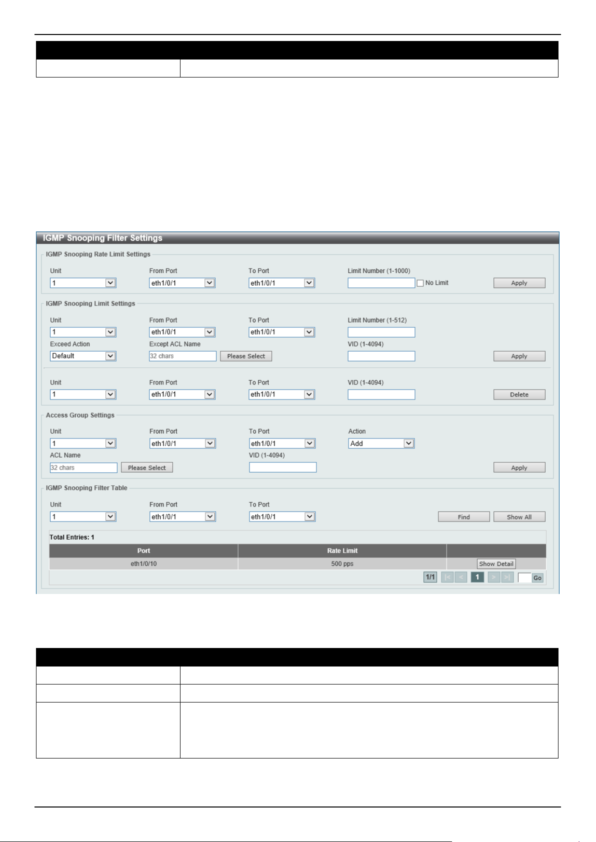
DGS-1520 Series Gigabit Ethernet Smart Managed Switch Web UI Reference Guide
184
Parameter Description
Detail
Select this option to display the IGMP group detail information.
Click the Find button to locate a specific entry based on the information entered.
Click the Show All button to view all the entries.
IGMP Snooping Filter Settings
This window is used to display and configure the IGMP snooping filter settings.
To view the following window, click L2 Features > L2 Multicast Control > IGMP Snooping > IGMP Snooping Filter
Settings, as shown below:
Figure 5-77 IGMP Snooping Filter Settings Window
The fields that can be configured in IGMP Snooping Rate Limit Settings are described below:
Parameter Description
Unit
Select the Switch unit ID that will be used here.
From Port - To Port
Select the Switch port range that will be used here.
Limit Number
Enter the limit number here. This is to configure the rate of IGMP control packets
that the Switch can process on a specific interface. The range is from 1 to 1000
packets per second.
Select the No Limit option to remove the limitation.
Click the Apply button to accept the changes made.

DGS-1520 Series Gigabit Ethernet Smart Managed Switch Web UI Reference Guide
185
The fields that can be configured in IGMP Snooping Limit Settings are described below:
Parameter Description
Unit
Select the Switch unit that will be used for this configuration here.
From Port - To Port
Select the appropriate port range used for the configuration here.
Limit Number
Enter the limit number here. This is used to set the limitation on the number of
IGMP cache entries that can be created. The range is from 1 to 512.
Exceed Action
Select the exceed action here. This parameter specifies the action for handling
newly learned groups when the limitation is exceeded.
Options to choose from are:
• Default - Specifies that the default action will be taken.
• Drop - Specifies that the new group will be dropped.
• Replace - Specifies that the new group will replace the oldest group.
Except ACL Name
Enter the standard IP access list name here. The group (*,G) permitted by the
access list will be excluded from the limit. To permit a group (*,G), specify "any" in
the source address field and G in the destination address field of the access list
entry. This name can be up to 32 characters long.
Alternatively, click the Please Select button to find and select any of the exiting
access lists configured on this Switch to be used in this configuration.
VID
Enter the Layer 2 VLAN name on a trunk port here. This applies the filter to
packets that arrive on that VLAN. The range is from 1 to 4094.
Click the Apply button to accept the changes made.
Click the Delete button to delete an entry based on the information entered.
The fields that can be configured in Access Group Settings are described below:
Parameter Description
Unit
Select the Switch unit that will be used for this configuration here.
From Port - To Port
Select the appropriate port range used for the configuration here.
Action Select Add to add a new entry based in the information entered.
Select Delete to delete an entry based in the information entered.
ACL Name
Enter the standard IP access list name here. This is used to permit users to join a
group (*, G), specify "any" in source address field and G in destination address
field of the access list entry. This name can be up to 32 characters long.
Alternatively, click the Please Select button to find and select any of the exiting
access lists configured on this Switch to be used in this configuration.
VID
Enter the VLAN ID used for this configuration here. The range is from 1 to 4094.
Click the Apply button to accept the changes made.
The fields that can be configured in IGMP Snooping Filter Table are described below:
Parameter Description
Unit
Select the Switch unit ID that will be used here.
From Port - To Port
Select the Switch port range that will be used here.
Click the Find button to locate a specific entry based on the information entered.
Click the Show All button to display all the entries.
Click the Show Detail button to view detailed information associated with the entry.
Enter a page number and click the Go button to navigate to a specific page when multiple pages exist.
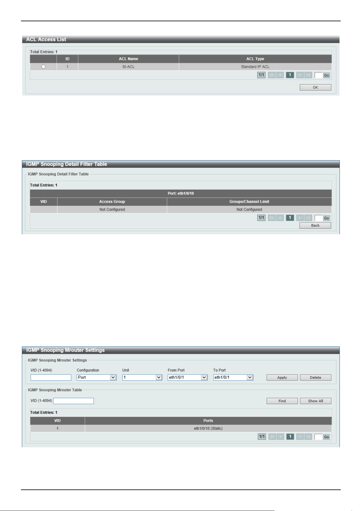
DGS-1520 Series Gigabit Ethernet Smart Managed Switch Web UI Reference Guide
186
After clicking the Please Select button, the following page will appear.
Figure 5-78 IGMP Snooping Filter Settings (Please Select) Window
Select the ACL and click the OK button to use the selected access list.
Enter a page number and click the Go button to navigate to a specific page when multiple pages exist.
After clicking the Show Detail button, the following page will appear.
Figure 5-79 IGMP Snooping Filter Settings (Show Detail) Window
Click the Back button to return to the previous window.
Enter a page number and click the Go button to navigate to a specific page when multiple pages exist.
IGMP Snooping Mrouter Settings
This window is used to display and configure the IGMP Snooping Multicast Router settings.
To view the following window, click L2 Features > L2 Multicast Control > IGMP Snooping > IGMP Snooping
Mrouter Settings, as shown below:
Figure 5-80 IGMP Snooping Mrouter Settings Window
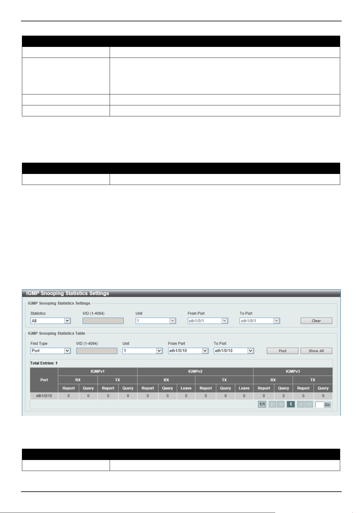
DGS-1520 Series Gigabit Ethernet Smart Managed Switch Web UI Reference Guide
187
The fields that can be configured in IGMP Snooping Mrouter Settings are described below:
Parameter Description
VID
Enter the VLAN ID used here. The range is from 1 to 4094.
Configuration
Select the port configuration. Options to choose from are:
• Port - Select to have the configured ports to be static multicast router ports.
• Forbidden Port - Select to have the configured ports not to be multicast
router ports.
Unit
Select the Switch unit that will be used for this configuration here.
From Port - To Port
Select the appropriate port range used for the configuration here.
Click the Apply button to accept the changes made.
Click the Delete button to remove the specified entry.
The fields that can be configured in IGMP Snooping Mrouter Table are described below:
Parameter Description
VID
Enter the VLAN ID used here. The range is from 1 to 4094.
Click the Find button to locate a specific entry based on the information entered.
Click the Show All button to view all the entries.
Enter a page number and click the Go button to navigate to a specific page when multiple pages exist.
IGMP Snooping Statistics Settings
This window is used to view and clear the IGMP snooping related statistics.
To view the following window, click L2 Features > L2 Multicast Control > IGMP Snooping > IGMP Snooping
Statistics Settings, as shown below:
Figure 5-81 IGMP Snooping Statistics Settings Window
The fields that can be configured in IGMP Snooping Statistics Settings are described below:
Parameter Description
Statistics Select the interface here. Options to choose from are All, VLAN, and Port.

DGS-1520 Series Gigabit Ethernet Smart Managed Switch Web UI Reference Guide
188
Parameter Description
VID Enter a VLAN ID between 1 and 4094. This is available when VLAN is selected in
the Statistics drop-down list.
Unit
Select the Switch unit that will be used for this configuration here. This is available
when Port is selected in the Statistics drop-down list.
From Port - To Port
Select the appropriate port range used for the configuration here. This is available
when Port is selected in the Statistics drop-down list.
Click the Clear button to clear the IGMP snooping related statistics.
The fields that can be configured in IGMP Snooping Statistics Table are described below:
Parameter Description
Find Type Select the interface type. Options to choose from are VLAN, and Port.
VID
Enter a VLAN ID between 1 and 4094.
This is available when VLAN is selected in the Find Type drop-down list.
Unit
Select the Switch unit that will be used for this configuration here.
This is available when Port is selected in the Find Type drop-down list.
From Port - To Port
Select the appropriate port range used for the configuration here.
This is available when Port is selected in the Find Type drop-down list.
Click the Find button to locate a specific entry based on the information entered.
Click the Show All button to view all the entries.
Enter a page number and click the Go button to navigate to a specific page when multiple pages exist.
MLD Snooping
Multicast Listener Discovery (MLD) Snooping is an IPv6 function used similarly to IGMP snooping in IPv4. It is used to
discover ports on a VLAN that are requesting multicast data. Instead of flooding all ports on a selected VLAN with
multicast traffic, MLD snooping will only forward multicast data to ports that wish to receive this data through the use
of queries and reports produced by the requesting ports and the source of the multicast traffic.
MLD snooping is accomplished through the examination of the layer 3 part of an MLD control packet transferred
between end nodes and a MLD router. When the Switch discovers that this route is requesting multicast traffic, it adds
the port directly attached to it into the correct IPv6 multicast table, and begins the process of forwarding multicast
traffic to that port. This entry in the multicast routing table records the port, the VLAN ID, and the associated multicast
IPv6 multicast group address, and then considers this port to be an active listening port. The active listening ports are
the only ones to receive multicast group data.
MLD Control Messages
These types of messages are transferred between devices using MLD snooping. These messages are all defined by
four ICMPv6 packet headers, labeled 130, 131, 132, and 143.
• Multicast Listener Query - Similar to the IGMPv2 Host Membership Query for IPv4, and labeled as 130 in the
ICMPv6 packet header, this message is sent by the router to ask if any link is requesting multicast data. There
are two types of MLD query messages emitted by the router: the General Query, which is used to advertise all
multicast addresses that are ready to send multicast data to all listening ports, and the Multicast Specific query,
which is used to advertise a specific multicast address that is also ready. These two types of messages are
distinguished by a multicast destination address located in the IPv6 header and a multicast address in the
Multicast Listener Query Message.
• Multicast Listener Report, Version 1 - Comparable to the Host Membership Report in IGMPv2, and labeled
as 131 in the ICMP packet header, this message is sent by the listening port to the Switch stating that it is
interested in receiving multicast data from a multicast address in response to the Multicast Listener Query
message.
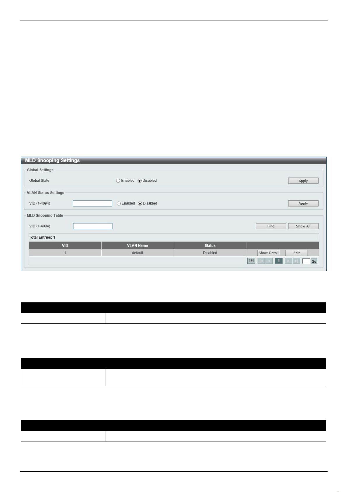
DGS-1520 Series Gigabit Ethernet Smart Managed Switch Web UI Reference Guide
189
• Multicast Listener Done - Similar to the Leave Group Message in IGMPv2, and labeled as 132 in the ICMPv6
packet header, this message is sent by the multicast listening port stating that it is no longer interested in
receiving multicast data from a specific multicast group address, therefore stating that it is "done" with the
multicast data from this address. Once this message is received by the Switch, it will no longer forward
multicast traffic from a specific multicast group address to this listening port.
• Multicast Listener Report, Version 2 - Comparable to the Host Membership Report in IGMPv3, and labeled
as 143 in the ICMP packet header, this message is sent by the listening port to the Switch stating that it is
interested in receiving multicast data from a multicast address in response to the Multicast Listener Query
message.
MLD Snooping Settings
This window is used to display and configure the MLD snooping settings.
To view the following window, click L2 Features > L2 Multicast Control > MLD Snooping > MLD Snooping
Settings, as shown below:
Figure 5-82 MLD Snooping Settings Window
The fields that can be configured in Global Settings are described below:
Parameter Description
Global State
Select this option to enable or disable the global MLD snooping state.
Click the Apply button to accept the changes made.
The fields that can be configured in VLAN Status Settings are described below:
Parameter Description
VID
Enter a VLAN ID from 1 to 4094, and select to enable or disable MLD snooping on
the VLAN.
Click the Apply button to accept the changes made.
The fields that can be configured in MLD Snooping Table are described below:
Parameter Description
VID
Enter a VLAN ID from 1 to 4094.
Click the Find button to locate a specific entry based on the information entered.
Click the Show All button to view all the entries.
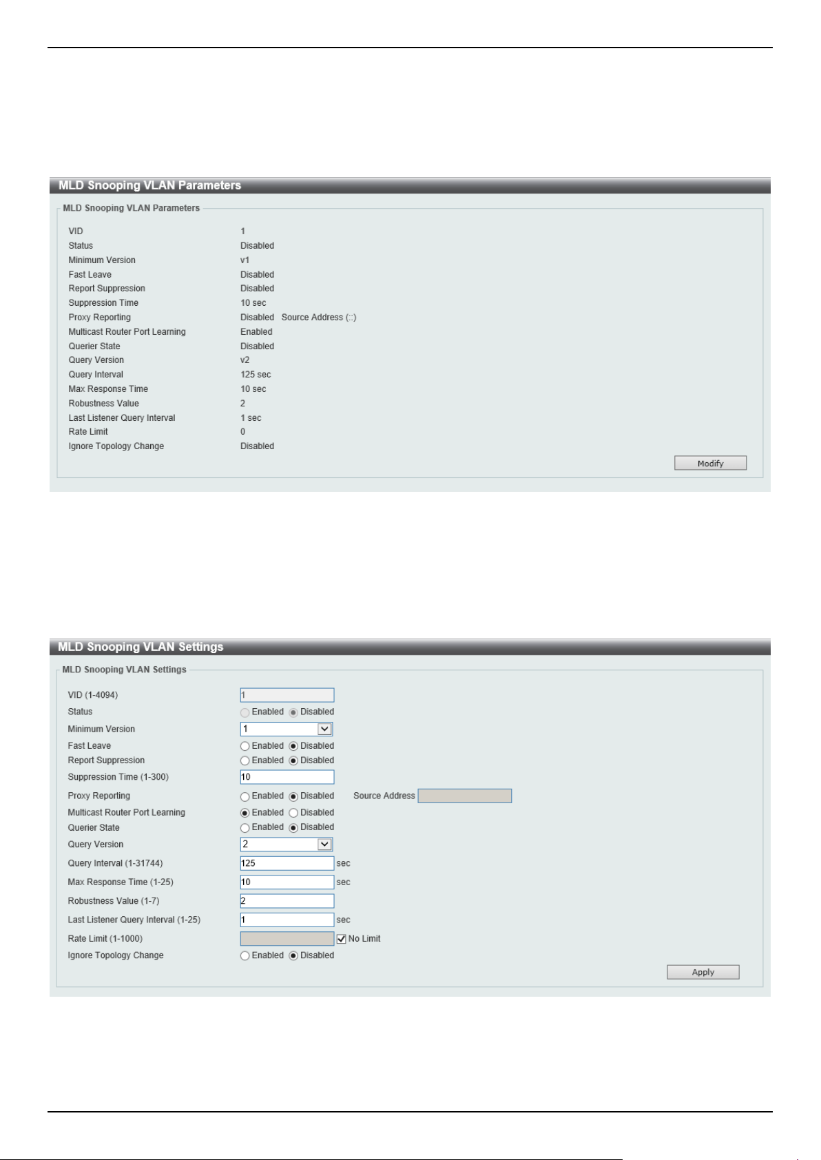
DGS-1520 Series Gigabit Ethernet Smart Managed Switch Web UI Reference Guide
190
Click the Show Detail button to see the detail information of the specific VLAN.
Click the Edit button to re-configure the specific entry.
Enter a page number and click the Go button to navigate to a specific page when multiple pages exist.
After clicking the Show Detail button, the following window will appear.
Figure 5-83 MLD Snooping Settings (Show Detail) Window
The window displays the detail information about MLD snooping VLAN.
Click the Modify button to edit the information in the following window.
After clicking the Modify or Edit button in MLD Snooping Settings window, the following window will appear.
Figure 5-84 MLD Snooping Settings (Modify, Edit) Window

DGS-1520 Series Gigabit Ethernet Smart Managed Switch Web UI Reference Guide
191
The fields that can be configured are described below:
Parameter Description
Minimum Version
Select the minimum version of MLD hosts that is allowed on the VLAN. Options to
choose from are 1 and 2.
Fast Leave
Select this option to enable or disable the MLD snooping Fast Leave function. If
enabled, the membership is immediately removed when the system receives the
MLD done message from the last member.
Report Suppression
Select this option to enable or disable the report suppression.
Suppression Time
Enter the interval of suppressing duplicate MLD reports or leaves. The range is
from 1 to 300.
Proxy Reporting
Select this option to enable or disable the proxy-reporting function.
Source Address
Enter the source IP of proxy reporting.
This is available when Enabled is selected in Proxy Reporting.
Multicast Router Port
Learning
Select this option to enable or disable Multicast Router port learning.
Querier State
Select this option to enable or disable the querier state.
Query Version
Select the general query packet version sent by the MLD snooping querier.
Options to choose from are 1 and 2.
Query Interval
Enter the interval at which the MLD snooping querier sends MLD general query
messages periodically. The range is from 1 to 31744.
Max Response Time
Enter the maximum response time, in seconds, advertised in MLD snooping
queries. The range is from 1 to 25.
Robustness Value
Enter the robustness variable used in MLD snooping. The range is from 1 to 7.
Last Listener Query Interval
Enter the interval at which the MLD snooping querier sends MLD group-specific or
group-source-specific (channel) query messages. The range is from 1 to 25.
Rate Limit
Enter the rate limit value here. The range is from 1 to 1000.
Tick the No Limit option to apply no rate limit on this profile.
Ignore Topology Change
Select to enable or disable the Ignore Topology Change feature here.
Click the Apply button to accept the changes made.
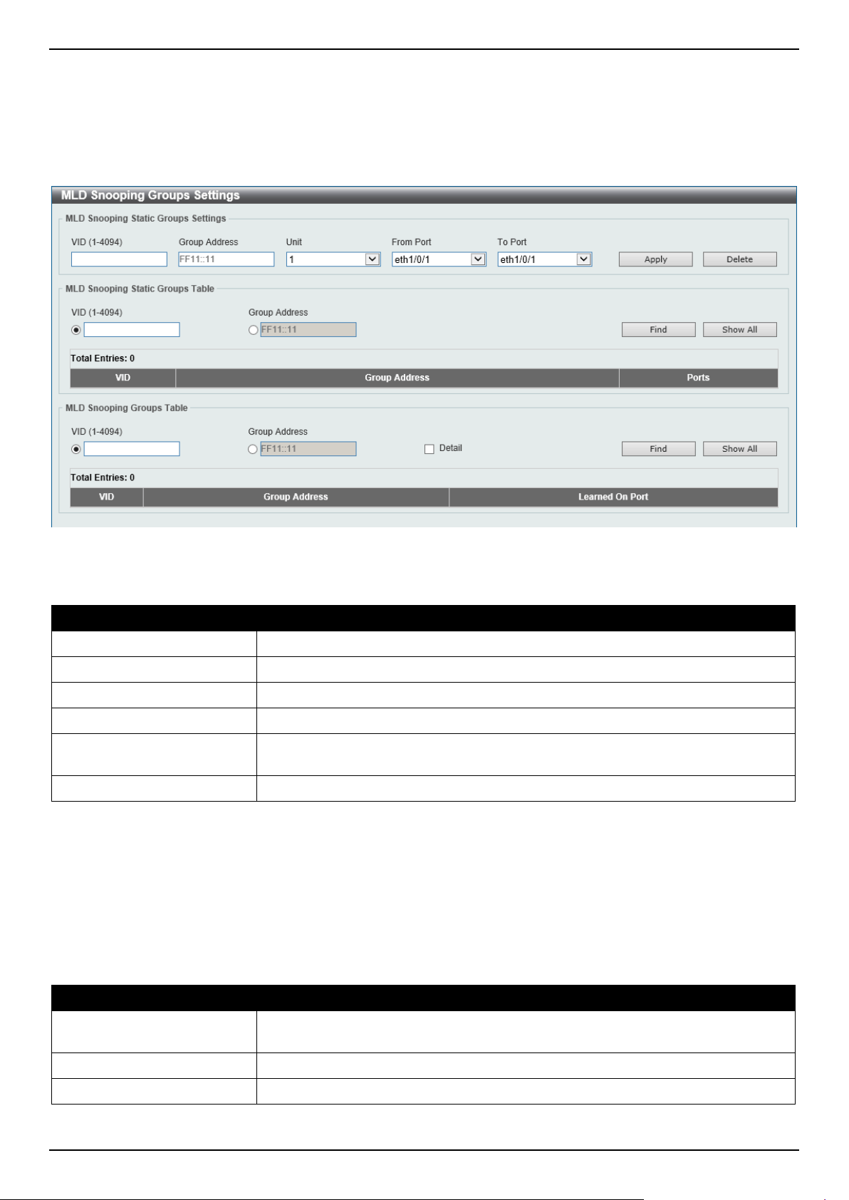
DGS-1520 Series Gigabit Ethernet Smart Managed Switch Web UI Reference Guide
192
MLD Snooping Groups Settings
This window is used to display and configure the MLD snooping static group, and view MLD snooping group.
To view the following window, click L2 Features > L2 Multicast Control > MLD Snooping > MLD Snooping Groups
Settings, as shown below:
Figure 5-85 MLD Snooping Groups Settings Window
The fields that can be configured in MLD Snooping Static Groups Settings/Table are described below:
Parameter Description
VID
Enter the VLAN ID of the multicast group here. The range is from 1 to 4094.
Group Address
Enter the IPv6 multicast group address here.
Unit
Select the Switch unit that will be used for this configuration here.
From Port - To Port
Select the appropriate port range used for the configuration here.
VID
Click the radio button and enter a VLAN ID of the multicast group. The range is
from 1 to 4094.
Group Address
Click the radio button and enter an IPv6 multicast group address.
Click the Apply button to accept the changes made.
Click the Delete button to remove the specified entry.
Click the Find button to locate a specific entry based on the information entered.
Click the Show All button to view all the entries.
Enter a page number and click the Go button to navigate to a specific page when multiple pages exist.
The fields that can be configured in MLD Snooping Groups Table are described below:
Parameter Description
VID
Click the radio button and enter a VLAN ID of the multicast group. The range is
from 1 to 4094.
Group Address
Click the radio button and enter an IPv6 multicast group address.
Detail
Select this option to display the MLD group detail information.
Click the Find button to locate a specific entry based on the information entered.
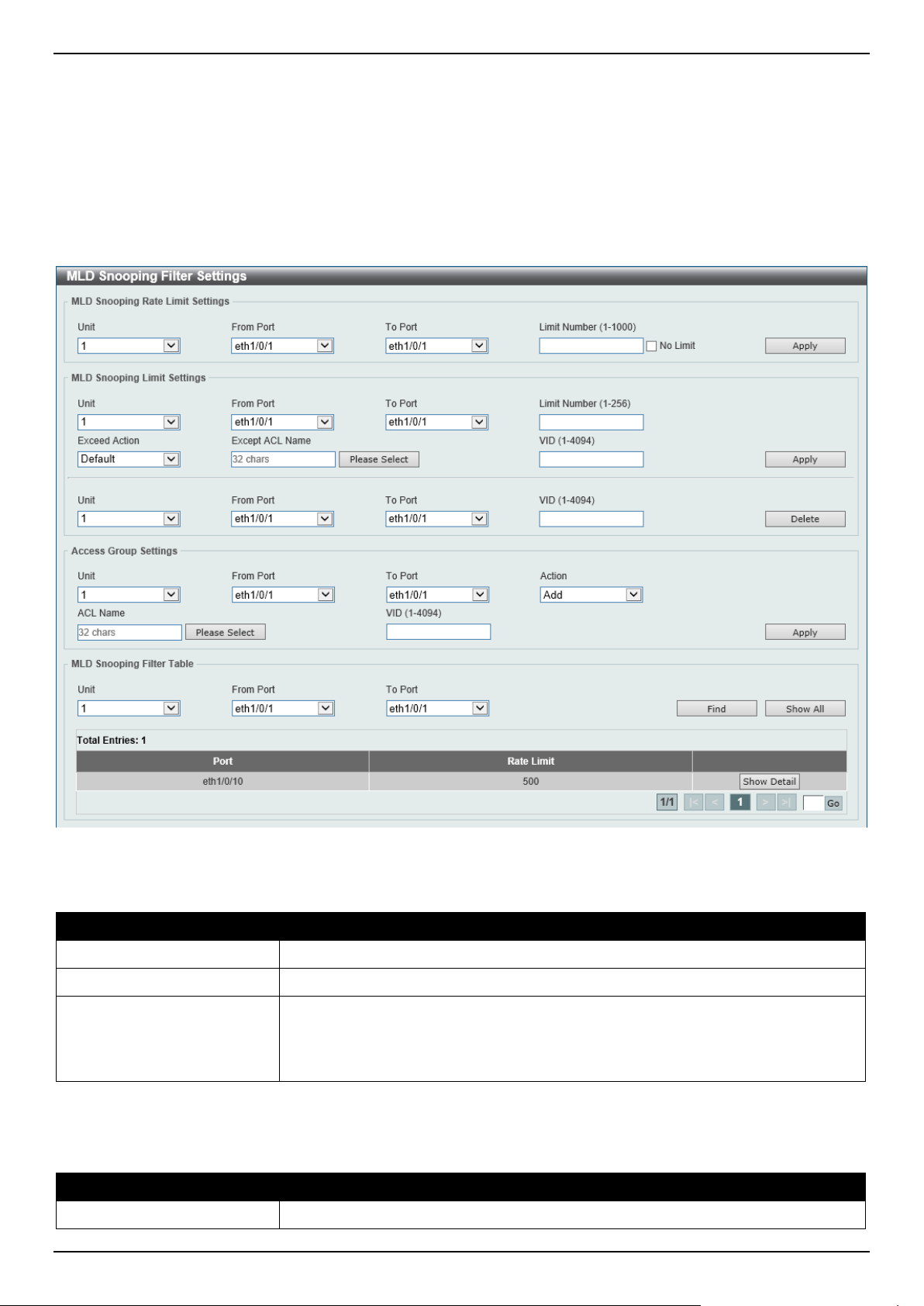
DGS-1520 Series Gigabit Ethernet Smart Managed Switch Web UI Reference Guide
193
Click the Show All button to view all the entries.
MLD Snooping Filter Settings
This window is used to display and configure the MLD snooping settings.
To view the following window, click L2 Features > L2 Multicast Control > MLD Snooping > MLD Snooping Filter
Settings, as shown below:
Figure 5-86 MLD Snooping Filter Settings Window
The fields that can be configured in MLD Snooping Rate Limit Settings are described below:
Parameter Description
Unit
Select the Switch unit ID that will be used here.
From Port - To Port
Select the Switch port range that will be used here.
Limit Number
Enter the limit number here. This is to configure the rate of MLD control packets
that the Switch can process on a specific interface. The range is from 1 to 1000
packets per second.
Select the No Limit option to remove the limitation.
Click the Apply button to accept the changes made.
The fields that can be configured in MLD Snooping Limit Settings are described below:
Parameter Description
Unit
Select the Switch unit that will be used for this configuration here.

DGS-1520 Series Gigabit Ethernet Smart Managed Switch Web UI Reference Guide
194
Parameter Description
From Port - To Port
Select the appropriate port range used for the configuration here.
Limit Number
Enter the limit number here. This is used to set the limitation on the number of
MLD cache entries that can be created. The range is from 1 to 256.
Exceed Action
Select the exceed action here. This parameter specifies the action for handling
newly learned groups when the limitation is exceeded.
Options to choose from are:
• Default - Specifies that the default action will be taken.
• Drop - Specifies that the new group will be dropped.
• Replace - Specifies that the new group will replace the oldest group.
Except ACL Name
Enter the standard IP access list name here. The group (*,G) permitted by the
access list will be excluded from the limit. To permit a group (*,G), specify "any" in
the source address field and G in the destination address field of the access list
entry. This name can be up to 32 characters long.
Alternatively, click the Please Select button to find and select any of the exiting
access lists configured on this Switch to be used in this configuration.
VID
Enter the Layer 2 VLAN name on a trunk port here. This applies the filter to
packets that arrive on that VLAN. The range is from 1 to 4094.
Click the Apply button to accept the changes made.
Click the Delete button to delete an entry based on the information entered.
The fields that can be configured in Access Group Settings are described below:
Parameter Description
Unit
Select the Switch unit that will be used for this configuration here.
From Port - To Port
Select the appropriate port range used for the configuration here.
Action Select Add to add a new entry based in the information entered.
Select Delete to delete an entry based in the information entered.
ACL Name
Enter the standard IP access list name here. This is used to permit users to join a
group (*, G), specify "any" in source address field and G in destination address
field of the access list entry. This name can be up to 32 characters long.
Alternatively, click the Please Select button to find and select any of the exiting
access lists configured on this Switch to be used in this configuration.
VID
Enter the VLAN ID used for this configuration here. The range is from 1 to 4094.
Click the Apply button to accept the changes made.
The fields that can be configured in MLD Snooping Filter Table are described below:
Parameter Description
Unit
Select the Switch unit ID that will be used here.
From Port - To Port
Select the Switch port range that will be used here.
Click the Find button to locate a specific entry based on the information entered.
Click the Show All button to display all the entries.
Click the Show Detail button to view detailed information about the entry.
Enter a page number and click the Go button to navigate to a specific page when multiple pages exist.
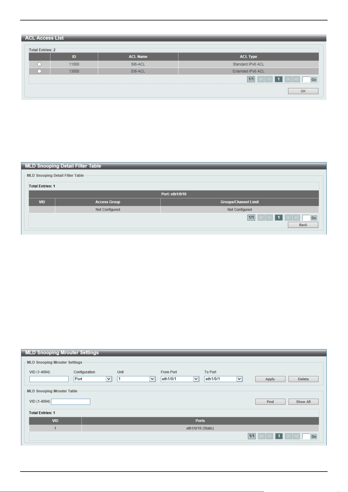
DGS-1520 Series Gigabit Ethernet Smart Managed Switch Web UI Reference Guide
195
After clicking the Please Select button, the following page will appear.
Figure 5-87 MLD Snooping Filter Settings (Please Select) Window
Select the ACL and click the OK button to use the selected access list.
Enter a page number and click the Go button to navigate to a specific page when multiple pages exist.
After clicking the Show Detail button, the following window will appear.
Figure 5-88 MLD Snooping Filter Settings (Show Detail) Window
Click the Back button to return to the previous window.
Enter a page number and click the Go button to navigate to a specific page when multiple pages exist.
MLD Snooping Mrouter Settings
This window is used to display and configure the specified interface(s) as the router ports or forbidden to be IPv6
multicast router ports on the VLAN interface on the Switch.
To view the following window, click L2 Features > L2 Multicast Control > MLD Snooping > MLD Snooping
Mrouter Settings, as shown below:
Figure 5-89 MLD Snooping Mrouter Settings Window
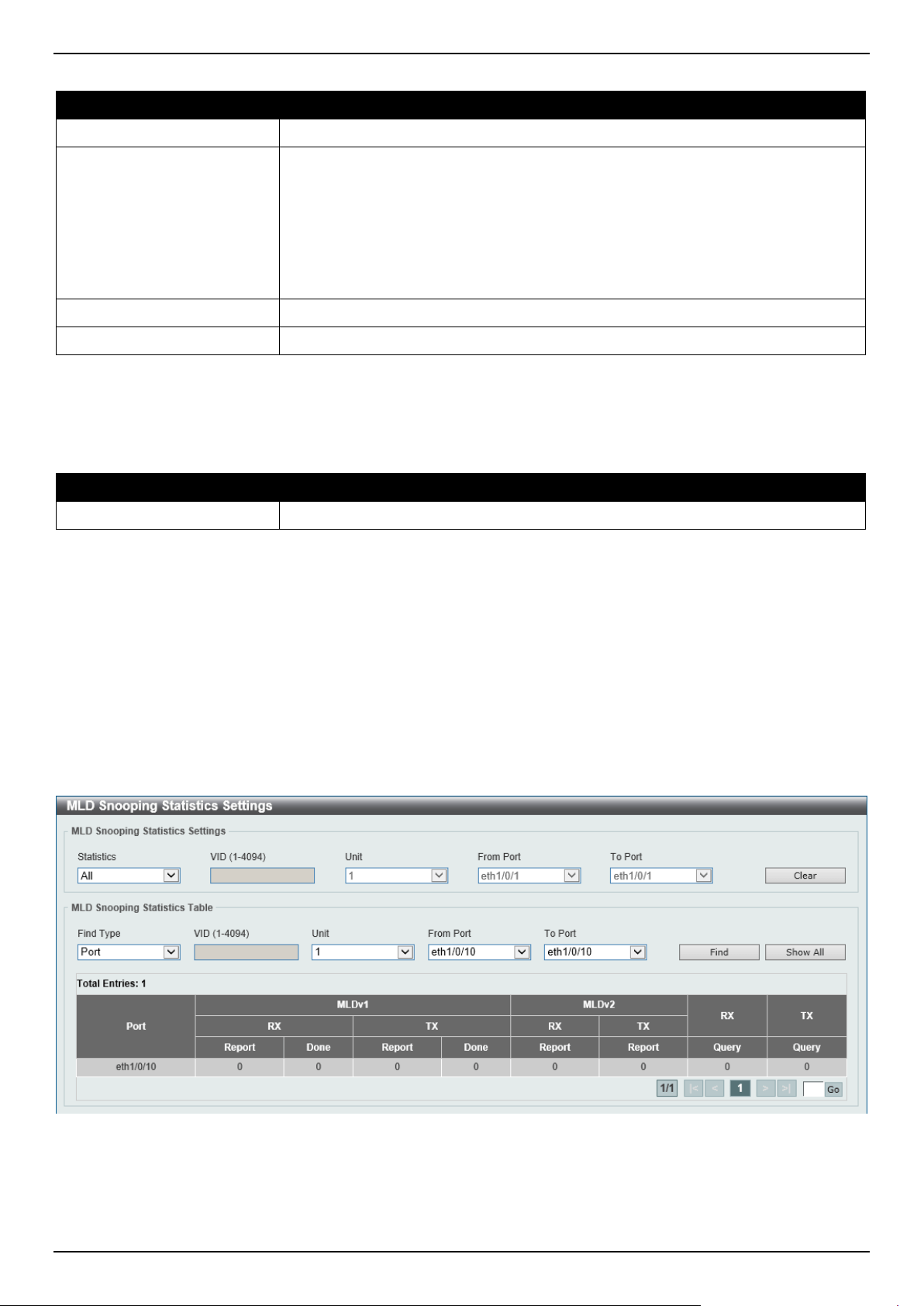
DGS-1520 Series Gigabit Ethernet Smart Managed Switch Web UI Reference Guide
196
The fields that can be configured in MLD Snooping Mrouter Settings are described below:
Parameter Description
VID
Enter a VLAN ID between 1 and 4094.
Configuration
Select the port configuration. Options to choose from are:
• Port - Select to have the configured ports as being connected to multicast-
enabled routers.
• Forbidden Port - Select to have the configured ports as being not
connected to multicast-enabled routers.
• Multicast Router Port Learning - Select to enable dynamic learning of
multicast router port.
Unit
Select the Switch unit that will be used for this configuration here.
From Port - To Port
Select the appropriate port range used for the configuration here.
Click the Apply button to accept the changes made.
Click the Delete button to remove the specified entry.
The fields that can be configured in MLD Snooping Mrouter Table are described below:
Parameter Description
VID
Enter a VLAN ID between 1 and 4094.
Click the Find button to locate a specific entry based on the information entered.
Click the Show All button to view all the entries.
Enter a page number and click the Go button to navigate to a specific page when multiple pages exist.
MLD Snooping Statistics Settings
This window is used to view and clear the MLD snooping related statistics.
To view the following window, click L2 Features > L2 Multicast Control > MLD Snooping > MLD Snooping
Statistics Settings, as shown below:
Figure 5-90 MLD Snooping Statistics Settings Window

DGS-1520 Series Gigabit Ethernet Smart Managed Switch Web UI Reference Guide
197
The fields that can be configured in MLD Snooping Statistics Settings are described below:
Parameter Description
Statistics Select the interface here. Options to choose from are All, VLAN, and Port.
VID
Enter a VLAN ID between 1 and 4094.
This is available when VLAN is selected in the Statistics drop-down list.
Unit
Select the Switch unit that will be used for this configuration here.
This is available when Port is selected in the Statistics drop-down list.
From Port - To Port
Select the appropriate port range used for the configuration here.
This is available when Port is selected in the Statistics drop-down list.
Click the Clear button to clear the MLD snooping related statistics.
The fields that can be configured in MLD Snooping Statistics Table are described below:
Parameter Description
Find Type Select the interface type. Options to choose from are VLAN, and Port.
VID
Enter a VLAN ID between 1 and 4094.
This is available when VLAN is selected in the Find Type drop-down list.
Unit
Select the Switch unit that will be used for this configuration here.
This is available when Port is selected in the Find Type drop-down list.
From Port - To Port
Select the appropriate port range used for the configuration here.
This is available when Port is selected in the Find Type drop-down list.
Click the Find button to locate a specific entry based on the information entered.
Click the Show All button to view all the entries.
Enter a page number and click the Go button to navigate to a specific page when multiple pages exist.
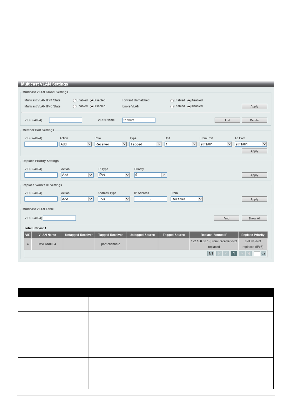
DGS-1520 Series Gigabit Ethernet Smart Managed Switch Web UI Reference Guide
198
Multicast VLAN
Multicast VLAN Settings
This window is used to display and configure the multicast VLAN settings.
To view the following window, click L2 Features > L2 Multicast Control > Multicast VLAN > Multicast VLAN
Settings, as shown below:
Figure 5-91 Multicast VLAN Settings Window
The fields that can be configured in Multicast VLAN Global Settings are described below:
Parameter Description
Multicast VLAN IPv4 State
Select to enable or disable the IPv4 IGMP control packet process in multicast
VLANs.
Forward Unmatched
Select the enable or disable the Forward Unmatched feature here. This specifies
that if the received IGMP or MLD control packet is untagged, does not match any
profile, and the associated default VLAN is a multicast VLAN, or is tagged with a
multicast VLAN, but does not match the associated profile, then the packet will be
forwarded or dropped based on this setting. By default, the packet will be dropped.
Multicast VLAN IPv6 State
Select to enable or disable the IPv6 MLD control packet process in multicast
VLANs.
Ignore VLAN
Select the enable or disable the ignore VLAN feature here. This specifies the
setting for tagged IGMP or MLD control packets. If enabled, then the packet's
VLAN is ignored and taken to match the profile to find its multicast VLAN. When
this option is enabled, the Switch will ignore the VLAN of the receiving IGMP or
MLD control packet and try to find a match profile.

DGS-1520 Series Gigabit Ethernet Smart Managed Switch Web UI Reference Guide
199
Parameter Description
VID
Enter the VLAN ID of the multicast VLAN that will be created or deleted here. The
range is 2 to 4094.
VLAN Name
Enter the VLAN name of the multicast VLAN that will be created or deleted here.
Click the Apply button to accept the changes made.
Click the Delete button to delete an entry based on the information entered.
Click the Add button to add a new entry based on the information entered.
The fields that can be configured in Member Port Settings are described below:
Parameter Description
VID
Enter the multicast VLAN ID that will be used here. The range is 2 to 4094.
Action Select Add to add a new entry based in the information entered.
Select Delete to delete an entry based in the information entered.
Role
Select the role here. Options to choose from are:
• Receiver - Specifies to configure the port as a subscriber port that can only
receive multicast data in the multicast VLAN.
• Source - Specifies to configure the port as an uplink port that can send
multicast data in the multicast VLAN.
Type
Select the type here. Options to choose from are:
• Tagged - Specifies that if a port is a tagged member, the packets sent from
the port are tagged with the Multicast VLAN ID.
• Untagged - Specifies that if the port is an untagged member, then the
packets will be forwarded in the untagged form.
Unit
Select the Switch unit ID that will be used here.
From Port - To Port
Select the Switch port range that will be used here.
Click the Apply button to accept the changes made.
The fields that can be configured in Replace Priority Settings are described below:
Parameter Description
VID
Enter the multicast VLAN ID that will be used here. The range is 2 to 4094.
Action Select Add to add a new entry based in the information entered.
Select Delete to delete an entry based in the information entered.
IP Type
Select the IP type here. Options to choose from are:
• IPv4 - Specifies to the remap priority for IPv4 multicast packets forwarded
on the multicast VLAN.
• IPv6 - Specifies to the remap priority for IPv6 multicast packets forwarded
on the multicast VLAN.
Priority
Select the priority value here. The range is from 0 to 7.
Click the Apply button to accept the changes made.
The fields that can be configured in Replace Source IP Settings are described below:
Parameter Description
VID
Enter the multicast VLAN ID that will be used here. The range is 2 to 4094.
Action Select Add to add a new entry based in the information entered.
Select Delete to delete an entry based in the information entered.

DGS-1520 Series Gigabit Ethernet Smart Managed Switch Web UI Reference Guide
200
Parameter Description
Address Type
Select the address type here. Options to choose from are:
• IPv4 - Specifies to enter the source IPv4 address for IGMP control packet
reporting up to routers.
• IPv6 - Specifies to enter the source IPv6 address for MLD control packet
reporting up to routers.
IP Address
Enter the IPv4/IPv6 address here.
From
Select the "from" option here. Options to choose from are:
• Receiver - Specifies that the source IPv4/IPv6 address of the IGMP/MLD
report/leave packet received on any multicast VLAN receiver port will be
replaced.
• Source - Specifies that the source IPv4/IPv6 address of the IGMP/MLD
report/leave packet received on any multicast VLAN source port will be
replaced.
• Both - Specifies that the source IPv4/IPv6 address of the IGMP/MLD
report/leave packet received on any port in the multicast VLAN will be
replaced.
Click the Apply button to accept the changes made.
The fields that can be configured in Multicast VLAN Table are described below:
Parameter Description
VID
Enter the multicast VLAN ID that will be used here. The range is 2 to 4094.
Click the Find button to locate a specific entry based on the information entered.
Click the Show All button to view all the entries.
Enter a page number and click the Go button to navigate to a specific page when multiple pages exist.
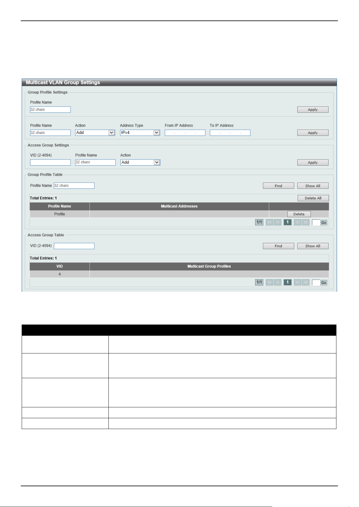
DGS-1520 Series Gigabit Ethernet Smart Managed Switch Web UI Reference Guide
201
Multicast VLAN Group Settings
This window is used to view and configure the multicast VLAN group settings.
To view the following window, click L2 Features > L2 Multicast Control > Multicast VLAN > Multicast VLAN Group
Settings, as shown below:
Figure 5-92 Multicast VLAN Group Settings Window
The fields that can be configured in Group Profile Settings are described below:
Parameter Description
Profile Name
Enter the group profile name for the multicast VLAN feature here. This name can
be up to 32 characters long.
Action Select the action that will be taken here. Options to choose from are Add and
Delete. Multiple ranges can be added to a multicast VLAN profile. The IP address
ranges, specified in a single profile, must be of the same address family.
Address Type
Select the address type here. Options to choose from are:
• IPv4 - Specifies to use IPv4 multicast addresses in the range.
• IPv6 - Specifies to use IPv6 multicast addresses in the range.
From IP Address
Enter the source IPv4/IPv6 address here.
To IP Address
Enter the destination IPv4/IPv6 address here.
Click the Apply button to accept the changes made.

DGS-1520 Series Gigabit Ethernet Smart Managed Switch Web UI Reference Guide
202
The fields that can be configured in Access Group Settings are described below:
Parameter Description
VID
Enter the multicast VLAN ID that will be used here. The range is 2 to 4094.
Profile Name
Enter the group profile name for the multicast VLAN feature here. This name can
be up to 32 characters long.
Action Select the action that will be taken here. Options to choose from are Add and
Delete. This is to add or delete the multicast group entirely.
Click the Apply button to accept the changes made.
The fields that can be configured in Group Profile Table are described below:
Parameter Description
Profile Name
Enter the group profile name for the multicast VLAN feature here. This name can
be up to 32 characters long.
Click the Find button to locate a specific entry based on the information entered.
Click the Show All button to display all the entries.
Click the Delete All button to delete all the entries found in the display table.
Click the Delete button to delete the specified entry.
Enter a page number and click the Go button to navigate to a specific page when multiple pages exist.
The fields that can be configured in Access Group Table are described below:
Parameter Description
VID
Enter the multicast VLAN ID that will be used here. The range is 2 to 4094.
Click the Find button to locate a specific entry based on the information entered.
Click the Show All button to display all the entries.
Enter a page number and click the Go button to navigate to a specific page when multiple pages exist.
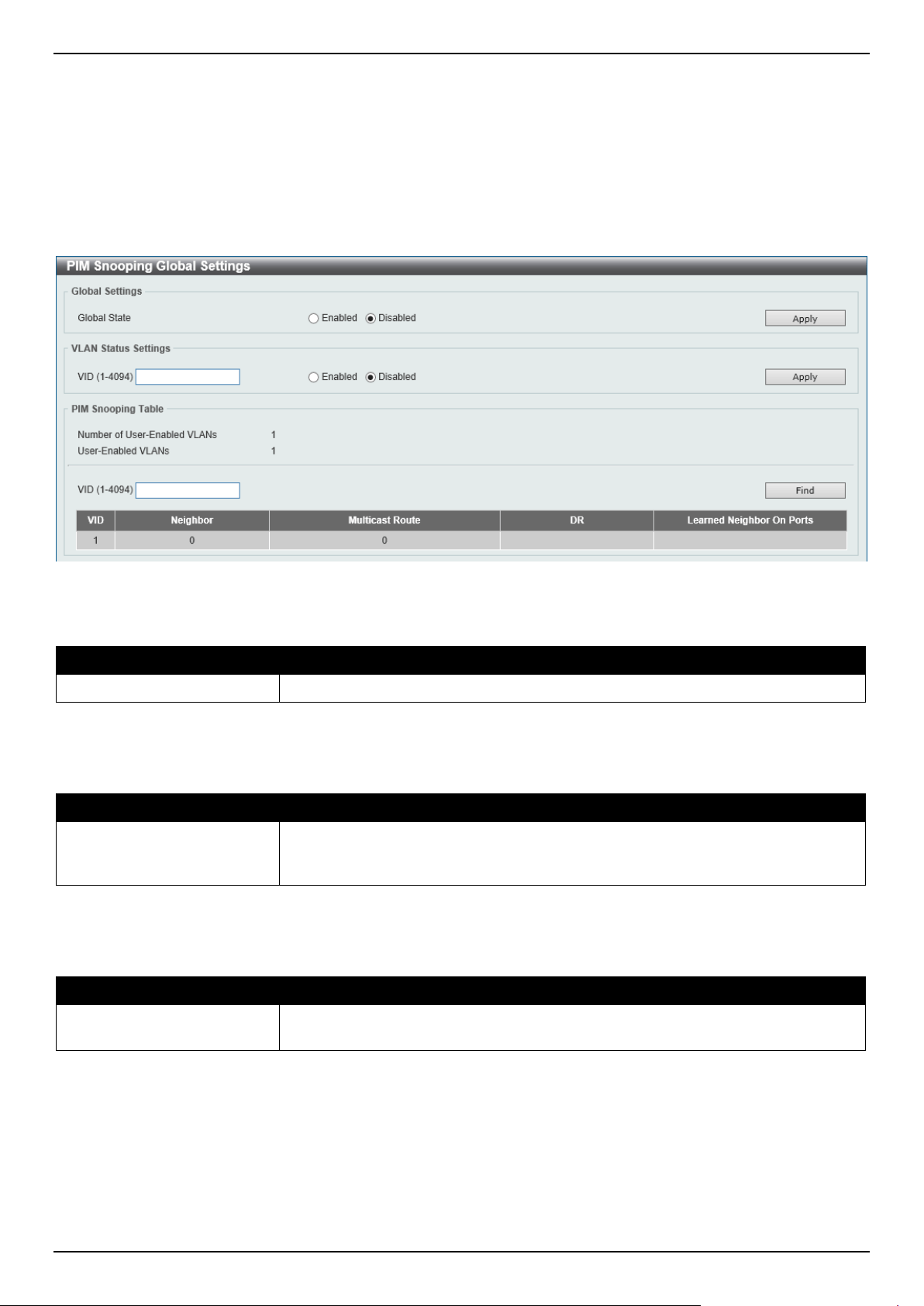
DGS-1520 Series Gigabit Ethernet Smart Managed Switch Web UI Reference Guide
203
PIM Snooping
PIM Snooping Global Settings
This window is used to display and configure the global Protocol Independent Multicast (PIM) snooping settings.
To view the following window, click L2 Features > L2 Multicast Control > PIM Snooping > PIM Snooping Global
Settings, as shown below:
Figure 5-93 PIM Snooping Global Settings Window
The fields that can be configured in Global Settings are described below:
Parameter Description
Global State
Select to globally enable or disable the PIM snooping feature here.
Click the Apply button to accept the changes made.
The fields that can be configured in VLAN Status Settings are described below:
Parameter Description
VID
Enter the VLAN ID on which the PIM snooping feature will be used here. The
range is from 1 to 4094. Select to enable or disable the PIM snooping feature on
the specified VLAN here.
Click the Apply button to accept the changes made.
The fields that can be configured in PIM Snooping Table are described below:
Parameter Description
VID
Enter the VLAN ID that will be used in the display here. The range is from 1 to
4094.
Click the Find button to generate the display based on the information entered.
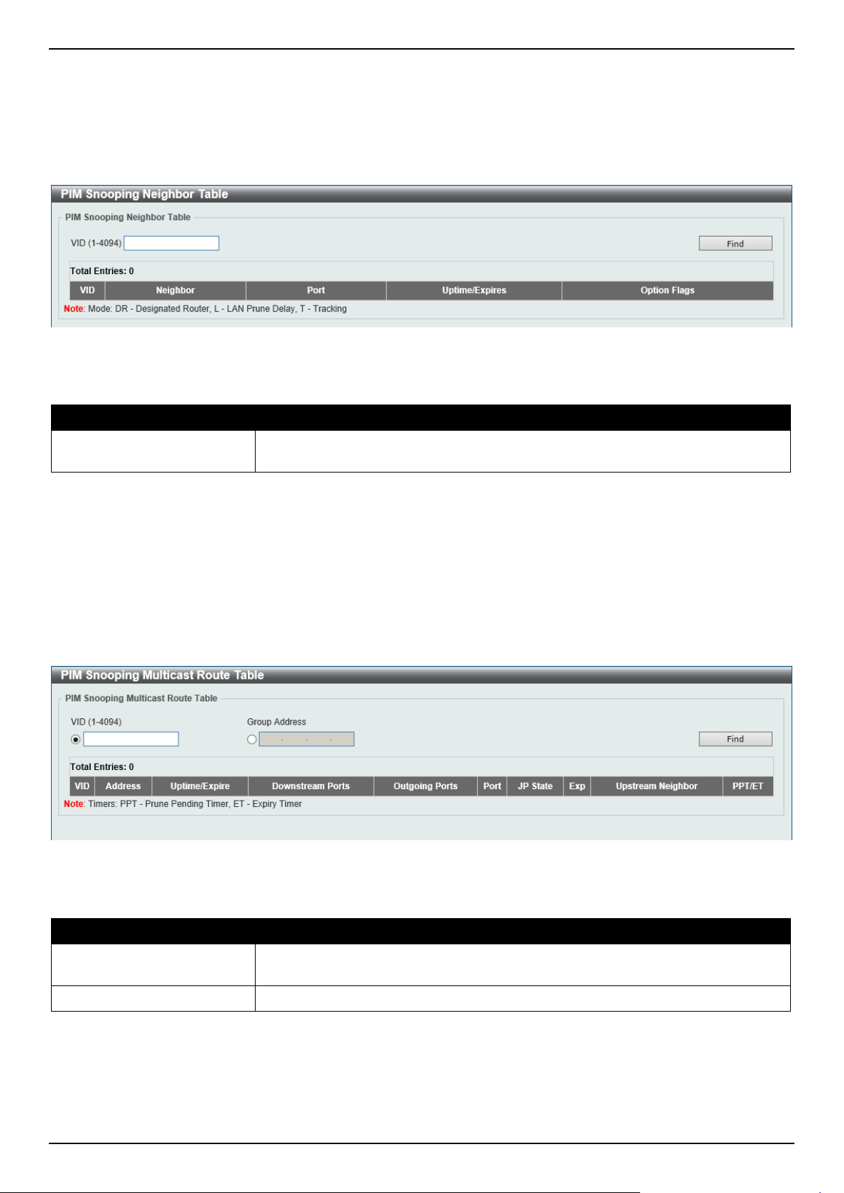
DGS-1520 Series Gigabit Ethernet Smart Managed Switch Web UI Reference Guide
204
PIM Snooping Neighbor Table
This window is used to view the PIM snooping neighbor table.
To view the following window, click L2 Features > L2 Multicast Control > PIM Snooping > PIM Snooping Neighbor
Table, as shown below:
Figure 5-94 PIM Snooping Neighbor Table Window
The fields that can be configured are described below:
Parameter Description
VID
Enter the VLAN ID that will be used in this display here. The range is from 1 to
4094.
Click the Find button to generate the display based on the information entered.
PIM Snooping Multicast Route Table
This window is used to view the PIM snooping multicast route table.
To view the following window, click L2 Features > L2 Multicast Control > PIM Snooping > PIM Snooping Multicast
Route Table, as shown below:
Figure 5-95 PIM Snooping Multicast Route Table Window
The fields that can be configured are described below:
Parameter Description
VID
Select and enter the VLAN ID that will be used in this display here. The range is
from 1 to 4094.
Group Address
Select and enter the group address here.
Click the Find button to generate the display based on the information entered.
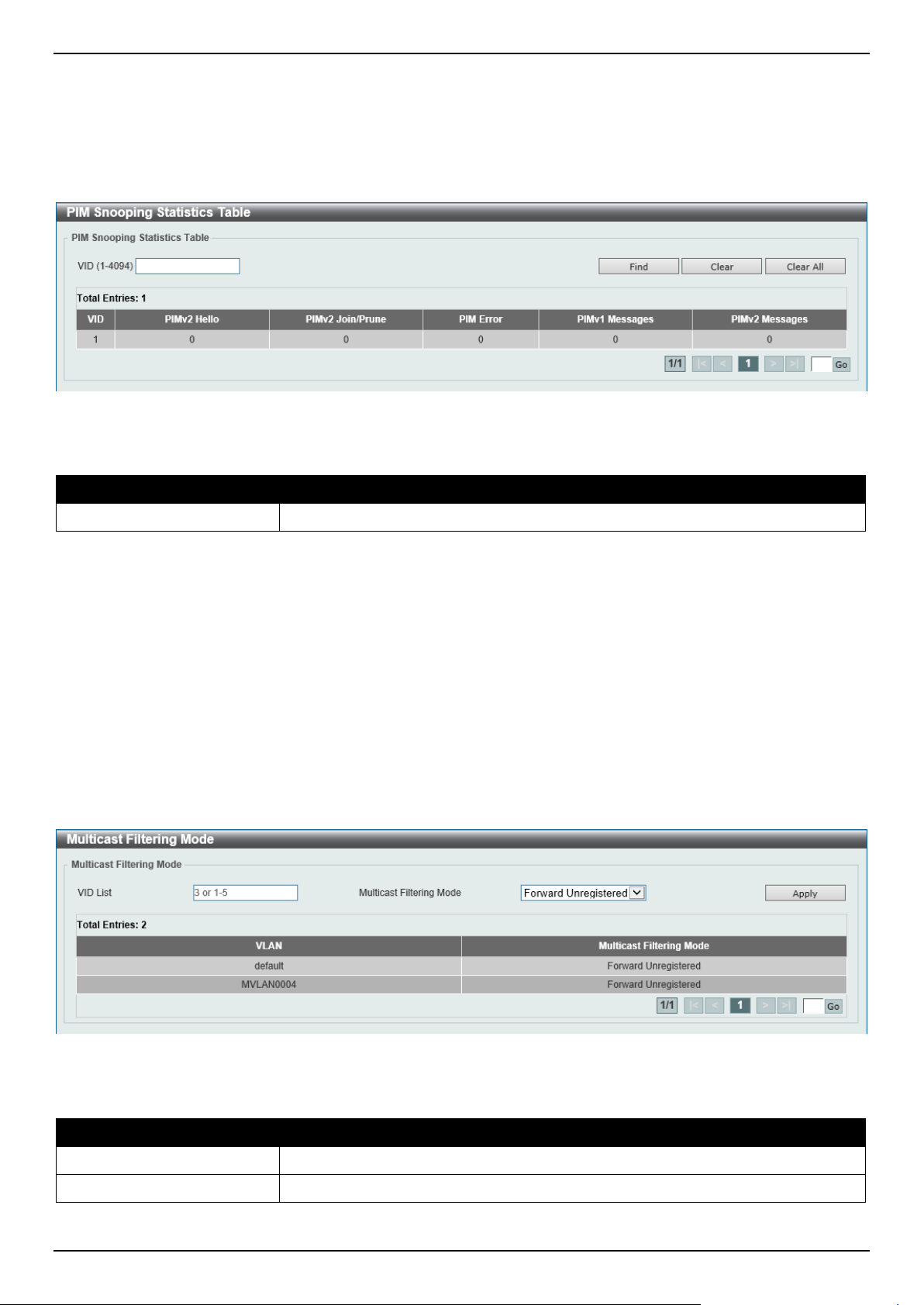
DGS-1520 Series Gigabit Ethernet Smart Managed Switch Web UI Reference Guide
205
PIM Snooping Statistics Table
This window is used to view and clear the PIM snooping statistics table.
To view the following window, click L2 Features > L2 Multicast Control > PIM Snooping > PIM Snooping
Statistics Table, as shown below:
Figure 5-96 PIM Snooping Statistics Table Window
The fields that can be configured are described below:
Parameter Description
VID
Select and enter the VLAN ID that will be used here. The range is from 1 to 4094.
Click the Find button to generate the display based on the information entered.
Click the Clear button to clear the statistics information related to the specified VLAN.
Click the Clear All button to clear all the statistics information displayed in the table.
Enter a page number and click the Go button to navigate to a specific page when multiple pages exist.
Multicast Filtering Mode
This window is used to display and configure the Layer 2 multicast filtering settings.
To view the following window, click L2 Features > L2 Multicast Control > Multicast Filtering Mode, as shown
below:
Figure 5-97 Multicast Filtering Mode Window
The fields that can be configured are described below:
Parameter Description
VID List
Enter the VLAN ID list that will be used for this configuration here.
Multicast Filtering Mode
Select the multicast filtering mode here. Options to choose from are:
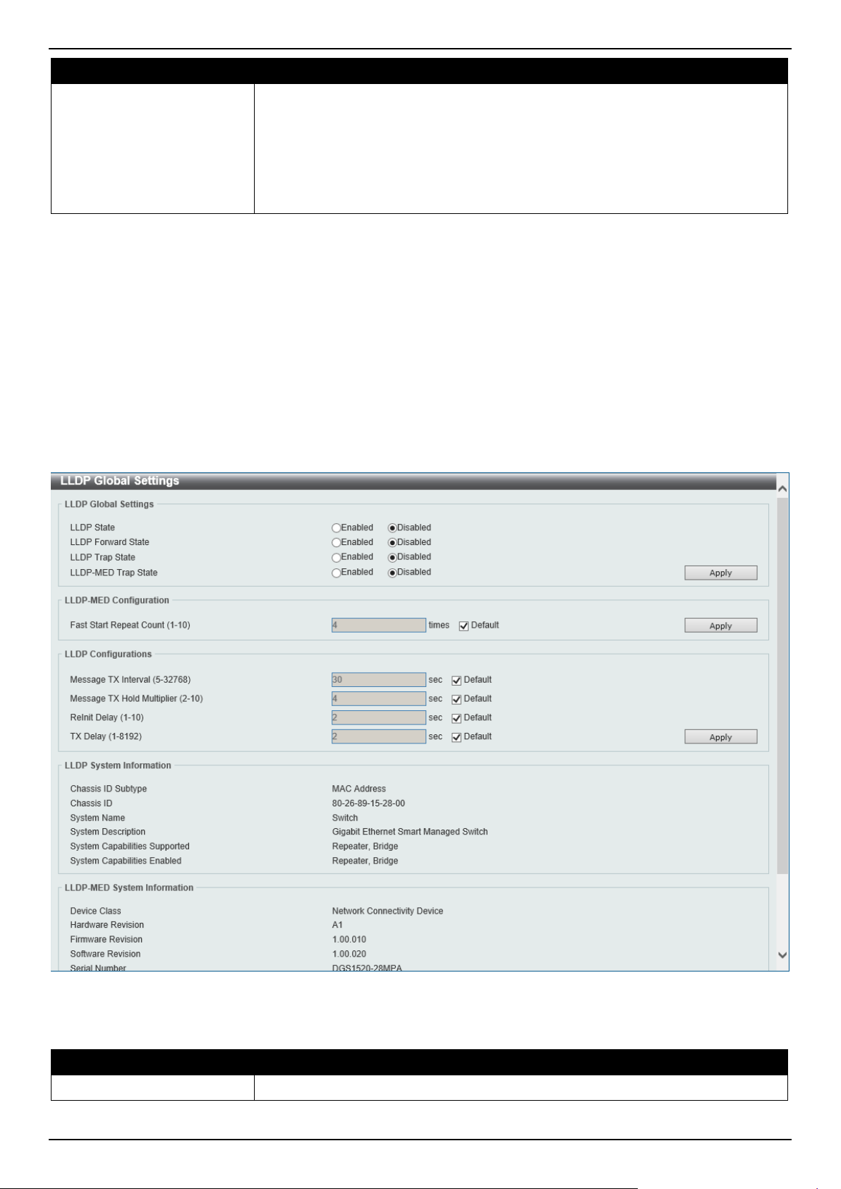
DGS-1520 Series Gigabit Ethernet Smart Managed Switch Web UI Reference Guide
206
Parameter Description
• Forward Unregistered - Registered multicast packets will be forwarded
based on the forwarding table and all unregistered multicast packets will be
flooded based on the VLAN domain.
• Forward All - All multicast packets will be flooded based on the VLAN
domain.
• Filter Unregistered - Registered packets will be forwarded based on the
forwarding table and all unregistered multicast packets will be filtered.
Click the Apply button to accept the changes made.
Enter a page number and click the Go button to navigate to a specific page when multiple pages exist.
LLDP
LLDP Global Settings
This window is used to display and configure the global LLDP settings.
To view the following window, click L2 Features > LLDP > LLDP Global Settings, as shown below:
Figure 5-98 LLDP Global Settings Window
The fields that can be configured in LLDP Global Settings are described below:
Parameter Description
LLDP State
Select this option to enable or disable the LLDP feature
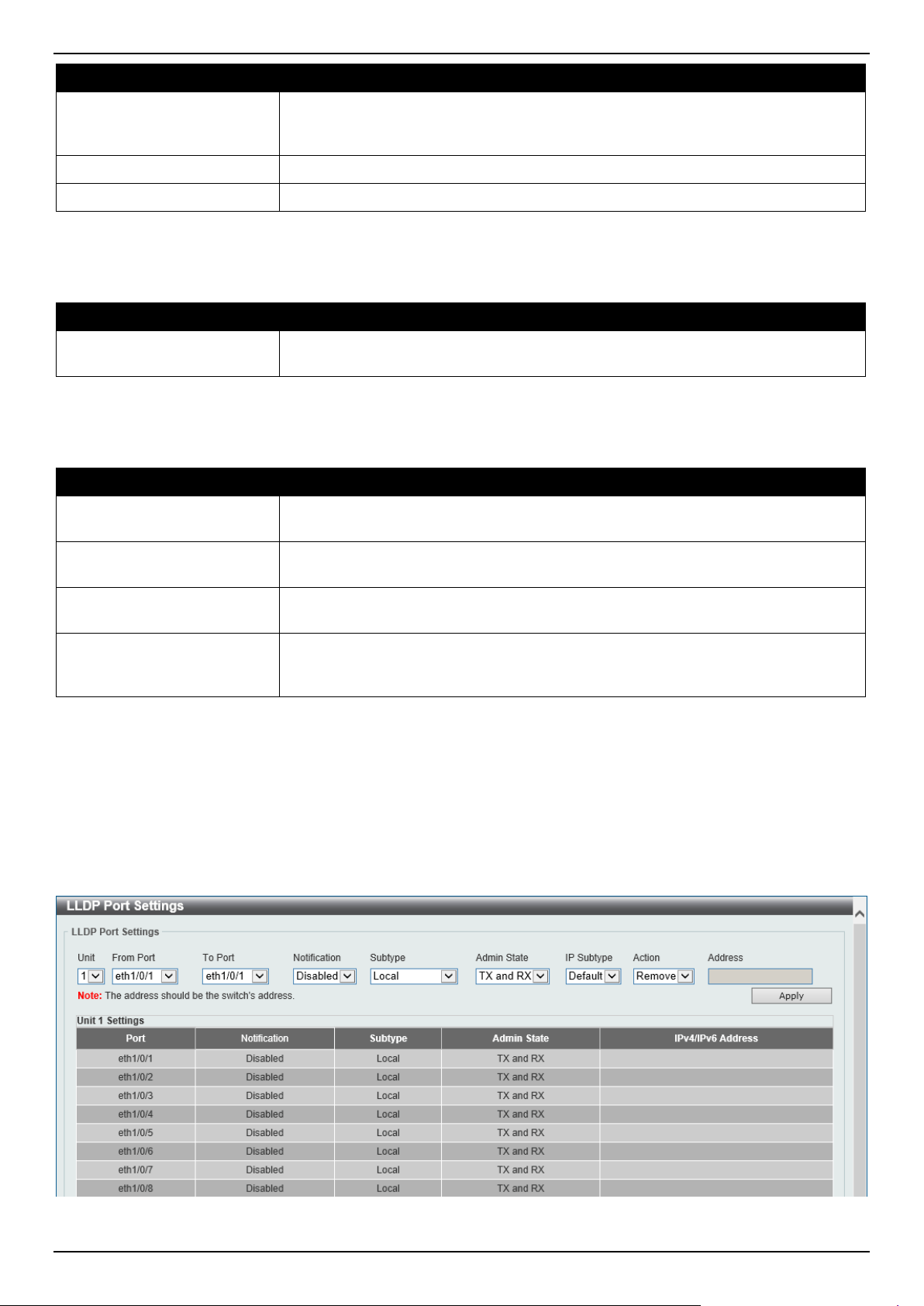
DGS-1520 Series Gigabit Ethernet Smart Managed Switch Web UI Reference Guide
207
Parameter Description
LLDP Forward State Select this option to enable or disable LLDP forward state. When the LLDP State
is disabled and LLDP Forward Sate is enabled, the received LLDPDU packet will
be forwarded.
LLDP Trap State
Select this option to enable or disable the LLDP trap state.
LLDP-MED Trap State
Select this option to enable or disable the LLDP-MED trap state.
Click the Apply button to accept the changes made.
The fields that can be configured in LLDP-MED Settings are described below:
Parameter Description
Fast Start Repeat Count
Enter the LLDP-MED fast start repeat count value. This value must be between 1
and 10.
Click the Apply button to accept the changes made.
The fields that can be configured in LLDP Configurations are described below:
Parameter Description
Message TX Interval
Enter the interval between consecutive transmissions of LLDP advertisements on
each physical interface. The range is from 5 to 32768 seconds.
Message TX Hold Multiplier
Enter the multiplier on the LLDPDUs transmission interval that used to calculate
the TTL value of an LLDPDU. This value must be between 2 and 10.
ReInit Delay
Enter the delay value for LLDP initialization on an interface. This value must be
between 1 and 10 seconds.
TX Delay
Enter the delay value for sending successive LLDPDUs on an interface. The valid
values are from 1 to 8192 seconds and should not be greater than one-fourth of
the transmission interval timer.
Click the Apply button to accept the changes made.
LLDP Port Settings
This window is used to display and configure the LLDP port settings.
To view the following window, click L2 Features > LLDP > LLDP Port Settings, as shown below:
Figure 5-99 LLDP Port Settings Window
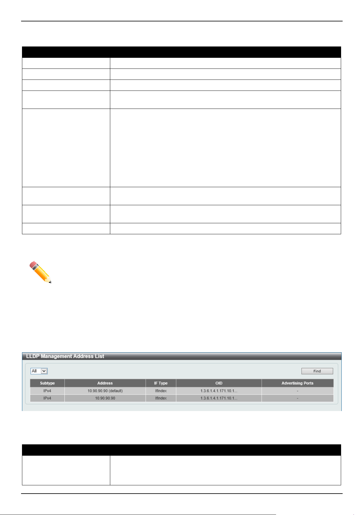
DGS-1520 Series Gigabit Ethernet Smart Managed Switch Web UI Reference Guide
208
The fields that can be configured are described below:
Parameter Description
Unit
Select the Switch unit that will be used for this configuration here.
From Port - To Port
Select the appropriate port range used for the configuration here.
Notification
Select to enable or disable the notification feature here.
Subtype Select the subtype of LLDP TLV(s). Options to choose from are MAC Address,
and Local.
Admin State
Select the local LLDP agent and allow it to send and receive LLDP frames on the
port. Options to choose from are:
• TX - The local LLDP agent can only transmit LLDP frames.
• RX - The local LLDP agent can only receive LLDP frames.
• TX and RX - The local LLDP agent can both transmit and receive LLDP
frames.
• Disabled - The local LLDP agent can neither transmit nor receive LLDP
frames.
By default, the TX and RX option is used.
IP Subtype
Select the type of the IP address information to be sent. Options to choose from
are Default, IPv4, and IPv6.
Action Select the action that will be taken here. Options to choose from are Remove and
Add.
Address
Enter the IP address that will be sent.
Click the Apply button to accept the changes made.
NOTE: The IPv4 or IPv6 address entered here should be an existing LLDP management IP address.
LLDP Management Address List
This window is used to view the LLDP management address list.
To view the following window, click L2 Features > LLDP > LLDP Management Address List, as shown below:
Figure 5-100 LLDP Management Address List Window
The fields that can be configured are described below:
Parameter Description
Subtype
Select the subtype. Options to choose from are:
• All - Specifies to display all entries.
• IPv4 - Enter the IPv4 address in the space provided.
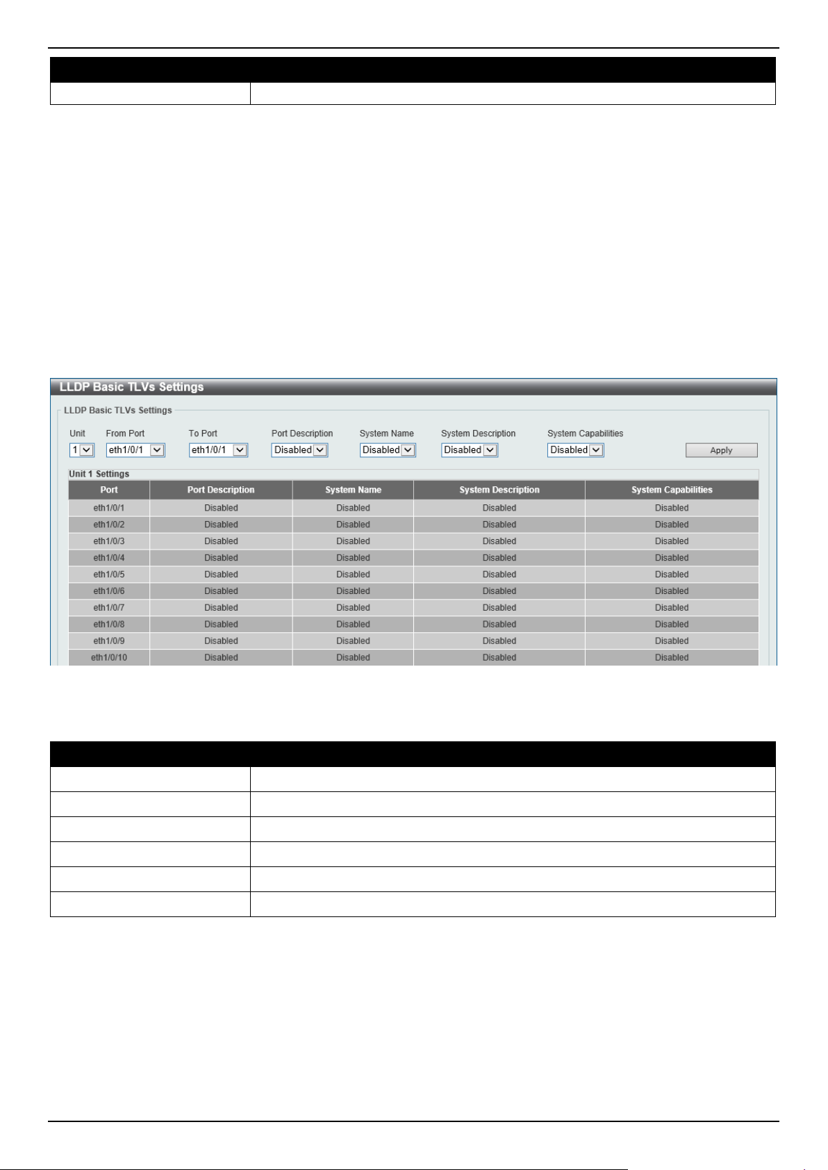
DGS-1520 Series Gigabit Ethernet Smart Managed Switch Web UI Reference Guide
209
Parameter Description
• IPv6 - Enter the IPv6 address in the space provided.
Click the Find button to locate a specific entry based on the selection made.
LLDP Basic TLVs Settings
The Type-Length-Value (TLV) field allows specific information to be sent within LLDP packets. This window is used to
configure basic TLV settings. An active LLDP port on the Switch always includes mandatory data in its outbound
advertisements. There are four optional data types that can be configured to exclude one or more of these data types
from outbound LLDP advertisements. The mandatory data type includes four basic types of TLVs: end of LLDPDU
TLV, chassis ID TLV, port ID TLV, and TTL TLV. The mandatory data types cannot be disabled. There are also four
data types, which can be optionally selected. These include Port Description, System Name, System Description, and
System Capability.
To view the following window, click L2 Features > LLDP > LLDP Basic TLVs Settings, as shown below:
Figure 5-101 LLDP Basic TLVs Settings Window
The fields that can be configured are described below:
Parameter Description
Unit
Select the Switch unit that will be used for this configuration here.
From Port - To Port
Select the appropriate port range used for the configuration here.
Port Description
Select this option to enable or disable the Port Description option.
System Name
Select this option to enable or disable the System Name option.
System Description
Select this option to enable or disable the System Description option.
System Capabilities
Select this option to enable or disable the System Capabilities option.
Click the Apply button to accept the changes made.
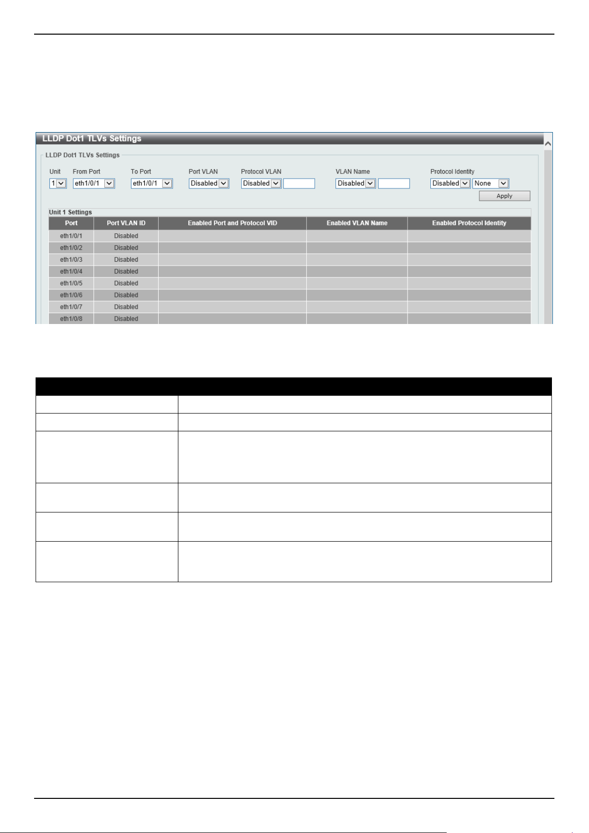
DGS-1520 Series Gigabit Ethernet Smart Managed Switch Web UI Reference Guide
210
LLDP Dot1 TLVs Settings
The LLDP Dot1 TLVs Settings page is used to enable or disable outbound LLDP advertisements for IEEE 802.1
organizationally unique port VLAN ID TLVs.
To view the following window, click L2 Features > LLDP > LLDP Dot1 TLVs Settings, as shown below:
Figure 5-102 LLDP Dot1 TLVs Settings Window
The fields that can be configured are described below:
Parameter Description
Unit
Select the Switch unit that will be used for this configuration here.
From Port - To Port
Select the appropriate port range used for the configuration here.
Port VLAN
Select this option to enable or disable sending the port VLAN ID TLV. The Port
VLAN ID TLV is an optional fixed length TLV that allows a VLAN bridge port to
advertise the port VLAN ID (PVID) that will be associated with untagged or priority
tagged frames.
Protocol VLAN
Select this option to enable or disable sending the Port and Protocol VLAN ID
(PPVID) TLV. Enter the VLAN ID in PPVID TLV.
VLAN Name
Select this option to enable or disable sending the VLAN name TLV. Enter the ID
of the VLAN in the VLAN name TLV.
Protocol Identity
Select this option to enable or disable sending the Protocol Identity TLV and the
protocol name. Options for protocol name to choose from are None, EAPOL,
LACP, GVRP, STP, and All.
Click the Apply button to accept the changes made.
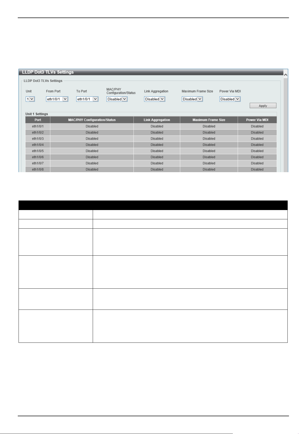
DGS-1520 Series Gigabit Ethernet Smart Managed Switch Web UI Reference Guide
211
LLDP Dot3 TLVs Settings
The LLDP Dot3 TLVs Settings page is used to enable or disable outbound LLDP advertisements for IEEE 802.3
organizationally unique TLVs.
To view the following window, click L2 Features > LLDP > LLDP Dot3 TLVs Settings, as shown below:
Figure 5-103 LLDP Dot3 TLVs Settings Window
The fields that can be configured are described below:
Parameter Description
Unit
Select the Switch unit that will be used for this configuration here.
From Port - To Port
Select the appropriate port range used for the configuration here.
MAC/PHY
Configuration/Status
Select this option to enable or disable the MAC/PHY Configuration/Status TLV to
send. The MAC/PHY Configuration/Status TLV is an optional TLV that identifies (1)
the duplex and bit-rate capability of the sending IEEE 802.3 LAN node, and (2) the
current duplex and bit-rate settings of the sending IEEE 802.3 LAN node.
Link Aggregation
Select this option to enable or disable the Link Aggregation TLV to send. The Link
Aggregation TLV indicates contains the following information. Whether the link is
capable of being aggregated, whether the link is currently in an aggregation, and
the aggregated port channel ID of the port. If the port is not aggregated, then the
ID is 0.
Maximum Frame Size
Select this option to enable or disable the Maximum Frame Size TLV to send. The
Maximum Frame Size TLV indicates the maximum frame size capability of the
implemented MAC and PHY.
Power Via MDI
Select this option to enable or disable the power via MDI TLV to send. IEEE 802.3
PMD implementations allow power to be supplied over the link for connected non-
powered systems. The Power Via MDI TLV allows network management to
advertise and discover the MDI power support capabilities of the sending IEEE
802.3 LAN station.
Click the Apply button to accept the changes made.
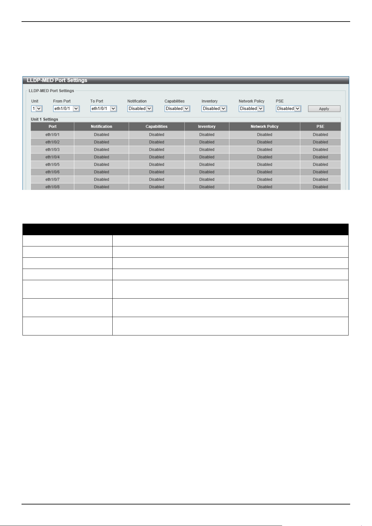
DGS-1520 Series Gigabit Ethernet Smart Managed Switch Web UI Reference Guide
212
LLDP-MED Port Settings
The LLDP-MED Port Settings page is used to enable or disable outbound LLDP advertisements for LLDP-MED TLVs.
To view the following window, click L2 Features > LLDP > LLDP-MED Port Settings, as shown below:
Figure 5-104 LLDP-MED Port Settings Window
The fields that can be configured are described below:
Parameter Description
Unit
Select the Switch unit that will be used for this configuration here.
From Port - To Port
Select the appropriate port range used for the configuration here.
Notification
Select this option to enable or disable transmitting the LLDP-MED notification TLV.
Capabilities
Select this option to enable or disable transmitting the LLDP-MED capabilities TLV.
Inventory
Select this option to enable or disable transmitting the LLDP-MED inventory
management TLV.
Network Policy
Select this option to enable or disable transmitting the LLDP-MED network policy
TLV.
PSE
Select this option to enable or disable transmitting the LLDP-MED extended power
via MDI TLV, if the local device is PSE device or PD device.
Click the Apply button to accept the changes made.
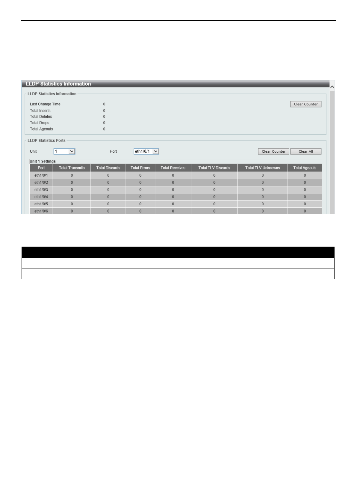
DGS-1520 Series Gigabit Ethernet Smart Managed Switch Web UI Reference Guide
213
LLDP Statistics Information
This window is used to view the neighbor detection activity, LLDP Statistics, and the settings for individual ports on the
Switch.
To view the following window, click L2 Features > LLDP > LLDP Statistics Information, as shown below:
Figure 5-105 LLDP Statistics Information Window
The fields that can be configured are described below:
Parameter Description
Unit
Select the Switch unit that will be used here.
Port
Select the port number that will be used here.
Click the Clear Counter button to clear the counter information for the statistics displayed.
Click the Clear All button to clear all the counter information displayed.
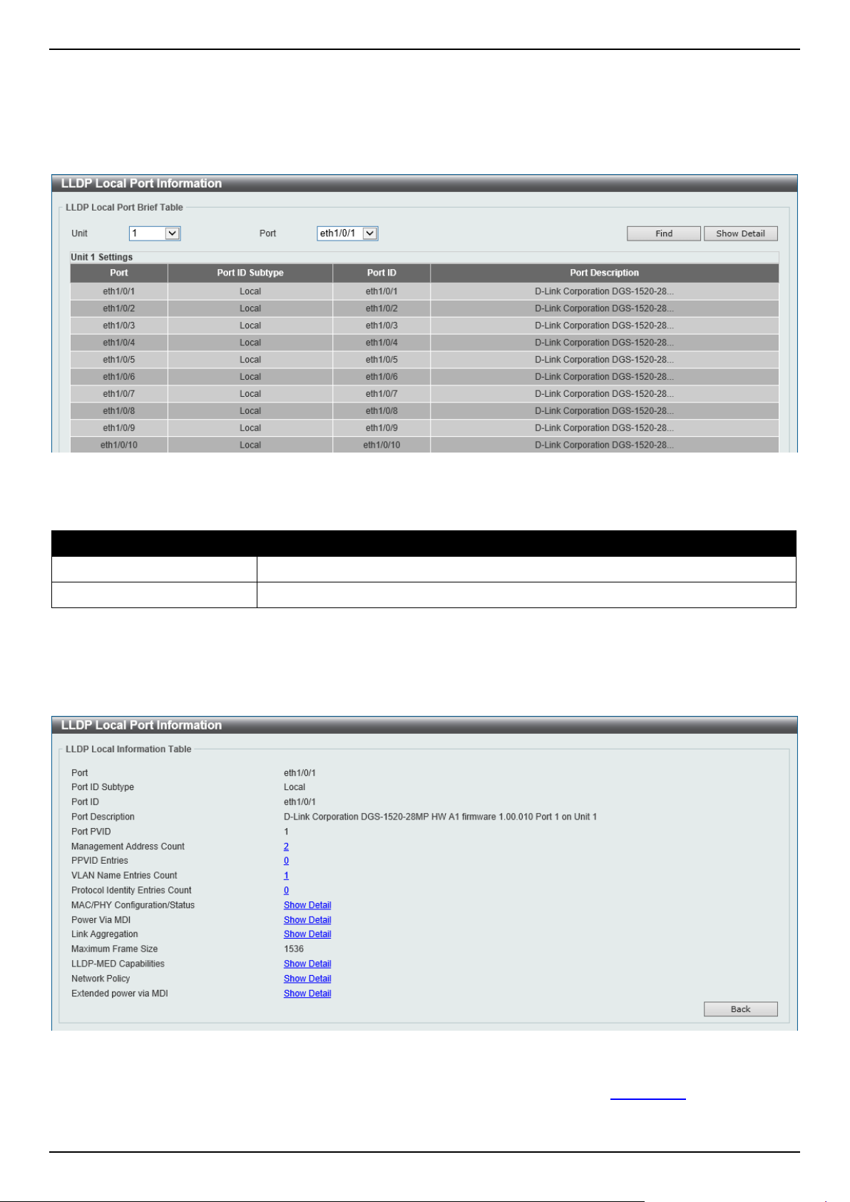
DGS-1520 Series Gigabit Ethernet Smart Managed Switch Web UI Reference Guide
214
LLDP Local Port Information
This window is used to display the information currently available for populating outbound LLDP advertisements.
To view the following window, click L2 Features > LLDP > LLDP Local Port Information, as shown below:
Figure 5-106 LLDP Local Port Information Window
The fields that can be configured are described below:
Parameter Description
Unit
Select the Switch unit that will be displayed.
Port
Select the port number that will be displayed.
Click the Find button to locate a specific entry based on the information entered.
Click the Show Detail button to view detailed information of the specific port.
After clicking the Show Detail button, the following window will appear.
Figure 5-107 LLDP Local Port Information (Show Detail) Window
To view more details about, for example, the MAC/PHY Configuration/Status, click the Show Detail hyperlink.
Click the Back button to return to the previous window.
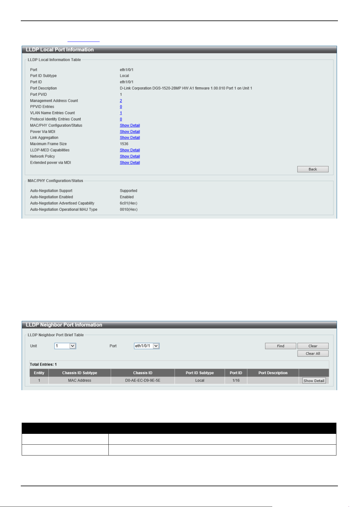
DGS-1520 Series Gigabit Ethernet Smart Managed Switch Web UI Reference Guide
215
After clicking the Show Detail hyperlink, a new section will appear at the bottom of the window.
Figure 5-108 LLDP Local Port Information (Show Detail) Window
Click the Back button to return to the previous window.
LLDP Neighbor Port Information
This window is used to display the LLDP information learned from neighboring switches. The Switch receives packets
from a remote station but is able to store the information locally.
To view the following window, click L2 Features > LLDP > LLDP Neighbor Port Information, as shown below:
Figure 5-109 LLDP Neighbor Port Information Window
The fields that can be configured are described below:
Parameter Description
Unit
Select the Switch unit that will be displayed.
Port
Select the port number that will be displayed.
Click the Find button to locate a specific entry based on the information entered.
Click the Clear button to clear the specific port information.
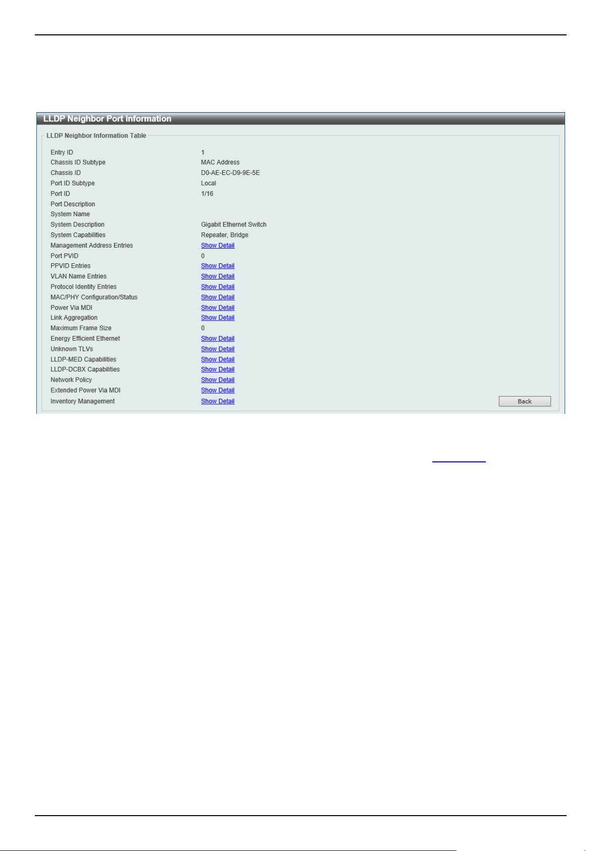
DGS-1520 Series Gigabit Ethernet Smart Managed Switch Web UI Reference Guide
216
Click the Clear All button to clear all the port information displayed.
Click the Show Detail button to view detailed information of the specific port.
After clicking the Show Detail button, the following window will appear.
Figure 5-110 LLDP Neighbor Port Information (Show Detail) Window
To view more details about, for example, the MAC/PHY Configuration/Status, click the Show Detail hyperlink.
Click the Back button to return to the previous window.
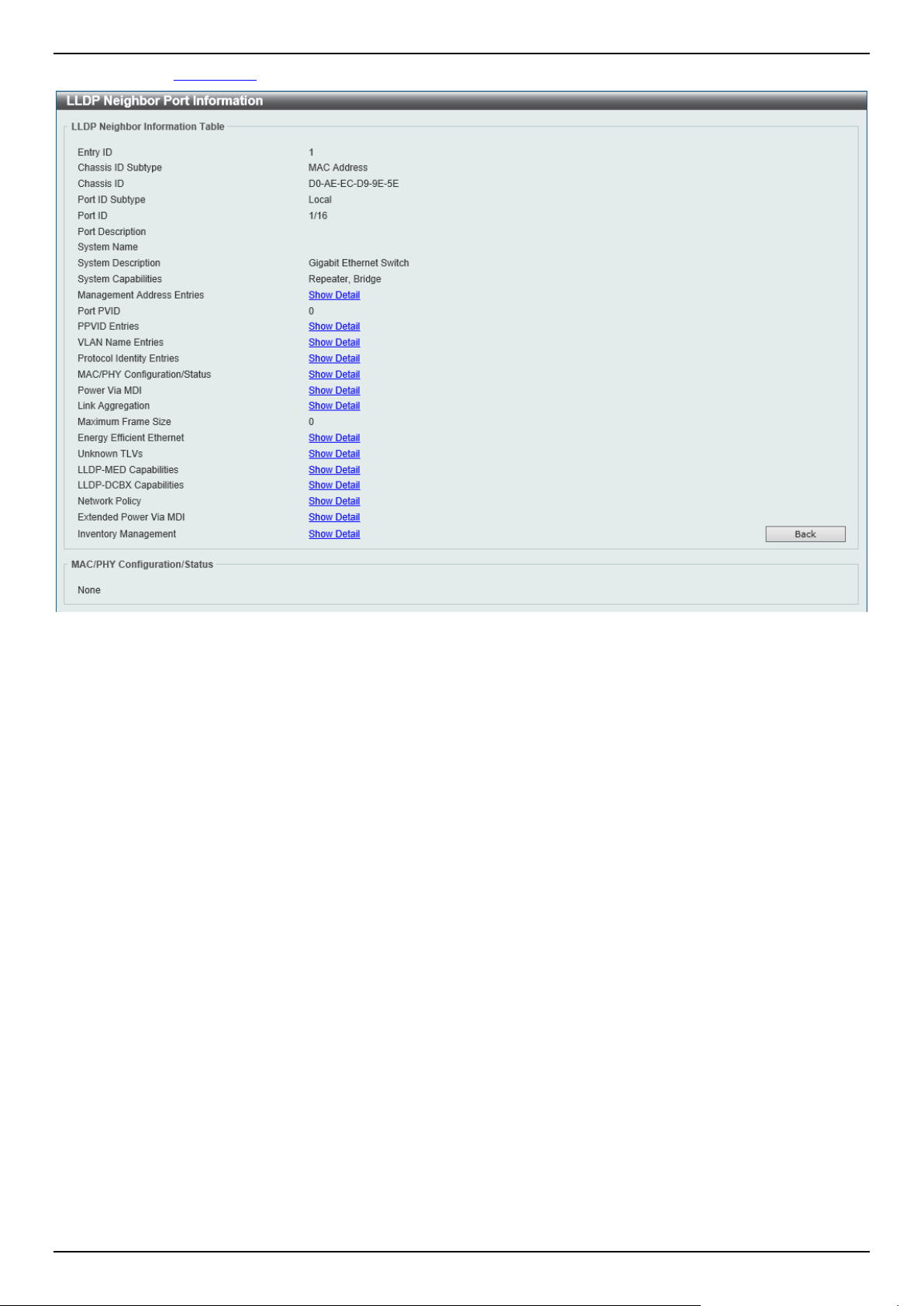
DGS-1520 Series Gigabit Ethernet Smart Managed Switch Web UI Reference Guide
217
After clicking the Show Detail hyperlink, a new section will appear at the bottom of the window.
Figure 5-111 LLDP Neighbor Port Information (Show Detail) Window
Click the Back button to return to the previous window.
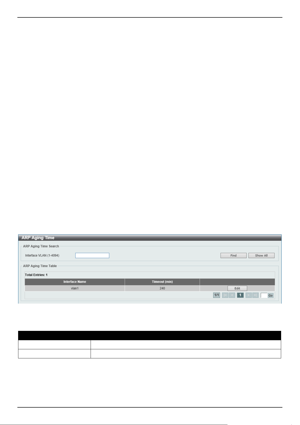
DGS-1520 Series Gigabit Ethernet Smart Managed Switch Web UI Reference Guide
218
6. Layer 3 Features
ARP
Gratuitous ARP
IPv6 Neighbor
Interface
UDP Helper
IPv4 Static/Default Route
IPv4 Route Table
IPv6 Static/Default Route
IPv6 Route Table
Route Preference
ECMP Settings
IPv6 General Prefix
URPF Settings
RIP
RIPng
OSPF
IP Multicast Routing Protocol
IP Route Filter
Policy Route
VRRP Settings
VRRPv3 Settings
ARP
ARP Aging Time
This window is used to display and configure the ARP aging time settings.
To view the following window, click L3 Features > ARP > ARP Aging Time, as shown below:
Figure 6-1 ARP Aging Time Window
The fields that can be configured are described below:
Parameter Description
Interface VLAN
Enter the interface VLAN ID here. The range is from 1 to 4094.
Timeout After click the Edit button, enter the ARP aging timeout value here.
Click the Find button to find and display the entries, based on the information entered, in the ARP Aging Time Table.
Click the Show All button to display all the static ARP aging time entries in the ARP Aging Time Table.
Click the Edit button to re-configure the specific entry.
Click the Apply button to accept the changes made.
Enter a page number and click the Go button to navigate to a specific page when multiple pages exist.
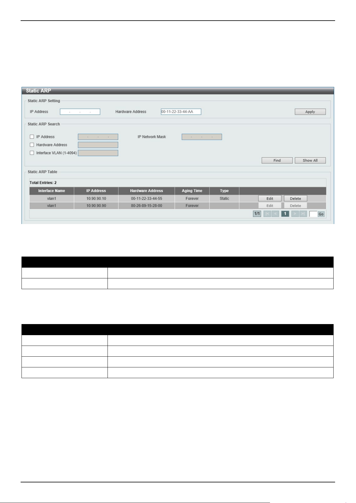
DGS-1520 Series Gigabit Ethernet Smart Managed Switch Web UI Reference Guide
219
Static ARP
This window is used to display and configure the static ARP settings.
To view the following window, click L3 Features > ARP > Static ARP, as shown below:
Figure 6-2 Static ARP Window
The fields that can be configured in the Static ARP Setting section are described below:
Parameter Description
IP Address
Enter the IP address that will be associated with the MAC address here.
Hardware Address
Enter the MAC address that will be associated with the IP address here.
Click the Apply button to accept the changes made.
The fields that can be configured in the Static ARP Search section are described below:
Parameter Description
IP Address
Select and enter the IP address of the static ARP entry here.
IP Network Mask
Select and enter the subnet mask of the static ARP entry here.
Hardware Address
Select and enter the MAC address of the static ARP entry here.
Interface VLAN
Select and enter the interface VLAN ID for the search here.
Click the Find button to find and display the entries, based on the information entered, in the Static ARP Table.
Click the Show All button to display all the static ARP entries in the Static ARP Table.
Click the Edit button to re-configure the specific entry.
Click the Delete button to remove the specific entry.
Enter a page number and click the Go button to navigate to a specific page when multiple pages exist.
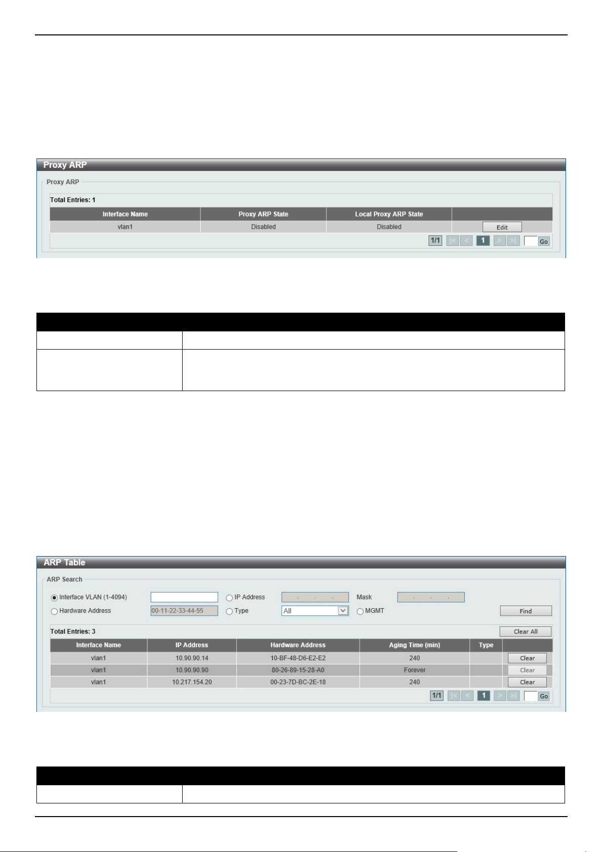
DGS-1520 Series Gigabit Ethernet Smart Managed Switch Web UI Reference Guide
220
Proxy ARP
This window is used to display and configure the Proxy ARP settings. The Proxy ARP feature will allow the Switch to
reply to ARP requests destined for another device by faking its identity (IP and MAC Address) as the original ARP
responder. Therefore, the Switch can then route packets to the intended destination without configuring static routing
or a default gateway. The host, usually a Layer 3 Switch, will respond to packets destined for another device.
To view the following window, click L3 Features > ARP > Proxy ARP, as shown below:
Figure 6-3 Proxy ARP Window
The fields that can be configured are described below:
Parameter Description
Proxy ARP State
Select to enable or disable the Proxy ARP state here.
Local Proxy ARP State
Select to enable or disable the local Proxy ARP state here. This local Proxy ARP
function allows the Switch to respond to the Proxy ARP, if the source IP and
destination IP are in the same interface.
Click the Edit button to re-configure the specific entry.
Click the Apply button to accept the changes made.
Enter a page number and click the Go button to navigate to a specific page when multiple pages exist.
ARP Table
This window is used to display and configure the ARP table settings.
To view the following window, click L3 Features > ARP > ARP Table, as shown below:
Figure 6-4 ARP Table Window
The fields that can be configured are described below:
Parameter Description
Interface VLAN Enter the interface VLAN ID used here. This value must be between 1 and 4094.
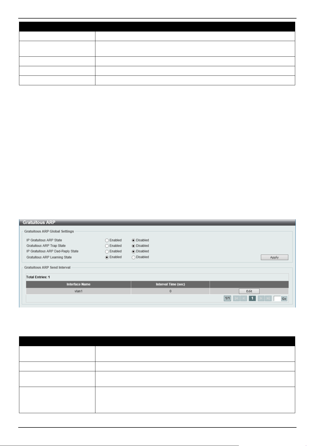
DGS-1520 Series Gigabit Ethernet Smart Managed Switch Web UI Reference Guide
221
Parameter Description
IP Address
Select and enter the IP address to display here.
Mask After the IP Address option was selected, enter the mask address for the IP
address here.
Hardware Address
Select and enter the MAC address to display here.
Type Select the Type option here. Options to choose from are All and Dynamic.
Mgmt
Select this option to display the Management port information.
Click the Find button to locate a specific entry based on the information entered.
Click the Clear All button to clear all dynamic ARP cache.
Click the Clear button to clear the dynamic ARP cache associated with the specific entry.
Enter a page number and click the Go button to navigate to a specific page when multiple pages exist.
Gratuitous ARP
This window is used to display and configure the gratuitous ARP settings. A gratuitous ARP request packet is an ARP
request packet where the source and the destination IP address are both set to the IP address of the sending device
and the destination MAC address is the broadcast address.
Generally, a device uses the gratuitous ARP request packet to discover whether the IP address is duplicated by other
hosts or to preload or reconfigure the ARP cache entry of hosts connected to the interface.
To view the following window, click L3 Features > Gratuitous ARP, as shown below:
Figure 6-5 Gratuitous ARP Window
The fields that can be configured are described below:
Parameter Description
IP Gratuitous ARP State
Select to enable or disable the learning of gratuitous ARP packets in the ARP
cache table.
Gratuitous ARP Trap State
Select to enable or disable the gratuitous ARP feature trap state here.
IP Gratuitous ARP Dad-
Reply State
Select to enable or disable the IP gratuitous ARP Dad-reply state.
Gratuitous ARP Learning
State
Select to enable or disable the gratuitous ARP learning state. Normally, the system
will only learn ARP entries from ARP reply packets or a normal ARP request
packet that asks for the MAC address of the Switch IP address. This option used
to enable or disable the learning of ARP entries based on received gratuitous ARP
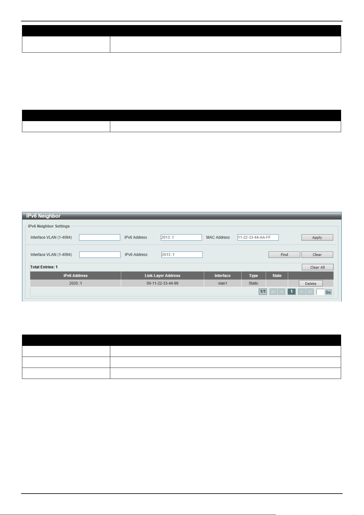
DGS-1520 Series Gigabit Ethernet Smart Managed Switch Web UI Reference Guide
222
Parameter Description
packets. The gratuitous ARP packet is sent by a source IP address and is identical
to the IP that the packet is querying.
Click the Apply button to accept the changes made.
Click the Edit button to re-configure the specific entry.
Enter a page number and click the Go button to navigate to a specific page when multiple pages exist.
After clicking the Edit button, the field that can be configured for Gratuitous ARP Send Interval is described below:
Parameter Description
Interval Time
Enter the gratuitous ARP sending interval time, in seconds, here.
Click the Apply button to accept the changes made.
IPv6 Neighbor
This window is used to display and configure the IPv6 neighbor settings.
To view the following window, click L3 Features > IPv6 Neighbor, as shown below:
Figure 6-6 IPv6 Neighbor Window
The fields that can be configured are described below:
Parameter Description
Interface VLAN
Enter the VLAN interface ID here.
IPv6 Address
Enter the IPv6 address.
MAC Address
Enter the MAC address.
Click the Apply button to accept the changes made.
Click the Find button to locate a specific entry based on the information entered.
Click the Clear button to clear all the dynamic information for the specific interface.
Click the Clear All button to clear all the dynamic IPv6 neighbor information in this table.
Click the Delete button to remove the specific entry.
Enter a page number and click the Go button to navigate to a specific page when multiple pages exist.
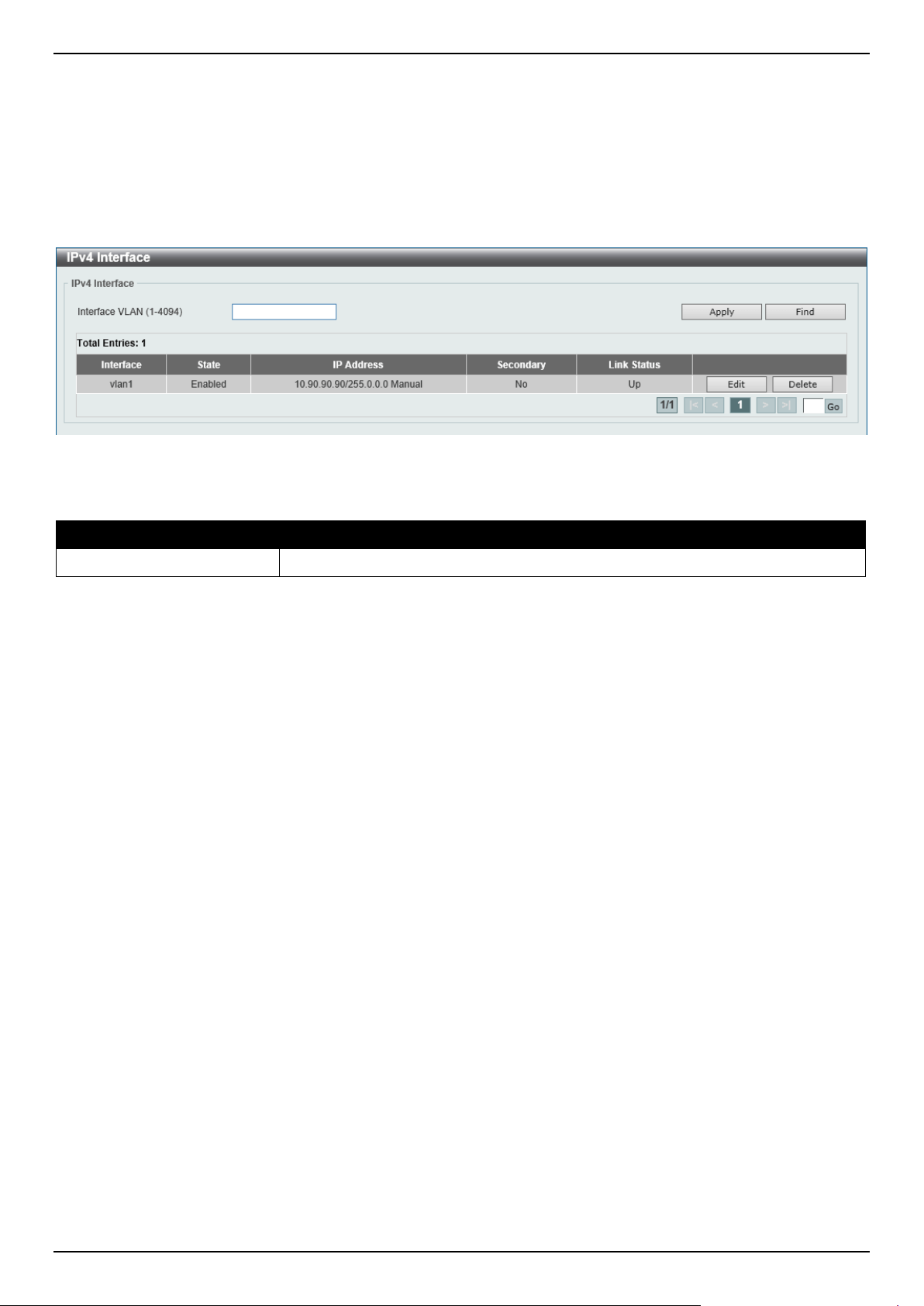
DGS-1520 Series Gigabit Ethernet Smart Managed Switch Web UI Reference Guide
223
Interface
IPv4 Interface
This window is used to display and configure the IPv4 interface settings.
To view the following window, click L3 Features > Interface > IPv4 Interface, as shown below:
Figure 6-7 IPv4 Interface Window
The fields that can be configured are described below:
Parameter Description
Interface VLAN
Enter the interface VLAN ID here. This value must be between 1 and 4094.
Click the Apply button to accept the changes made.
Click the Find button to locate a specific entry based on the information entered.
Click the Edit button to re-configure the specific entry.
Click the Delete button to remove the specific entry.
Enter a page number and click the Go button to navigate to a specific page when multiple pages exist.
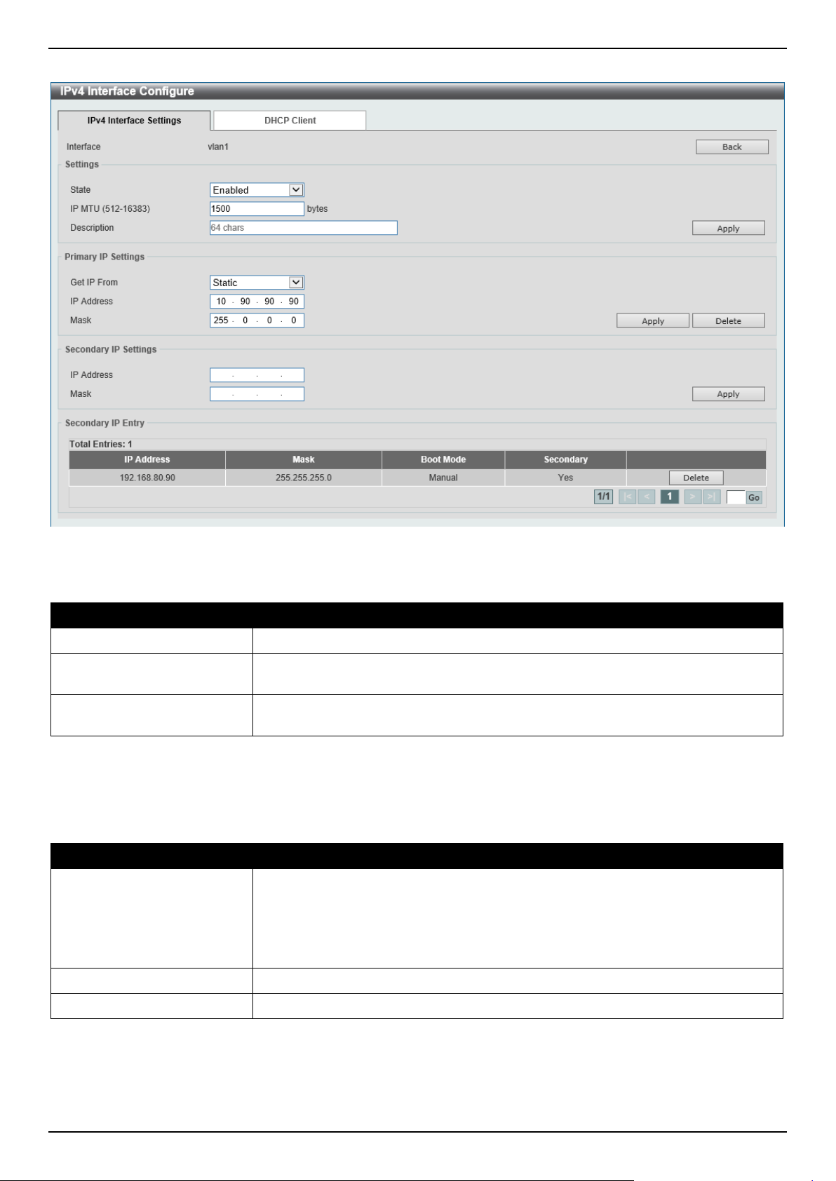
DGS-1520 Series Gigabit Ethernet Smart Managed Switch Web UI Reference Guide
224
After clicking the Edit button, the following page will be available.
Figure 6-8 IPv4 Interface (Edit) Window
The fields that can be configured in the Settings section are described below:
Parameter Description
State
Select to enable or disable the IPv4 interface global state.
IP MTU
Enter the MTU value here. The range is from 512 to 16383 bytes. By default, this
value is 1500 bytes.
Description
Enter the description for this entry here. This string can be up to 64 characters
long.
Click the Back button to return to the previous window.
Click the Apply button to accept the changes made.
The fields that can be configured in the Primary IP Settings section are described below:
Parameter Description
Get IP From
Select the get IP from option here. Options to choose from are:
• Static - Enter the IPv4 address of this interface manually in the fields
provided.
• DHCP - This interface will obtain IPv4 information automatically from the
DHCP server located on the local network.
IP Address
Enter the primary IPv4 address for this interface here.
Mask
Enter the primary IPv4 subnet mask for this interface here.
Click the Apply button to accept the changes made.
Click the Delete button to remove the specific entry.
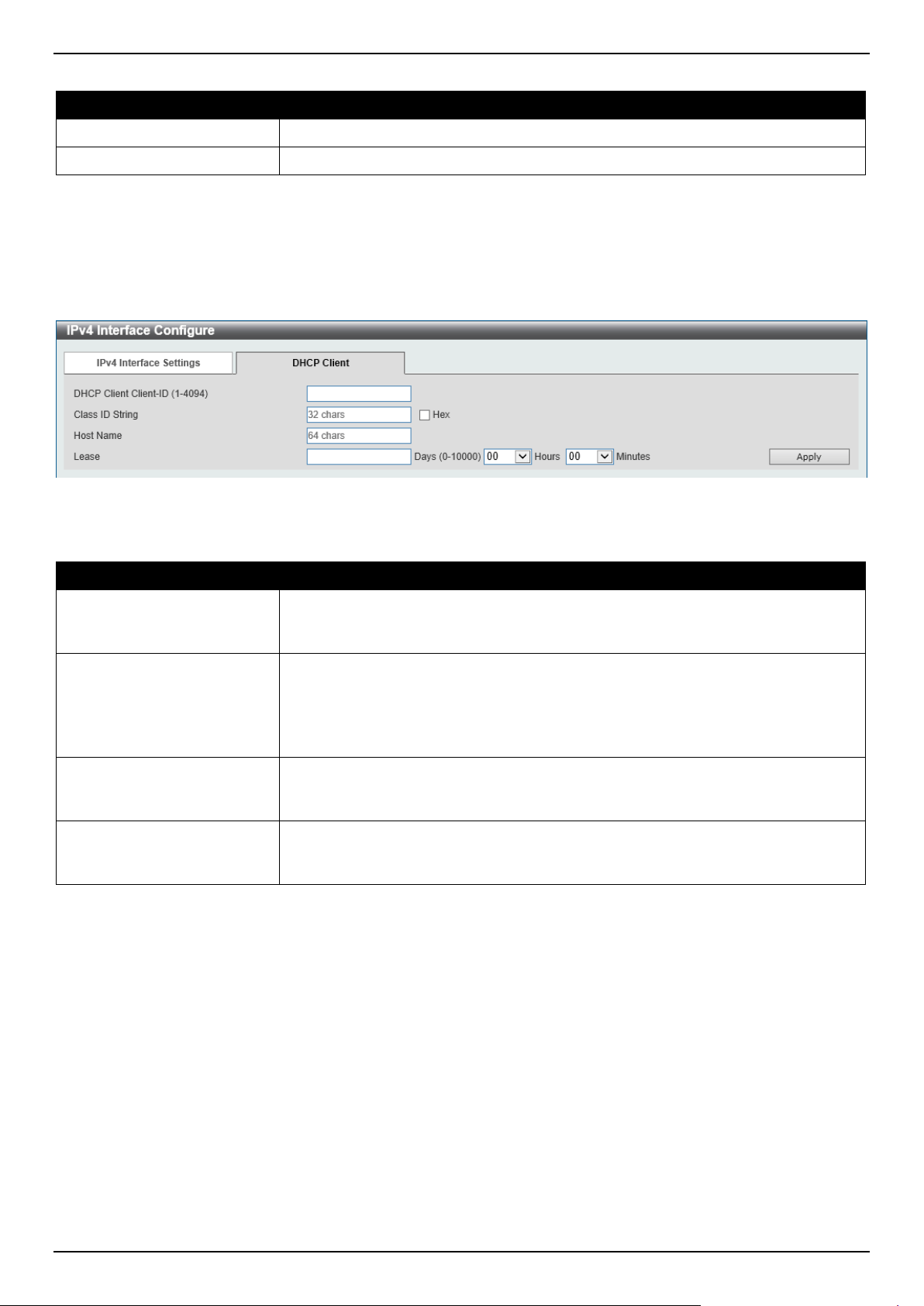
DGS-1520 Series Gigabit Ethernet Smart Managed Switch Web UI Reference Guide
225
The fields that can be configured in the Secondary IP Settings section are described below:
Parameter Description
IP Address
Enter the secondary IPv4 address for this interface here.
Mask
Enter the secondary IPv4 subnet mask for this interface here.
Click the Apply button to accept the changes made.
Click the Delete button to remove the specific entry.
Enter a page number and click the Go button to navigate to a specific page when multiple pages exist.
After selecting the DHCP Client tab, the following page will appear.
Figure 6-9 IPv4 Interface (Edit, DHCP Client) Window
The fields that can be configured are described below:
Parameter Description
DHCP Client Client-ID
Enter the DHCP Client ID here. The range is from 1 to 4094. This parameter is
used to specify the VLAN interface whose hexadecimal MAC address will be used
as the client ID sent with the discover message.
Class ID String
Enter the class ID string here. This string can be up to 32 characters long.
Select the Hex option to enter the Class ID string in the hexadecimal format. This
string can be up to 64 characters long. This parameter is used to specify the
vendor class identifier used as the value of Option 60 in the DHCP discover
message.
Host Name
Enter the host name here. This string can be up to 64 characters long. This
parameter is used to specify the value of the host name option to be sent with the
DHCP discover message.
Lease
Enter and optionally select the DHCP client lease time here. In the textbox, the
lease time, in days, can be entered. The range is from 0 to 10000 days. Hours and
Minutes can also be selected optionally.
Click the Apply button to accept the changes made.
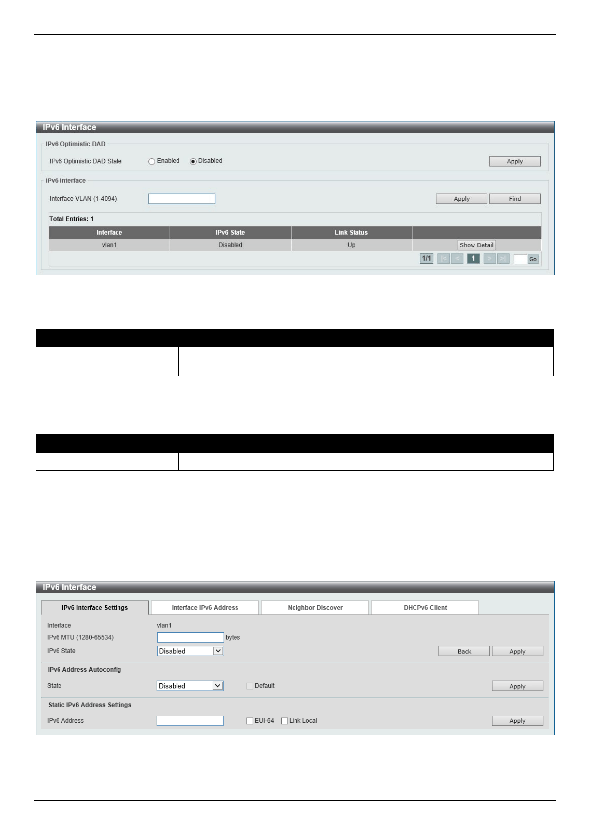
DGS-1520 Series Gigabit Ethernet Smart Managed Switch Web UI Reference Guide
226
IPv6 Interface
This window is used to display and configure the IPv6 interface settings.
To view the following window, click L3 Features > Interface > IPv6 Interface, as shown below:
Figure 6-10 IPv6 Interface Window
The fields that can be configured in IPv6 Optimistic DAD are described below:
Parameter Description
IPv6 Optimistic DAD State
Select to enable or disable the IPv6 Optimistic Duplicate Address Detection (DAD)
state here.
Click the Apply button to accept the changes made.
The fields that can be configured in IPv6 Interface are described below:
Parameter Description
Interface VLAN
Enter the VLAN interface ID that will be associated with the IPv6 entry.
Click the Apply button to accept the changes made.
Click the Find button to locate a specific entry based on the information entered.
Click the Show Detail button to view and configure detailed settings for the IPv6 interface entry.
Enter a page number and click the Go button to navigate to a specific page when multiple pages exist.
After clicking the Show Detail button, the following page will be available.
Figure 6-11 IPv6 Interface (Detail, IPv6 Interface Settings) Window
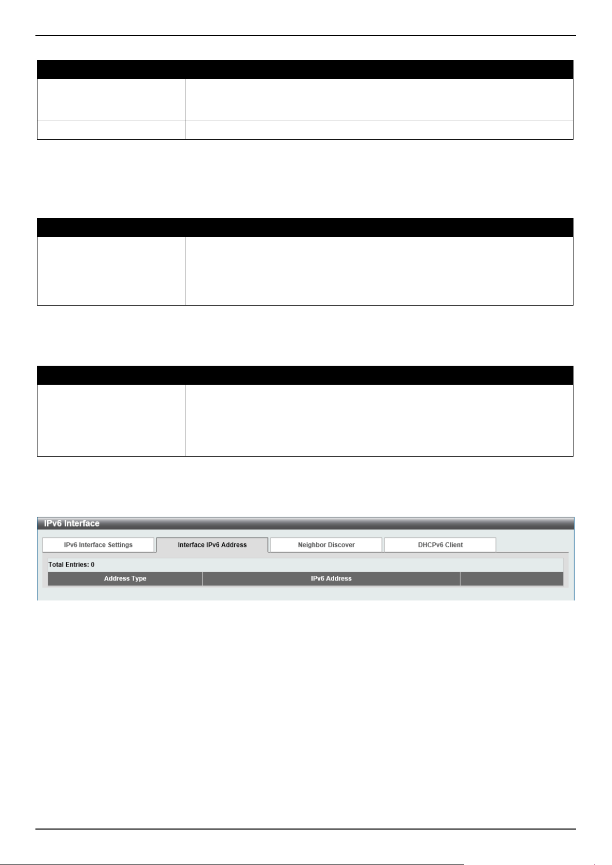
DGS-1520 Series Gigabit Ethernet Smart Managed Switch Web UI Reference Guide
227
The fields that can be configured are described below:
Parameter Description
IPv6 MTU
Enter the IPv6 MTU value here. The range is from 1280 to 65534 bytes. By
default, this value is 1500 bytes. This parameter is used to configure the MTU to
be advertised in RA messages.
IPv6 State
Select to enable or disable the IPv6 interface global state here.
Click the Back button to discard the changes made and return to the previous page.
Click the Apply button to accept the changes made.
The fields that can be configured for IPv6 Address Autoconfig are described below:
Parameter Description
State
Select to enable or disable the automatic configuration of the IPv6 address using
stateless auto-configuration here.
Select the Default option to specify that if the default router is selected on this
interface, a default route will be installed using that default router. This option can
only be specified on one interface.
Click the Apply button to accept the changes made.
The fields that can be configured for Static IPv6 Address Settings are described below:
Parameter Description
IPv6 Address
Enter the IPv6 address for this IPv6 interface here.
Select the EUI-64 option to configure an IPv6 address on the interface using the
EUI-64 interface ID.
Select the Link Local option to configure a link-local address for the IPv6
interface.
Click the Apply button to accept the changes made.
After selecting the Interface IPv6 Address tab option, at the top of the page, the following page will be available.
Figure 6-12 IPv6 Interface (Detail, Interface IPv6 Address) Window
Click the Delete button to delete the specified entry.
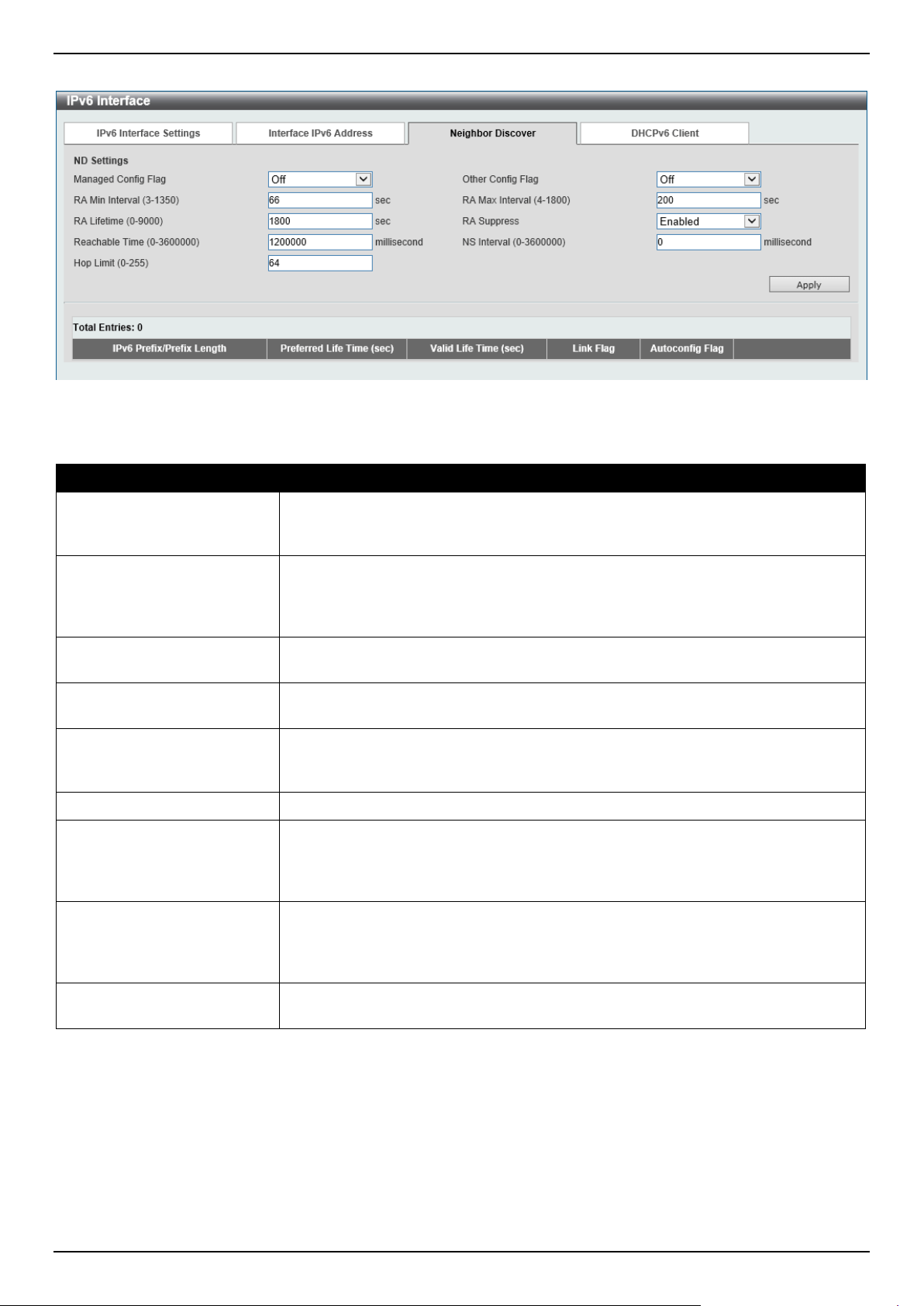
DGS-1520 Series Gigabit Ethernet Smart Managed Switch Web UI Reference Guide
228
After selecting the Neighbor Discover tab option, at the top of the page, the following page will be available.
Figure 6-13 IPv6 Interface (Detail, Neighbor Discover) Window
The fields that can be configured for ND Settings are described below:
Parameter Description
Managed Config Flag Turn the Managed Config Flag option On or Off here. When the neighbor host
receives the RA which has flag turned on, the host should use a stateful
configuration protocol to obtain IPv6 addresses.
Other Config Flag Turn the Other Config Flag option On or Off here. By setting the other
configuration flag on, the router instructs the connected hosts to use a stateful
configuration protocol to obtain auto-configuration information other than the IPv6
address.
RA Min Interval
Enter the minimum RA interval time value here. The range is from 3 to 1350
seconds. This value must be smaller than 0.75 times the maximum value.
RA Max Interval
Enter the maximum RA interval time value here. The range is from 4 to 1800
seconds.
RA Lifetime
Enter the RA lifetime value here. The range is from 0 to 9000 seconds. The lifetime
value in RA instructs the received host the lifetime value for taking the router as
the default router.
RA Suppress
Select to enable or disable the RA suppress feature here.
Reachable Time
Enter the Reachable Time here. The range is from 0 to 3600000 milliseconds. If
the specified time is 0, the router will use 1200 seconds on the interface and
advertise 0 (unspecified) in the RA message. The Reachable Time is used by the
IPv6 node in determining the reachability of the neighbor nodes.
NS Interval
Enter the Neighbor Solicitation (NS) interval value here. The range is from 0 to
3600000 milliseconds, in multiples of 1000. If the specified time is 0, the router will
use 1 second on the interface and advertise 0 (unspecified) in the Router
Advertisement (RA) message.
Hop Limit
Enter the hop limit value here. The range is from 0 to 255. The IPv6 packet
originated by the system will also use this value as the initial hop limit.
Click the Apply button to accept the changes made.

DGS-1520 Series Gigabit Ethernet Smart Managed Switch Web UI Reference Guide
229
After selecting the DHCPv6 Client tab option, at the top of the page, the following page will be available.
Figure 6-14 IPv6 Interface (Detail, DHCPv6 Client) Window
Click the Restart button to restart the DHCPv6 client service.
The fields that can be configured for DHCPv6 Client Settings are described below:
Parameter Description
Client State
Select to enable or disable the DHCPv6 client service here.
Select the Rapid Commit option to proceed with two-message exchange for
address delegation. The rapid-commit option will be included in the Solicit
message to request a two-message handshake.
Click the Apply button to accept the changes made.
The fields that can be configured for DHCPv6 Client PD Settings are described below:
Parameter Description
Client PD State
Select to enable or disable the DHCPv6 client process that requests a Prefix
Delegation (PD) through a specified interface.
Select the Rapid Commit option to proceed with two-message exchange for prefix
delegation. The rapid-commit option will be included in the Solicit message to
request a two-message handshake.
General Prefix Name
Enter the IPv6 general prefix name here. This name can be up to 12 characters
long.
IPv6 DHCP Client PD Hint
Enter the IPv6 prefix to be sent in the message as a hint here.
Click the Apply button to accept the changes made.
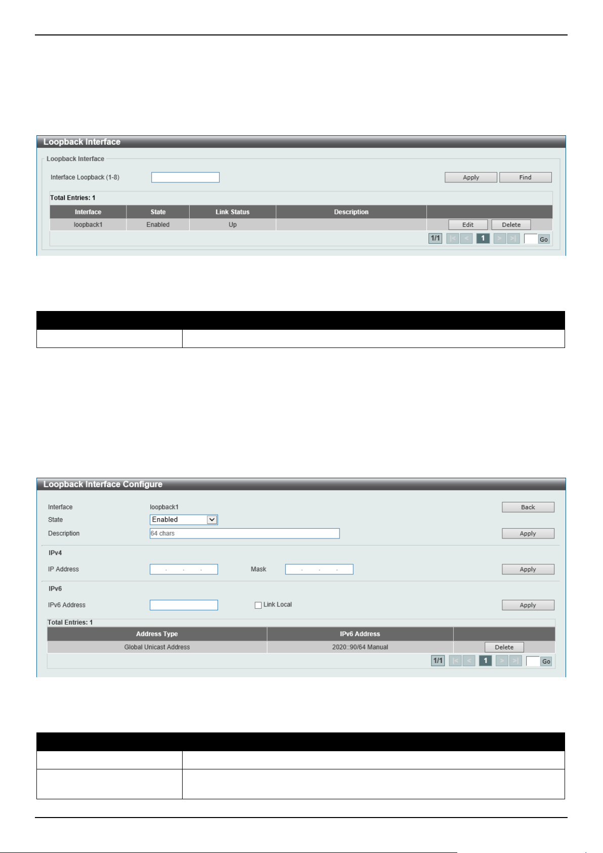
DGS-1520 Series Gigabit Ethernet Smart Managed Switch Web UI Reference Guide
230
Loopback Interface
This window is used to display and configure the loopback interface settings. A loopback interface is a software only
interface, which always stays in the up status
To view the following window, click L3 Features > Interface > Loopback Interface, as shown below:
Figure 6-15 Loopback Interface Window
The fields that can be configured are described below:
Parameter Description
Interface Loopback
Enter the loopback interface ID here. The range is from 1 to 8.
Click the Apply button to accept the changes made.
Click the Find button to locate a specific entry based on the information entered.
Click the Edit button to modify the specified entry.
Click the Delete button to delete the specified entry.
Enter a page number and click the Go button to navigate to a specific page when multiple pages exist.
After clicking the Edit button, the following page will appear.
Figure 6-16 Loopback Interface (Edit) Window
The fields that can be configured are described below:
Parameter Description
State
Select to enable or disable the loopback interface here.
Description
Enter the description for the loopback interface here. This string can be up to 64
characters long.
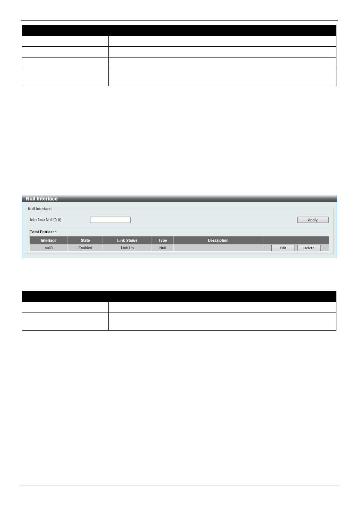
DGS-1520 Series Gigabit Ethernet Smart Managed Switch Web UI Reference Guide
231
Parameter Description
IP Address
Enter the IPv4 address associated with this loopback interface here.
Mask
Enter the IPv4 subnet mask associated with this loopback interface here.
IPv6 Address
Enter the IPv6 address associated with this loopback interface here.
Link Local
Select this option to specify that the IPv6 address entered is the link-local IPv6
address.
Click the Back button to return to the previous window.
Click the Apply button to accept the changes made.
Click the Delete button to delete the specified entry.
Enter a page number and click the Go button to navigate to a specific page when multiple pages exist.
Null Interface
This window is used to display and configure the Null interface settings.
To view the following window, click L3 Features > Interface > Null Interface, as shown below:
Figure 6-17 Null Interface Window
The fields that can be configured are described below:
Parameter Description
Interface Null
Enter the Null interface ID here. This value can only be 0.
Description After clicking the Edit button, enter the description for the Null interface here. This
string can be up to 64 characters long.
Click the Apply button to accept the changes made.
Click the Edit button to modify the description for the Null interface.
Click the Delete button to delete the specified entry.
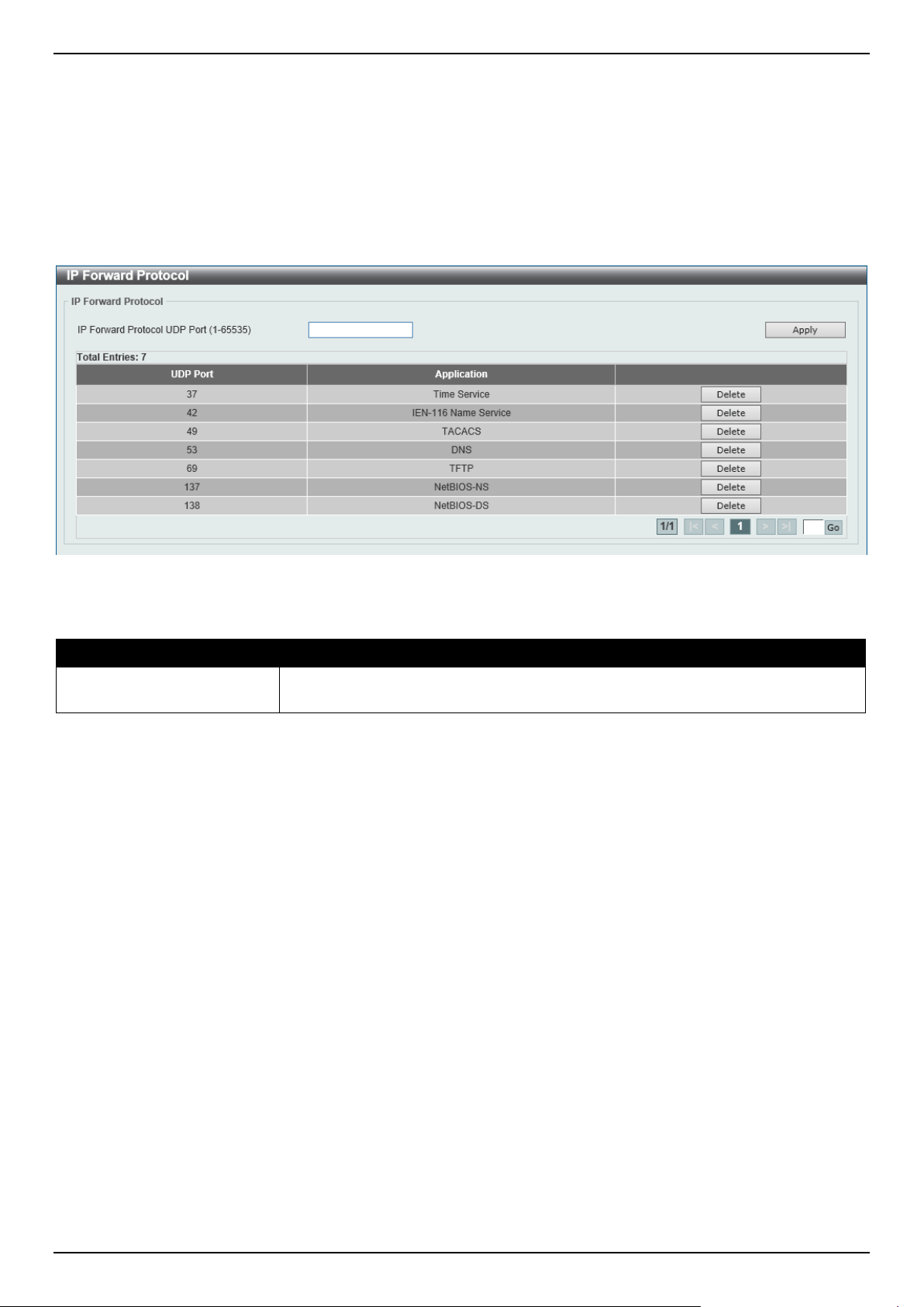
DGS-1520 Series Gigabit Ethernet Smart Managed Switch Web UI Reference Guide
232
UDP Helper
IP Forward Protocol
This window is used to display and configure the IP forward protocol settings. This feature is used to enable the
forwarding of a specific UDP service type of packets.
To view the following window, click L3 Features > UDP Helper > IP Forward Protocol, as shown below:
Figure 6-18 IP Forward Protocol Window
The fields that can be configured are described below:
Parameter Description
IP Forward Protocol UDP
Port
Enter the destination port of the UDP service to be forwarded here. The range is
from 1 to 65535.
Click the Apply button to accept the changes made.
Click the Delete button to delete the specified entry.
Enter a page number and click the Go button to navigate to a specific page when multiple pages exist.
IP Helper Address
This window is used to add or remove a target address for the forwarding of UDP broadcast packets. This feature
takes effect only when the received interface has an IP address assigned.
The system only forwards packets that satisfy the following restrictions:
• The destination MAC address must be a broadcast address.
• The destination IP address must be an all-one broadcast.
• The packets are IPv4 UDP packets.
• The IP TTL value must be greater than or equal to 2.
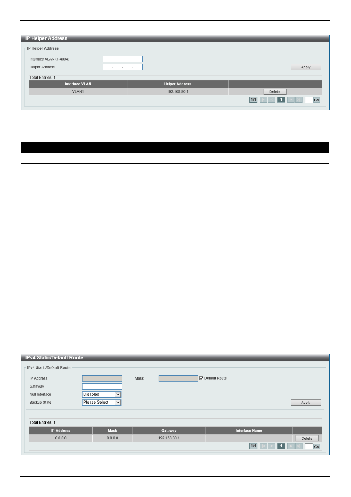
DGS-1520 Series Gigabit Ethernet Smart Managed Switch Web UI Reference Guide
233
To view the following window, click L3 Features > UDP Helper > IP Helper Address, as shown below:
Figure 6-19 IP Helper Address Window
The fields that can be configured are described below:
Parameter Description
Interface VLAN
Enter the VLAN interface ID used here. The range is from 1 to 4094.
Helper Address
Enter the target IPv4 address for the forwarding of the UDP broadcast packet here.
Click the Apply button to accept the changes made.
Click the Delete button to delete the specified entry.
Enter a page number and click the Go button to navigate to a specific page when multiple pages exist.
IPv4 Static/Default Route
This window is used to display and configure the IPv4 static and default route settings. The Switch supports static
routing for IPv4 formatted addressing. Users can create up to 512 static route entries for IPv4. For IPv4 static routes,
once a static route has been set, the Switch will send an ARP request packet to the next hop router that has been set
by the user. Once an ARP response has been retrieved by the Switch from that next hop, the route becomes enabled.
However, if the ARP entry already exists, an ARP request will not be sent.
The Switch also supports a floating static route, which means that the user may create an alternative static route with
a different next hop. This secondary next hop device route is considered as a backup static route when the primary
static route is down. If the primary route is lost, the backup route will become active and begin forwarding traffic.
Entries into the Switch's forwarding table can be made using an IP address, subnet mask, and gateway.
To view the following window, click L3 Features > IPv4 Static/Default Route, as shown below:
Figure 6-20 IPv4 Static/Default Route Window

DGS-1520 Series Gigabit Ethernet Smart Managed Switch Web UI Reference Guide
234
The fields that can be configured are described below:
Parameter Description
IP Address Enter the IPv4 address for this route here. Tick the Default Route option to use
the default route as the IPv4 address.
Mask
Enter the IPv4 network mask for this route here.
Gateway
Enter the gateway address for this route here.
Null Interface
Select to enable or disable the NULL interface here.
Backup State
Select the backup state option here. Options to choose from are:
• Primary - Specifies the route as the primary route to the destination.
• Backup - Specifies the route as the backup route to the destination.
• Weight - Specifies a weight number greater than zero, but less than the
maximum paths number. This number is used to replicate identical route
paths (multiple copies) in the routing table, so the paths get more chance of
being hit for traffic routing. Enter the weight value in the space provided. The
range is from 1 to 4.
Click the Apply button to accept the changes made.
Click the Delete button to remove the specific entry.
Enter a page number and click the Go button to navigate to a specific page when multiple pages exist.
IPv4 Route Table
This window is used to display and configure the IPv4 route table settings.
To view the following window, click L3 Features > IPv4 Route Table, as shown below:
Figure 6-21 IPv4 Route Table Window
The fields that can be configured are described below:
Parameter Description
IP Address
Select and enter the single IPv4 address here.
Network Address
Select and enter the IPv4 network address here. In the first space enter the
network prefix and in the second space enter the network mask.
RIP
Select this option to display only RIP routes.
OSPF
Select this option to display only OSPF routes.
Connected
Select this option to display only connected routes.
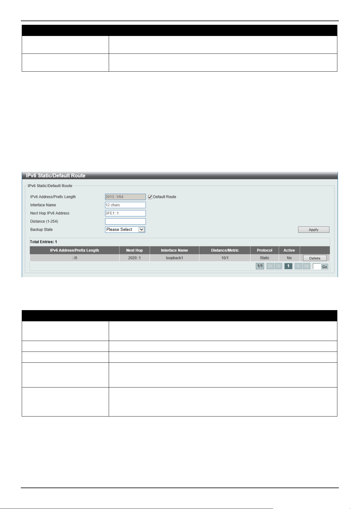
DGS-1520 Series Gigabit Ethernet Smart Managed Switch Web UI Reference Guide
235
Parameter Description
Hardware
Select this option to display only hardware routes. Hardware routes are routes that
have been written into the hardware chip.
Summary
Select this option to display a summary and count of the route sources configured
on this Switch.
Click the Find button to locate a specific entry based on the information entered.
Click the Show All button to display all IPv4 routes in the table.
Enter a page number and click the Go button to navigate to a specific page when multiple pages exist.
IPv6 Static/Default Route
This window is used to display and configure the IPv6 static or default routes.
To view the following window, click L3 Features > IPv6 Static/Default Route, as shown below:
Figure 6-22 IPv6 Static/Default Route Window
The fields that can be configured are described below:
Parameter Description
IPv6 Address/Prefix Length
Enter the IPv6 address and prefix length for this route here.
Select Default Route to use this route as the default route.
Interface Name
Enter the name of the interface that will be associated with this route here.
Next Hop IPv6 Address
Enter the next hop IPv6 address here.
Distance
Enter the administrative distance of the static route here. This value must be
between 1 and 254. A lower value represents a better route. By default, this value
is 1.
Backup State
Select the backup state option here. Options to choose from are:
• Primary - The route is specified as the primary route to the destination.
• Backup - The route is specified as the backup route to the destination.
Click the Apply button to accept the changes made.
Click the Delete button to remove the specific entry.
Enter a page number and click the Go button to navigate to a specific page when multiple pages exist.
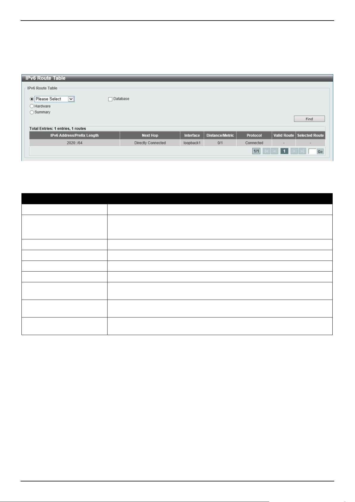
DGS-1520 Series Gigabit Ethernet Smart Managed Switch Web UI Reference Guide
236
IPv6 Route Table
This window is used to display and configure the IPv6 route table.
To view the following window, click L3 Features > IPv6 Route Table, as shown below:
Figure 6-23 IPv6 Route Table Window
The fields that can be configured are described below:
Parameter Description
IPv6 Address
Select and enter the IPv6 address to display here.
IPv6 Address/Prefix Length
Select and enter the IPv6 address and prefix length to display here. Select the
Longer Prefixes option to display IPv6 routes with prefixes greater than and equal
to the prefix length.
Interface Name
Select and enter the name of the interface to display here.
Connected
Select this option to display only connected routes.
RIPng
Select this option to display only RIPng routes.
OSPFv3
Select this option to display only OSPFv3 routes.
Database
Select this option to display all the related entries in the routing database instead
of just the best route.
Hardware
Select this option to display only hardware routes. Hardware routes are routes that
have been written into the hardware chip.
Summary
Select this option to display a summary and count of the route sources configured
on this Switch.
Click the Find button to locate a specific entry based on the information entered.
Enter a page number and click the Go button to navigate to a specific page when multiple pages exist.
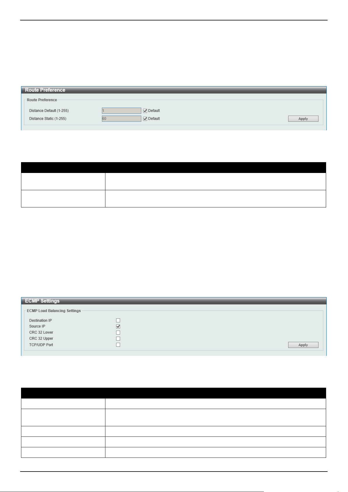
DGS-1520 Series Gigabit Ethernet Smart Managed Switch Web UI Reference Guide
237
Route Preference
This window is used to display and configure the route preference settings. Use this window to configure the distance,
which represents the route's trust rating. The route with a lower distance value is preferred over the route with a higher
distance value.
To view the following window, click L3 Features > Route Preference, as shown below:
Figure 6-24 Route Preference Window
The fields that can be configured are described below:
Parameter Description
Distance Default
Enter the administrative distance of default routes here. The range is from 1 to
255. By default, this value is 1.
Distance Static
Enter the administrative distance of static routes here. The range is from 1 to 255.
By default, this value is 60.
Click the Apply button to accept the changes made.
ECMP Settings
This window is used to display and configure the Equal-Cost Multi-Path (ECMP) routing settings. This is used to
configure the load balancing hash algorithm and used to determine the next hop entry for multiple paths destined for
the same destination.
To view the following window, click L3 Features > ECMP Settings, as shown below:
Figure 6-25 ECMP Settings Window
The fields that can be configured in ECMP Load Balancing Settings are described below:
Parameter Description
Destination IP
Select this option to use the destination IP address as the ECMP hash key.
Source IP
Select this option to use the least significant bits of the source IP address as the
ECMP hashing algorithm.
CRC 32 Lower
Select this option to use the lower bits of CRC-32 as the ECMP hashing algorithm.
CRC 32 Upper
Select this option to use the upper bits of CRC-32 as the ECMP hashing algorithm.
TCP/UDP Port
Select this option to use TCP/UDP port number as ECMP hash key.
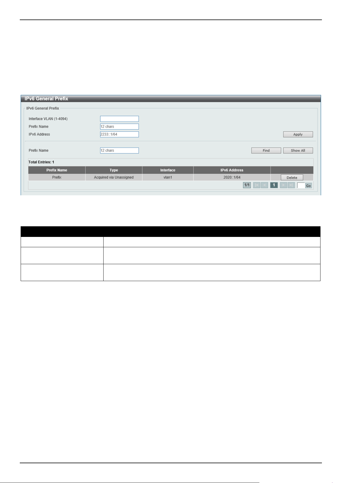
DGS-1520 Series Gigabit Ethernet Smart Managed Switch Web UI Reference Guide
238
Click the Apply button to accept the changes made.
IPv6 General Prefix
This window is used to display and configure the VLAN interface IPv6 general prefix settings.
To view the following window, click L3 Features > IPv6 General Prefix, as shown below:
Figure 6-26 IPv6 General Prefix Window
The fields that can be configured are described below:
Parameter Description
Interface VLAN
Enter the VLAN interface ID used here. The range is from 1 to 4094.
Prefix Name
Enter the IPv6 general prefix entry name here. This name can be up to 12
characters long.
IPv6 Address
Enter the IPv6 address and prefix length here. The prefix length of the IPv6
address is also the local subnet on the VLAN interface.
Click the Apply button to accept the changes made.
Click the Find button to locate a specific entry based on the information entered.
Click the Show All button to display all the IPv6 general prefix entries in the table.
Click the Delete button to delete the specified entry.
Enter a page number and click the Go button to navigate to a specific page when multiple pages exist.
URPF Settings
This window is used to display and configure the Unicast Reverse Path Forwarding (URPF) settings. One common
method to initiate an attack on a network is to utilize IPv4/IPv6 source address spoofing. When using this method,
traffic is sent into the network with a source address that is known or trusted by the target. If no protection exists, the
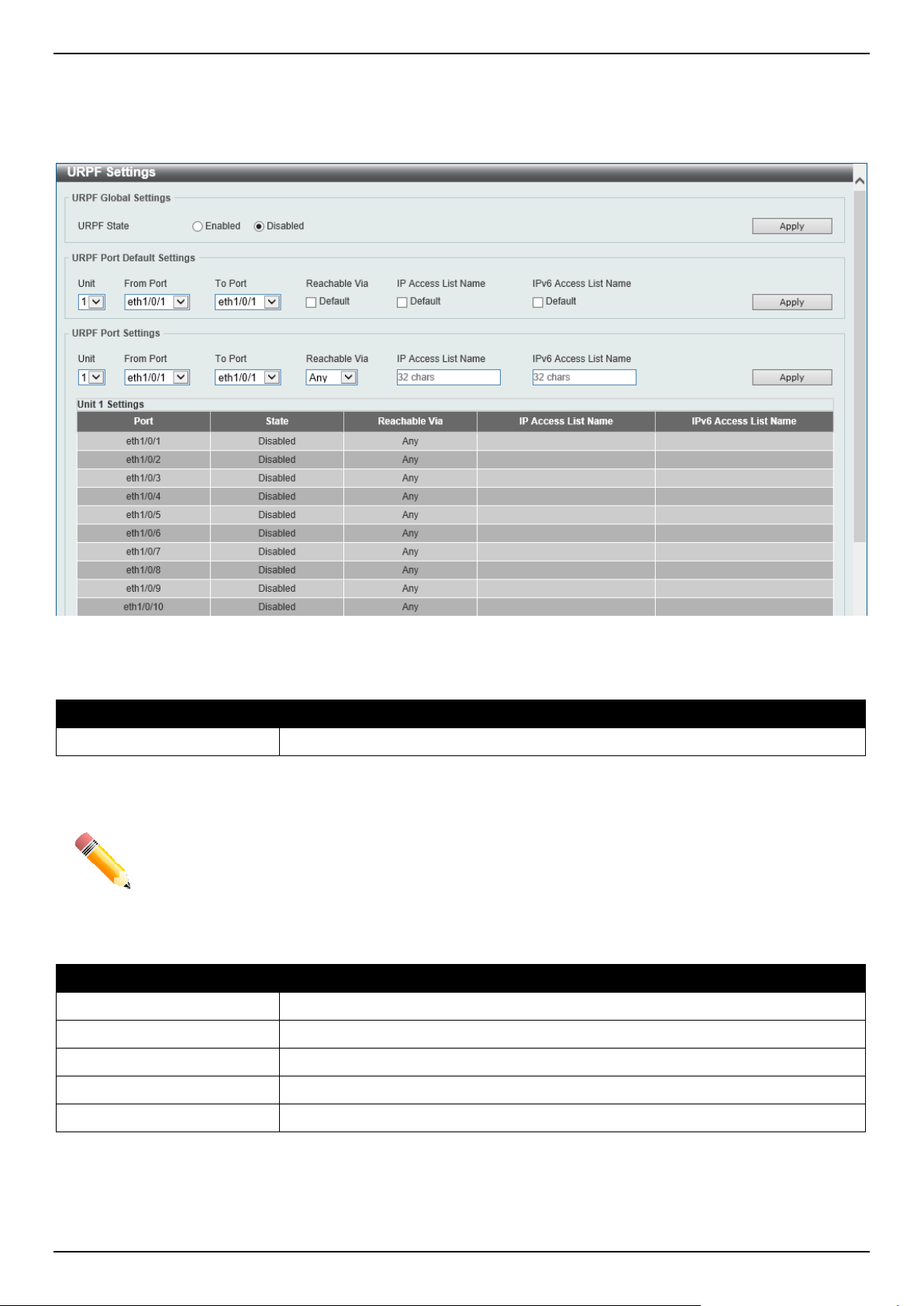
DGS-1520 Series Gigabit Ethernet Smart Managed Switch Web UI Reference Guide
239
organizational network will allow the traffic and potentially be open to a number of different attack types. Unicast RPF
helps to mitigate problems caused by malformed or forged IPv4/IPv6 source addresses passing through the router.
To view the following window, click L3 Features > URPF Settings, as shown below:
Figure 6-27 URPF Settings Window
The fields that can be configured in URPF Global Settings are described below:
Parameter Description
URPF State
Select to globally enable or disable the URPF state here.
Click the Apply button to accept the changes made.
NOTE: When enabled, the hardware routing table needs to be searched using the Session Initiation
Protocol (SIP) first and then using the Dynamic Inspection Protocol (DIP). This is achieved
by splitting the table into two halves so that the size of the IP routing table will be reduced by
half. This will not take effect until the configuration was saved and the Switch was rebooted.
The fields that can be configured in URPF Port Default Settings are described below:
Parameter Description
Unit
Select the Switch unit that will be used for this configuration here.
From Port - To Port
Select the range of ports that will be used for this configuration here.
Reachable Via
Select this option to use the default reachable via setting.
IP Access List Name
Select this option to use the default IP access list configuration.
IPv6 Access List Name
Select this option to use the default IPv6 access list configuration.
Click the Apply button to accept the changes made.
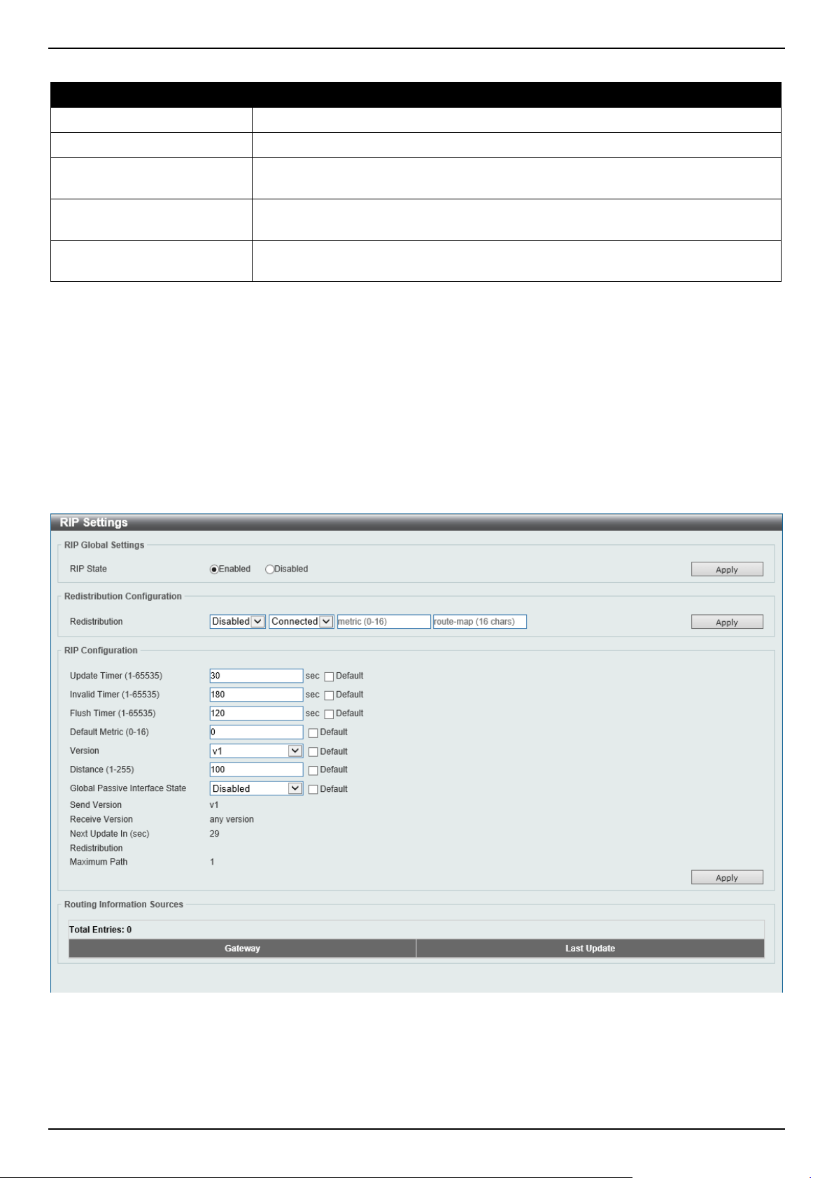
DGS-1520 Series Gigabit Ethernet Smart Managed Switch Web UI Reference Guide
240
The fields that can be configured in URPF Port Settings are described below:
Parameter Description
Unit
Select the Switch unit that will be used for this configuration here.
From Port - To Port
Select the range of ports that will be used for this configuration here.
Reachable Via
Specifies how URPF verifies if the source address is present in the routing table of
incoming packets (sometimes referred to as the loose mode).
IP Access List Name
Enter the name of the IP access list that will be used in the URPF check here. This
string can be up to 32 characters long.
IPv6 Access List Name
Enter the name of the IPv6 access list that will be used in the URPF check here.
This string can be up to 32 characters long.
Click the Apply button to accept the changes made.
RIP
RIP Settings
This window is used to display and configure Routing Information Protocol (RIP) settings.
To view the following window, click L3 Features > RIP > RIP Settings, as shown below:
Figure 6-28 RIP Settings Window

DGS-1520 Series Gigabit Ethernet Smart Managed Switch Web UI Reference Guide
241
The fields that can be configured in RIP Global Settings are described below:
Parameter Description
RIP State
Select to globally enable or disable the Routing Information Protocol (RIP) feature
here.
Click the Apply button to accept the changes made.
The fields that can be configured in Redistribution Configuration are described below:
Parameter Description
Redistribution
• First, select to enable or disable the RIP redistribution feature here.
• Second, select the routing protocol (domain) that will be redistributed into
RIP. Options to choose from are Connected, OSPF, and Static.
The Connected option refers to routes that are established automatically
through configuring an IP address on an interface.
The Static option means redistribute IP static routes.
• Third, enter the value to be used as the metric for the redistributed route
here. The range is from 0 to 16.
• Fourth, enter the Route Map name that is used in the filtering of the routes
to be redistributed to the current routing protocol. If not specified, all routes
are redistributed.
Click the Apply button to accept the changes made.
The fields that can be configured in RIP Configuration are described below:
Parameter Description
Update Time
Enter the update interval in seconds at which the update message is sent. The
range is from 1 to 65535 seconds. By default, this value is 30 seconds.
Select the Default option to use the default value here.
Invalid Time
Enter the invalid time value in seconds here. The range is from 1 to 65535
seconds. By default, this value is 180 seconds.
Select the Default option to use the default value here.
Flush Timer
Enter the flush timer value in seconds here. The range is from 1 to 65535 seconds.
By default, this value is 120 seconds.
Select the Default option to use the default value here.
Default Metric
Enter the default metric value here. The range is from 0 to 16. The default metric is
used in redistributing routes from other routing protocols. The routes being
redistributed are learned by other protocols and may have an incompatible metric
to RIP. The specifying of the metric allows the metric to be synced. By default, this
value is 0.
Select the Default option to use the default metric value.
Version
Select the global RIP version that will be used as the default version for all
interfaces here. Options to choose from are v1 (RIPv1) and v2 (RIPv2).
Select the Default option to specify that this feature should use the default
configuration. By default, RIPv1 and RIPv2 packets are received, but only RIPv1
packets are sent.
Distance
Enter the Administrative Distance for RIP here. The range is from 1 to 255. A lower
value represents a better route. By default, this value is 100.
Select the Default option to use the default Administrative Distance for RIP.
Global Passive Interface
State
Select to enable or disable the global passive interface function here. By default,
this option is disabled.
Select the Default option to return this function to the default state.
Click the Apply button to accept the changes made.
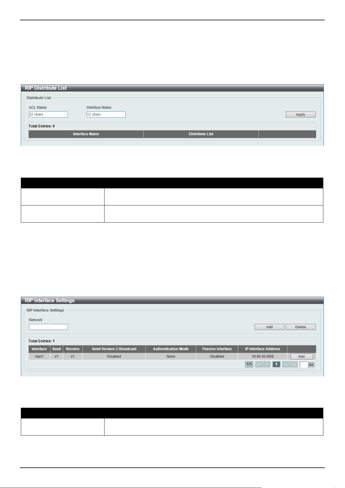
DGS-1520 Series Gigabit Ethernet Smart Managed Switch Web UI Reference Guide
242
RIP Distribute List
This window is used to display and configure the RIP distribution list settings.
To view the following window, click L3 Features > RIP > RIP Distribute List, as shown below:
Figure 6-29 RIP Distribute List Window
The fields that can be configured are described below:
Parameter Description
ACL Name
Enter the access list name that will be used here. This name can be up to 32
characters long.
Interface Name
Enter the interface name that will be used here. This name can be up to 12
characters long.
Click the Apply button to accept the changes made.
RIP Interface Settings
This window is used to display and configure the RIP interface settings.
To view the following window, click L3 Features > RIP > RIP Interface Settings, as shown below:
Figure 6-30 RIP Interface Settings Window
The fields that can be configured are described below:
Parameter Description
Network
Enter the IPv4 network address used by RIP here. Interfaces that have a subnet
belonging to the network specified here will be activated for RIP.
Click the Apply button to accept the changes made.
Click the Delete button to delete an entry based on the information entered.
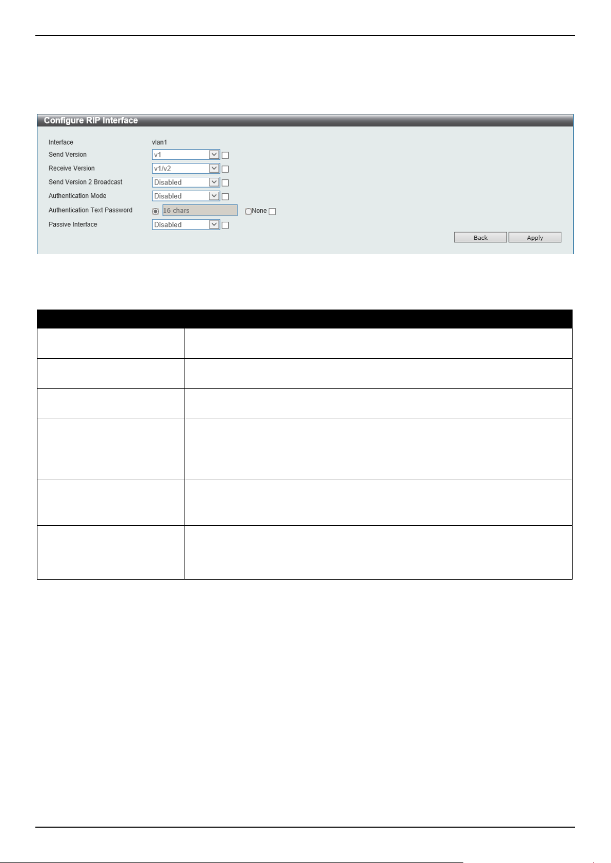
DGS-1520 Series Gigabit Ethernet Smart Managed Switch Web UI Reference Guide
243
Click the Edit button to configure the RIP interface settings for the specified entry.
Enter a page number and click the Go button to navigate to a specific page when multiple pages exist.
After clicking the Edit button, the following page will appear.
Figure 6-31 RIP Interface Settings (Edit) Window
The fields that can be configured are described below:
Parameter Description
Send Version
Select which version of RIP packets can be sent on the interface. Options to
choose from are v1 and v2.
Receive Version
Select which version of RIP packets can be received on the interface. Options to
choose from are v1, and v2, and v1/v2.
Send Version 2 Broadcast
Select to enable or disable the sending of version 2 RIP update packets as
broadcast packets instead of multicast packets.
Authentication Mode
Select to enable or disable the authentication mode here. Options to choose from
are:
• Disabled - Specifies to disable RIP authentication on the interface.
• Text - Specifies to enable RIP authentication on the interface.
Authentication Text
Password
After RIP authentication was enabled on the interface, select and enter the text
password here. This can be up to 16 characters long.
Select None to use an empty password.
Passive Interface
Select to enable or disable the passive interface function here. This is used to
disable the sending of routing updates on an interface. The Switch will not send
multicast RIP packets out through the interface however, RIP packets from other
routers received on this interface will continue to be processed.
Click the Apply button to accept the changes made.
Click the Back button to return to the previous window.
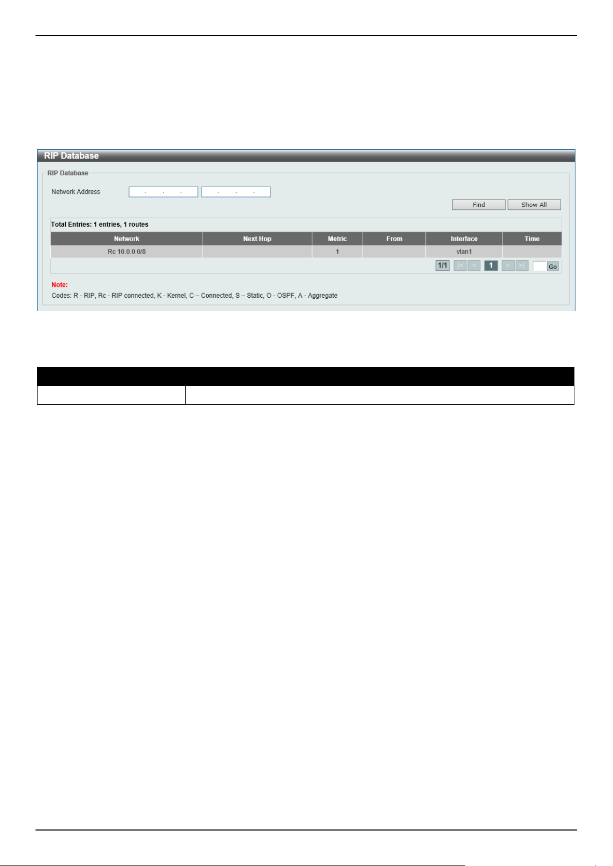
DGS-1520 Series Gigabit Ethernet Smart Managed Switch Web UI Reference Guide
244
RIP Database
This window is used to display the Routing Information Protocol (RIP) routing database. Summary address entries will
appear in the database only if relevant child routes exist and are being summarized. When the last child route for a
summary address becomes invalid, the summary address is also removed from the routing table.
To view the following window, click L3 Features > RIP > RIP Database, as shown below:
Figure 6-32 RIP Database Window
The fields that can be configured are described below:
Parameter Description
Network Address
Enter the subnet prefix and the prefix length of the network(s) to be displayed here.
Click the Find button to locate a specific entry based on the information entered.
Click the Show All button to display all the entries.
Enter a page number and click the Go button to navigate to a specific page when multiple pages exist.
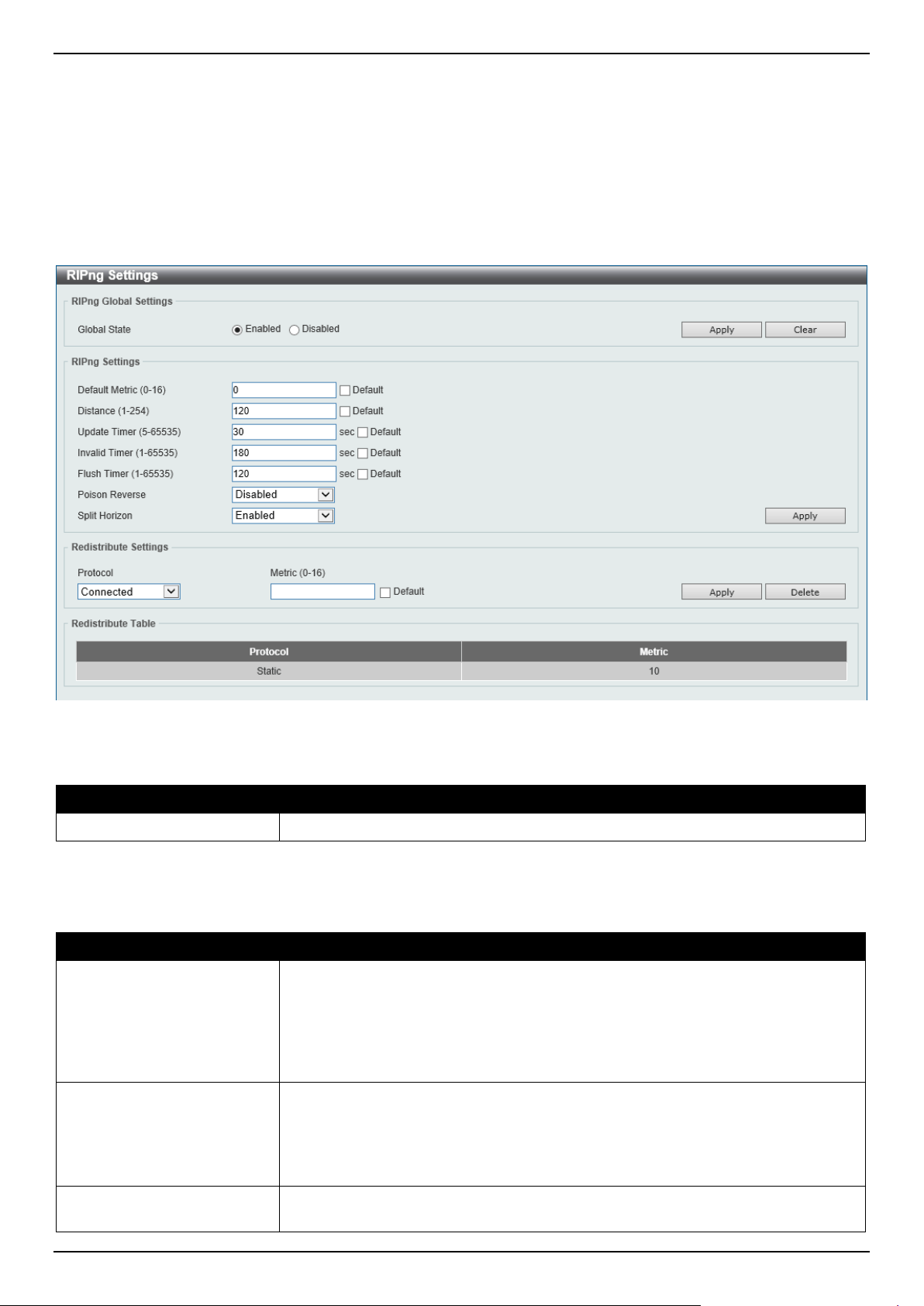
DGS-1520 Series Gigabit Ethernet Smart Managed Switch Web UI Reference Guide
245
RIPng
RIPng Settings
This window is used to display and configure the Routing Information Protocol Next Generation (RIPng) settings, also
known as IPv6 RIP.
To view the following window, click L3 Features > RIPng > RIPng Settings, as shown below:
Figure 6-33 RIPng Settings Window
The fields that can be configured in RIPng Global Settings are described below:
Parameter Description
Global State
Select to globally enable or disable the RIPng feature here.
Click the Apply button to accept the changes made.
The fields that can be configured in RIPng Settings are described below:
Parameter Description
Default Metric
Enter the default metric value here. The range is from 1 to 16. This value is used to
specify the default metric for routes redistributed from other routing protocols. If the
routes being redistributed are learned from other protocols, then they have an
incompatible metric with IPv6 RIP. Re-specifying of metric allows the metric to be
synced. By default, this value is 0.
Select the Default option to use the default metric value.
Distance
Enter the administrative distance for RIPng here. The range is from 1 to 254. The
distance value represents the trust rating of the route. The route with a lower
distance value is preferred over the route with the higher distance value. By
default, this value is 120.
Select the Default option to use the default administrative distance for RIPng.
Update Timer
Enter the update interval value at which the update message is sent here. The
range is from 5 to 65535 seconds. By default, this value is 30 seconds.
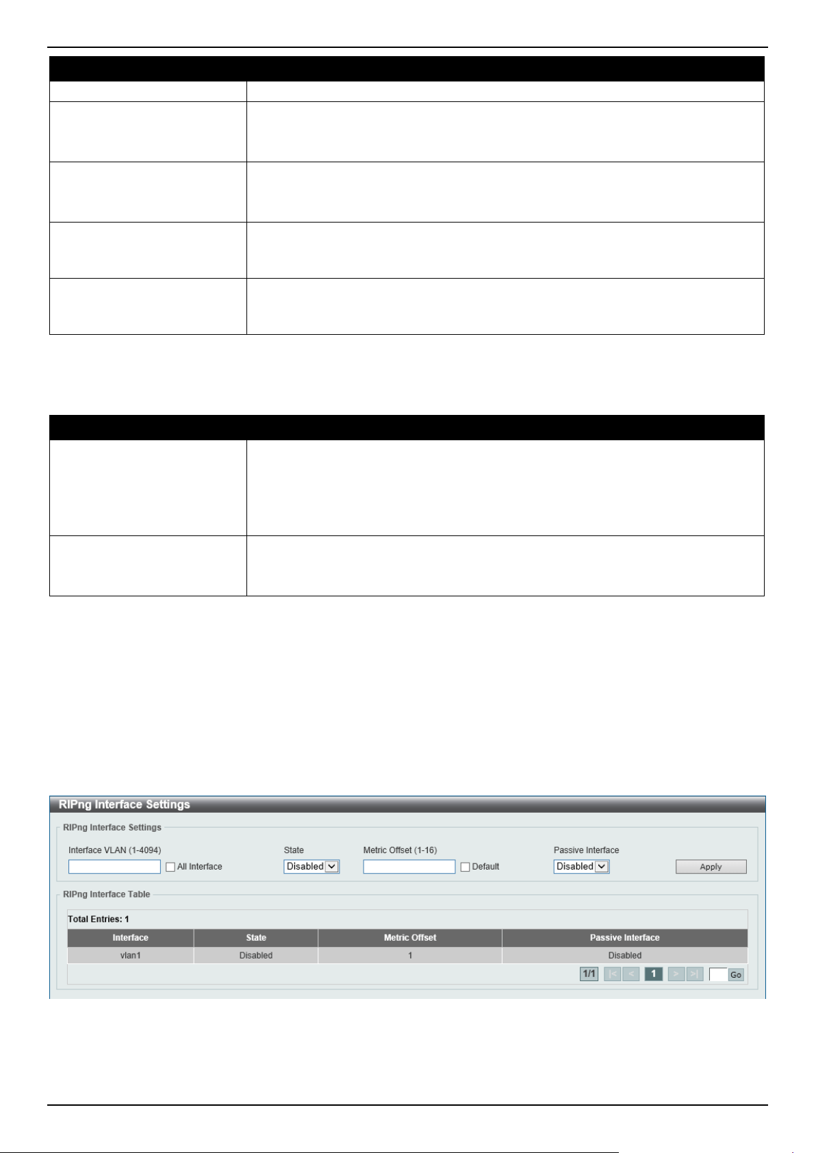
DGS-1520 Series Gigabit Ethernet Smart Managed Switch Web UI Reference Guide
246
Parameter Description
Select the Default option to use the default value here.
Invalid Timer
Enter the invalidate timer value in seconds here. The range is from 1 to 65535
seconds. By default, this value is 180 seconds.
Select the Default option to use the default value here.
Flush Timer
Enter the flush timer value in seconds here. The range is from 1 to 65535 seconds.
By default, this value is 120 seconds.
Select the Default option to use the default value here.
Poison Reverse
Select to enable or disable the Poison Reverse feature here. When Poison
Reverse is enabled, the routes learned from an interface will be advertised out to
the same interface with an unreachable metric.
Split Horizon
Select to enable or disable the Split Horizon feature here. When Split Horizon is
enabled, the routes learned from an interface will be not advertised out to the
same interface.
Click the Apply button to accept the changes made.
The fields that can be configured in Redistribute Settings are described below:
Parameter Description
Protocol
Select the protocol whose routes are to be redistributed here. Options to choose
from are Connected, Static, and OSPF.
The Static option means to redistribute IPv6 static routes.
The Connected option refers to routes that are established automatically by virtue
of configuring IPv6 address on an interface.
Metric
Enter the value to be used as the metric for the redistributed routes here. The
range is from 0 to 16.
Select the Default option to use the default metric value.
Click the Apply button to accept the changes made.
Click the Delete button to delete an entry based on the information entered.
RIPng Interface Settings
This window is used to display and configure the RIPng interface settings.
To view the following window, click L3 Features > RIPng > RIPng Interface Settings, as shown below:
Figure 6-34 RIPng Interface Settings Window
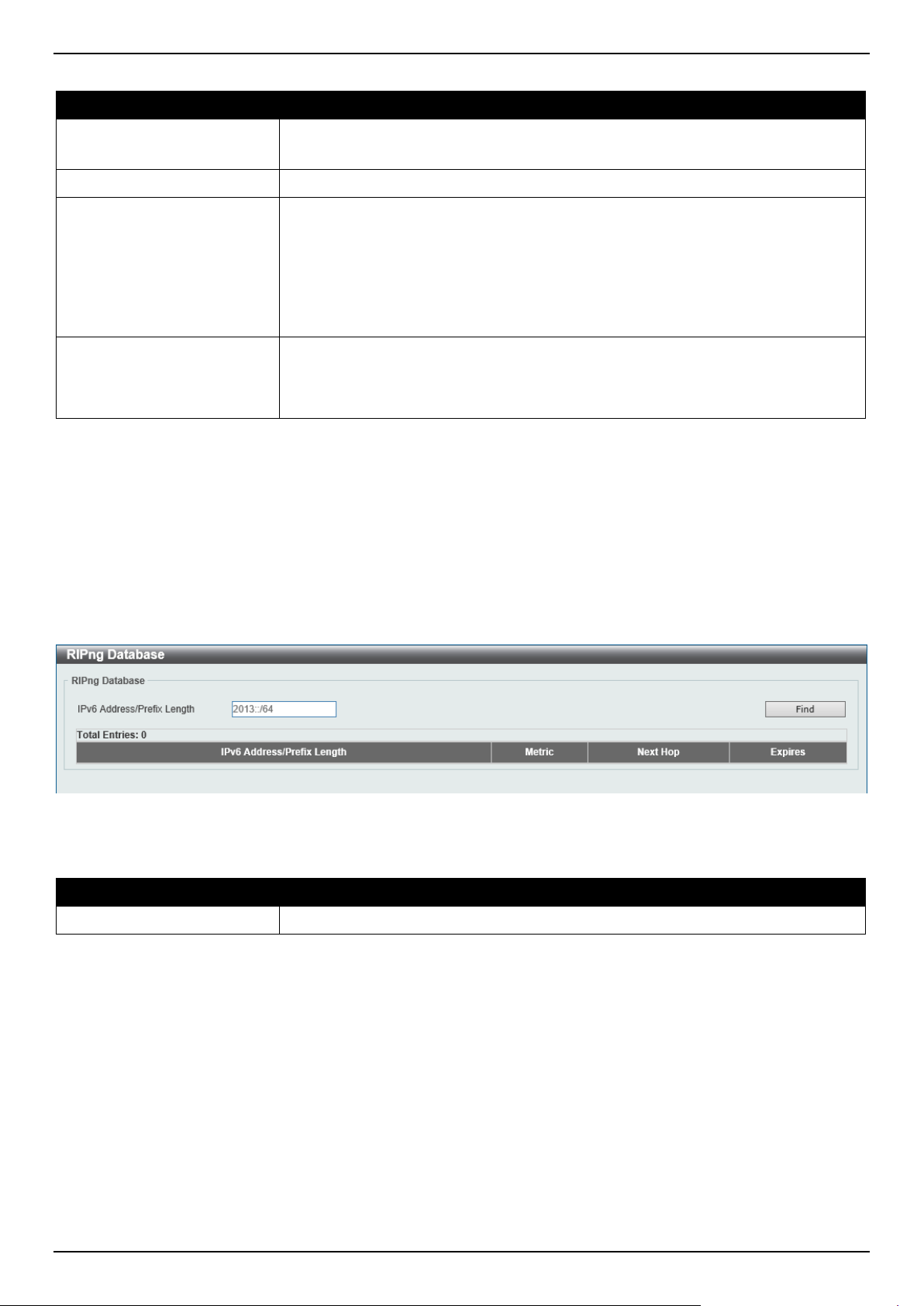
DGS-1520 Series Gigabit Ethernet Smart Managed Switch Web UI Reference Guide
247
The fields that can be configured are described below:
Parameter Description
Interface VLAN
Enter the VLAN interface ID here. The range is from 1 to 4094.
Select the All Interface option to use all available interfaces in this configuration.
State
Select to enable or disable the IPv6 RIP feature on the VLAN interface specified.
Metric Offset
Enter the value to be added to the metric of an IPv6 RIP route received on the
configured interface here. The range is from 1 to 16. The metric refers to the hop
count. By default, when receiving an IPv6 RIP route, a metric value of 1 is added
to the route before it is inserted into the routing table. Use this option to influence
the metric of routes received on different interfaces and influence the preference of
the route.
Select the Default option to use the default metric offset value.
Passive Interface
Select to enable or disable the passive interface feature here. If this option is
disabled, the router will not send RIPng packets out through the interface.
However, RIPng packets from other routers received on the interface will continue
to be processed.
Click the Apply button to accept the changes made.
Enter a page number and click the Go button to navigate to a specific page when multiple pages exist.
RIPng Database
This window is used to display the RIPng routing database.
To view the following window, click L3 Features > RIPng > RIPng Database, as shown below:
Figure 6-35 RIPng Database Window
The fields that can be configured are described below:
Parameter Description
IPv6 Address/Prefix Length
Enter the IPv6 address that will be used for these results here.
Click the Find button to locate a specific entry based on the information entered.
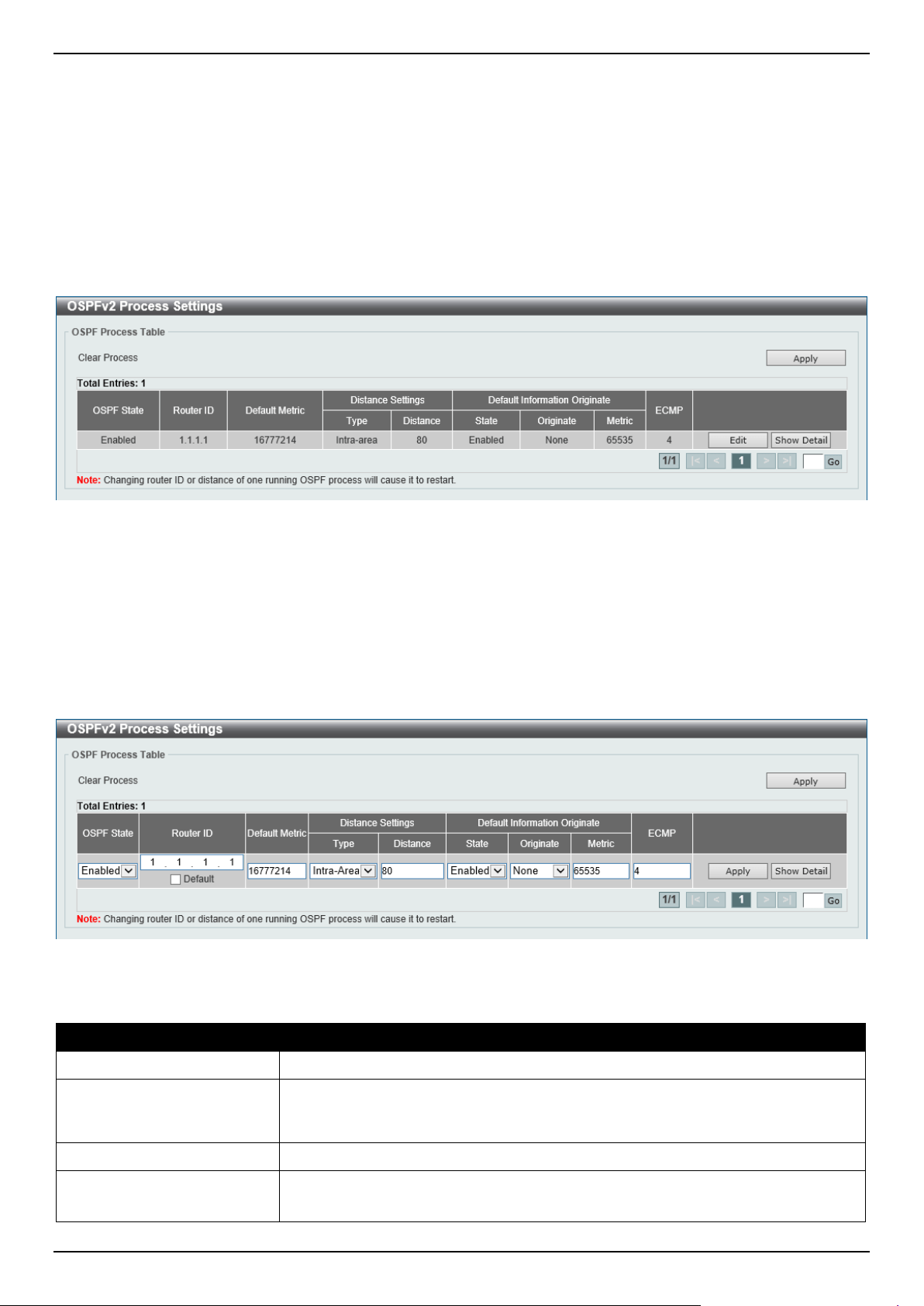
DGS-1520 Series Gigabit Ethernet Smart Managed Switch Web UI Reference Guide
248
OSPF
OSPFv2
OSPFv2 Process Settings
This window is used to display and configure the OSPFv2 process settings.
To view the following window, click L3 Features > OSPF > OSPFv2 > OSPFv2 Process Settings, as shown below:
Figure 6-36 OSPFv2 Process Settings Window
Click the Apply button to accept the changes made.
Click the Edit button to modify the specified entry.
Click the Show Detail button to view detailed information associated with the entry.
Enter a page number and click the Go button to navigate to a specific page when multiple pages exist.
After clicking the Edit button, the following page will appear.
Figure 6-37 OSPFv2 Process Settings (Edit) Window
The fields that can be configured are described below:
Parameter Description
OSPF State
Select to enable or disable the OSPFv2 state.
Router ID
Enter the router ID in the IPv4 address format here. The router ID is a 32-bit
number assigned to each router running the OSPF protocol. This number uniquely
identifies the router within an AS. Each router has a unique router ID.
Default Metric
Enter the default metric value used here. The range is from 1 to 16777214.
Type
Select the distance setting type here. Options to choose from are:
• Inter-Area - Specifies the distance for OSPF inter-area routes.
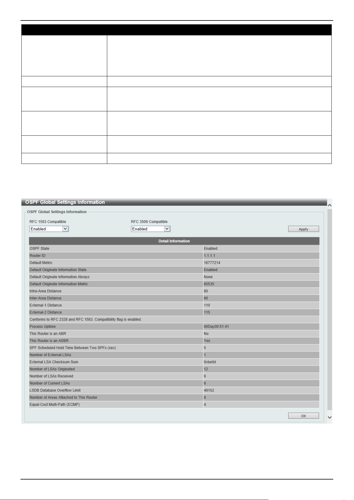
DGS-1520 Series Gigabit Ethernet Smart Managed Switch Web UI Reference Guide
249
Parameter Description
• Intra-Area - Specifies the distance for OSPF intra-area routes.
• External-1 - Specifies the distance for OSPF external type-5 and type-7
routes with a type-1 metric.
• External-2 - Specifies the distance for OSPF external type-5 and type-7
routes with a type-2 metric.
Distance
Enter the administrative distance value here. The range is from 1 to 255.
State
Select to enable or disable the Default Originate Information state here. This
feature is used to generate a default external route (type-5 LSA) network 0.0.0.0 to
the AS.
Originate Select the Originate option here. Options to choose from are Always and None.
Selecting the Always option specifies to always generate the default route
regardless of existence of a default route in the routing table.
Metric
Enter the cost value associated with the generated default route here. If not
specified, the default metric cost is 1. The range is from 1 to 65535.
ECMP
Enter the ECMP value for this process here. The range is from 1 to 4.
Click the Apply button to accept the changes made.
After clicking the Show Detail button, the following page will appear.
Figure 6-38 OSPFv2 Process Settings (Show Detail) Window
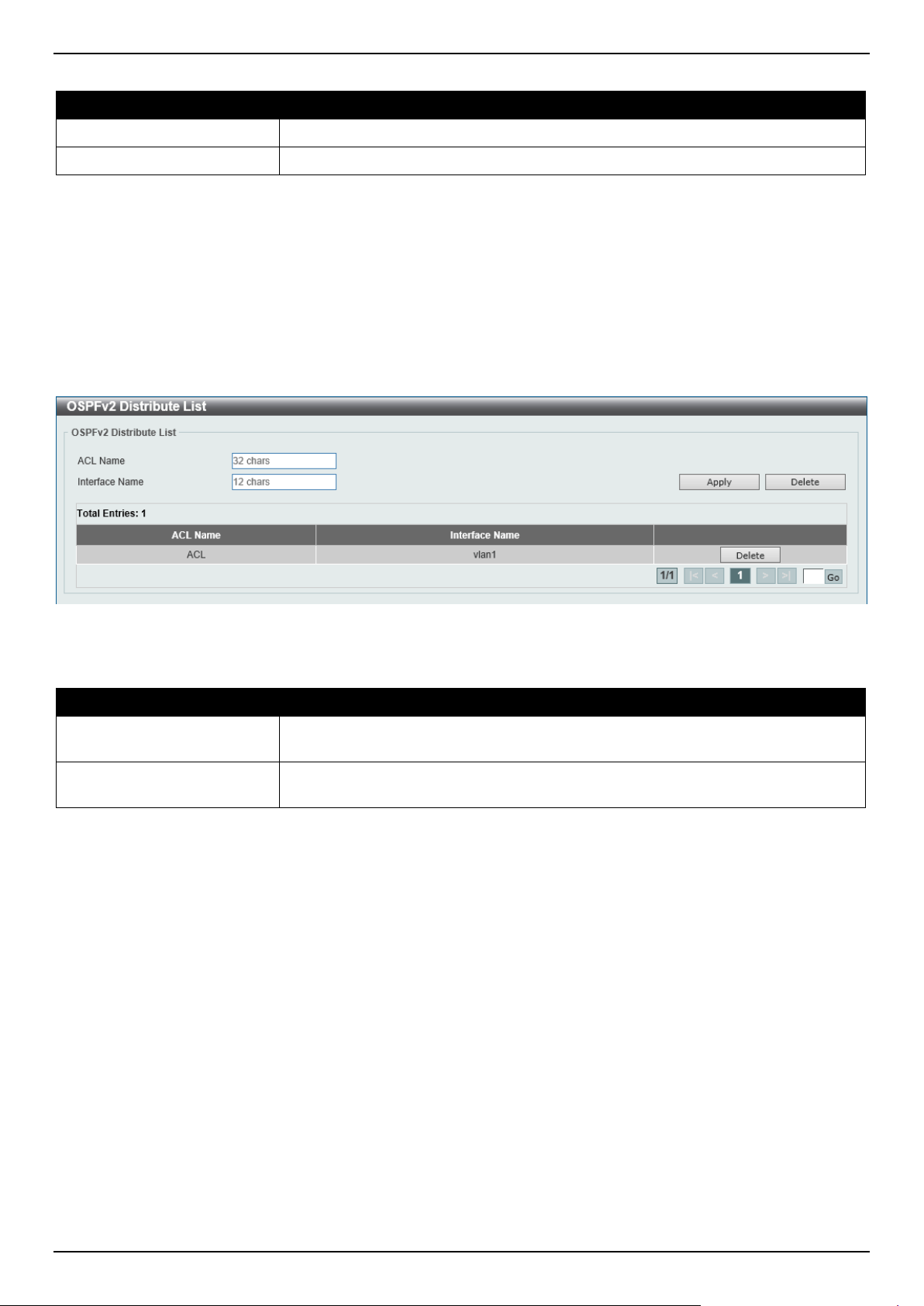
DGS-1520 Series Gigabit Ethernet Smart Managed Switch Web UI Reference Guide
250
The fields that can be configured are described below:
Parameter Description
RFC 1583 Compatible
Select to enable or disable the implementation of RFC 1583 here.
RFC 3509 Compatible
Select to enable or disable the implementation of RFC 3509 here.
Click the Apply button to accept the changes made.
Click the OK button to accept the changes made.
OSPFv2 Distribute List
This window is used the view and configure the OSPFv2 Distribute List settings.
To view the following window, click L3 Features > OSPF > OSPFv2 > OSPFv2 Distribute List, as shown below:
Figure 6-39 OSPFv2 Distribute List Window
The fields that can be configured are described below:
Parameter Description
ACL Name
Enter the access list name that will be used here. This name can be up to 32
characters long.
Interface Name
Enter the interface name that will be used here. This name can be up to 12
characters long.
Click the Apply button to accept the changes made.
Click the Delete button to delete the specified entry.
Enter a page number and click the Go button to navigate to a specific page when multiple pages exist.
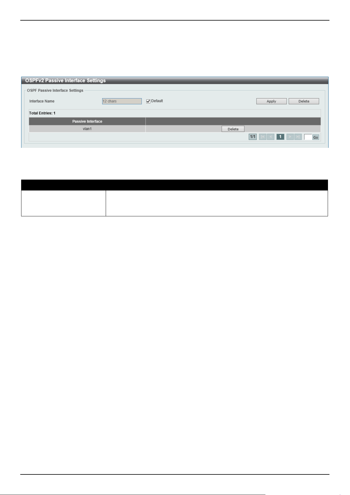
DGS-1520 Series Gigabit Ethernet Smart Managed Switch Web UI Reference Guide
251
OSPFv2 Passive Interface Settings
This window is used to display and configure the OSPFv2 passive interface settings.
To view the following window, click L3 Features > OSPF > OSPFv2 > OSPFv2 Passive Interface Settings, as
shown below:
Figure 6-40 OSPFv2 Passive Interface Settings Window
The fields that can be configured are described below:
Parameter Description
Interface Name
Enter the interface name that will be used here. This name can be up to 12
characters long.
Select the Default option to use all available interfaces here.
Click the Apply button to accept the changes made.
Click the Delete button to delete the specified entry.
Enter a page number and click the Go button to navigate to a specific page when multiple pages exist.
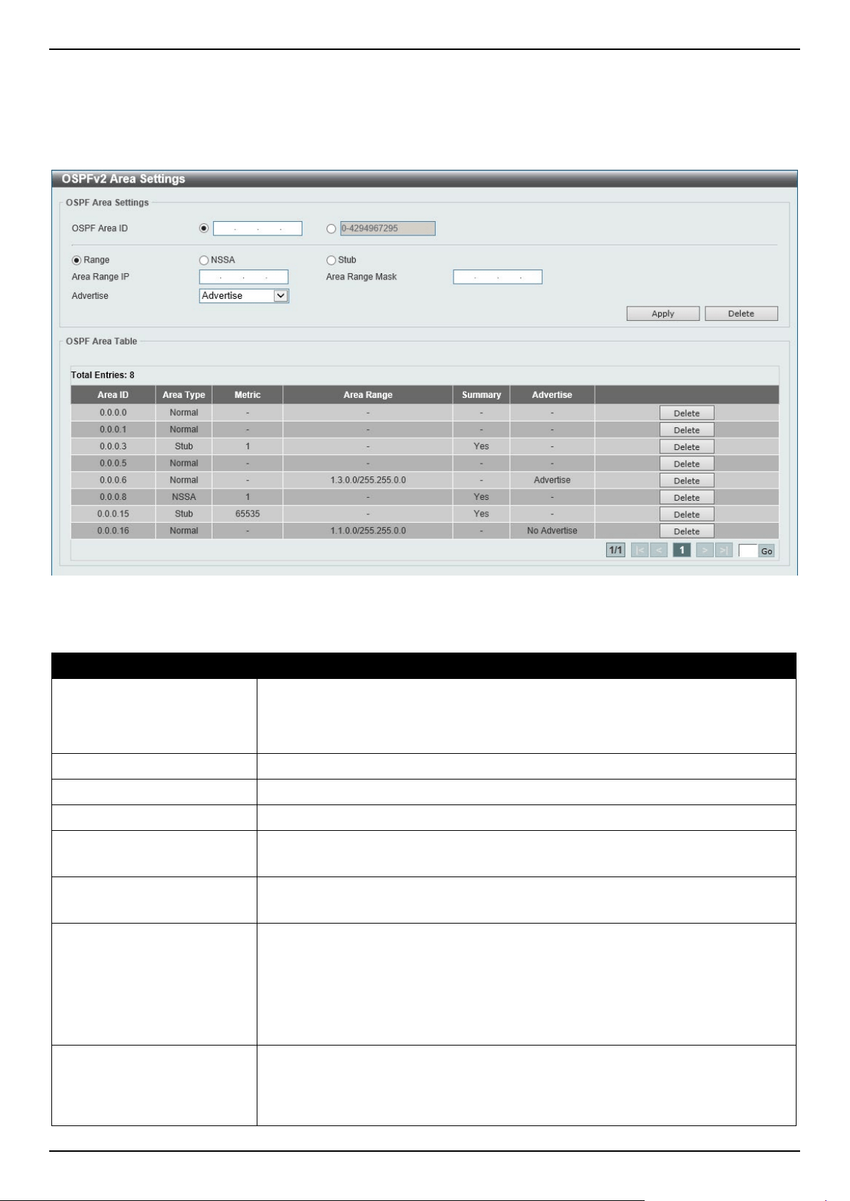
DGS-1520 Series Gigabit Ethernet Smart Managed Switch Web UI Reference Guide
252
OSPFv2 Area Settings
This window is used to display and configure the OSPFv2 area settings.
To view the following window, click L3 Features > OSPF > OSPFv2 > OSPFv2 Area Settings, as shown below:
Figure 6-41 OSPFv2 Area Settings Window
The fields that can be configured in OSPF Area Settings are described below:
Parameter Description
OSPF Area ID
Select and enter the OSPFv2 area ID here. This can be specified in the IP address
format or in the decimal value format. The decimal range is from 0 to 4294967295.
The area will be created on an interface if the subnet configured on the interface
falls within the network range specified here.
Range
Select this option to summarize OSPF routes at an Area Border Router (ABR).
NSSA
Select this option to assign the OSPF area as a Not-So-Stubby Area (NSSA) area.
Stub
Select this option to specify an OSPF area as a Stub Area.
Area Range IP
Enter the OSPF area range IP address here.
This parameter is available when Range is selected.
Area Range Mask
Enter the OSPF area range subnet mask here.
This parameter is available when Range is selected.
Advertise
Select the advertise option here. Options to choose from are:
• Advertise - Specifies to advertise a Type-3 summary Link-State
Advertisement (LSA) for the specified range of addresses.
• No-Advertise - Specifies to suppress the advertising of Type-3 summary
LSAs. Component routes are still hidden behind it.
This parameter is available when Range is selected.
Default Cost
Enter the default cost value here. This is the cost associated with the Type-3
default route that will be injected into the stub area and not-so-stubby area. The
range is from 0 to 65535.
• Default - Select this option to use the default cost value.
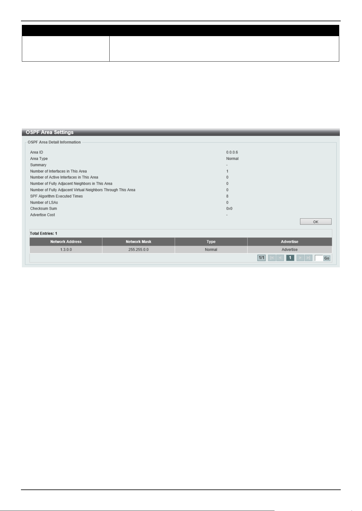
DGS-1520 Series Gigabit Ethernet Smart Managed Switch Web UI Reference Guide
253
Parameter Description
• No-Summary - Select this option not to inject summary routes into this
area.
This parameter is available when NSSA or Stub is selected.
Click the Apply button to accept the changes made.
Click the Delete button to delete an entry based on the information entered.
In the table, click the Delete button to remove the specific entry.
Double-click on the entry in the table to view detailed information about the entry.
After double-clicking on an entry in the table, the following page will appear.
Figure 6-42 OSPF Area Detail Information Window
Click the OK button to close the window.
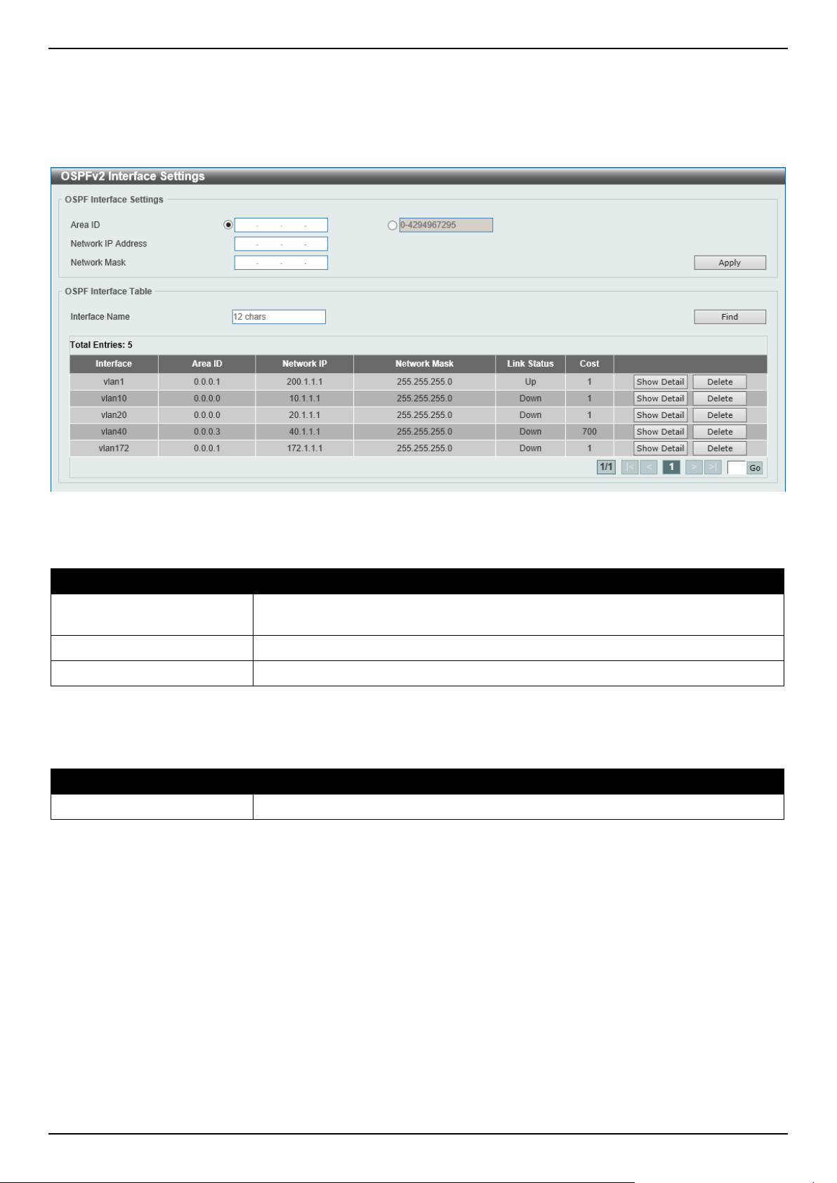
DGS-1520 Series Gigabit Ethernet Smart Managed Switch Web UI Reference Guide
254
OSPFv2 Interface Settings
This window is used to display and configure the OSPFv2 interface settings.
To view the following window, click L3 Features > OSPF > OSPFv2 > OSPFv2 Interface Settings, as shown below:
Figure 6-43 OSPFv2 Interface Settings Window
The fields that can be configured in OSPF Interface Settings are described below:
Parameter Description
Area ID
Select and enter the OSPFv2 area ID here. This can be specified in the IP address
format or in the decimal value format. The decimal range is from 0 to 4294967295.
Network IP Address
Enter the network IPv4 address here.
Network Mask
Enter the network IPv4 subnet mask here.
Click the Apply button to accept the changes made.
The fields that can be configured in OSPF Interface Table are described below:
Parameter Description
Interface Name
Enter the name of the interface to be displayed here.
Click the Find button to locate a specific entry based on the information entered.
Click the Show Detail button to view detailed information about the entry.
Click the Delete button to delete the specified entry.
Enter a page number and click the Go button to navigate to a specific page when multiple pages exist.
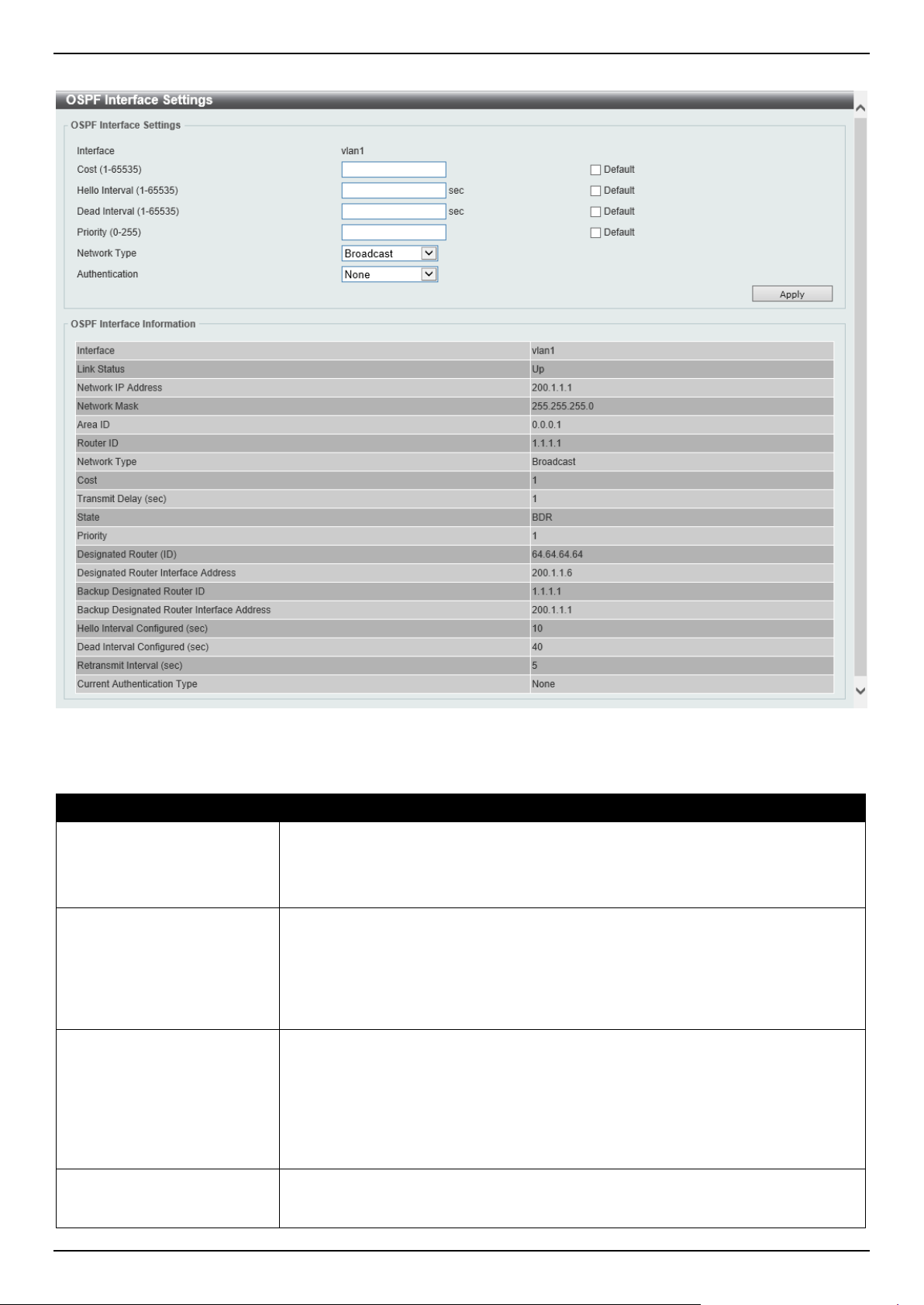
DGS-1520 Series Gigabit Ethernet Smart Managed Switch Web UI Reference Guide
255
After clicking the Show Detail button, the following page will appear.
Figure 6-44 OSPFv2 Interface Settings (Show Detail) Window
The fields that can be configured are described below:
Parameter Description
Cost
Enter the cost value here. The range is from 1 to 65535. The interface cost reflects
the overhead for sending the packet across the interface. This cost is advertised
as the link cost in the router link advertisement. By default, this value is 1.
Select the Default option to use the default value.
Hello Interval
Enter the Hello Interval time value here. The range is from 1 to 65535 seconds.
The Hello Interval is advertised in the hello packets. Configure the same hello-
interval for all routers on a specific network. A shorter Hello Interval ensures faster
detection of topological changes but generates more routing traffic and might
cause routing instability. By default, this value is 10 seconds.
Select the Default option to use the default value.
Dead Interval
Enter the Dead Interval time value here. The range is from 1 to 65535 seconds.
The Dead Interval is the amount of time that the router waits to receive an OSPF
hello packet from the neighbor before declaring the neighbor down. This value is
advertised in the router's hello packets. It must be the same for all routers on a
specific network. A smaller dead interval will ensure faster topology change
detection but might cause routing instability. By default, this value is 40 seconds.
Select the Default option to use the default value.
Priority
Enter the priority value here. The range is from 0 to 255. The OSPF router will
determine a Designated Router (DR) for the multi-access network. This sets the
priority used to determine the OSPF DR for a network. If two routers attempt to

DGS-1520 Series Gigabit Ethernet Smart Managed Switch Web UI Reference Guide
256
Parameter Description
become the DR, the router with the higher router priority will be elected the DR. If
the routers have the same priority, the router with the higher router ID takes
precedence. Only routers with non-zero router priority values are eligible to
become the DR or Backup Designated Router (BDR). By default, this value is 1.
Select the Default option to use the default value.
Network Type
Select the OSPF network type here. Options to choose from are:
• Broadcast - Specifies the network type as broadcast. On a broadcast
network, only the designated router and backup designated router become
adjacent neighbors of all other routers attached.
• Point-to-Point - Specifies the network type as point-to-point. On point-to-
point network, only two routers become adjacent if they can communicate.
Authentication
Select the authentication type that will be used here. Options to choose from are
None, Simple Password, and MD5.
Password After selecting the Simple Password option, enter the simple password here. This
password can be up to 8 characters long. The syntax is general string that does
not allow spaces.
This creates a password (key) that is inserted into the OSPF header when the
router originates routing protocol packets. Assign a separate password to each
network for different interfaces. Routers on the same network must use the same
password to be able to exchange OSPF routing data. Configure the routers in the
same routing domain with the same password.
MD5 Key ID After selecting the MD5 option, enter the MD5 key ID for the password here. The
range is from 1 to 255.
MD5 After selecting the MD5 option, enter the MD5 key here. This key must be 16
characters long. The syntax is an alphanumeric string that does not allow spaces.
In the MD5 mode, the OSPF message sender will compute a message digest
based on the message digest key for the TX message. The message digest and
the key ID will be encoded in the packet. The receiver of the packet will verify the
digest in the message against the digest computed based on the locally defined
message digest key corresponding to the same key ID.
The same key ID on the neighboring router should be defined with the same key
string.
All the neighboring routers on the same interface must use the same key to
exchange the OSPF packet with each other. Normally, all neighboring routers on
the interface use the same key.
With the MD5 digest mode, the user can roll over to a new key without disrupting
the current message exchange using the new key. Supposing that a router is
currently using an old key to exchange OSPF packets with the neighbor router, as
the user configures a new key, the router will start the roll over process by sending
duplicated packets for both of the old and the new key. The router will stop sending
duplicated packets until it finds that all routers on the network have learned the
new key. After the rollover process completed, the user should delete the old key
to prevent the router from communicating with the router using the old key.
Click the Apply button to accept the changes made.
OSPFv2 Redistribute Settings
This window is used to display and configure the OSPFv2 redistribution settings. External routes can be redistributed
to normal areas as Type-5 external routes and redistributed to NSSA stub areas as Type-7 external routes by the
ASBR. If the redistributed external route is of Type-1, the metric represents the internal metric. If the redistributed
external route is of Type-2, the metric represents the external metric. An internal metric will consider the cost of the
route from itself to the redistributing router plus the advertised cost to reach the destination. An external metric only
considers the advertised metric to reach the destination. If no metric value is specified by the default metric, routes
redistributed from other protocols will get a metric value of 20.
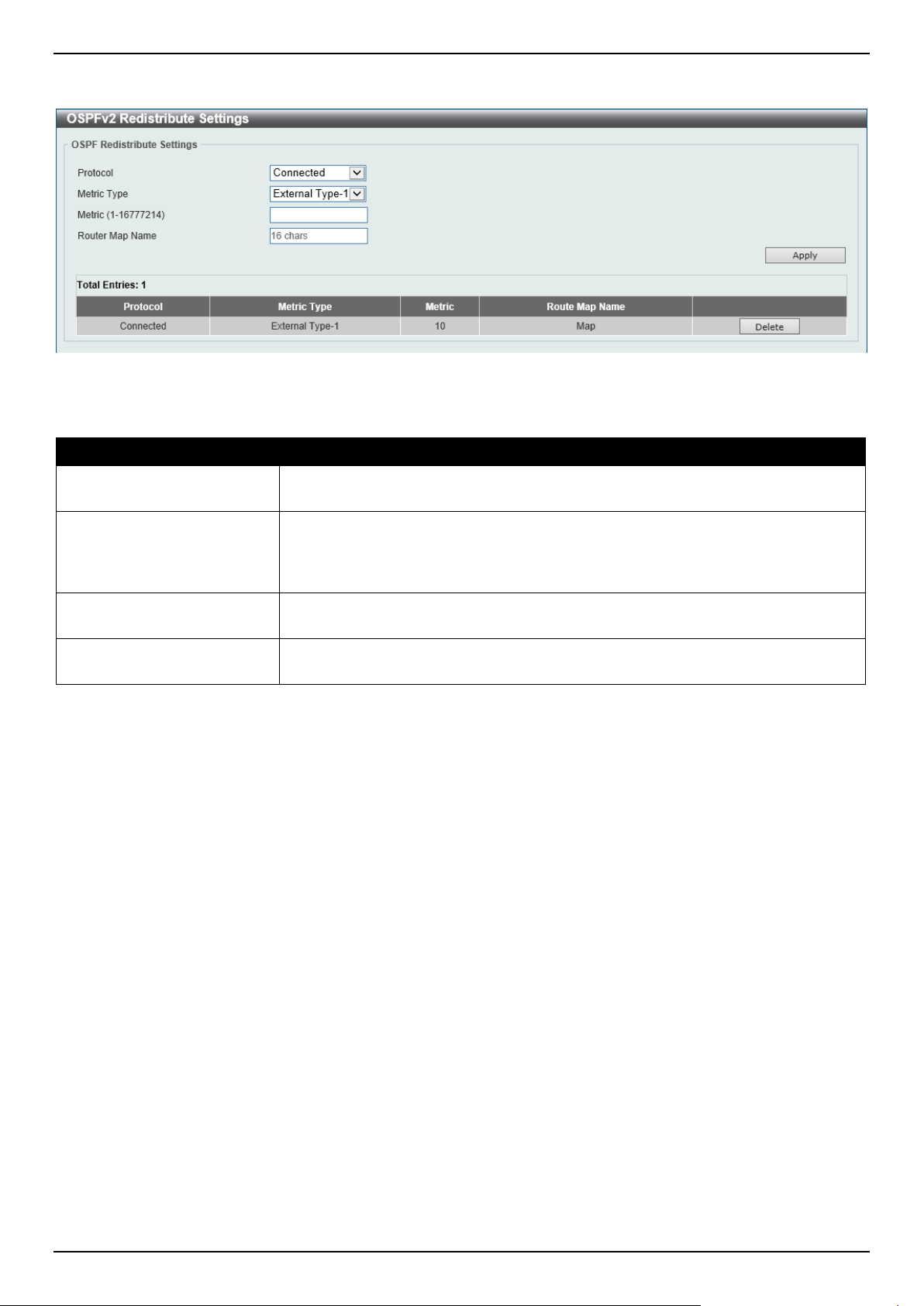
DGS-1520 Series Gigabit Ethernet Smart Managed Switch Web UI Reference Guide
257
To view the following window, click L3 Features > OSPF > OSPFv2 > OSPFv2 Redistribute Settings, as shown
below:
Figure 6-45 OSPFv2 Redistribute Settings Window
The fields that can be configured are described below:
Parameter Description
Protocol
Select the source protocol that will be redistributed here. Options to choose from
are Connected, Static, and RIP.
Metric Type Select the metric type here. Options to choose from are External Type-1 and
External Type-2. This specifies the external link type of the route being
redistributed into the OSPF routing domain. If a metric type is not specified, the
Switch will adopt a Type-2 external route.
Metric
Enter the metric value for the redistributed routes here. The range is from 1 to
16777214.
Router Map Name
Enter the route map name here that filters the imported routes from this source
routing protocol. If not specified, all routes are redistributed.
Click the Apply button to accept the changes made.
Click the Delete button to delete the specified entry.

DGS-1520 Series Gigabit Ethernet Smart Managed Switch Web UI Reference Guide
258
OSPFv2 Virtual Link Settings
This window is used to display and configure OSPFv2 virtual link settings. If a non-zero area is not physically
connected to the zero area, it must be connected to the zero area via a virtual link. The virtual link is a point-to-point
link. The router will send the OSPF message to the neighbor router as unicast IP packet.
To view the following window, click L3 Features > OSPF > OSPFv2 > OSPFv2 Virtual Link Settings, as shown
below:
Figure 6-46 OSPFv2 Virtual Link Settings Window
The fields that can be configured in OSPF Virtual Link are described below:
Parameter Description
Area ID
Select and enter the OSPFv2 area ID here. This can be specified in the IP address
format or in the decimal value format. The decimal range is from 0 to 4294967295.
This area will be used to establish the virtual link.
Router ID
Enter the router ID of the virtual link neighbor here.
Hello Interval
Enter the hello packet interval that the router sends on the virtual link here. The
range is from 1 and 65535 seconds. By default, this value is 10 seconds.
Select the Default option to use the default value.
Dead Interval
Enter the Dead Interval time after which a neighbor is regarded as offline if no hello
packets are received within that time frame here. The range is from 1 and 65535
seconds. By default, this value is 40 seconds.
Select the Default option to use the default value.
Authentication Select the authentication type used here. Options to choose from are None,
Simple Password, and MD5.
Password After selecting the Simple Password authentication type, enter the password to
be used here. This password can be up to 8 characters long.
MD5 Key ID After selecting the MD5 authentication type, enter the MD5 authentication key ID
here. The range is from 1 to 255.
MD5 Key After selecting the MD5 authentication type, enter the MD5 authentication key
here. This key can be up to 16 characters long.
Click the Apply button to accept the changes made.
Click the Delete button to delete the specified entry.
Double-click on the entry in the table to view detailed information about the entry.
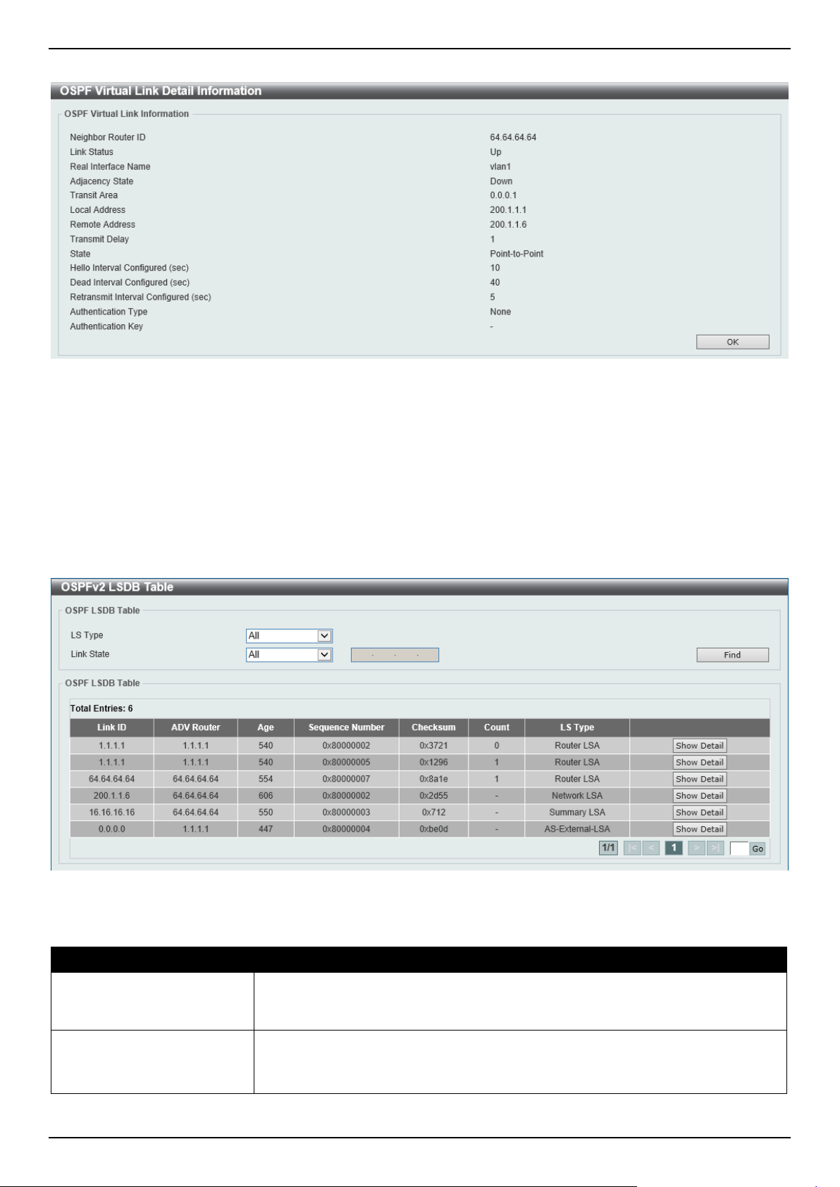
DGS-1520 Series Gigabit Ethernet Smart Managed Switch Web UI Reference Guide
259
After double-clicking on an entry in the table, the following page will appear.
Figure 6-47 OSPF Virtual Link Information Window
Click the OK button to return to the previous window.
OSPFv2 LSDB Table
This window is used to display the OSPFv2 LSDB table and information.
To view the following window, click L3 Features > OSPF > OSPFv2 > OSPFv2 LSDB Table, as shown below:
Figure 6-48 OSPFv2 LSDB Table Window
The fields that can be configured are described below:
Parameter Description
LS Type
Select the LSDB type of information that will be displayed here. Options to choose
from are All, Router, Network, Summary, ASBR Summary, External, Stub, and
NSSA External.
Link State
Select the link-state information that will be displayed here. Options to choose from
are:
• All - Specifies to display all OSPFv2 link-state information.
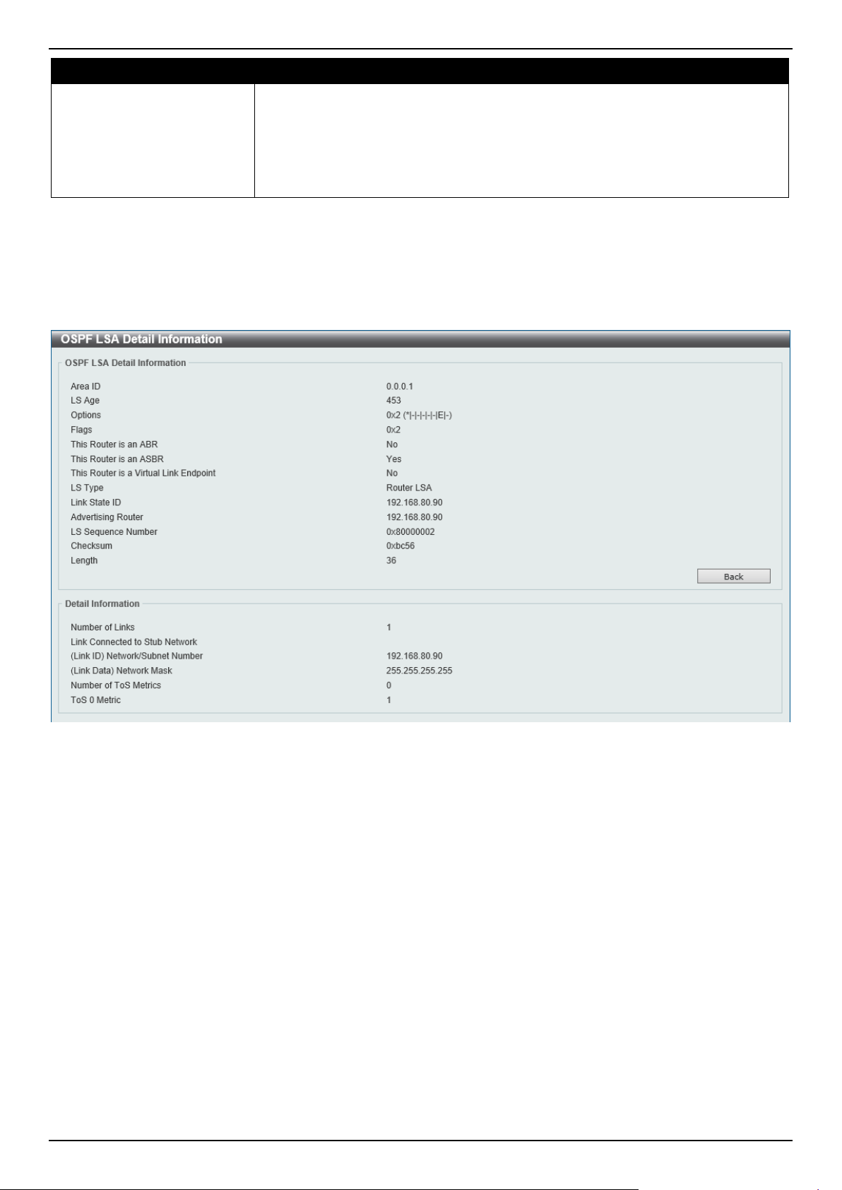
DGS-1520 Series Gigabit Ethernet Smart Managed Switch Web UI Reference Guide
260
Parameter Description
• Link State ID - Specifies to display information associated with the link-state
ID. Enter the link state ID in the space provided here.
• Self-Originate - Specifies to display LSAs generated by the local router.
• Adv Router - Specifies to display all of the LSAs generated by the
advertising router. Enter the advertising router ID in the space provided
here.
Click the Find button to locate a specific entry based on the information entered.
Click the Show Detail button to view detailed information about the specific entry.
Enter a page number and click the Go button to navigate to a specific page when multiple pages exist.
After clicking the Show Detail button, the following page will appear.
Figure 6-49 OSPFv2 LSDB Table (Show Detail) Window
Click the Back button to return to the previous window.
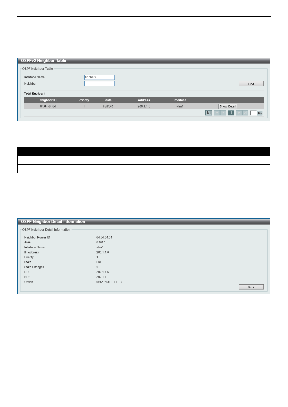
DGS-1520 Series Gigabit Ethernet Smart Managed Switch Web UI Reference Guide
261
OSPFv2 Neighbor Table
This window is used to display information on OSPF neighbors.
To view the following window, click L3 Features > OSPF > OSPFv2 > OSPFv2 Neighbor Table, as shown below:
Figure 6-50 OSPFv2 Neighbor Table Window
The fields that can be configured are described below:
Parameter Description
Interface Name
Enter the name of the interface that will be used in the results here.
Neighbor
Enter the neighbor ID here.
Click the Find button to locate a specific entry based on the information entered.
Click the Show Detail button to view detailed information for the specified entry.
Enter a page number and click the Go button to navigate to a specific page when multiple pages exist.
After clicking the Show Detail button, the following page will appear.
Figure 6-51 OSPFv2 Neighbor Table (Show Detail) Window
Click the Back button to return to the previous window.
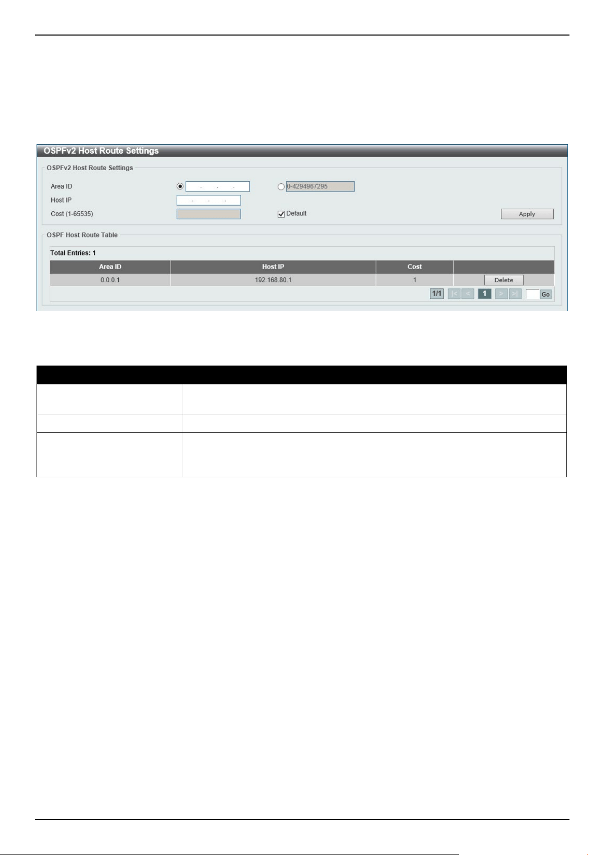
DGS-1520 Series Gigabit Ethernet Smart Managed Switch Web UI Reference Guide
262
OSPFv2 Host Route Settings
This window is used to display and configure the OSPFv2 host route settings. The router will advertise specific host
routes as router LSAs for a stub link.
To view the following window, click L3 Features > OSPF > OSPFv2 > OSPFv2 Host Route Settings, as shown
below:
Figure 6-52 OSPFv2 Host Route Settings Window
The fields that can be configured in OSPFv2 Host Route Settings are described below:
Parameter Description
Area ID
Select and enter the OSPFv2 area ID here. This can be specified in the IP address
format or in the decimal value format. The decimal range is from 0 to 4294967295.
Host IP
Enter the host IPv4 address here.
Cost
Enter the cost value for the stub entry here. The range is from 1 to 65535. By
default, this value is 1.
Select the Default option to use the default value.
Click the Apply button to accept the changes made.
Click the Delete button to delete the specified entry.
Enter a page number and click the Go button to navigate to a specific page when multiple pages exist.
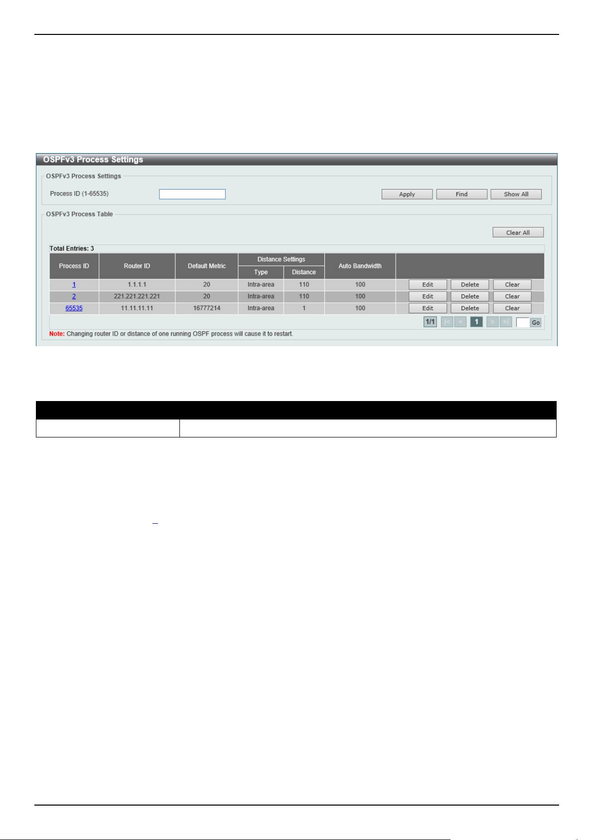
DGS-1520 Series Gigabit Ethernet Smart Managed Switch Web UI Reference Guide
263
OSPFv3
OSPFv3 Process Settings
This window is used to display and configure OSPFv3 process settings.
To view the following window, click L3 Features > OSPF > OSPFv3 > OSPFv3 Process Settings, as shown below:
Figure 6-53 OSPFv3 Process Settings Window
The fields that can be configured are described below:
Parameter Description
Process ID
Enter the OSPFv3 process ID here. The range is from 1 to 65535.
Click the Apply button to accept the changes made.
Click the Find button to locate a specific entry based on the information entered.
Click the Show All button to display all the entries.
Click the Clear All button to restart all OSPFv3 processes.
Click the Process ID link (1) to access and configure the specified OSPFv3 process.
Click the Edit button to modify the specified entry.
Click the Delete button to delete the specified entry.
Click the Clear button to restart the specified OSPFv3 process.
Enter a page number and click the Go button to navigate to a specific page when multiple pages exist.
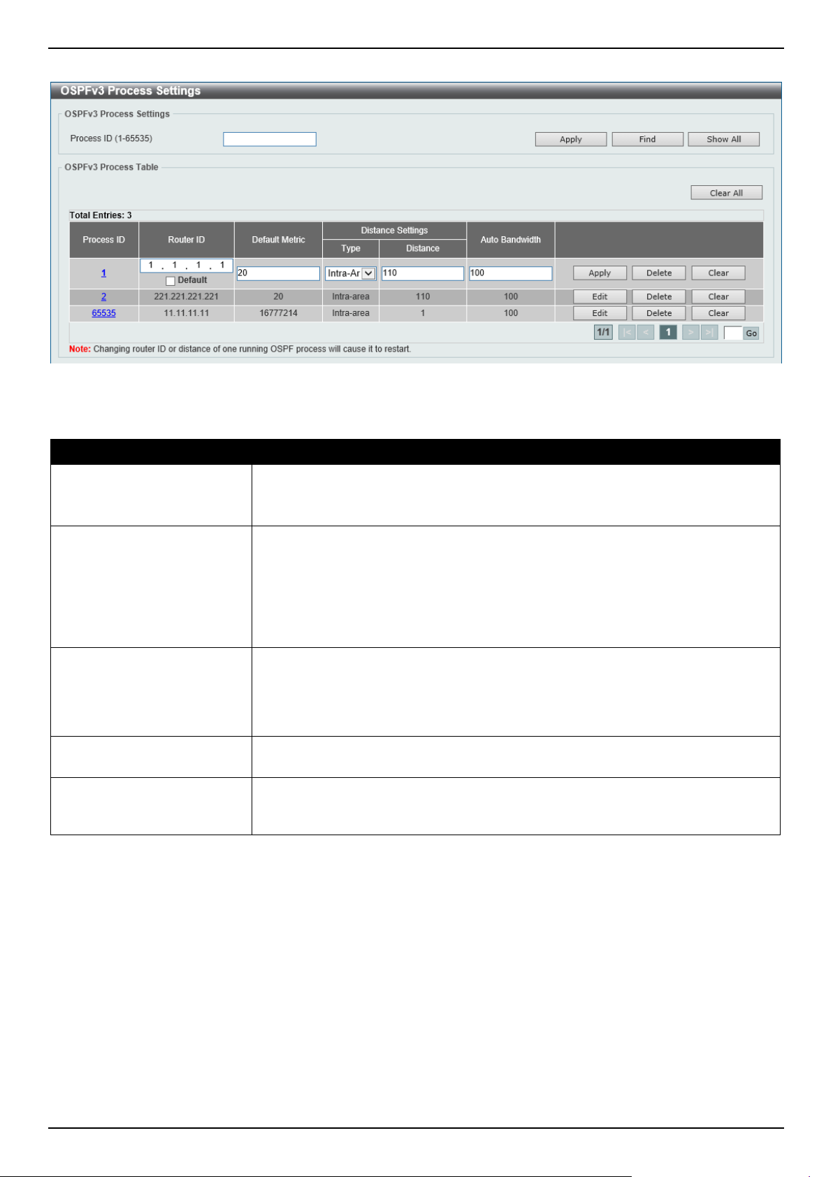
DGS-1520 Series Gigabit Ethernet Smart Managed Switch Web UI Reference Guide
264
After clicking the Edit button, the following page will appear.
Figure 6-54 OSPFv3 Process Settings (Edit) Window
The fields that can be configured are described below:
Parameter Description
Router ID
Enter the router ID for the OSPF process here. By default, the router ID is
automatically selected.
Select the Default option to use the default router ID.
Default Metric
Enter the default metric value for the OSPF process here. The range is from 1 to
16777214. By default, this value is 20. This value is used in conjunction with the
OSPFv3 redistribution feature to enable the current routing protocol to use the
same metric value for all redistributed routes. A default metric helps solve the
problem of redistributing routes with incompatible metrics. Whenever the metrics
don't convert directly, using a default metric provides a reasonable substitute and
enables the redistribution to proceed.
Type
Select the distance type here. Options to choose from are:
• Intra-Area - Specifies the distance for OSPF intra-area routes.
• Inter-Area - Specifies the distance for OSPF inter-area routes.
• External - Specifies the distance for OSPF external routes.
Distance
Enter the distance value for the OSPF process here. The range is from 1 to 254.
By default, this value is 110 for all OSPF routes.
Auto Bandwidth
Enter the auto-bandwidth value here. This feature is used to control the reference
value IPv6 OSPF uses when calculating metrics for interfaces. The range is from 1
to 4294967.
Click the Apply button to accept the changes made.
Click the Delete button to delete the specified entry.
Enter a page number and click the Go button to navigate to a specific page when multiple pages exist.
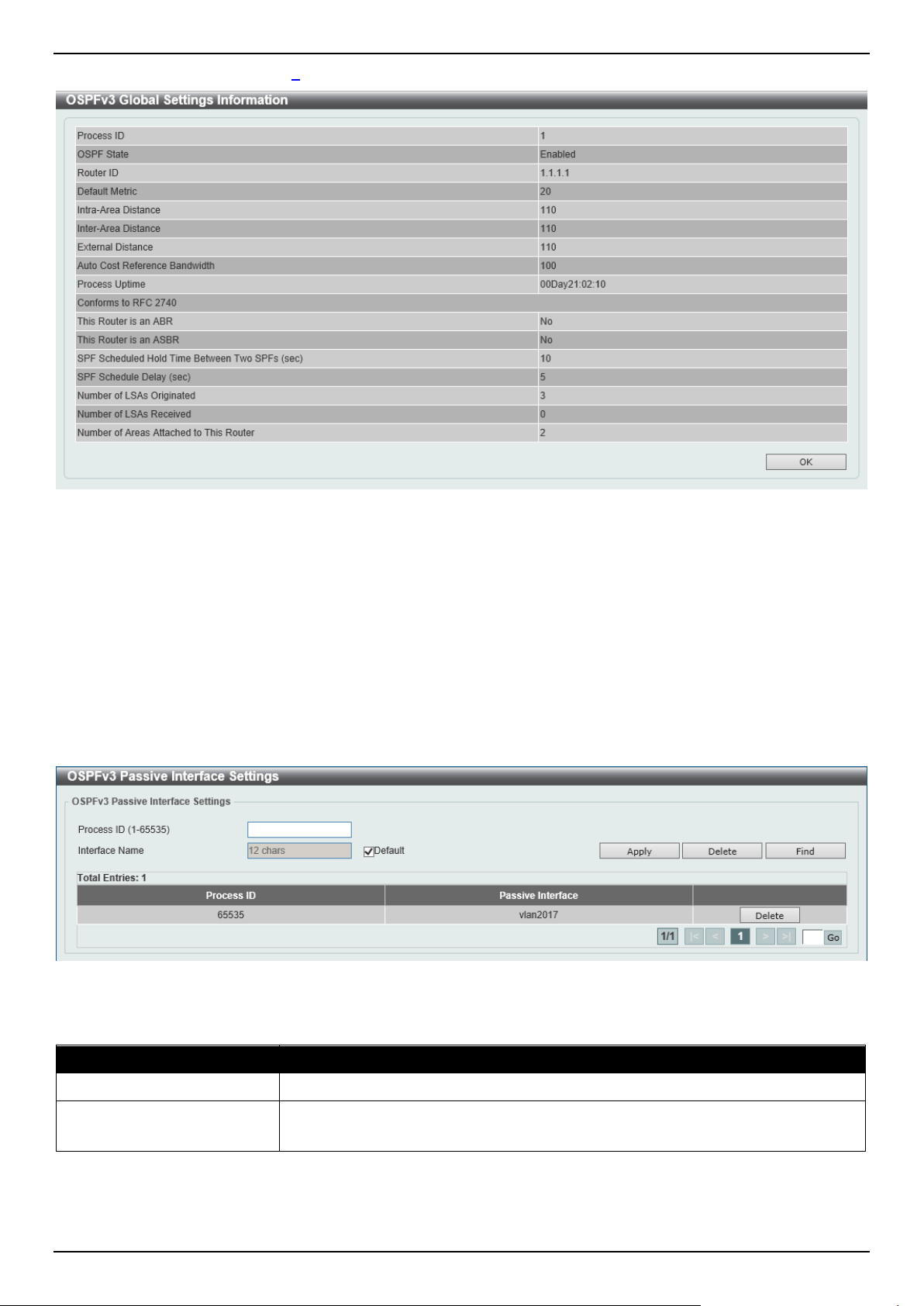
DGS-1520 Series Gigabit Ethernet Smart Managed Switch Web UI Reference Guide
265
After clicking the Process ID link (1) in the table, the following page will appear.
Figure 6-55 OSPFv3 Process Settings (Process ID) Window
Click the OK button to close the window and return to the previous window.
OSPFv3 Passive Interface Settings
This window is used to display and configure the OSPFv3 passive interface settings. If an interface is passive, the
OSPF routing update packets are not sent or received through the specified interface.
To view the following window, click L3 Features > OSPF > OSPFv3 > OSPFv3 Passive Interface Settings, as
shown below:
Figure 6-56 OSPFv3 Passive Interface Settings Window
The fields that can be configured are described below:
Parameter Description
Process ID
Enter the OSPFv3 process ID here. The range is from 1 to 65535.
Interface Name
Enter the passive interface name here. This name can be up to 12 characters long.
Select the Default option specify all the interfaces as passive interfaces.
Click the Apply button to accept the changes made.
Click the Delete button to delete the specified entry.
Click the Find button to locate a specific entry based on the information entered.
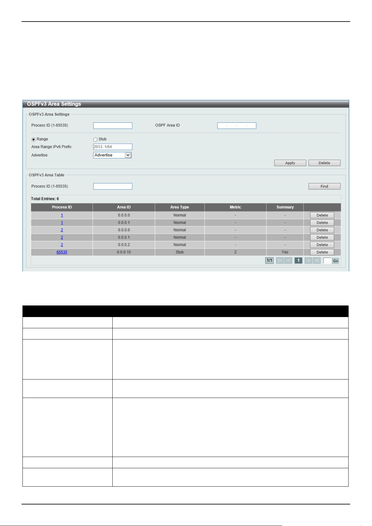
DGS-1520 Series Gigabit Ethernet Smart Managed Switch Web UI Reference Guide
266
Enter a page number and click the Go button to navigate to a specific page when multiple pages exist.
OSPFv3 Area Settings
This window is used to display and configure the OSPFv3 area settings.
To view the following window, click L3 Features > OSPF > OSPFv3 > OSPFv3 Area Settings, as shown below:
Figure 6-57 OSPFv3 Area Settings Window
The fields that can be configured in OSPFv3 Area Settings are described below:
Parameter Description
Process ID
Enter the process ID of the OSPF area used here. The range is from 1 to 65535.
OSPF Area ID
Enter the OSPF area ID used here. It can be specified as an IPv4 address.
Range
Select this option to consolidate and summarize routes at an area boundary. This
feature is used only with ABRs. It is used to consolidate or summarize routes for
an area. The result is that a single summary route is advertised to other areas by
the ABR. Routing information is condensed at area boundaries. External to the
area, a single route is advertised for each address range.
Area Range IPv6 Prefix After selecting the Range option, enter the OSPF area range IPv6 prefix and prefix
length here.
Advertise After selecting the Range option, select the advertise option here. Options to
choose from are:
• Advertise - Specifies to advertise and generate an inter-area prefix LSA for
the specified address range.
• No Advertise - Specifies to set the status to Do-Not-Advertise for the
specified address range. The inter-area prefix LSA is suppressed, and the
component networks remain hidden from other networks.
Stub
Select this option to define an area as a Stub area.
Metric After selecting the Stub option, enter the stub area metric value here. The range is
from 0 to 65535.
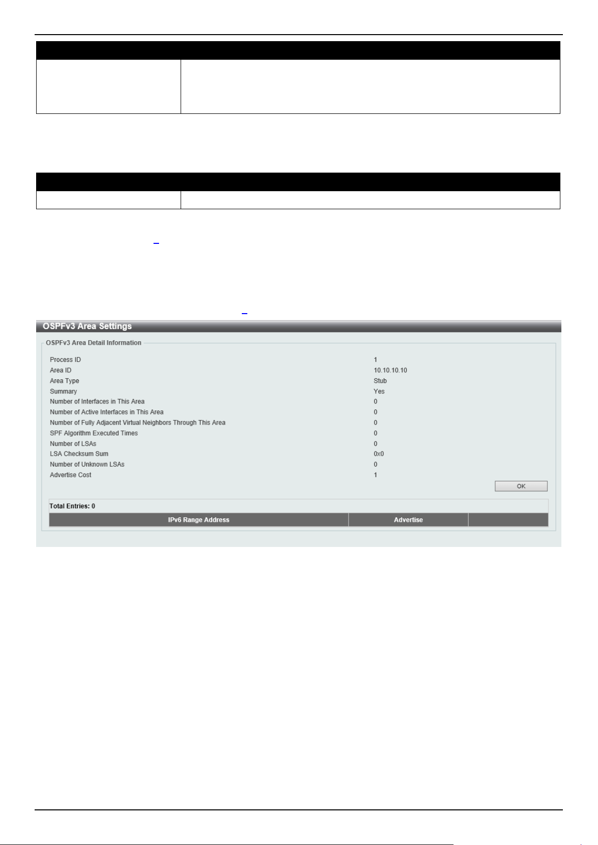
DGS-1520 Series Gigabit Ethernet Smart Managed Switch Web UI Reference Guide
267
Parameter Description
• Default Cost - Select this option use the default metric value for this area,
which is 1. Select the Default option to use the default cost value.
• No Summary - Select this option to prevent an ABR from sending inter-area
prefix LSAs into the stub area.
Click the Apply button to accept the changes made.
The fields that can be configured in OSPFv3 Area Table are described below:
Parameter Description
Process ID
Enter the process ID of the OSPF area used here. The range is from 1 to 65535.
Click the Find button to locate a specific entry based on the information entered.
Click the Process ID link (1) to access and configure the specified OSPFv3 area.
Click the Delete button to delete the specified entry.
Enter a page number and click the Go button to navigate to a specific page when multiple pages exist.
After clicking a Stub area the Process ID link (1) in the table, the following page will appear.
Figure 6-58 OSPFv3 Area Settings (Process ID, Stub) Window
Click the OK button to close the window and return to the previous window.
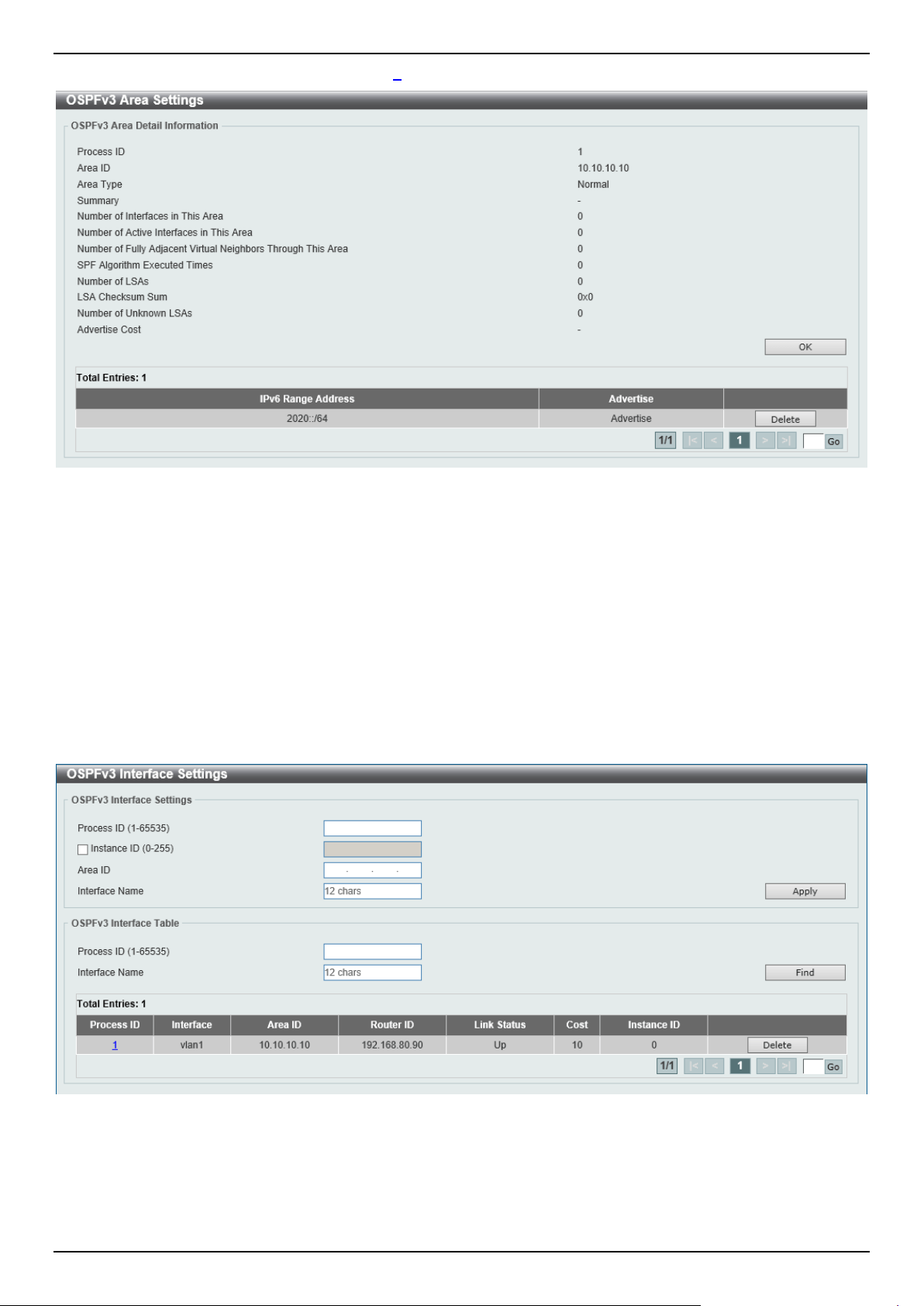
DGS-1520 Series Gigabit Ethernet Smart Managed Switch Web UI Reference Guide
268
After clicking a Normal area the Process ID link (1) in the table, the following page will appear.
Figure 6-59 OSPFv3 Area Settings (Process ID, Normal) Window
Click the OK button to close the window and return to the previous window.
Click the Delete button to delete the specified entry.
Enter a page number and click the Go button to navigate to a specific page when multiple pages exist.
OSPFv3 Interface Settings
This window is used to display and configure the OSPFv3 interface settings.
To view the following window, click L3 Features > OSPF > OSPFv3 > OSPFv3 Interface Settings, as shown below:
Figure 6-60 OSPFv3 Interface Settings Window

DGS-1520 Series Gigabit Ethernet Smart Managed Switch Web UI Reference Guide
269
The fields that can be configured in OSPFv3 Interface Settings are described below:
Parameter Description
Process ID
Enter the ID for an IPv6 OSPF routing process here. It is locally assigned and
should be unique for each IPv6 OSPF routing process on the router. The range is
from 1 to 65535.
Instance ID
Enter the instance identifier here. The range is from 0 to 255. By default, this value
is 0.
Area ID
Enter the identifier of the area here. It can be specified as an IPv4 address.
Interface Name
Enter the name of the VLAN interface here. This name can be up to 12 characters
long.
Click the Apply button to accept the changes made.
The fields that can be configured in OSPF Interface Table are described below:
Parameter Description
Process ID
Enter the ID for an IPv6 OSPF routing process here. The range is from 1 to 65535.
Interface Name
Enter the name of the interface here.
Click the Find button to locate a specific entry based on the information entered.
Click the Process ID link (1) to access and configure the specified OSPFv3 interface.
Click the Delete button to delete the specified entry.
Enter a page number and click the Go button to navigate to a specific page when multiple pages exist.
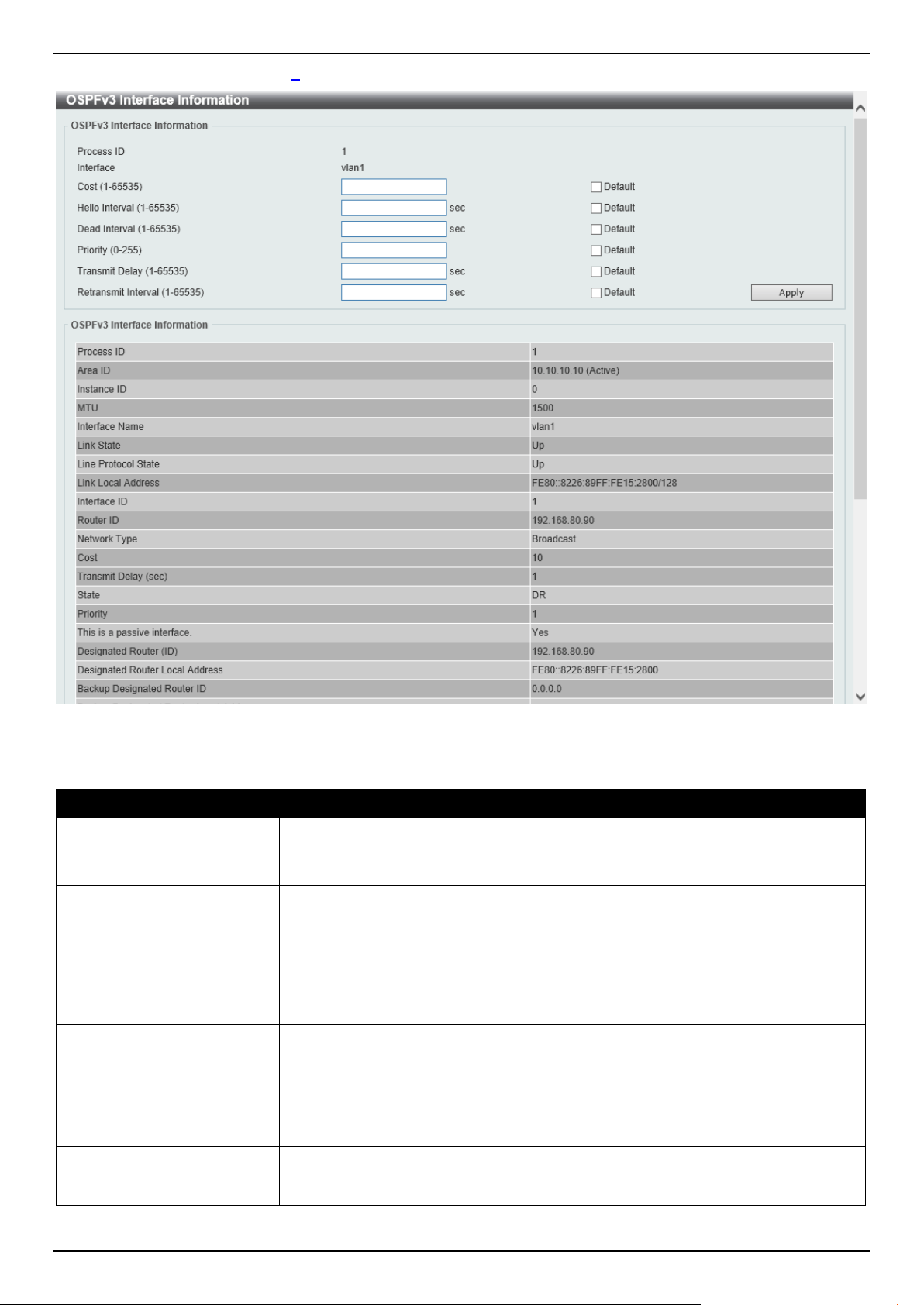
DGS-1520 Series Gigabit Ethernet Smart Managed Switch Web UI Reference Guide
270
After clicking the Process ID link (1) button, the following page will appear.
Figure 6-61 OSPFv3 Interface Settings (Process ID) Window
The fields that can be configured are described below:
Parameter Description
Cost
Enter cost value here. It is an integer value expressed as the link-state metric. The
range is from 1 to 65535.
Select the Default option to use the default value.
Hello Interval
Enter the Hello Interval value, between the hello packets that the router sends on
an interface here. This value is advertised in the hello packets. The shorter the
Hello Interval, the earlier topological changes will be detected, but more routing
traffic will ensue. This value must be the same for all routers and access servers
on a specific network. The range is from 1 to 65535 seconds. By default, this value
is 10 seconds.
Select the Default option to use the default value.
Dead Interval
Enter the Dead Interval value here, during which no packets are received and after
which a neighbor is regarded as offline. The interval is advertised in router hello
packets. This value must be the same for all routers and access servers on a
specific network. The range is from 1 to 65535 seconds. By default, this value is 40
seconds.
Select the Default option to use the default value.
Priority
Enter the priority value of the router here. The range is from 0 to 255. Set the
priority to help determine the OSPF Designated Router (DR) for a network. If two
routers attempt to become the DR, the router with the higher router priority
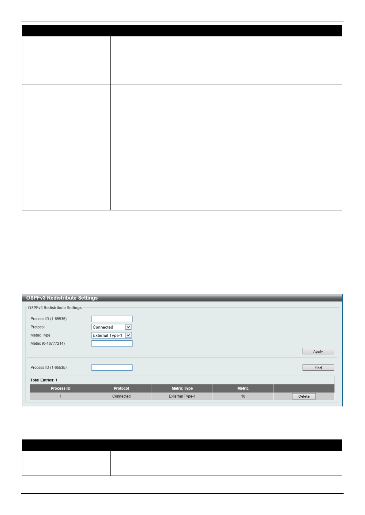
DGS-1520 Series Gigabit Ethernet Smart Managed Switch Web UI Reference Guide
271
Parameter Description
becomes the DR. If the router priority is the same for two routers, the router with
the higher router ID takes precedence.
Only routers with non-zero router priority values are eligible to become the
designated or backup designated router. Configure router priority for multi-access
networks (not point-to-point) only. By default, this value is 1.
Select the Default option to use the default value.
Transmit Delay
Enter the Transmit Delay value here. The range is from 1 to 65535 seconds. Link-
State Updates (LSUs) must have their ages incremented by the amount specified
in the seconds argument before transmission. The value assigned should take into
account the transmission and propagation delays for the interface.
If the delay is not added before transmission over a link, the time in which the LSA
propagates over the link is not considered. This setting has more significance on
very low speed links. By default, this value is 1.
Select the Default option to use the default value.
Retransmit Interval
Enter the Retransmit Interval value here. The range is from 1 to 65535 seconds.
After sending an LSA to a neighbor, the router keeps the LSA until it receives an
acknowledgement. If the router does not receive an acknowledgement during the
set time (the Retransmit Interval value), it retransmits the LSA. Set the
retransmission interval value conservatively to avoid unnecessary retransmission.
The interval should be greater than the expected round-trip delay between two
routers. By default, this value is 5 seconds.
Select the Default option to use the default value.
Click the Apply button to accept the changes made.
OSPFv3 Redistribute Settings
This window is used to display and configure the OSPFv3 redistribution settings.
To view the following window, click L3 Features > OSPF > OSPFv3 > OSPFv3 Redistribute Settings, as shown
below:
Figure 6-62 OSPFv3 Redistribute Settings Window
The fields that can be configured are described below:
Parameter Description
Process ID
Enter the ID for an IPv6 OSPF routing process here. It is locally assigned and
should be unique for each IPv6 OSPF routing process on the router. The range is
from 1 to 65535.
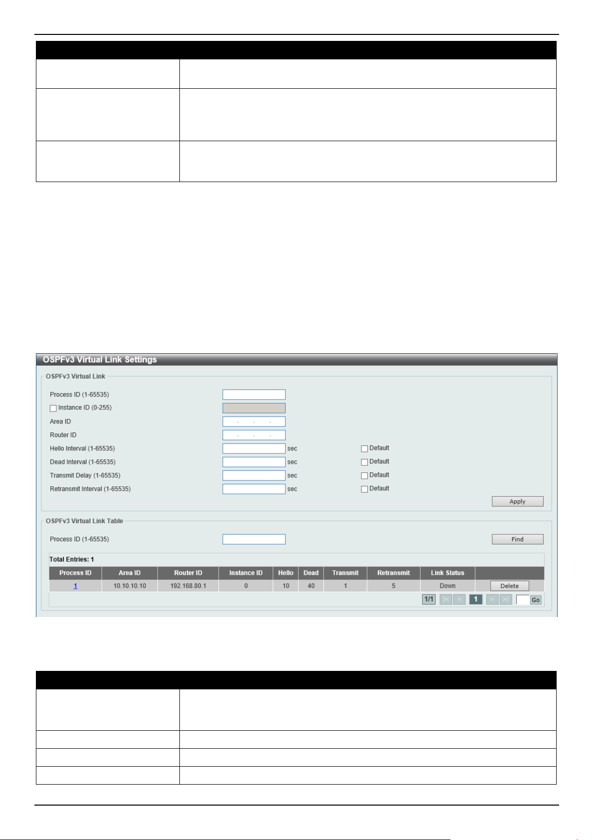
DGS-1520 Series Gigabit Ethernet Smart Managed Switch Web UI Reference Guide
272
Parameter Description
Protocol
Select the source protocol from which routes will be redistributed here. Options to
choose from are Connected, Static, and RIPng.
Metric Type
Select the external link type associated with the default route advertised into the
IPv6 OSPF routing domain here. Options to choose from are External Type-1 and
External Type-2. If a metric type is not specified, the Switch adopts a Type-2
external route. This is only for IPv6 OSPF.
Metric
Enter the metric value here. This value is used when redistributing other processes
to an IPv6 OSPF process. The range is from 0 to 16777214. By default, this value
is 20.
Click the Apply button to accept the changes made.
Click the Find button to locate a specific entry based on the information entered.
Click the Delete button to delete the specified entry.
OSPFv3 Virtual Link Settings
This window is used to display and configure the OSPFv3 virtual link settings.
To view the following window, click L3 Features > OSPF > OSPFv3 > OSPFv3 Virtual Link Settings, as shown
below:
Figure 6-63 OSPFv3 Virtual Link Settings Window
The fields that can be configured in OSPFv3 Virtual Link are described below:
Parameter Description
Process ID
Enter the ID for an IPv6 OSPF routing process here. It is locally assigned and
should be unique for each IPv6 OSPF routing process on the router. The range is
from 1 to 65535.
Instance ID
Select and enter the instance ID here. The range is from 0 to 255.
Area ID
Enter the OSPF area ID here. It can be specified as an IPv4 address.
Router ID
Enter the router ID here associated with the virtual link neighbor.
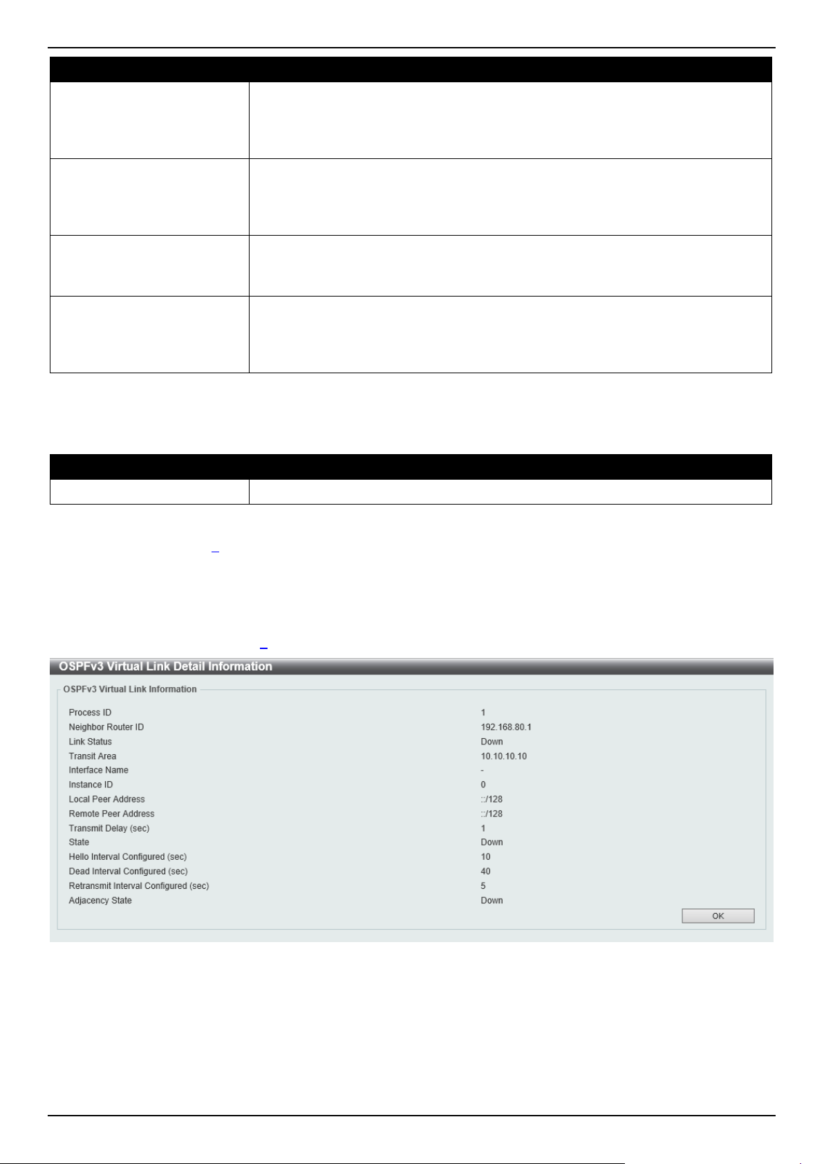
DGS-1520 Series Gigabit Ethernet Smart Managed Switch Web UI Reference Guide
273
Parameter Description
Hello Interval
Enter the Hello Interval value between the hello packets that the router sends on
an interface here. The range is from 1 to 65535 seconds. By default, this value is
10 seconds.
Select the Default option to use the default value.
Dead Interval
Enter the Dead Interval value, during which no packets are received and after
which a neighbor is regarded as offline, here. The range is from 1 to 65535
seconds. By default, this value is 40 second.
Select the Default option to use the default value.
Transmit Delay
Enter the transmit delay value here that the router uses to wait before it transmits a
packet. The range is from 1 to 65535 seconds. By default, this value is 1 second.
Select the Default option to use the default value.
Retransmit Interval
Enter the retransmit interval value here that the router uses to wait before it
retransmits a packet. The range is from 1 to 65535 seconds. By default, this value
is 5 seconds.
Select the Default option to use the default value.
Click the Apply button to accept the changes made.
The fields that can be configured in OSPF Virtual Link Table are described below:
Parameter Description
Process ID
Enter the ID for an IPv6 OSPF routing process here. The range is from 1 to 65535.
Click the Find button to locate a specific entry based on the information entered.
Click the Process ID link (1) to access and configure the specified OSPFv3 virtual link.
Click the Delete button to delete the specified entry.
Enter a page number and click the Go button to navigate to a specific page when multiple pages exist.
After clicking the Process ID link (1), the following page will appear.
Figure 6-64 OSPFv3 Virtual Link Settings (Process ID) Window
Click the OK button to close the window and return to the previous window.
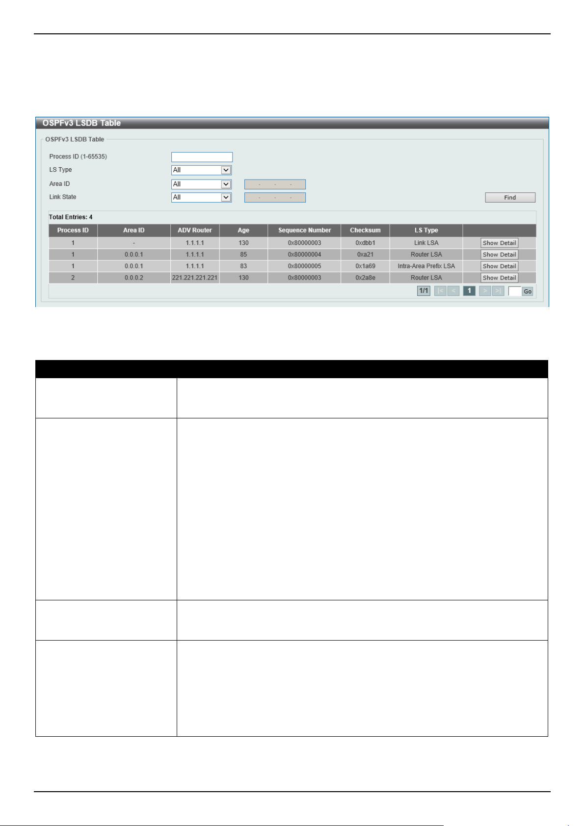
DGS-1520 Series Gigabit Ethernet Smart Managed Switch Web UI Reference Guide
274
OSPFv3 LSDB Table
This window is used to find and display the OSPFv3 LSDB information.
To view the following window, click L3 Features > OSPF > OSPFv3 > OSPFv3 LSDB Table, as shown below:
Figure 6-65 OSPFv3 LSDB Table Window
The fields that can be configured are described below:
Parameter Description
Process ID
Enter the ID for an IPv6 OSPF routing process here. It is locally assigned and
should be unique for each IPv6 OSPF routing process on the router. The range is
from 1 to 65535.
LSDB Type
Select the LSDB display type here. Options to choose from are:
• All - Specifies to display all types of LSDB information.
• Router LSA - Specifies to display information only about the router LSAs.
• Network LSA - Specifies to display information only about the network
LSAs.
• Prefix - Specifies to display information on the intra-area-prefix LSAs.
• Link LSA - Specifies to display information about the link LSAs.
• Inter-Area Prefix LSA - Specifies to display information only about LSAs
based on inter-area prefix LSAs.
• Inter-Area Router LSA - Specifies to display information only about LSAs
based on inter-area router LSAs.
• AS External LSA - Specifies to display information only about the external
LSAs.
Area ID Select the area ID option here. Options to choose from are All and Area ID. To
display all the LSAs of the specified area, select the Area ID option and enter the
OSPF area ID in the space provided. It can be specified as an IPv4 address.
Link State
Select the link state option here. Options to choose from are:
• All - Specifies to display all the LSAs.
• Self-Originate - Specifies to display only self-originated LSAs (from the
local router).
• Adv Router - Specifies to display all the LSAs of the advertising router.
Enter the router ID in the space provided. The router ID can be specified as
an IPv4 address.
Click the Find button to locate a specific entry based on the information entered.
Click the Show Detail button to view detailed information for the specified entry.
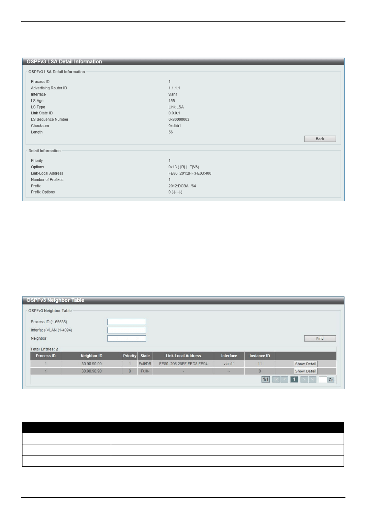
DGS-1520 Series Gigabit Ethernet Smart Managed Switch Web UI Reference Guide
275
Enter a page number and click the Go button to navigate to a specific page when multiple pages exist.
After clicking the Show Detail button, the following page will appear.
Figure 6-66 OSPFv3 LSDB Table (Show Detail) Window
Click the Back button to return to the previous window.
OSPFv3 Neighbor Table
This window is used to find and display the OSPFv3 neighbor information.
To view the following window, click L3 Features > OSPF > OSPFv3 > OSPFv3 Neighbor Table, as shown below:
Figure 6-67 OSPFv3 Neighbor Table Window
The fields that can be configured are described below:
Parameter Description
Process ID
Enter the OSPFv3 process ID to find here. The range is from 1 to 65535.
Interface VLAN
Enter the VLAN interface ID here. The range is from 1 to 4094.
Neighbor
Enter the OSPF neighbor ID here. It can be specified as an IPv4 address.
Click the Find button to locate a specific entry based on the information entered.
Click the Show Detail button to view detailed information for the specified entry.
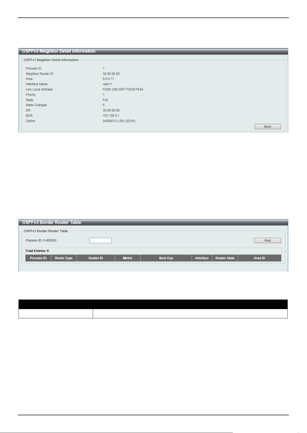
DGS-1520 Series Gigabit Ethernet Smart Managed Switch Web UI Reference Guide
276
Enter a page number and click the Go button to navigate to a specific page when multiple pages exist.
After clicking the Show Detail button, the following page will appear.
Figure 6-68 OSPFv3 Neighbor Table (Show Detail) Window
Click the Back button to return to the previous window.
OSPFv3 Border Router Table
This window is used to find and display the OSPFv3 border router information.
To view the following window, click L3 Features > OSPF > OSPFv3 > OSPFv3 Border Router Table, as shown
below:
Figure 6-69 OSPFv3 Border Router Table Window
The fields that can be configured are described below:
Parameter Description
Process ID
Enter the OSPFv3 process ID to search for here. The range is from 1 to 65535.
Click the Find button to locate a specific entry based on the information entered.
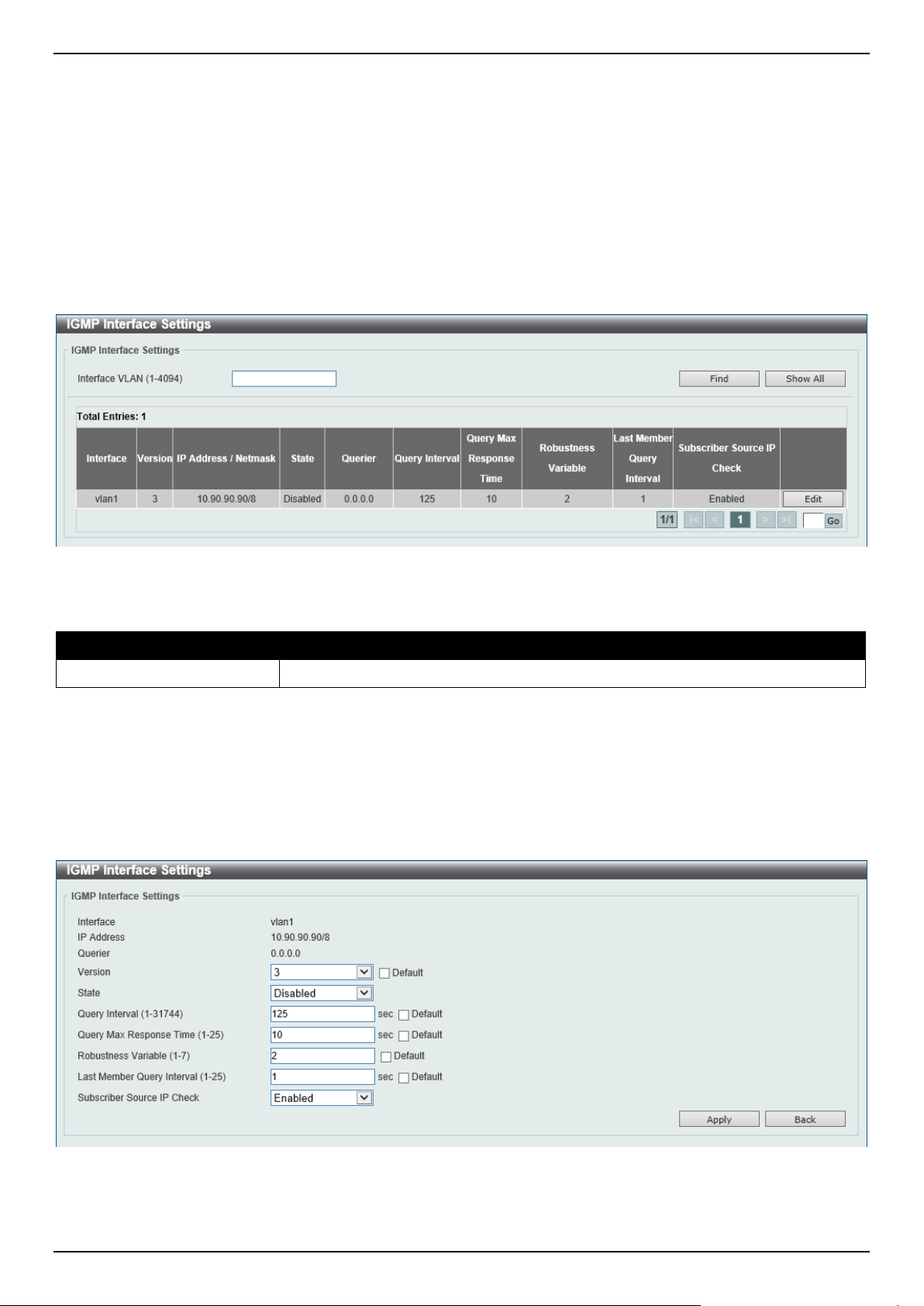
DGS-1520 Series Gigabit Ethernet Smart Managed Switch Web UI Reference Guide
277
IP Multicast Routing Protocol
IGMP
IGMP Interface Settings
The window is used to find and display the Internet Group Management Protocol (IGMP) interface settings.
To view the following window, click L3 Features > IP Multicast Routing Protocol > IGMP > IGMP Interface
Settings, as shown below:
Figure 6-70 IGMP Interface Settings Window
The fields that can be configured are described below:
Parameter Description
Interface VLAN
Enter the VLAN interface ID here. The range is from 1 to 4094.
Click the Find button to locate a specific entry based on the information entered.
Click the Show All button to display all IGMP interface entries.
Click the Edit button to modify the specified entry.
Enter a page number and click the Go button to navigate to a specific page when multiple pages exist.
After clicking the Edit button, the following page will appear.
Figure 6-71 IGMP Interface Settings (Edit) Window

DGS-1520 Series Gigabit Ethernet Smart Managed Switch Web UI Reference Guide
278
The fields that can be configured are described below:
Parameter Description
Version
Select the IGMP version number here. The range is from 1 to 3. By default, this
value is 3.
Select the Default option to use the default version.
State
Select to enable or disable the IGMP state on this interface here.
Query Interval
Enter the query interval value here. The range is from 1 to 31744 seconds. The
IGMP querier sends IGMP query messages at the interval specified here to
discover the receivers attached to the interface interested in joining the multicast
group. Hosts respond to the query with IGMP report messages to indicate the
multicast group they are interested in joining.
Select the Default option to use the default value.
Query Max Reponses Time
Enter the maximum query response time value here. The range is from 1 to 25
seconds. This configures the period of time, which the group member can respond
to an IGMP query message before the router removes the membership. The group
membership lifetime is equal to the query interval times the robustness plus the
maximum response time.
Select the Default option to use the default value.
Robustness Variable
Enter the robustness variable value here. The range is from 1 to 7. The robustness
variable provides fine-tuning to allow for expected packet loss on an interface.
Select the Default option to use the default value.
Last Member Query Interval
Enter the Last Member Query Interval value here. The range is from 1 to 25
seconds. When the router receives a leave message from a receiver to leave a
group or a channel, the router will send the Group Specific Query or Group-Source
Specific Query message to the receiver interface. The IGMP Last Member Query
Interval will be advertised in the query message and conveyed to the receiver. This
configures the period that the router will send the next group-specific query or
group-source specific query message if there is no report from receiver for the
specific group or specific channel. The router will retry for the last member query
count. If no report messages are received after the retry count, the interface will
remove the membership from the specific group or specific channel.
Select the Default option to use the default value.
Subscriber Source IP
Check
Select to enable or disable the subscriber source IP check feature here. By default,
the IGMP report or leave messages received by the interface will be checked to
determine whether its source IP is in the same network as the interface. If they are
not in the same network, the message information won't be learned by the IGMP
protocol.
Click the Back button to return to the previous window.
Click the Apply button to accept the changes made.
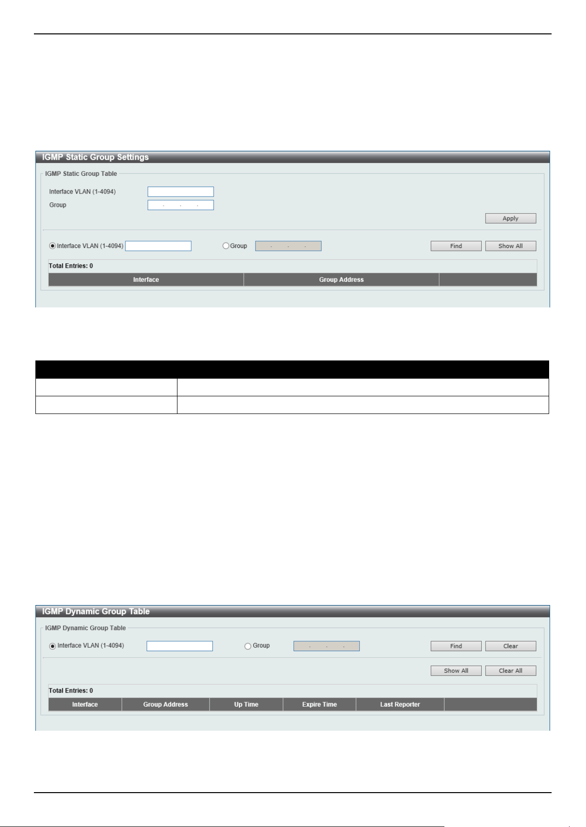
DGS-1520 Series Gigabit Ethernet Smart Managed Switch Web UI Reference Guide
279
IGMP Static Group Settings
This window is used to display and configure the IGMP static group settings. Use this window to create an IGMP static
group in the case that the attached host does not support the IGMP protocol. Once configured, the group member
entry is added to the IGMP cache.
To view the following window, click L3 Features > IP Multicast Routing Protocol > IGMP > IGMP Static Group
Settings, as shown below:
Figure 6-72 IGMP Static Group Settings Window
The fields that can be configured are described below:
Parameter Description
Interface VLAN
Enter the VLAN interface ID here. The range is from 1 to 4094.
Group
Enter the IP multicast group address here.
Click the Apply button to accept the changes made.
Click the Find button to locate a specific entry based on the information entered.
Click the Show All button to display all the entries.
IGMP Dynamic Group Table
This window is used to find, clear and display IGMP dynamic group information. The IGMP buffer includes a list that
contains the dynamic multicast groups that the hosts in the direct subnet join. Use this window to clear the dynamic
group information.
To view the following window, click L3 Features > IP Multicast Routing Protocol > IGMP > IGMP Dynamic Group
Table, as shown below:
Figure 6-73 IGMP Dynamic Group Table Window
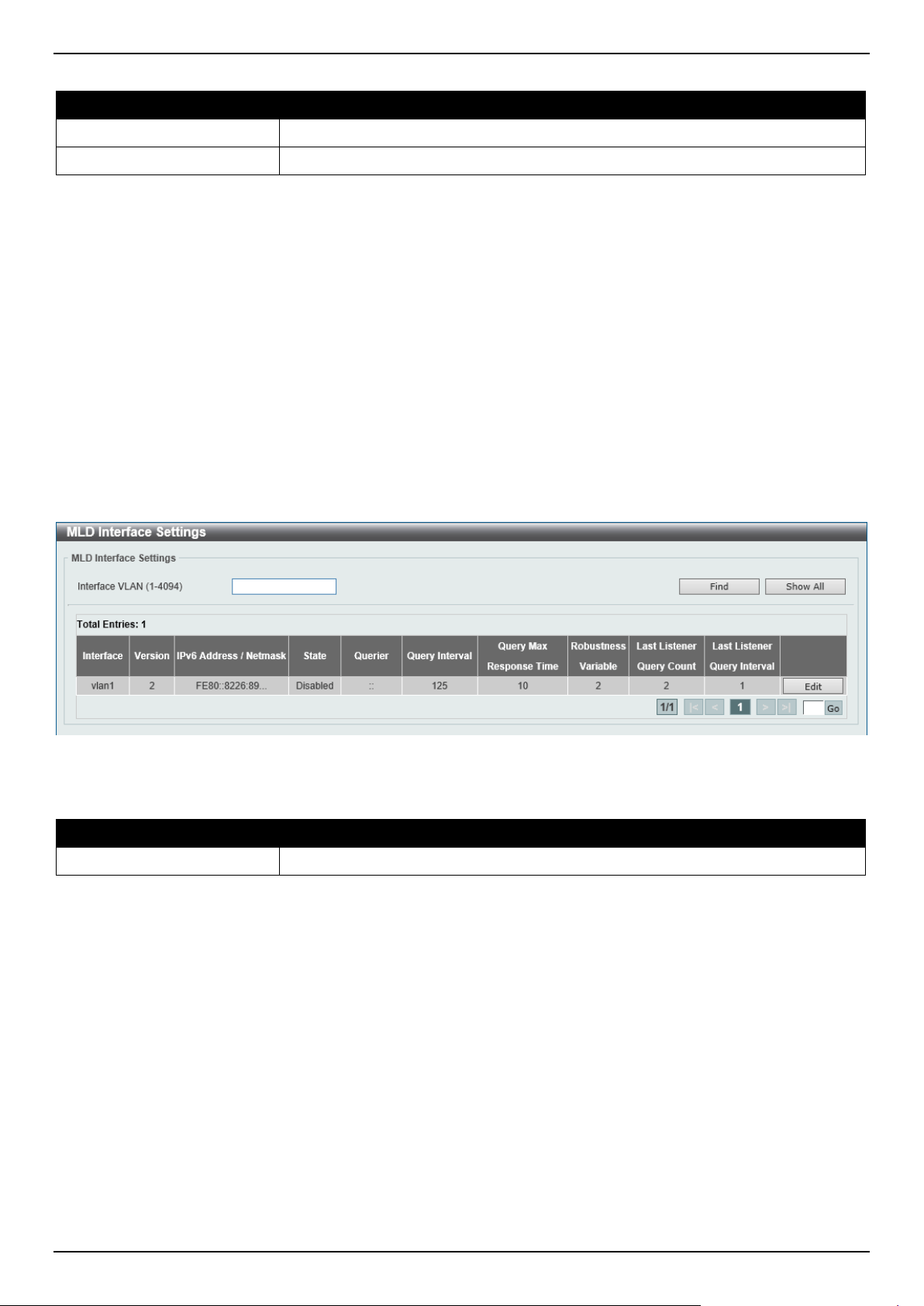
DGS-1520 Series Gigabit Ethernet Smart Managed Switch Web UI Reference Guide
280
The fields that can be configured are described below:
Parameter Description
Interface VLAN
Enter the VLAN interface ID here. The range is from 1 to 4094.
Group
Enter the IP multicast group address here.
Click the Find button to locate a specific entry based on the information entered.
Click the Clear button to clear the entries based on the information specified.
Click the Show All button to display all the entries.
Click the Clear All button to clear all the entries.
MLD
MLD Interface Settings
This window is used to display and configure the Multicast Listener Discovery (MLD) interface settings.
To view the following window, click L3 Features > IP Multicast Routing Protocol > MLD > MLD Interface Settings,
as shown below:
Figure 6-74 MLD Interface Settings Window
The fields that can be configured are described below:
Parameter Description
Interface VLAN
Enter the associated VLAN ID of the interface here. The range is from 1 to 4094.
Click the Find button to locate a specific entry based on the information entered.
Click the Show All button to display all the entries.
Click the Edit button to modify the specified entry.
Enter a page number and click the Go button to navigate to a specific page when multiple pages exist.
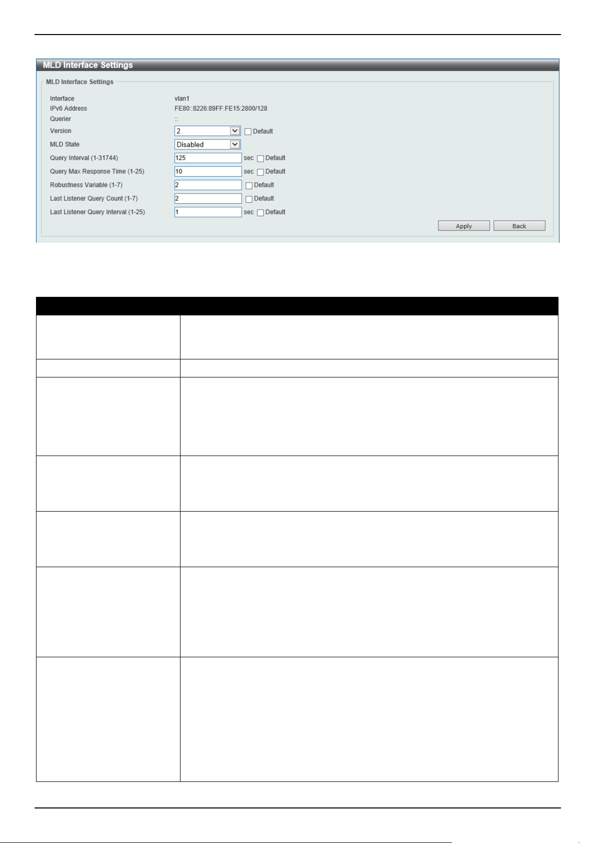
DGS-1520 Series Gigabit Ethernet Smart Managed Switch Web UI Reference Guide
281
After clicking the Edit button, the following page will appear.
Figure 6-75 MLD Interface Settings (Edit) Window
The fields that can be configured are described below:
Parameter Description
Version
Select the MLD version that will be used on the interface here. Options to choose
from are 1 and 2. By default, this value is 2.
Select the Default option to use the default version.
MLD State
Select to enable or disable the MLD feature on this interface here.
Query Interval
Enter the query interval here. This specifies the frequency at which the designated
router sends MLD general-query messages. On receiving the general query, the
MLD listener needs to respond the report packet to claim that it is interested in the
specified multicast group. The range is from 1 to 31744 seconds. By default, this
value is 125 seconds.
Select the Default option to use the default value.
Query Max Response Time
Enter the maximum query response time value here. This specifies the maximum
response time advertised in MLD queries. The range is from 1 to 25 seconds. By
default, this value is 10 seconds.
Select the Default option to use the default value.
Robustness Variable
Enter the robustness variable value here. The robustness variable provides fine-
tuning to allow for expected packet loss on an interface. The range is from 1 to 7.
By default, this value is 2.
Select the Default option to use the default value.
Last Listener Query Count
Enter the last member query count value here. This is used to configure the
number of group-specific or group-source specific queries sent before the router
assumes there are no local members in a group. If the router does not receive
reports from hosts within the timeout period, the router will stop sending the
multicast group traffic to the interface. The range is from 1 to 7. By default, this
value is 2.
Select the Default option to use the default value.
Last Listener Query Interval
Enter the interval for the amount of time between group-specific or group-source-
specific queries here. When an MLD querier receives a packet to leave the group
or channel, it will send a group-specific query or group-source-specific query. The
leave timer starts once the MLD querier receives the packet on an interface. If the
interface does not receive the report packet before the leave timer expires, then
the interface's membership will be removed from the group or channel that it is
leaving. The value of the leave timer is the value of the Last Listener Query
Interval times the Last Listener Query Count. The range is from 1 to 25 seconds.
By default, this value is 1 second.
Select the Default option to use the default value.
Click the Back button to return to the previous window.
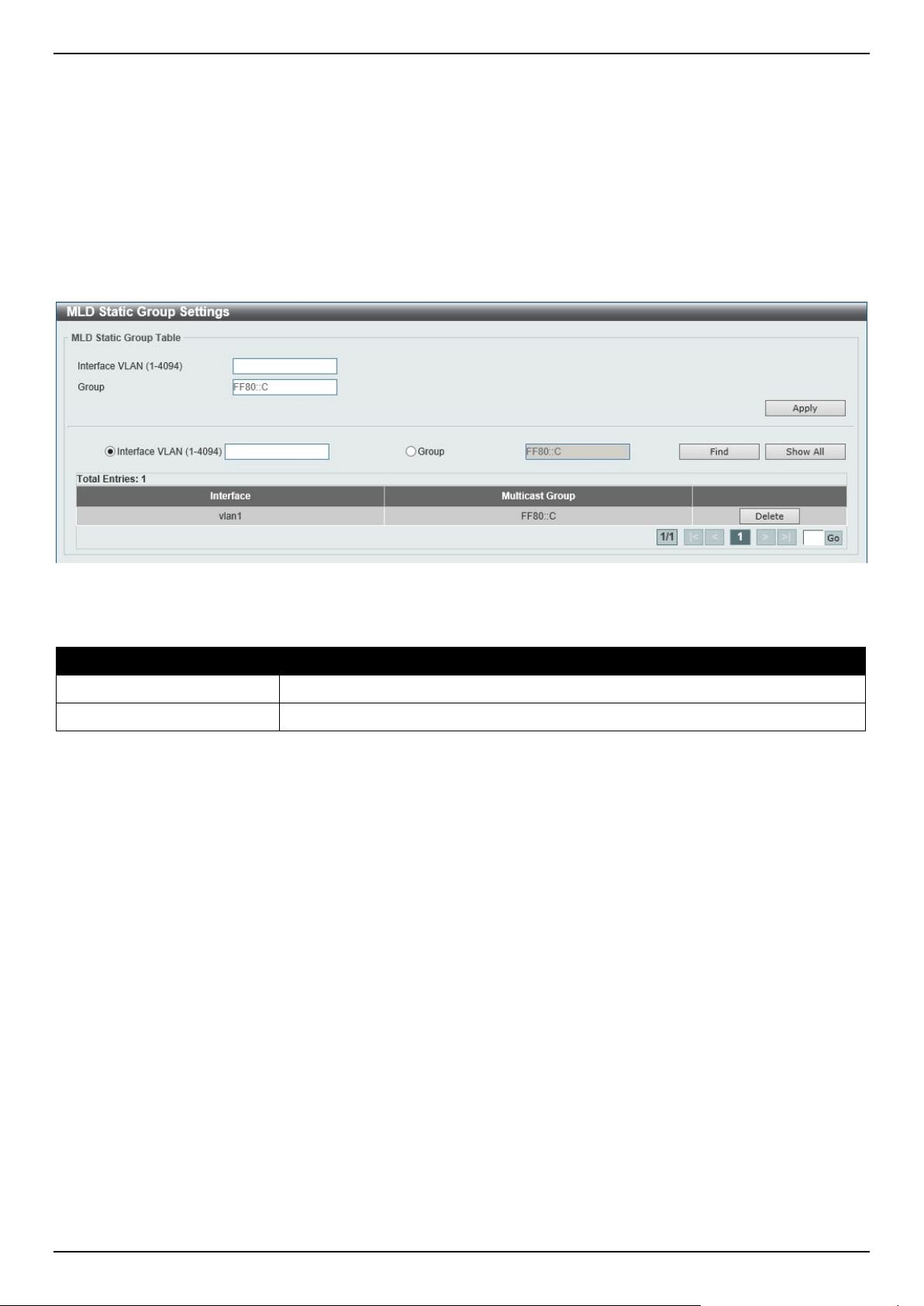
DGS-1520 Series Gigabit Ethernet Smart Managed Switch Web UI Reference Guide
282
Click the Apply button to accept the changes made.
MLD Static Group Settings
This window is used to display and configure the MLD static group settings. Use this window to create an MLD static
group in the case that the attached host does not support the MLD protocol. Once configured, the group member entry
is added to the MLD cache.
To view the following window, click L3 Features > IP Multicast Routing Protocol > MLD > MLD Static Group
Settings, as shown below:
Figure 6-76 MLD Static Group Settings Window
The fields that can be configured are described below:
Parameter Description
Interface VLAN
Enter the VLAN interface ID here. The range is from 1 to 4094.
Group
Enter the IPv6 multicast group address here.
Click the Apply button to accept the changes made.
Click the Find button to locate a specific entry based on the information entered.
Click the Show All button to display all the entries.
Click the Delete button to delete the specified entry.
Enter a page number and click the Go button to navigate to a specific page when multiple pages exist.
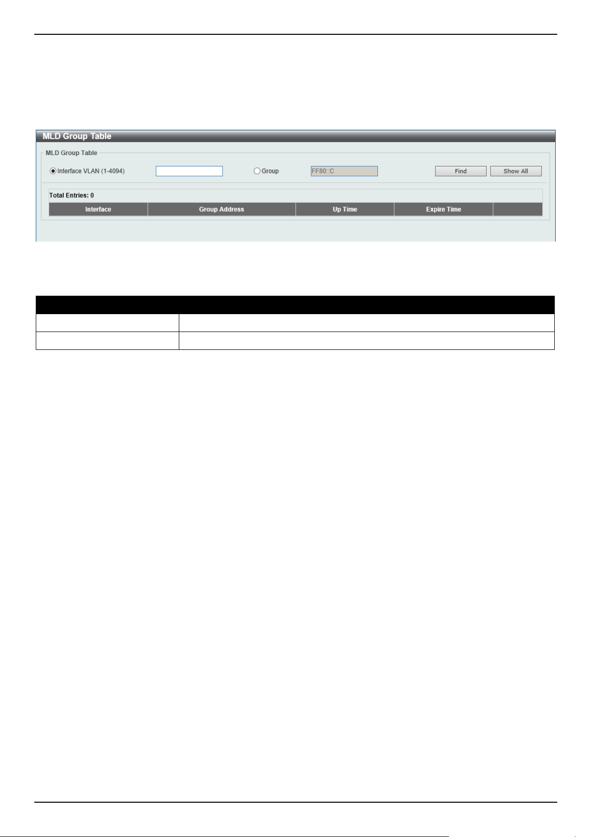
DGS-1520 Series Gigabit Ethernet Smart Managed Switch Web UI Reference Guide
283
MLD Group Table
This window is used to find and display the MLD group information.
To view the following window, click L3 Features > IP Multicast Routing Protocol > MLD > MLD Group Table, as
shown below:
Figure 6-77 MLD Group Table Window
The fields that can be configured are described below:
Parameter Description
Interface VLAN
Enter the VLAN interface ID here. The range is from 1 to 4094.
Group
Enter the group IPv6 address here.
Click the Find button to locate a specific entry based on the information entered.
Click the Show All button to display all the entries.
IGMP Proxy
IGMP Proxy Settings
This window is used to display and configure the IGMP proxy settings. The IGMP proxy only works in a simple tree
topology. Make sure that there are no other multicast routers except for the proxy devices in the simple tree topology.
When receiving IGMP report packets from a downstream interface, IGMP proxy will update its membership database,
which is generated by the merger of all subscriptions on any downstream interface. If the database is changed, the
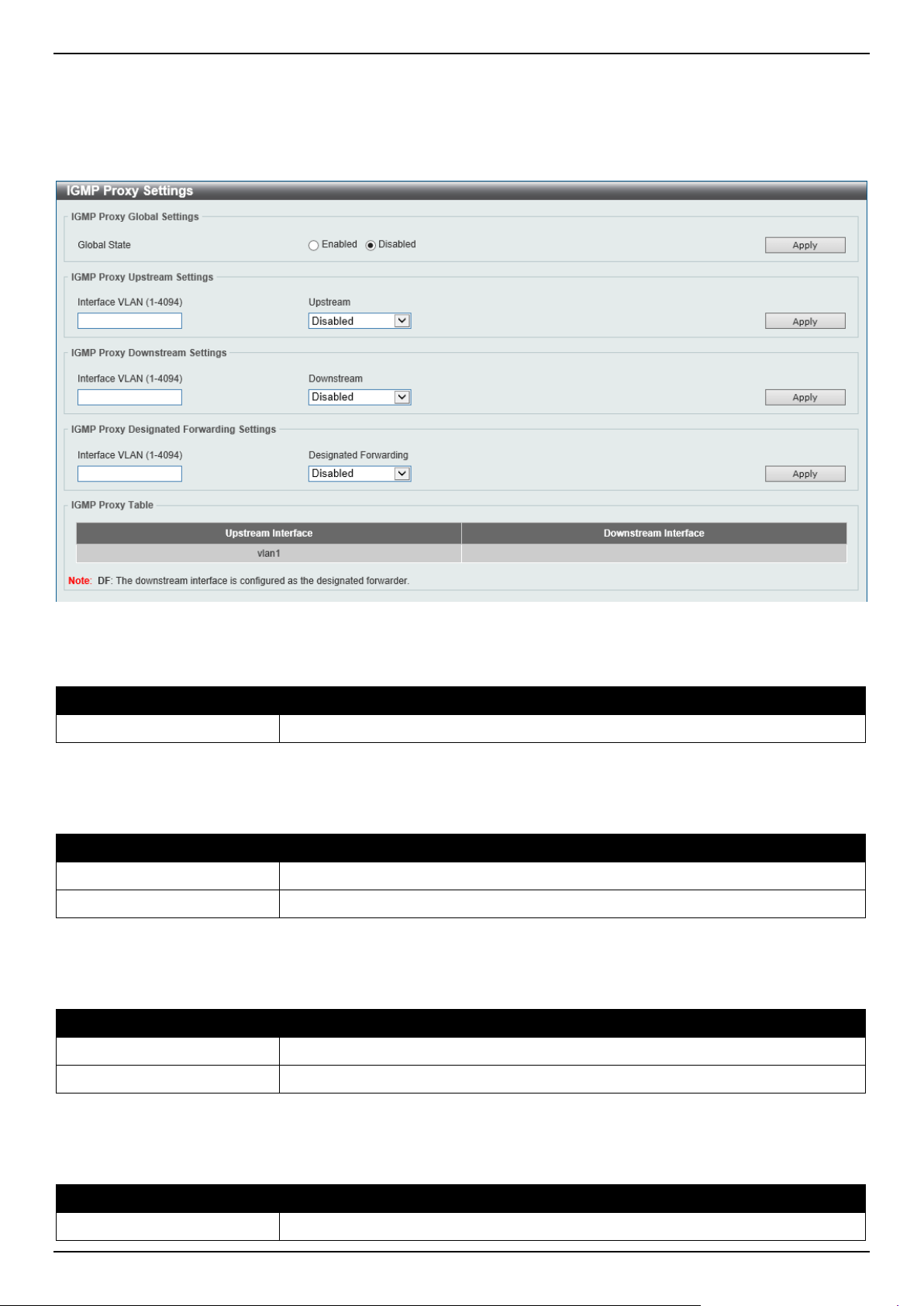
DGS-1520 Series Gigabit Ethernet Smart Managed Switch Web UI Reference Guide
284
proxy device will send unsolicited reports or leaves from the upstream interface. It can also send membership reports
from the upstream interface when queried.
To view the following window, click L3 Features > IP Multicast Routing Protocol > IGMP Proxy > IGMP Proxy
Settings, as shown below:
Figure 6-78 IGMP Proxy Settings Window
The fields that can be configured in IGMP Proxy Global Settings are described below:
Parameter Description
Global State
Select to globally enable or disable the IGMP proxy feature here.
Click the Apply button to accept the changes made.
The fields that can be configured in IGMP Proxy Upstream Settings are described below:
Parameter Description
Interface VLAN
Enter the VLAN interface ID here. The range is from 1 to 4094.
Upstream
Select to enable or disable the interface as the upstream IGMP proxy here.
Click the Apply button to accept the changes made.
The fields that can be configured in IGMP Proxy Downstream Settings are described below:
Parameter Description
Interface VLAN
Enter the VLAN interface ID here. The range is from 1 to 4094.
Downstream
Select to enable or disable the interface as the downstream in IGMP proxy here.
Click the Apply button to accept the changes made.
The fields that can be configured in IGMP Proxy Designated Forwarding Settings are described below:
Parameter Description
Interface VLAN
Enter the VLAN interface ID here. The range is from 1 to 4094.
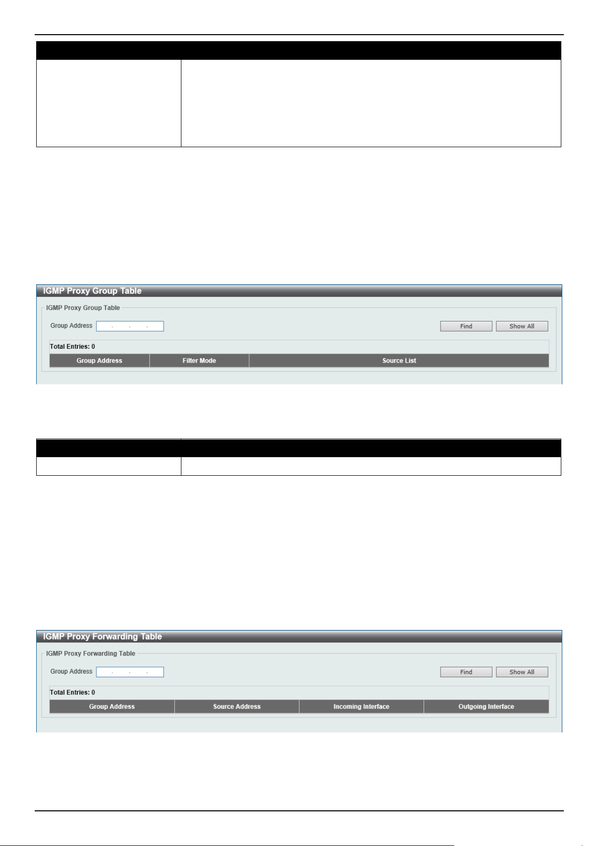
DGS-1520 Series Gigabit Ethernet Smart Managed Switch Web UI Reference Guide
285
Parameter Description
Designated Forwarding
Select to enable or disable designated forwarding on a non-querier IGMP proxy
downstream interface here. To avoid local loops and redundant traffic for links that
are considered downstream links by multiple IGMP-based forwarders, IGMP
proxies use the IGMP querier election to elect a single forwarder on a LAN. Use
this option to make a non-querier device a forwarder. The feature does not take
effect if the interface is not set as the downstream interface or set as the upstream
interface.
Click the Apply button to accept the changes made.
IGMP Proxy Group Table
This window is used to find and display IGMP proxy group information.
To view the following window, click L3 Features > IP Multicast Routing Protocol > IGMP Proxy > IGMP Proxy
Group Table, as shown below:
Figure 6-79 IGMP Proxy Group Table Window
The fields that can be configured are described below:
Parameter Description
Group Address
Enter the IPv4 group multicast address here.
Click the Find button to locate a specific entry based on the information entered.
Click the Show All button to display all the entries.
IGMP Proxy Forwarding Table
This window is used to find and display IGMP proxy forwarding information.
To view the following window, click L3 Features > IP Multicast Routing Protocol > IGMP Proxy > IGMP Proxy
Forwarding Table, as shown below:
Figure 6-80 IGMP Proxy Forwarding Table Window
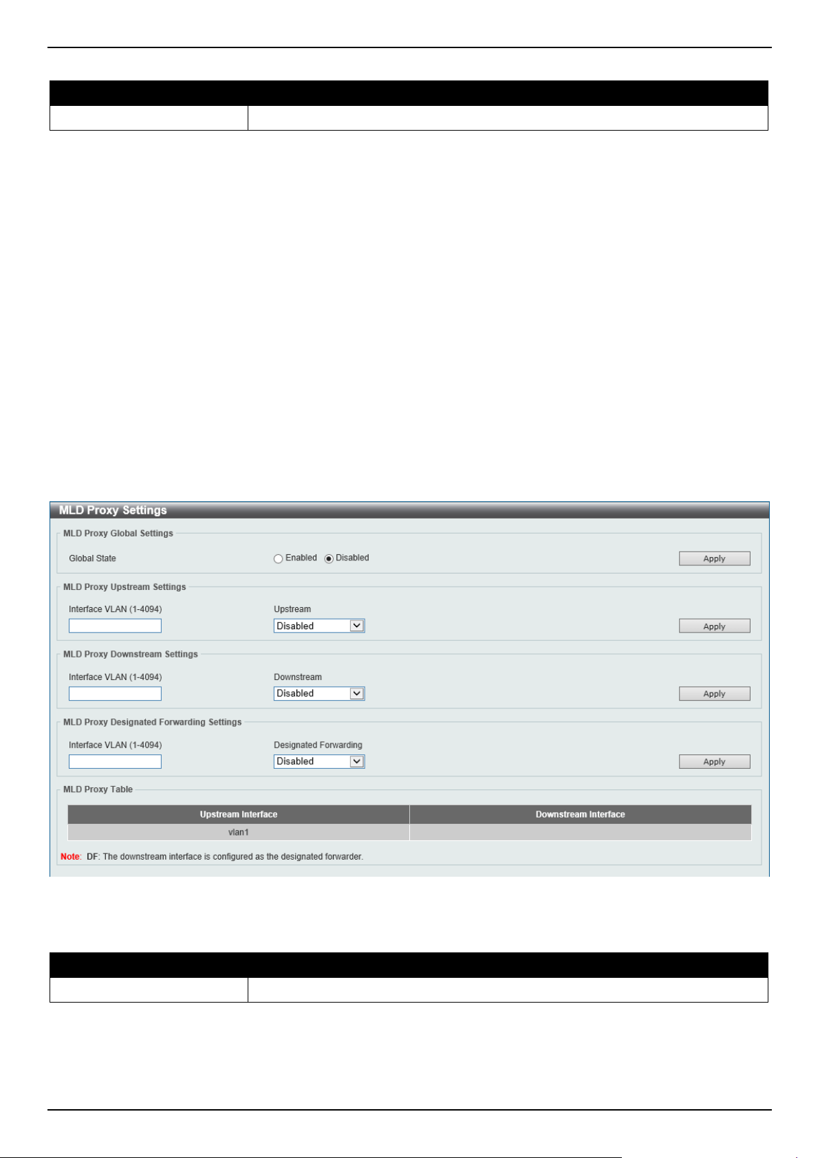
DGS-1520 Series Gigabit Ethernet Smart Managed Switch Web UI Reference Guide
286
The fields that can be configured are described below:
Parameter Description
Group Address
Enter the IPv4 group multicast address here.
Click the Find button to locate a specific entry based on the information entered.
Click the Show All button to display all the entries.
MLD Proxy
MLD Proxy Settings
This window is used to display and configure the MLD proxy settings. The MLD proxy only works in a simple tree
topology. Make sure there are no other multicast routers except for the proxy devices in the tree topology.
When receiving MLD report packet from a downstream interface, MLD proxy will update its membership database,
which is generated by merging all subscriptions on any downstream interface. If the database changes the proxy
device will send unsolicited reports or leaves from the upstream interface. It can also send membership reports from
the upstream interface when queried.
To view the following window, click L3 Features > IP Multicast Routing Protocol > MLD Proxy > MLD Proxy
Settings, as shown below:
Figure 6-81 MLD Proxy Settings Window
The fields that can be configured in MLD Proxy Global Settings are described below:
Parameter Description
Global State
Select to globally enable or disable the MLD proxy feature here.
Click the Apply button to accept the changes made.

DGS-1520 Series Gigabit Ethernet Smart Managed Switch Web UI Reference Guide
287
The fields that can be configured in MLD Proxy Upstream Settings are described below:
Parameter Description
Interface VLAN
Enter the VLAN interface ID here. The range is from 1 to 4094.
Upstream
Select to enable or disable the interface as the upstream MLD proxy here. This
feature only takes effect if the interface has an IPv6 address configured. Only one
upstream interface can exist on an MLD proxy device.
Click the Apply button to accept the changes made.
The fields that can be configured in MLD Proxy Downstream Settings are described below:
Parameter Description
Interface VLAN
Enter the VLAN interface ID here. The range is from 1 to 4094.
Downstream
Select to enable or disable the interface as the downstream MLD proxy here. This
feature only takes effect when the interface has an IPv6 address configured.
Multiple downstream interfaces can be configured on an MLD proxy device.
Click the Apply button to accept the changes made.
The fields that can be configured in MLD Proxy Designated Forwarding Settings are described below:
Parameter Description
Interface VLAN
Enter the VLAN interface ID here. The range is from 1 to 4094.
Designated Forwarding
Select to enable or disable designated forwarding on a non-querier MLD proxy
downstream interface here. To avoid local loops and redundant traffic for links that
are considered downstream links by multiple MLD-based forwarders, MLD proxies
use the MLD querier election to elect a single forwarder on a LAN. Administrators
can use this command to make a non-querier device a forwarder. This feature
does not take effect if the interface is not set as the downstream interface or set as
upstream interface.
Click the Apply button to accept the changes made.
MLD Proxy Group Table
This window is used to find and display MLD proxy group information.
To view the following window, click L3 Features > IP Multicast Routing Protocol > MLD Proxy > MLD Proxy
Group Table, as shown below:
Figure 6-82 MLD Proxy Group Table Window
The fields that can be configured are described below:
Parameter Description
Group Address
Enter the IPv6 group multicast address here.
Click the Find button to locate a specific entry based on the information entered.
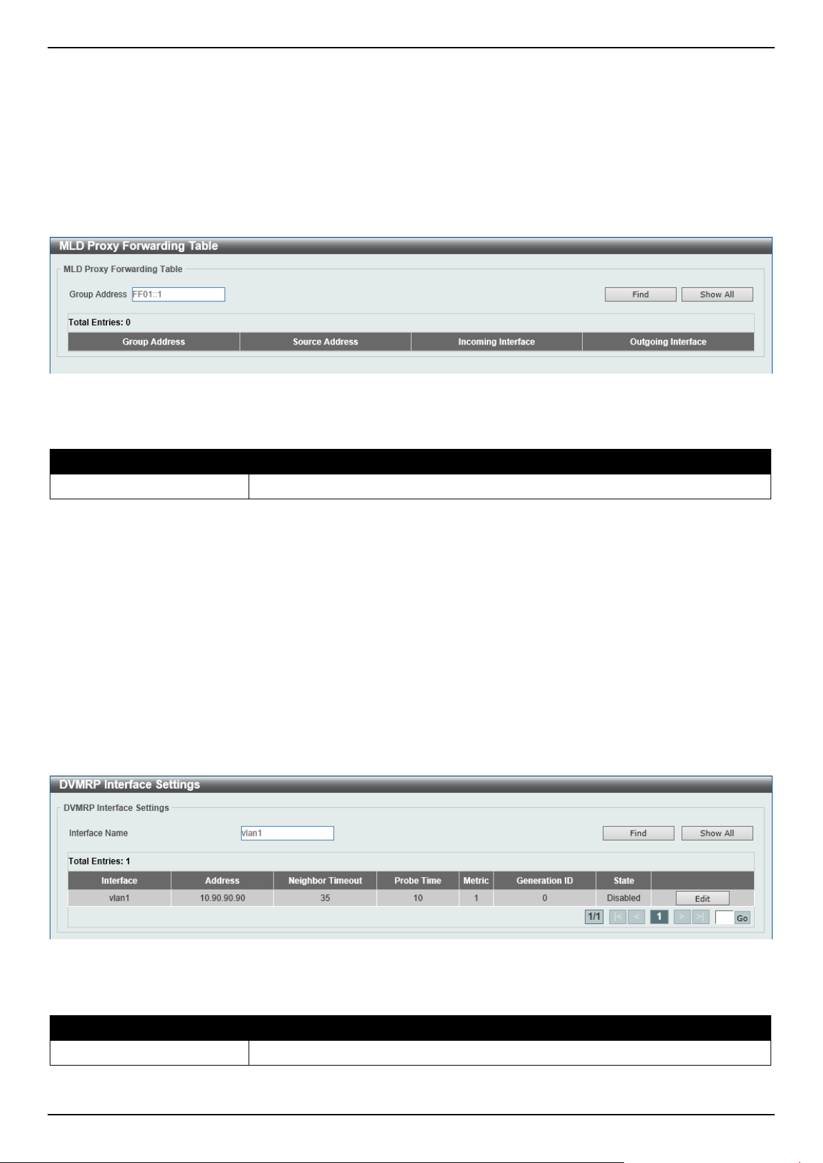
DGS-1520 Series Gigabit Ethernet Smart Managed Switch Web UI Reference Guide
288
Click the Show All button to display all the entries.
MLD Proxy Forwarding Table
This window is used to find and display MLD proxy forwarding information.
To view the following window, click L3 Features > IP Multicast Routing Protocol > MLD Proxy > MLD Proxy
Forwarding Table, as shown below:
Figure 6-83 MLD Proxy Forwarding Table Window
The fields that can be configured are described below:
Parameter Description
Group Address
Enter the IPv6 group multicast address here.
Click the Find button to locate a specific entry based on the information entered.
Click the Show All button to display all the entries.
DVMRP
DVMRP Interface Settings
This window is used to display and configure the Distance Vector Multicast Routing Protocol (DVMRP) interface
settings.
To view the following window, click L3 Features > IP Multicast Routing Protocol > DVMRP > DVMRP Interface
Settings, as shown below:
Figure 6-84 DVMRP Interface Settings Window
The fields that can be configured are described below:
Parameter Description
Interface Name
Enter the VLAN interface name used here.
Click the Find button to locate a specific entry based on the information entered.
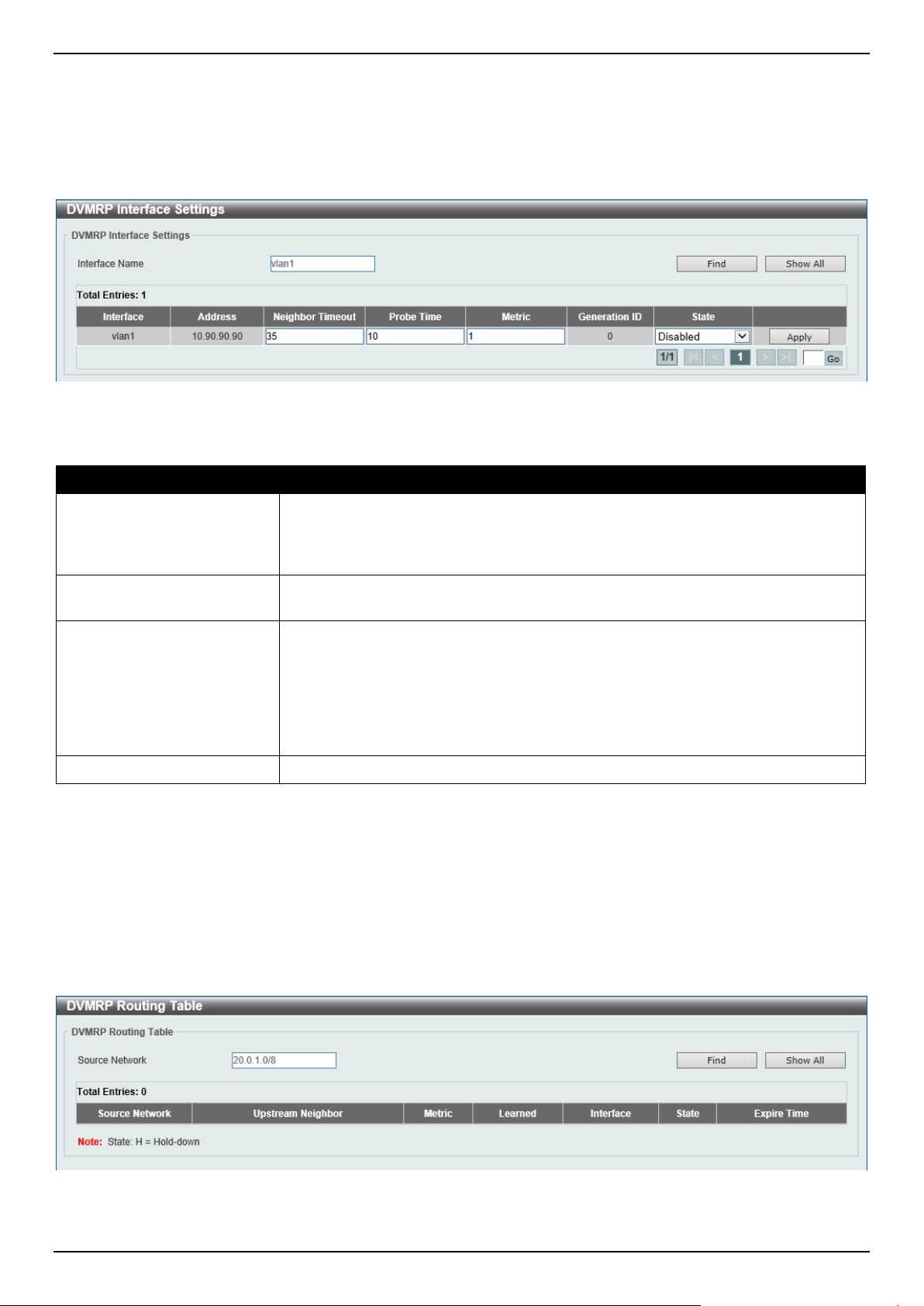
DGS-1520 Series Gigabit Ethernet Smart Managed Switch Web UI Reference Guide
289
Click the Show All button to display all the entries.
Click the Edit button to modify the specified entry.
Enter a page number and click the Go button to navigate to a specific page when multiple pages exist.
After clicking the Edit button, the following page will appear.
Figure 6-85 DVMRP Interface Settings (Edit) Window
The fields that can be configured in the table are described below:
Parameter Description
Neighbor Timeout
Enter the neighbor lifetime value here. If the router has not received a probe
message from a neighbor after the neighbor timeout interval, the neighbor is
considered to be down. The range is from 1 to 65535 seconds. By default, this
value is 35 seconds.
Probe
Enter the DVMRP probe interval value here. The range is from 1 to 65535
seconds. By default, this value is 10 seconds.
Metric
Enter the metric value here. The range is from 1 to 32. A value of 32 means it is
unreachable. For each source network reported, a route metric is associated with
the route being reported. The metric is the sum of the interface metrics between
the router originating the report and the source network. For DVMRP, the metric
with 32 means it is unreachable. This limits the breadth across the whole DVMRP
network and is necessary to place an upper limit on the convergence time of the
protocol.
State
Select to enable or disable the DVMRP feature on the selected interface.
Click the Apply button to accept the changes made.
DVMRP Routing Table
This window is used to find and display DVMRP routing information.
To view the following window, click L3 Features > IP Multicast Routing Protocol > DVMRP > DVMRP Routing
Table, as shown below:
Figure 6-86 DVMRP Routing Table Window

DGS-1520 Series Gigabit Ethernet Smart Managed Switch Web UI Reference Guide
290
The fields that can be configured are described below:
Parameter Description
Source Network
Enter the source IPv4 network address and mask length here.
Click the Find button to locate a specific entry based on the information entered.
Click the Show All button to display all the entries.
DVMRP Neighbor Table
This window is used to find and display DVMRP neighbor information.
To view the following window, click L3 Features > IP Multicast Routing Protocol > DVMRP > DVMRP Neighbor
Table, as shown below:
Figure 6-87 DVMRP Neighbor Table Window
The fields that can be configured are described below:
Parameter Description
Interface name
Enter the VLAN interface name here.
Neighbor IP Address
Select and enter the IPv4 address of the neighbor here.
Click the Find button to locate a specific entry based on the information entered.
Click the Show All button to display all the entries.
PIM
Protocol Independent Multicast (PIM) is a family of multicast routing protocols for Internet Protocol (IP) networks that
provide one-to-many and many-to-many distribution of data over a LAN, WAN or the Internet. PIM is protocol-
independent as it does not include its own topology discovery mechanism, but uses routing information supplied by
other routing protocols, such as RIP or OSPF. The Switch supports four types of PIM, Dense Mode (PIM-DM), Sparse
Mode (PIM-SM), PIM Source Specific multicast (PIM-SSM), and Sparse-Dense Mode (PIM-DM-SM).
PIM-SM
Protocol Independent Multicast - Sparse Mode (PIM-SM) is a multicast routing protocol that can use the underlying
unicast routing information base or a separate multicast-capable routing information base. It builds unidirectional-
shared trees rooted at a Rendezvous Point (RP) per group, and optionally creates shortest-path trees per source.
Unlike most multicast routing protocols, which flood the network with multicast packets, PIM-SM will forward traffic to
routers who are explicitly a part of the multicast group through the use of a Rendezvous Point (RP). This RP will take
all requests from PIM-SM enabled routers, analyze the information, and then return multicast information it receives
from the source to requesting routers within its configured network. Through this method, a distribution tree is created,
with the RP as the root. This distribution tree holds all PIM-SM enabled routers within which information collected from
these routers is stored by the RP.

DGS-1520 Series Gigabit Ethernet Smart Managed Switch Web UI Reference Guide
291
When many routers are a part of a multiple access network, a Designated Router (DR) will be elected. The DR's
primary function is to send Join/Prune messages to the RP. The router with the highest priority on the LAN will be
selected as the DR. If there is a tie for the highest priority, the router with the higher IP address will be chosen.
The third type of router created in the PIM-SM configuration is the Boot Strap Router (BSR). The goal of the Boot
Strap Router is to collect and relay RP information to PIM-SM enabled routers on the LAN. Although the RP can be
statically set, the BSR mechanism can also determine the RP. Multiple Candidate BSRs (C-BSR) can be set on the
network but only one BSR will be elected to process RP information. If it is not specified which C-BSR is to be the
BSR, all C-BSRs will emit Boot Strap Messages (BSM) out on the PIM-SM enabled network to determine which C-
BSR has the higher priority and once determined, will be elected as the BSR. Once determined, the BSR will collect
RP data sent from candidate RPs on the PIM-SM network, compile it and then send it out on the LAN using periodic
Boot Strap Messages (BSM). All PIM-SM Routers will get the RP information from the Boot Strap Mechanism and
then store it in their database.
Discovering and Joining the Multicast Group
Although Hello packets discover PIM-SM routers, these routers can only join or be "pruned" from a multicast group
through the use of Join/Prune Messages exchanged between the DR and RP. Join/Prune Messages are packets
relayed between routers that effectively state which interfaces are, or are not to receive multicast data. The frequency
at which these messages can be sent out on the network can be configured and are only valid to routers if a Hello
packet has first been received. A Hello packet will simply state that the router is present and ready to become a part of
the RP's distribution tree. Once a router has accepted a member of the IGMP group and it is PIM-SM enabled, the
interested router will then send an explicit Join/Prune message to the RP, which will in turn route multicast data from
the source to the interested router, resulting in a unidirectional distribution tree for the group. Multicast packets are
then sent out to all nodes on this tree. Once a prune message has been received for a router that is a member of the
RP's distribution tree, the router will drop the interface from its distribution tree.
Distribution Trees
Two types of distribution trees can exist within the PIM-SM protocol, a Rendezvous-Point Tree (RPT) and a Shortest
Path Tree (SPT). The RP will send out specific multicast data that it receives from the source to all outgoing interfaces
enabled to receive multicast data. Yet, once a router has determined the location of its source, an SPT can be
created, eliminating hops between the source and the destination, such as the RP. This can be configured by the
Switch administrator by setting the multicast data rate threshold. Once the threshold has been passed, the data path
will switch to the SPT. Therefore, a closer link can be created between the source and destination, eliminating hops
previously used and shortening the time a multicast packet is sent from the source to its final destination.
Register and Register-stop Messages
Multicast sources do not always join the intended receiver group. The first hop router (DR) can send multicast data
without being the member of a group or having a designated source, which essentially means it has no information
about how to relay this information to the RP distribution tree. This problem is alleviated through Register and
Register-Stop messages. The first multicast packet received by the DR is encapsulated and sent on to the RP, which
in turn removes the encapsulation and sends the packet down the RP distribution tree. When the route has been
established, a SPT can be created to directly connect routers to the source, or the multicast traffic can flow from the
DR to the RP. When the latter occurs, the same packet may be sent twice, one type encapsulated, one not. The RP
will detect this flaw and then return a Register-stop message to the DR, requesting it to discontinue sending
encapsulated packets.
Assert Messages
At times in the PIM-SM enabled network, parallel paths are created from source to receiver, meaning some receivers
will receive the same multicast packets twice. To improve this situation, Assert messages are sent from the receiving
device to both multicast sources to determine which single router will send the receiver the necessary multicast data.
The source with the shortest metric (hop count) will be elected as the primary multicast source. This metric value is
included within the Assert message.
PIM-SSM
The Source Specific Multicast (SSM) feature is an extension of IP multicast where datagram traffic is forwarded to
receivers from only the multicast sources to which the receivers have explicitly joined. For multicast groups in the SSM
range, only source-specific multicast distribution trees (no shared trees) can be created.

DGS-1520 Series Gigabit Ethernet Smart Managed Switch Web UI Reference Guide
292
The Internet Assigned Numbers Authority (IANA) has reserved the address range from 232.0.0.0 to 232.255.255.255
for SSM applications and protocols. The Switch allows SSM configuration for an arbitrary subset of the IP multicast
address range from 224.0.0.0 to 239.255.255.255.
PIM-DM
The Protocol Independent Multicast - Dense Mode (PIM-DM) protocol should be used in networks with a low delay
(low latency) and high bandwidth, as PIM-DM is optimized to guarantee delivery of multicast packets and not to
reduce overhead.
The PIM-DM multicast routing protocol is assumes that all downstream routers want to receive multicast messages
and relies upon explicit prune messages from downstream routers to remove branches from the multicast delivery tree
that do not contain multicast group members.
PIM-DM has no explicit Join messages. It relies upon periodic flooding of multicast messages to all interfaces and
then either waiting for a timer to expire (the Join/Prune Interval), or for the downstream routers to transmit explicit
Prune messages indicating that there are no multicast members on their respective branches. PIM-DM then removes
these branches (Prunes them) from the multicast delivery tree.
As a member of a pruned branch of a multicast delivery tree may want to join a multicast delivery group (at some point
in the future), the protocol periodically removes the 'prune' information from its database and floods multicast
messages to all interfaces on that branch. The interval for removing 'prune' information is the Join/Prune Interval.
PIM-SM-DM
In the PIM-SM, RP is a key point for the first hop of the sender. If the first hop does not have RP information when the
sender sends information out, it will drop the packet and do nothing. Sparse-Dense mode will be useful in this
condition. In Sparse-Dense mode, the packets can be flooded to all the outgoing interfaces and pruning/joining
(Prune/Graft) can be used to control the outgoing interface list if RP is not found. In other words, the PIM Sparse-
Dense mode is treated in either the sparse mode or dense mode of the operation; it depends on which mode the
multicast group operates. When an interface receives multicast traffic, if there is a known RP for the group, then the
current operation mode on the interface is sparse mode, otherwise the current operation mode on the interface will be
dense mode.
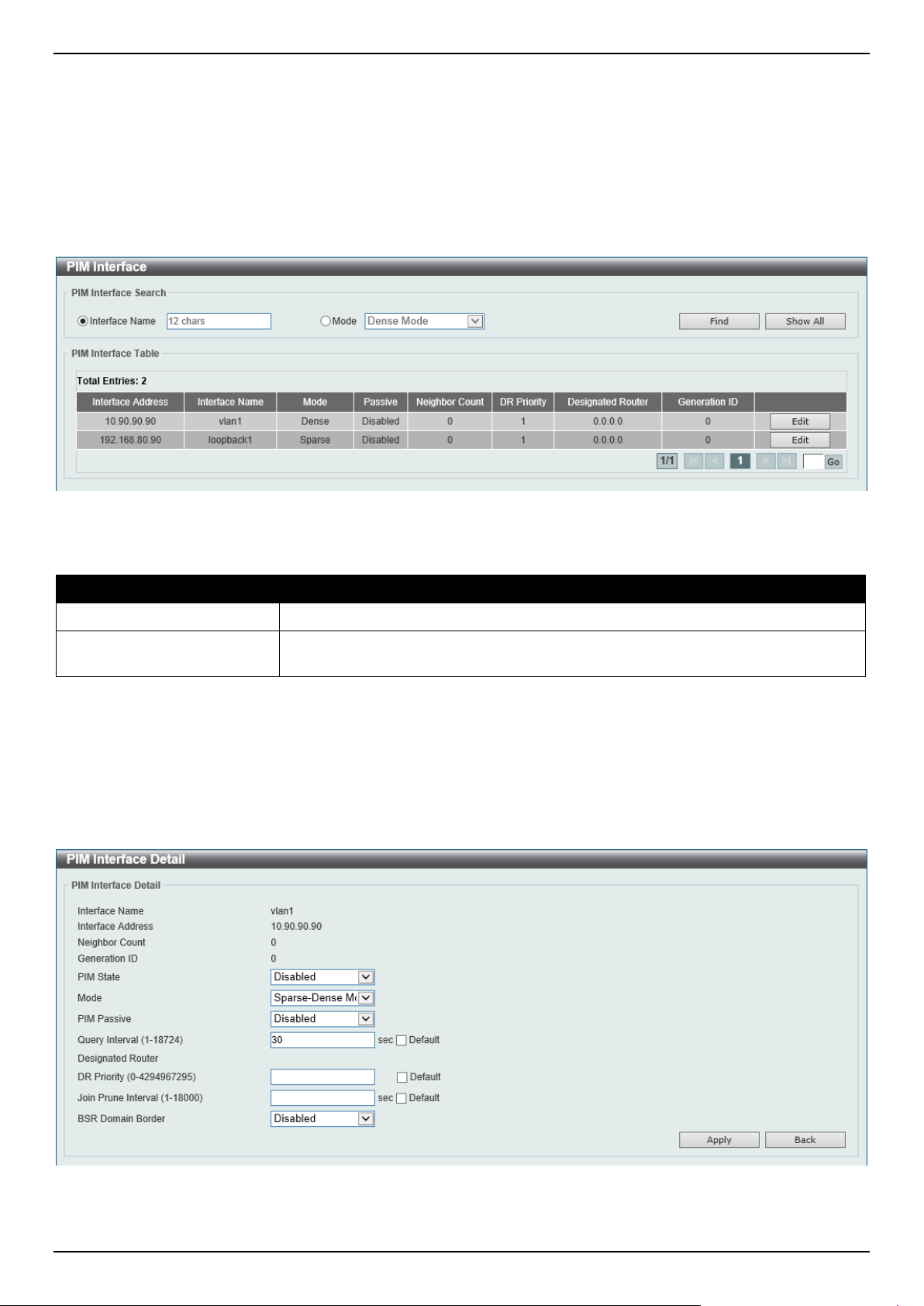
DGS-1520 Series Gigabit Ethernet Smart Managed Switch Web UI Reference Guide
293
PIM for IPv4
PIM Interface
This window is used to display and configure the Protocol Independent Multicast (PIM) interface settings.
To view the following window, click L3 Features > IP Multicast Routing Protocol > PIM > PIM for IPv4 > PIM
Interface, as shown below:
Figure 6-88 PIM Interface Window
The fields that can be configured are described below:
Parameter Description
Interface Name
Select and enter the name of the interface here.
Mode
Select the operation mode of PIM entries used in this filtered search here. Options
to choose from are Dense Mode, Sparse Mode, and Sparse-Dense Mode.
Click the Find button to locate a specific entry based on the information entered.
Click the Show All button to display all the entries.
Click the Edit button to modify the specified entry.
Enter a page number and click the Go button to navigate to a specific page when multiple pages exist.
After clicking the Edit button, the following page will appear.
Figure 6-89 PIM Interface (Edit) Window

DGS-1520 Series Gigabit Ethernet Smart Managed Switch Web UI Reference Guide
294
The fields that can be configured are described below:
Parameter Description
PIM State
Select to enable or disable the PIM state on this interface here.
Mode
Select the PIM mode here. Options to choose from are:
• Dense Mode - PIM-DM assumes that when a source starts sending, all
downstream routers wants to receive the multicast data stream. Initially
multicast data stream are flooded to all downstream routers and the
interfaces that have group members. If there are no downstream routers or
group members, the router will send prune message to indicate that the
multicast data stream is not desired.
• Sparse Mode - When multicast traffic is received on a sparse mode
interface, the first hop router will encapsulate and send the register
message to RP. If the router is not the first hop router, the traffic will be
forwarded based on the Multicast Route entry. A sparse mode interface will
only be populated as Multicast Route member interface if receive join
message from the downstream router or if group member on a sparse mode
interface, PIM join process will be triggered to create the shared tree or the
source tree.
• Sparse-Dense Mode - When interface is configured as PIM Sparse-Dense
mode, a multicast group received by the interface can operate in either
sparse mode or dense mode of operation. When the interface receives
multicast traffic, if there is a known RP for the group, then this group will
operate in sparse mode, otherwise this multicast group will operate in dense
mode.
PIM Passive
Select to enable or disable the PIM passive feature here. When the passive mode
is enabled, the interface will neither send PIM messages out nor accept PIM
messages from this interface. The router will act as if it is the only PIM router on
the network. Use this feature only when there is only one PIM router on the LAN.
Query Interval
Enter the interval at which hello messages are sent here. The range is from 1 to
18724 seconds. A PIMv2 router learns PIM neighbors via the PIM hello message.
This feature configures the frequency of the hello message. Routers configured for
IP multicasting send PIM hello messages to detect PIM routers. For SM, hello
messages also determine the router to act as the designated router for each LAN
segment. The configured query interval is also used as the value for hold time. By
configuring a smaller period for the interval, the unresponsive neighbor can be
discovered faster and thus the failover and recovery will become more efficient. By
default, this value is 30 seconds.
Select the Default option to use the default value.
DR Priority After selecting to use the Sparse Mode or the Sparse-Dense Mode, this
parameter will be available. Enter the Designated Router's (DR) priority value here.
The range is from 0 to 4294967295. A larger value represents the higher priority.
In the Dense Mode (DM), the DR priority option will not be carried in the hello
message. The router with the highest priority value will be the DR. If multiple
routers are with the same priority status, the router with the highest IP address will
be the DR. If there is a router that does not support the DR priority in its hello
message on the LAN, all routers on the LAN will ignore DR priority and only use IP
address to elect DR. By default, this value is 1.
Select the Default option to use the default value.
Join Prune Interval After selecting to use the Sparse Mode or the Sparse-Dense Mode, this
parameter will be available. Enter the Join/Prune message interval value here. The
range is from 1 to 18000 seconds. When configuring the Join/Prune interval,
consider the factors, such as the configured bandwidth and expected average
number of multicast route entries for the attached network or link. For the Sparse
Mode (SM), routers will periodically send join messages based on this interval. The
hold-time in a Join/Prune message is 3.5 times the join-prune-interval. The
receiving router will start a timer based on this hold-time, and prune the interface if
no join message was received on this interface. By default, this value is 60
seconds.
Select the Default option to use the default value.
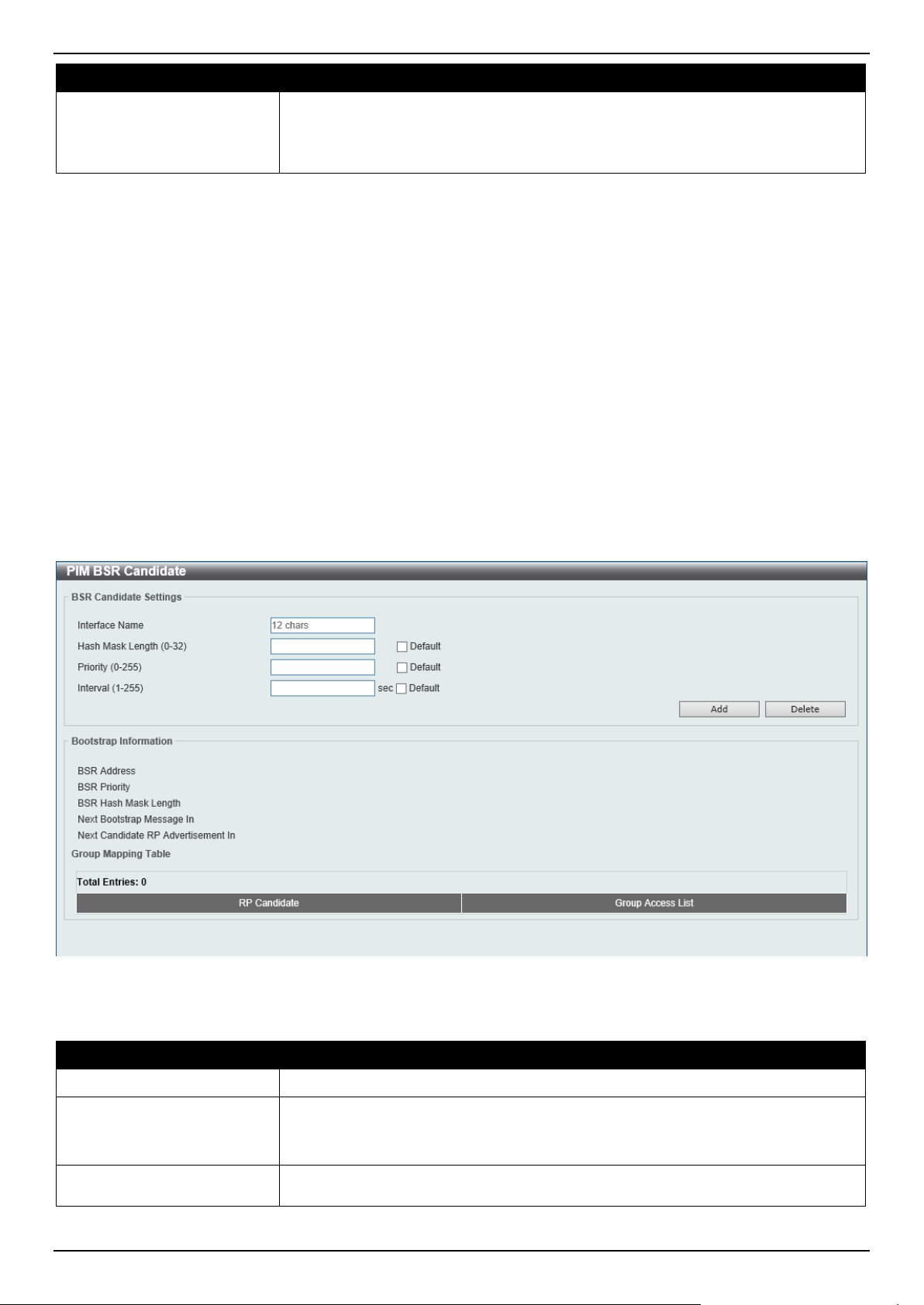
DGS-1520 Series Gigabit Ethernet Smart Managed Switch Web UI Reference Guide
295
Parameter Description
BSR Domain Border
Select to enable or disable the Bootstrap Router (BSR) domain border feature
here. The feature only takes effect when the interface is PIM enabled. Use this
feature on the interface that border with another domain to avoid the exchange of
BSR messages across two domains.
Click the Apply button to accept the changes made.
Click the Back button to return to the previous window.
PIM BSR Candidate
This window is used to display and configure the PIM BSR candidate settings. This feature only takes effect when the
interface has an IP address configured and is in the PIM sparse mode.
This feature causes the router to send bootstrap messages to announce the IP address of the designated interface as
the CBSR address. The hash mask is used by all routers within a domain, to map a group to one of the Rendezvous
Points (RP) from the matching set of group-range-to-RP maps (this set all have the same longest mask length and
same highest priority). The algorithm takes as an input the group address and the addresses of the candidate RPs
from the maps, and gives as an output one RP address to be used.
To view the following window, click L3 Features > IP Multicast Routing Protocol > PIM > PIM for IPv4 > PIM BSR
Candidate, as shown below:
Figure 6-90 PIM BSR Candidate Window
The fields that can be configured are described below:
Parameter Description
Interface Name
Enter the name of the interface here.
Hash Mask Length
Enter the hash mask length for RP selection here. The range is from 0 to 32. By
default, this value is 30.
Select the Default option to use the default value.
Priority
Enter the Candidate Bootstrap Router (CBSR) priority value here. The candidate
with the highest priority is preferred. If the priority values are the same, the router
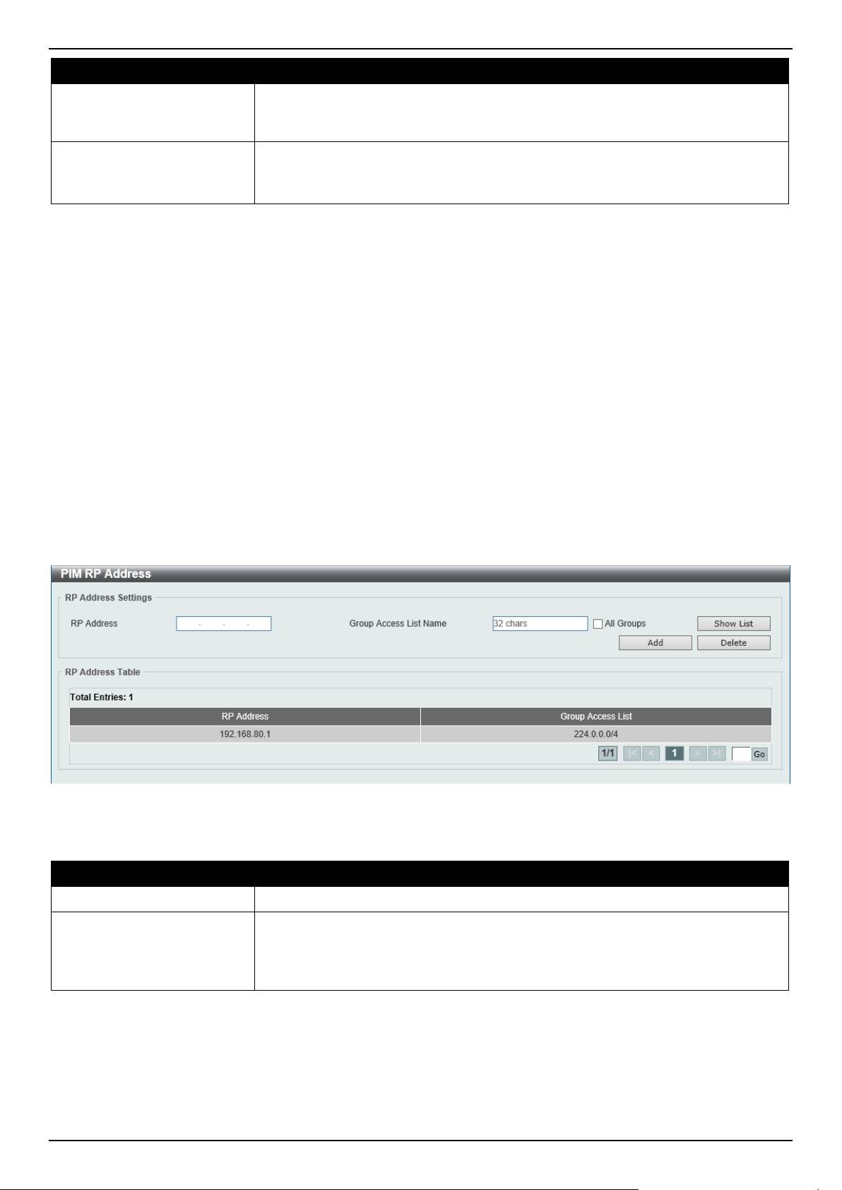
DGS-1520 Series Gigabit Ethernet Smart Managed Switch Web UI Reference Guide
296
Parameter Description
with the highest IP address is preferred. The range is from 0 to 255. By default,
this value is 64.
Select the Default option to use the default value.
Interval
Enter the interval value between originating bootstrap messages here. The range
is from 1 to 255 seconds. By default, this value is 60 seconds.
Select the Default option to use the default value.
Click the Add button to add a new entry based on the information entered.
Click the Delete button to delete an entry based on the information entered.
PIM RP Address
This window is used to display and configure the static multicast groups to RP mapping. In a multicast domain, the
static multicast group to RP mapping can be used together with BSR. All routers in a domain should have a consistent
multicast group to RP mapping. The first hop router that initiates a register message will use the mapping entries to
determine the RP for sending the PIM register message destined for a specific group. The last hop router that initiates
a join message uses the mapping entries to determine the RP for sending the join and prune message for a specific
group. When a router receives a join message, it will check the mapping entries for forwarding of the message. When
a RP receives a register message, if the router is not the right RP for the multicast group, a register-stop message will
be sent.
Multiple RPs can be defined, each with a single access list.
To view the following window, click L3 Features > IP Multicast Routing Protocol > PIM > PIM for IPv4 > PIM RP
Address, as shown below:
Figure 6-91 PIM RP Address Window
The fields that can be configured are described below:
Parameter Description
RP Address
Enter the RP IPv4 address here.
Group Access List Name Enter the standard access list that will be used here. Alternatively, click the Show
List button to find and select any of the exiting ACL configured on this Switch to be
used in this configuration.
Select the All Groups option to map the RP to all multicast groups.
Click the Add button to add a new entry based on the information entered.
Click the Delete button to delete an entry based on the information entered.
Enter a page number and click the Go button to navigate to a specific page when multiple pages exist.
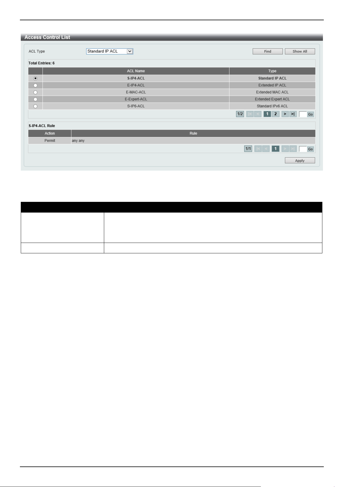
DGS-1520 Series Gigabit Ethernet Smart Managed Switch Web UI Reference Guide
297
After clicking the Show List button, the following page will appear.
Figure 6-92 PIM RP Address (Show List) Window
The fields that can be configured are described below:
Parameter Description
ACL Type
Select the ACL type that will be used to display the type of existing access lists in
the table here. Options to choose from are Standard IP ACL, Extended IP ACL,
Standard IPv6 ACL, Extended IPv6 ACL, Extended MAC ACL, and Extended
Expert ACL.
ACL List
Select the radio button of the access list in the table that will be used here.
Click the Find button to display a list of access lists based on the selection made.
Click the Show All button to display all configured access lists.
Enter a page number and click the Go button to navigate to a specific page when multiple pages exist.
Click the Apply button to use the selected access list.
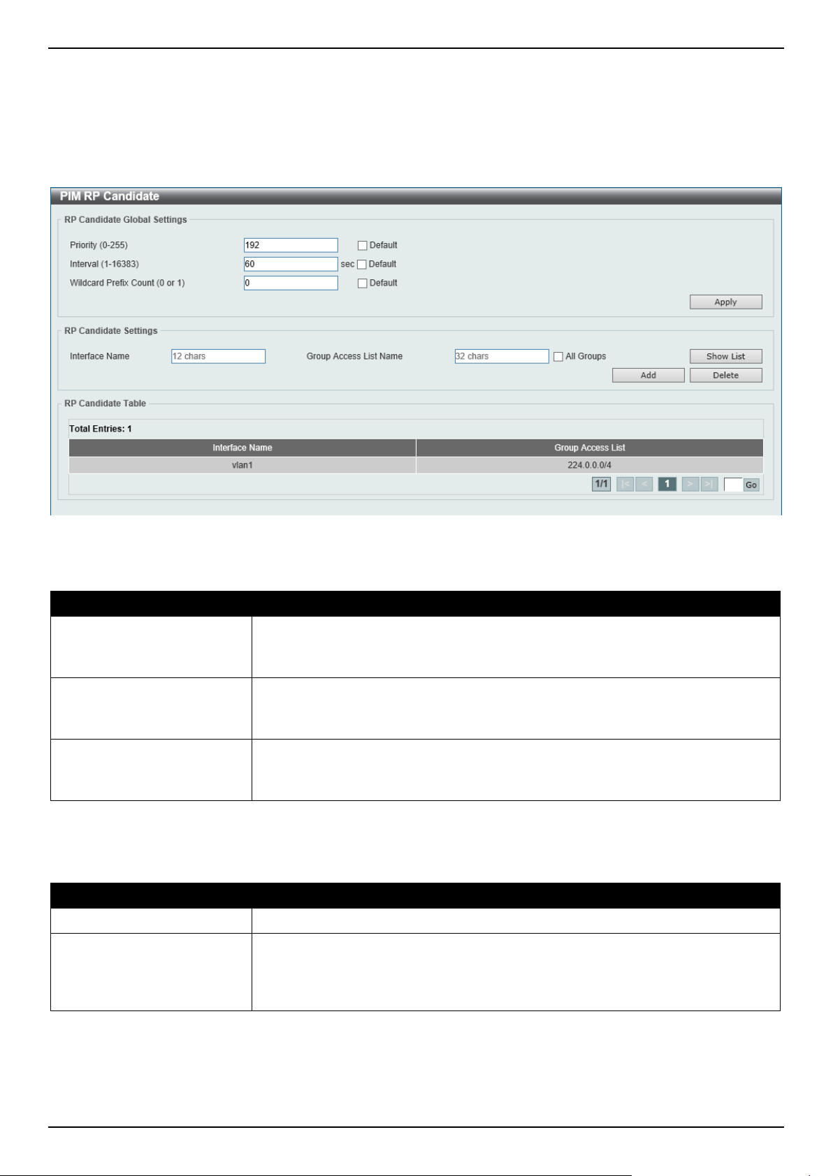
DGS-1520 Series Gigabit Ethernet Smart Managed Switch Web UI Reference Guide
298
PIM RP Candidate
This window is used to display and configure the PIM RP candidate settings.
To view the following window, click L3 Features > IP Multicast Routing Protocol > PIM > PIM for IPv4 > PIM RP
Candidate, as shown below:
Figure 6-93 PIM RP Candidate Window
The fields that can be configured in RP Candidate Global Settings are described below:
Parameter Description
Priority
Enter the candidate RP's priority value here. The range is from 0 to 255. By
default, this value is 192.
Select the Default option to use the default value.
Interval
Enter the candidate RP's advertisement interval value here. The range is from 1 to
16383 seconds. By default, this value is 60 seconds.
Select the Default option to use the default value.
Wildcard Prefix Count
Enter the multicast group address wildcard (224.0.0.0/4) prefix count value in the
C-RP message here. This value can either be 1 or 0. By default, this value is 0.
Select the Default option to use the default value.
Click the Apply button to accept the changes made.
The fields that can be configured in RP Candidate Settings are described below:
Parameter Description
Interface Name
Enter the name of the interface here.
Group Access List Name Enter the standard access list that will be used here. Alternatively, click the Show
List button to find and select any of the exiting access lists configured on this
Switch to be used in this configuration.
Select the All Groups option to map the candidate RP to all multicast groups.
Click the Add button to add a new entry based on the information entered.
Click the Delete button to delete an entry based on the information entered.
Enter a page number and click the Go button to navigate to a specific page when multiple pages exist.
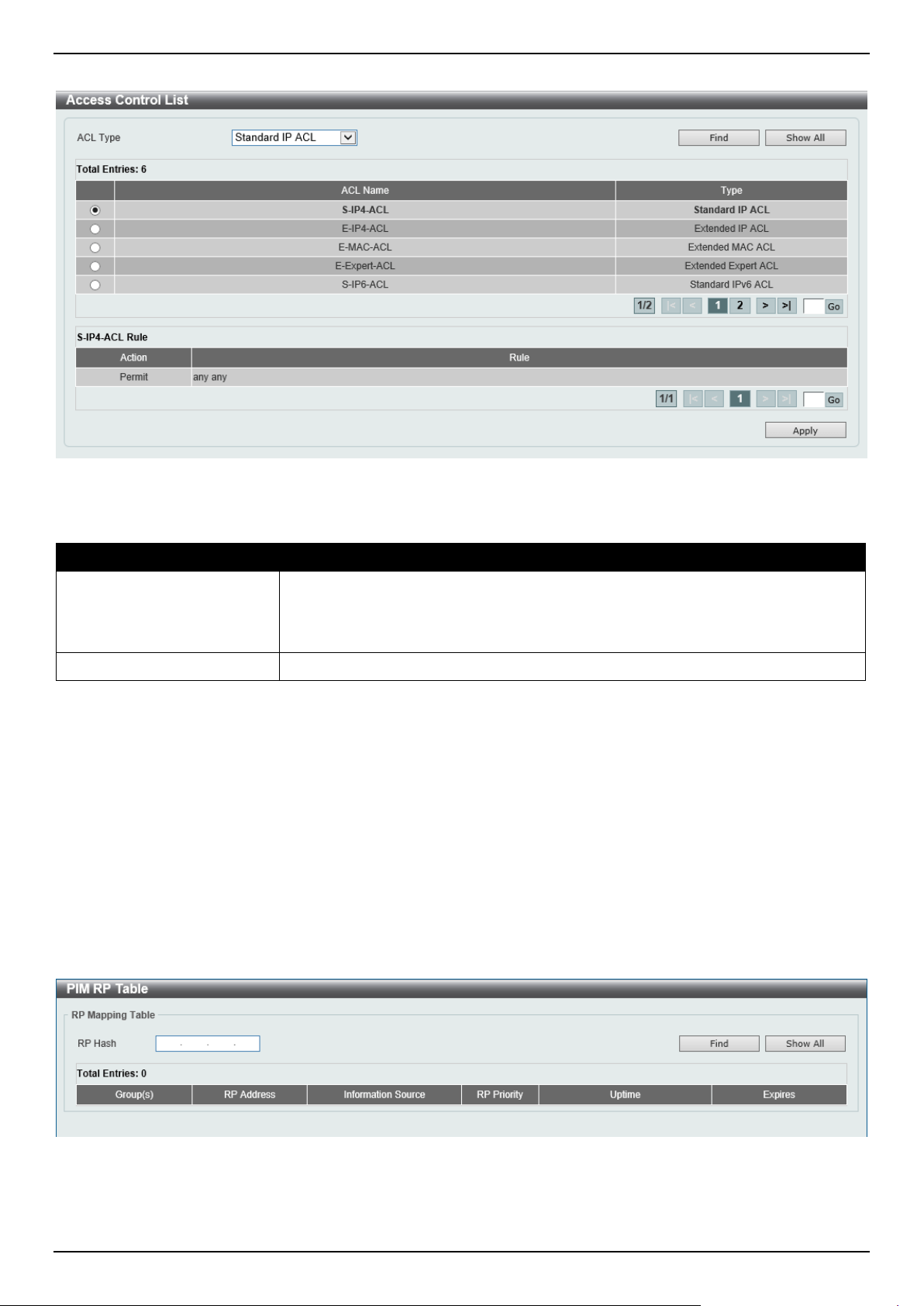
DGS-1520 Series Gigabit Ethernet Smart Managed Switch Web UI Reference Guide
299
After clicking the Show List button, the following page will appear.
Figure 6-94 PIM RP Candidate (Show List) Window
The fields that can be configured are described below:
Parameter Description
ACL Type
Select the ACL type that will be used to display the type of existing access lists in
the table here. Options to choose from are Standard IP ACL, Extended IP ACL,
Standard IPv6 ACL, Extended IPv6 ACL, Extended MAC ACL, and Extended
Expert ACL.
ACL List
Select the radio button of the access list in the table that will be used here.
Click the Find button to display a list of access lists based on the selection made.
Click the Show All button to display all configured access lists.
Enter a page number and click the Go button to navigate to a specific page when multiple pages exist.
Click the Apply button to use the selected access list.
PIM RP Table
This window is used to find and display PIM RP information.
To view the following window, click L3 Features > IP Multicast Routing Protocol > PIM > PIM for IPv4 > PIM RP
Table, as shown below:
Figure 6-95 PIM RP Table Window
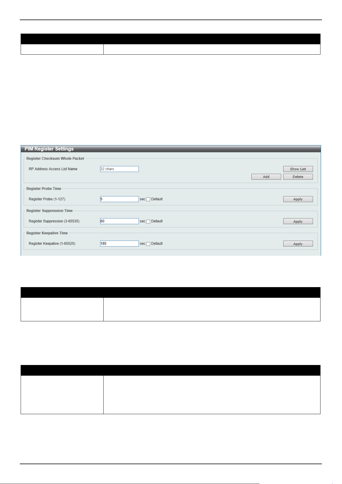
DGS-1520 Series Gigabit Ethernet Smart Managed Switch Web UI Reference Guide
300
The fields that can be configured are described below:
Parameter Description
RP Hash
Enter the IPv4 multicast group address here.
Click the Find button to display a list of access lists based on the selection made.
Click the Show All button to display all configured access lists.
PIM Register Settings
This window is used to display and configure the PIM register settings.
To view the following window, click L3 Features > IP Multicast Routing Protocol > PIM > PIM for IPv4 > PIM
Register Settings, as shown below:
Figure 6-96 PIM Register Settings Window
The fields that can be configured in Register Checksum Wholepkt are described below:
Parameter Description
RP Address Access List
Name
Enter the standard access list that will be used here. Alternatively, click the Show
List button to find and select any of the exiting access lists configured on this
Switch to be used in this configuration.
Click the Add button to add a new entry based on the information entered.
Click the Delete button to delete an entry based on the information entered.
The fields that can be configured in Register Probe Time are described below:
Parameter Description
Register Probe
Enter the register probe time value here. The range is from 1 to 127 seconds. The
register probe time is the time before the Register Stop Timer (RST) expires when
a DR may send a Null-Register to the RP to cause it to resend a Register-Stop
message. By default, this value is 5 seconds.
Select the Default option to use the default value.
Click the Apply button to accept the changes made.
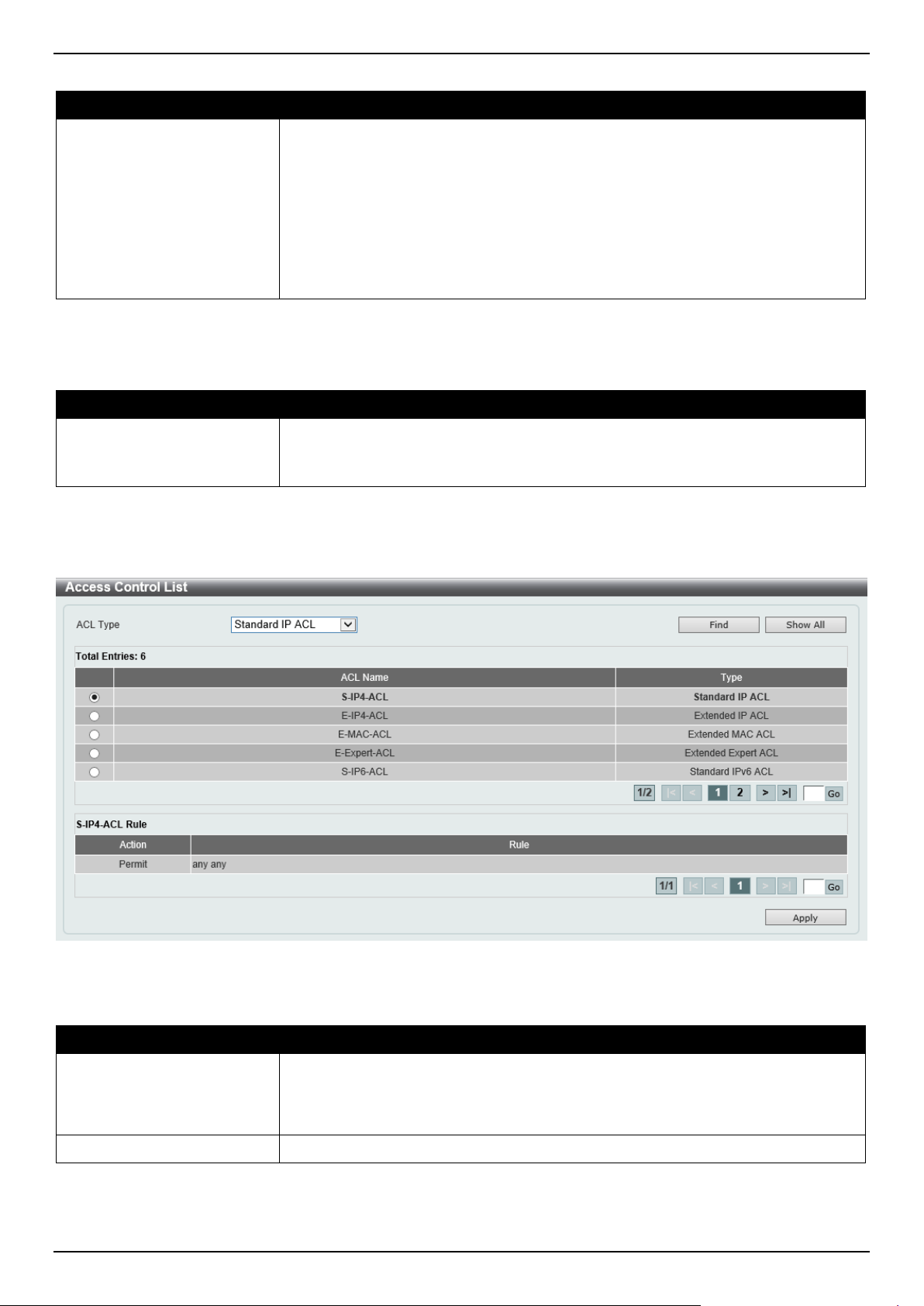
DGS-1520 Series Gigabit Ethernet Smart Managed Switch Web UI Reference Guide
301
The fields that can be configured in Register Suppression Time are described below:
Parameter Description
Register Suppression
Enter the register suppression timeout value here. The range is from 3 to 65535
seconds. When a DR receives the register stop message, it will start the
suppression timer. During the suppression period, a DR stops sending the register
message to the RP.
Use this feature on the first hop router. The value of the register probe time must
be less than half the value of the register suppression time to prevent a possible
negative value in the setting of the register stop timer. The minimal value for the
register suppression time is 3. By default, this value is 60 seconds.
Select the Default option to use the default value.
Click the Apply button to accept the changes made.
The fields that can be configured in Register Keepalive Time are described below:
Parameter Description
Register Keepalive
Enter the register keep-alive time value here. The range from 1 to 65525 seconds.
By default, this value is 185 seconds.
Select the Default option to use the default value.
Click the Apply button to accept the changes made.
After clicking the Show List button, the following page will appear.
Figure 6-97 PIM Register Settings (Show List) Window
The fields that can be configured are described below:
Parameter Description
ACL Type
Select the ACL type that will be used to display the type of existing access lists in
the table here. Options to choose from are Standard IP ACL, Extended IP ACL,
Standard IPv6 ACL, Extended IPv6 ACL, Extended MAC ACL, and Extended
Expert ACL.
ACL List
Select the radio button of the access list in the table that will be used here.
Click the Find button to display a list of access lists based on the selection made.
Click the Show All button to display all configured access lists.
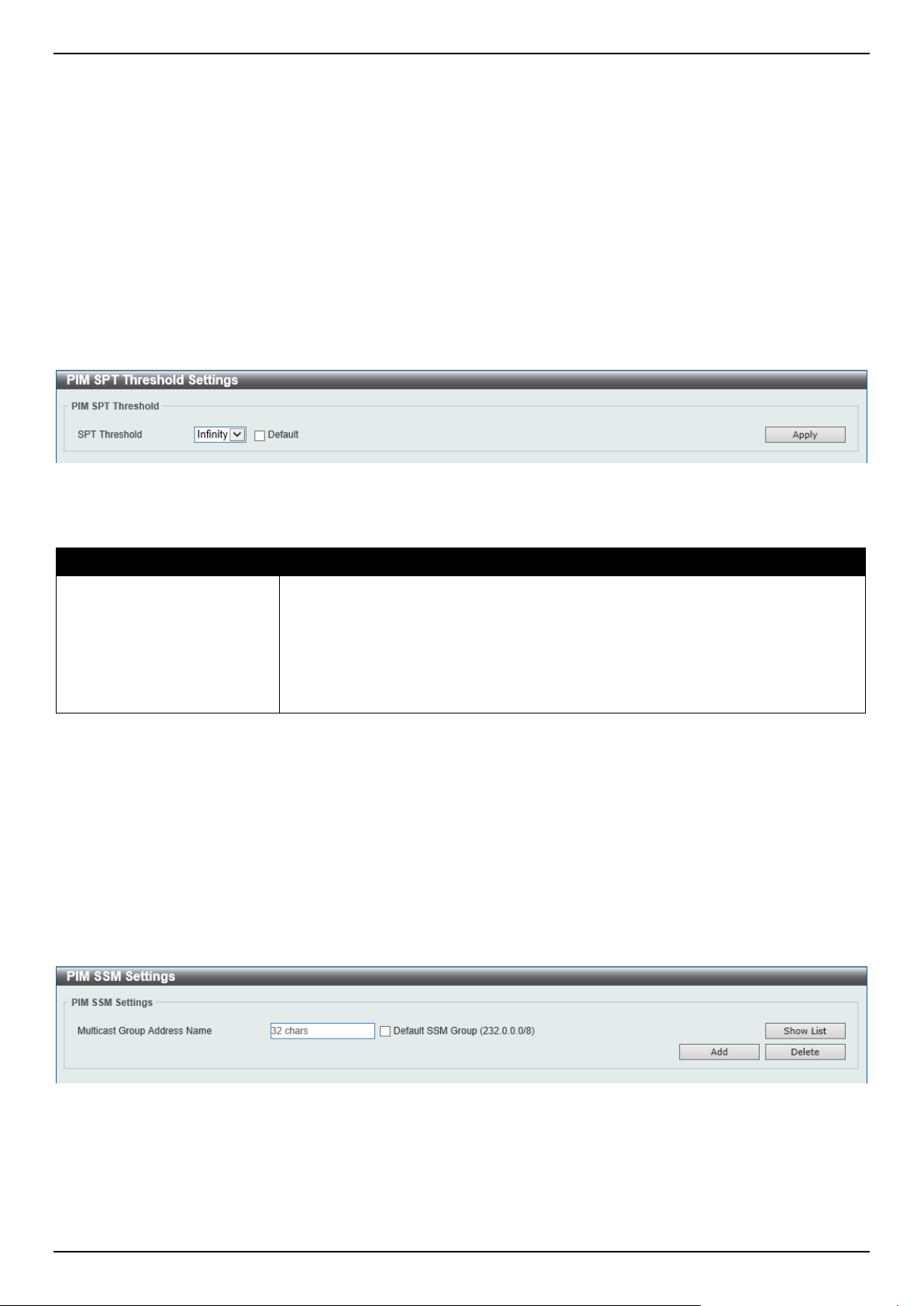
DGS-1520 Series Gigabit Ethernet Smart Managed Switch Web UI Reference Guide
302
Enter a page number and click the Go button to navigate to a specific page when multiple pages exist.
Click the Apply button to use the selected access list.
PIM SPT Threshold Settings
This window is used to display and configure the PIM SPT threshold settings. Use this feature on the last hop of the
router. In the PIM-SM mode, initially the multicast traffic from the source will be flowing along the RPT share tree to
the receiver. After the first packet arrives at the last hop router, for each group of traffic, it can operate in one of the
following two modes. With the mode Infinity, the traffic keeps following the share tree. With the mode 0, the source
tree will be established and the traffic Switchover to the source tree.
To view the following window, click L3 Features > IP Multicast Routing Protocol > PIM > PIM for IPv4 > PIM SPT
Threshold Settings, as shown below:
Figure 6-98 PIM SPT Threshold Settings Window
The fields that can be configured are described below:
Parameter Description
SPT Threshold
Select the SPT threshold option here. Options to choose from are:
• Infinity - Specifies to always rely on the shared tree.
• 0 - Specifies to establish the source tree right at the arrival of the first
packet.
By default, the Infinity option is used.
Select the Default option to use the default setting.
Click the Apply button to accept the changes made.
PIM SSM Settings
This window is used to display and configure the PIM SSM settings. Use this feature on the last hop of the router only.
When SSM is enabled, the last hop router will initiate to establish a source-based tree for the channel (S,G) on
receiving a IGMPv3 include (S, G) request that falls in the SSM range from the attached hosts.
To view the following window, click L3 Features > IP Multicast Routing Protocol > PIM > PIM for IPv4 > PIM SSM
Settings, as shown below:
Figure 6-99 PIM SSM Settings Window
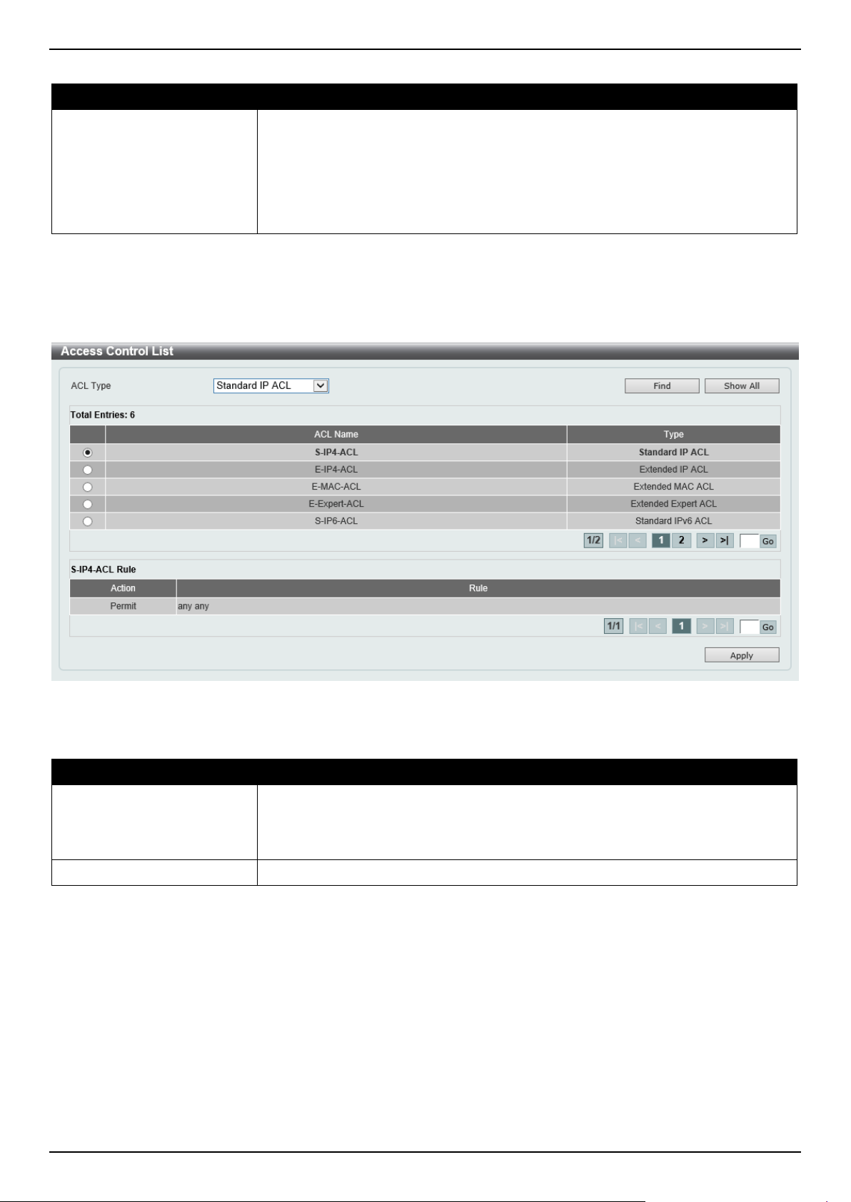
DGS-1520 Series Gigabit Ethernet Smart Managed Switch Web UI Reference Guide
303
The fields that can be configured are described below:
Parameter Description
Multicast Group Address
Name
Enter the standard IP access list name here that defines the user-specified SSM
group addresses. The group address should be defined in the destination IP
address field of the rule entry. Alternatively, click the Show List button to find and
select any of the exiting access lists configured on this Switch to be used in this
configuration. Selecting the Default SSM Group (232.0.0.0/8) option specifies to
use the default SSM group addresses. By default, the SSM group address range is
232/8.
Click the Add button to add a new entry based on the information entered.
Click the Delete button to delete an entry based on the information entered.
After clicking the Show List button, the following page will appear.
Figure 6-100 PIM SSM Settings (Show List) Window
The fields that can be configured are described below:
Parameter Description
ACL Type
Select the ACL type that will be used to display the type of existing access lists in
the table here. Options to choose from are Standard IP ACL, Extended IP ACL,
Standard IPv6 ACL, Extended IPv6 ACL, Extended MAC ACL, and Extended
Expert ACL.
ACL List
Select the radio button of the access list in the table that will be used here.
Click the Find button to display a list of access lists based on the selection made.
Click the Show All button to display all configured access lists.
Enter a page number and click the Go button to navigate to a specific page when multiple pages exist.
Click the Apply button to use the selected access list.
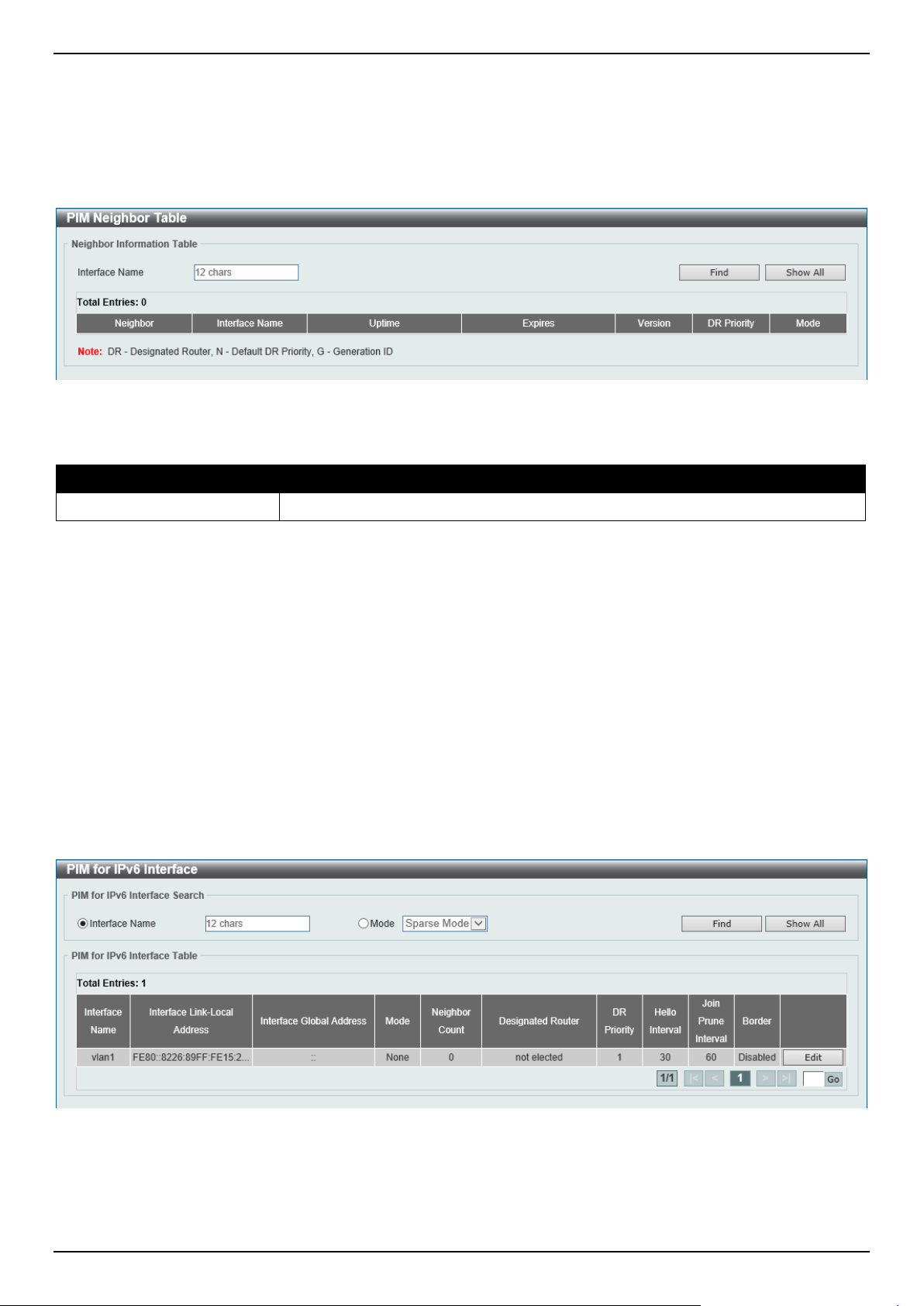
DGS-1520 Series Gigabit Ethernet Smart Managed Switch Web UI Reference Guide
304
PIM Neighbor Table
This window is used to find and display PIM neighbor information.
To view the following window, click L3 Features > IP Multicast Routing Protocol > PIM > PIM for IPv4 > PIM
Neighbor Table, as shown below:
Figure 6-101 PIM Neighbor Table Window
The fields that can be configured are described below:
Parameter Description
Interface Name
Enter the VLAN interface name here to display PIM-SM neighbor information.
Click the Find button to locate a specific entry based on the information entered.
Click the Show All button to display all the entries.
PIM for IPv6
In this section, the settings associated with PIM Sparse Mode for IPv6 (PIM-SMv6) and PIM Dense Mode for IPv6
(PIM-DMv6) will be configured.
PIM for IPv6 Interface
This window is used to display and configure the PIM IPv6 interface settings.
To view the following window, click L3 Features > IP Multicast Routing Protocol > PIM > PIM for IPv6 > PIM for
IPv6 Interface, as shown below:
Figure 6-102 PIM for IPv6 Interface Window
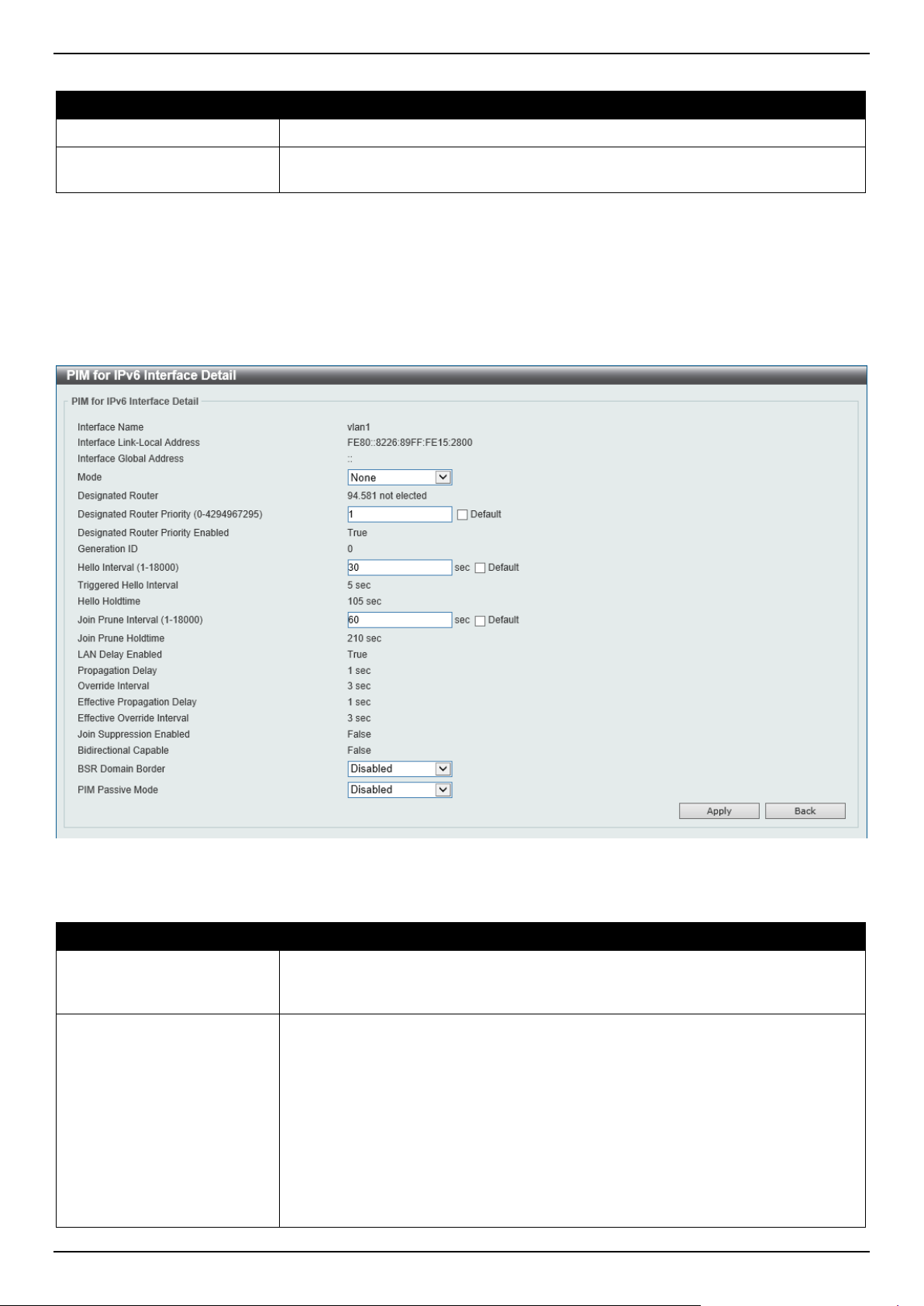
DGS-1520 Series Gigabit Ethernet Smart Managed Switch Web UI Reference Guide
305
The fields that can be configured are described below:
Parameter Description
Interface Name
Enter the VLAN interface name here.
Mode
Select the operation mode of IPv6 PIM entries used in this filtered search here.
Options to choose from are Sparse Mode and Dense Mode.
Click the Find button to locate a specific entry based on the information entered.
Click the Show All button to display all the entries.
Click the Edit button to modify the specified entry.
Enter a page number and click the Go button to navigate to a specific page when multiple pages exist.
After clicking the Edit button, the following page will appear.
Figure 6-103 PIM for IPv6 Interface (Edit) Window
The fields that can be configured are described below:
Parameter Description
Mode
Select the IPv6 PIM mode used in this interface here. Options to choose from are
None, Sparse Mode, and Dense Mode. PIM for IPv6 will be disabled in this
interface when the None option was selected.
Designated Router Priority
Enter the DR priority value here. The range is from 0 to 4294967295. A larger
value means a higher priority. This feature only takes effective when the VLAN
interface is PIM-SM mode enabled. When a DR is a candidate for election, the
following conditions apply:
• The router with the highest priority value configured on an interface will be
elected as the DR. If multiple routers have the same highest priority, then
the router with the highest IPv6 address configured on the interface will be
elected as the DR.
• If a router does not advertise a priority value in its hello messages, the
router is regarded as having the highest priority and will be elected as the
DR. If there are multiple routers do not include the DR priority option in their

DGS-1520 Series Gigabit Ethernet Smart Managed Switch Web UI Reference Guide
306
Parameter Description
hello messages, then the router with the highest IPv6 address will be
elected as the DR. By default, this value is 1.
Select the Default option to use the default value.
Hello Interval
Enter hello message interval value here. The range is from 1 to 18000 seconds. A
PIM router learns PIM neighbors via the hello message. Routers configured for IP
multicast send PIM hello messages to detect PIM routers. For SM, hello messages
are also used to determine which router will be elected as the designated router for
each LAN segment. By default, this value is 30 seconds.
Select the Default option to use the default value.
Join Prune Interval
Enter the Join/Prune message interval value here. The range is from 1 to 18000
seconds. When configuring the Join/Prune interval, the user needs to consider the
factors, such as configured bandwidth and expected average number of multicast
route entries for the attached network or link (for example, the period would be
longer for lower-speed links, or for routers in the center of the network that expect
to have a larger number of entries).
For SM-mode, the router will periodically send the join message based on this
interval. The hold-time in a Join/Prune message is 3.5 times the join-prune-
interval. The receiving router will start a timer based on this hold-time, and prune
the interface if no join message is received on this interface.
By default, this value is 60 seconds.
Select the Default option to use the default value.
BSR Domain Border
Select to enable or disable the BSR domain border feature here. When an
interface is configured as a border, it will prevent bootstrap router (BSR) messages
from being sent or received through it.
PIM Passive Mode
Select to enable or disable the PIM passive mode for this interface here. This
feature only takes effect when the interface is IPv6 PIM enabled. When the
passive mode is enabled, the interface will neither send PIM messages out nor
accept PIM messages from this interface. The router will act as it is the only PIM
router on the network. Use this feature only when there is only one PIM router on
the LAN.
Click the Apply button to accept the changes made.
Click the Back button to return to the previous window.
PIM for IPv6 BSR Candidate Settings
This window is used to display and configure the IPv6 PIM BSR candidate settings. This feature only affects PIM-SM
operation. This will cause the router to send bootstrap messages to all its PIM neighbors, with the address of the
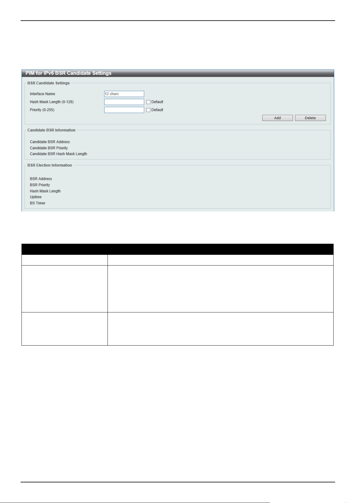
DGS-1520 Series Gigabit Ethernet Smart Managed Switch Web UI Reference Guide
307
designated interface as the BSR address. A PIM-SM domain must contain a unique BSR (Bootstrap Router) which is
responsible for collect and advertise the RP information.
To view the following window, click L3 Features > IP Multicast Routing Protocol > PIM > PIM for IPv6 > PIM for
IPv6 BSR Candidate Settings, as shown below:
Figure 6-104 PIM for IPv6 BSR Candidate Settings Window
The fields that can be configured are described below:
Parameter Description
Interface Name
Enter the VLAN interface name used here.
Hash Mask Length
Enter the hash mask length for RP selection here. The range is from 0 to 128. The
mask (128 bits maximum) that is to be logically AND with the group address before
the hash function is executed. All groups with the same seed hash (correspond) to
the same RP. Therefore, one RP can be derived for multiple groups. By default,
this value is 126.
Select the Default option to use the default value.
Priority
Enter the priority value for the BSR candidate here. The range is from 0 to 255.
The BSR with the larger priority is preferred. If the priority values are the same, the
router with the larger IPv6 address is the BSR. By default, this value is 64.
Select the Default option to use the default value.
Click the Add button to add a new entry based on the information entered.
Click the Delete button to delete an entry based on the information entered.

DGS-1520 Series Gigabit Ethernet Smart Managed Switch Web UI Reference Guide
308
PIM for IPv6 BSR Table
This window is used to view IPv6 PIM BSR information.
To view the following window, click L3 Features > IP Multicast Routing Protocol > PIM > PIM for IPv6 > PIM for
IPv6 BSR Table, as shown below:
Figure 6-105 PIM for IPv6 BSR Table Window
PIM for IPv6 RP Address
This window is used to display and configure the IPv6 PIM RP address settings. This feature only affects PIM-SM
operation. Use this feature to statically define the RP address for multicast groups that are to operate in sparse mode.
Use a single RP for more than one group. The conditions specified by the access list determine for which groups the
RP can be used. Multiple RP can be defined, each with a single access list. The new setting overrides the old one.
All routers in a domain should have a consistent multicast group to RP mapping. The first hop router that initiates a
register message will use the mapping entries to determine the RP for sending the PIM register message destined for
a specific group. The last hop router that initiates a join message uses the mapping entries to determine the RP for
sending the join and prune message for a specific group. When a router receives a join message, it will check the
mapping entries for forwarding of the message. When a RP receives a register message, if the router is not the right
RP for the multicast group, a register-stop message will be sent.
If the PIM domain is using embedded-RP, only the RP needs to be statically configured as the RP for the embedded
RP ranges. The other routers will discover the RP address from the IPv6 group address. If these routers want to select
a static RP instead of the embedded RP, the specific embedded RP group range must be configured in the access list
of the static RP.
To view the following window, click L3 Features > IP Multicast Routing Protocol > PIM > PIM for IPv6 > PIM for
IPv6 RP Address, as shown below:
Figure 6-106 PIM for IPv6 RP Address Window
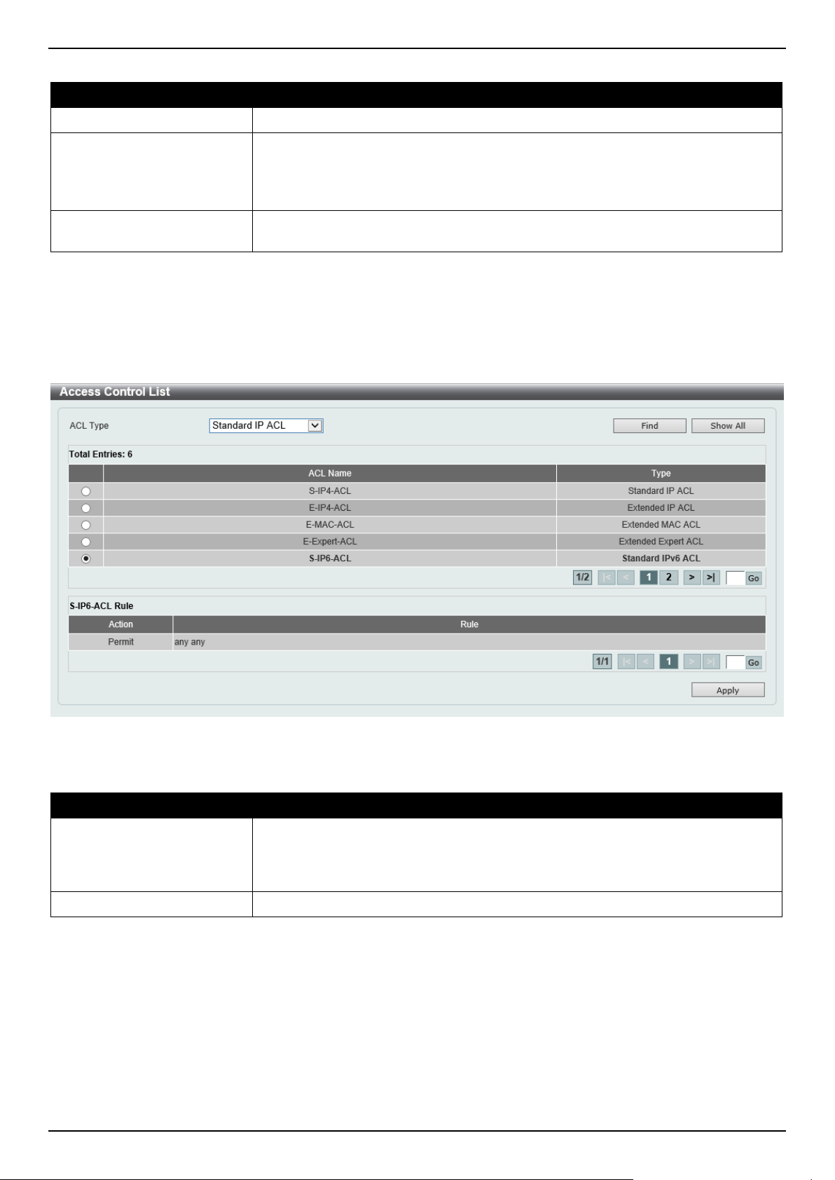
DGS-1520 Series Gigabit Ethernet Smart Managed Switch Web UI Reference Guide
309
The fields that can be configured are described below:
Parameter Description
RP Address
Enter the RP IPv6 address here.
Group Access List Name
Enter the standard IPv6 access list that will be used here. Alternatively, click the
Show List button to find and select any of the exiting access lists configured on
this Switch to be used in this configuration.
Select the All Groups option to map the RP to all multicast groups.
Override
Selecting this option specifies that the static RP will override dynamically learned
RPs.
Click the Add button to add a new entry based on the information entered.
Click the Delete button to delete an entry based on the information entered.
Enter a page number and click the Go button to navigate to a specific page when multiple pages exist.
After clicking the Show List button, the following page will appear.
Figure 6-107 PIM for IPv6 RP Address (Show List) Window
The fields that can be configured are described below:
Parameter Description
ACL Type
Select the ACL type that will be used to display the type of existing access lists in
the table here. Options to choose from are Standard IP ACL, Extended IP ACL,
Standard IPv6 ACL, Extended IPv6 ACL, Extended MAC ACL, and Extended
Expert ACL.
ACL List
Select the radio button of the access list in the table that will be used here.
Click the Find button to display a list of access lists based on the selection made.
Click the Show All button to display all configured access lists.
Enter a page number and click the Go button to navigate to a specific page when multiple pages exist.
Click the Apply button to use the selected access list.
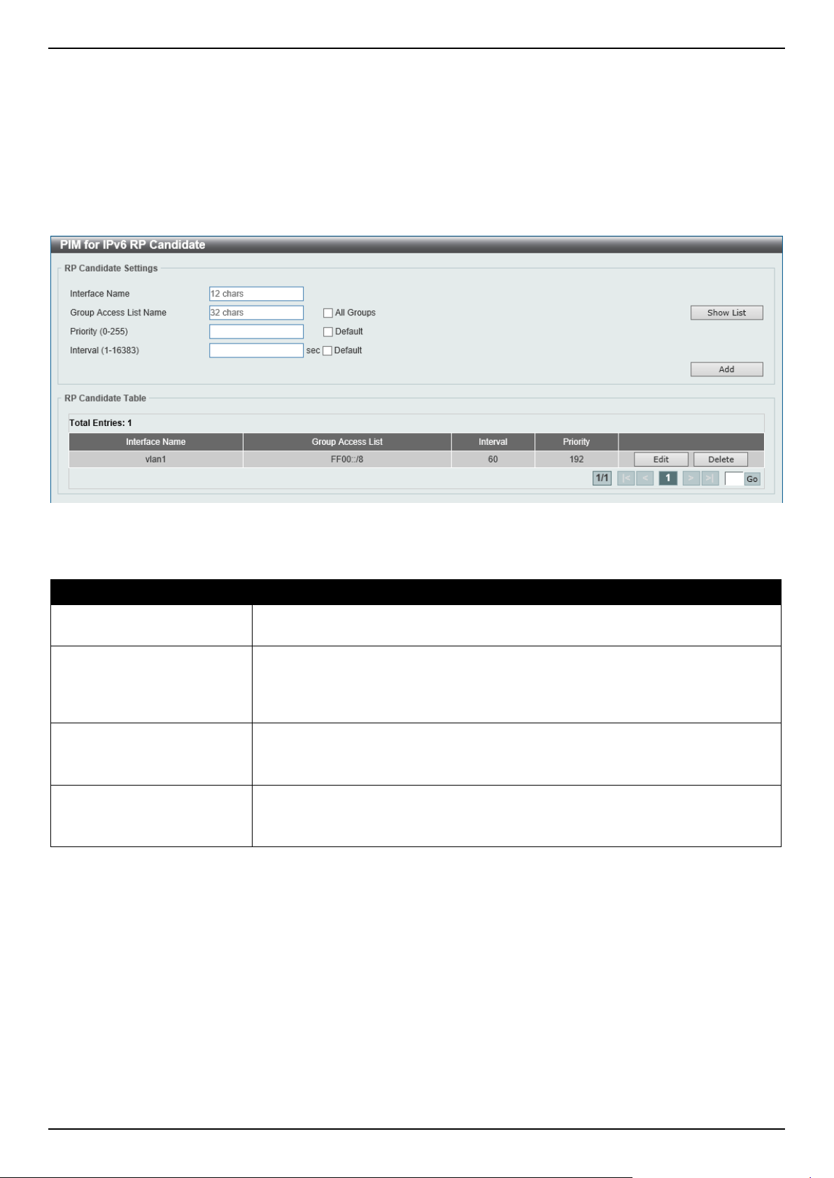
DGS-1520 Series Gigabit Ethernet Smart Managed Switch Web UI Reference Guide
310
PIM for IPv6 RP Candidate
This window is used to display and configure the IPv6 PIM RP candidate settings. Only one group access list can be
specified for each interface. The latest configuration overrides the previous one. This feature can be issued multiple
times for different interfaces. This configuration causes the router to send a PIMv2 message advertising itself as a
candidate RP to the BSR.
To view the following window, click L3 Features > IP Multicast Routing Protocol > PIM > PIM for IPv6 > PIM for
IPv6 RP Candidate, as shown below:
Figure 6-108 PIM for IPv6 RP Candidate Window
The fields that can be configured are described below:
Parameter Description
Interface Name
Enter the interface name here whose IPv6 address will be advertised as the
candidate RP (C-RP).
Group Access List Name
Enter the standard IPv6 access list that will be used here. Alternatively, click the
Show List button to find and select any of the exiting access lists configured on
this Switch to be used in this configuration.
Select the All Groups option to map the candidate RP to all multicast groups.
Priority
Enter the RP priority value here. The range is from 0 to 255. By default, this value
is 192.
Select the Default option to use the default value.
Interval
Enter the RP candidate advertisement interval value here. The range is from 1 to
16383 seconds. By default, this value is 60 seconds.
Select the Default option to use the default value.
Click the Add button to add a new entry based on the information entered.
Click the Edit button to modify the specified entry.
Click the Delete button to delete the specified entry.
Enter a page number and click the Go button to navigate to a specific page when multiple pages exist.
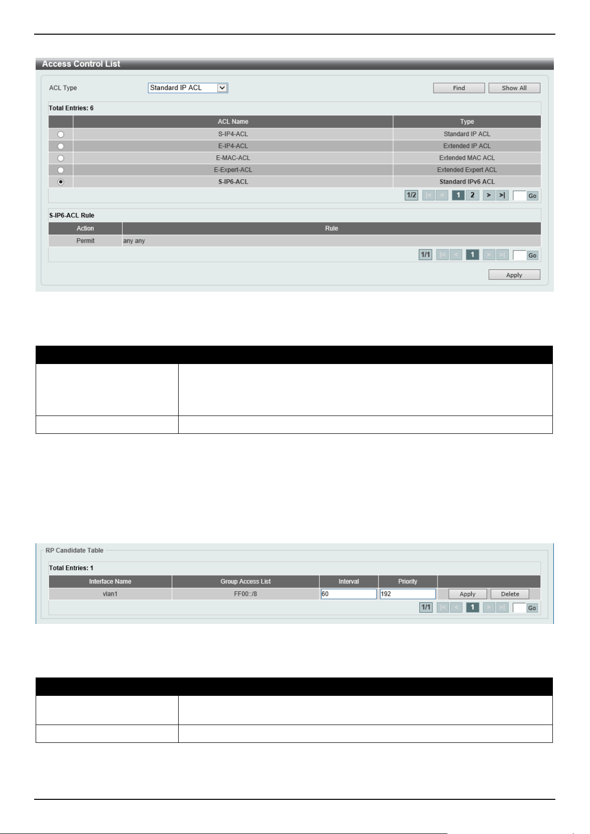
DGS-1520 Series Gigabit Ethernet Smart Managed Switch Web UI Reference Guide
311
After clicking the Show List button, the following page will appear.
Figure 6-109 PIM for IPv6 RP Candidate (Show List) Window
The fields that can be configured are described below:
Parameter Description
ACL Type
Select the ACL type that will be used to display the type of existing access lists in
the table here. Options to choose from are Standard IP ACL, Extended IP ACL,
Standard IPv6 ACL, Extended IPv6 ACL, Extended MAC ACL, and Extended
Expert ACL.
ACL List
Select the radio button of the access list in the table that will be used here.
Click the Find button to display a list of access lists based on the selection made.
Click the Show All button to display all configured access lists.
Enter a page number and click the Go button to navigate to a specific page when multiple pages exist.
Click the Apply button to use the selected access list.
After clicking the Edit button, the following page will appear.
Figure 6-110 PIM for IPv6 RP Candidate (Edit) Window
The additional fields that can be configured are described below:
Parameter Description
Interval
Enter the RP candidate advertisement interval value here. The range is from 1 to
16383 seconds.
Priority
Enter the RP priority value here. The range is from 0 to 255.
Click the Apply button to accept the changes made.
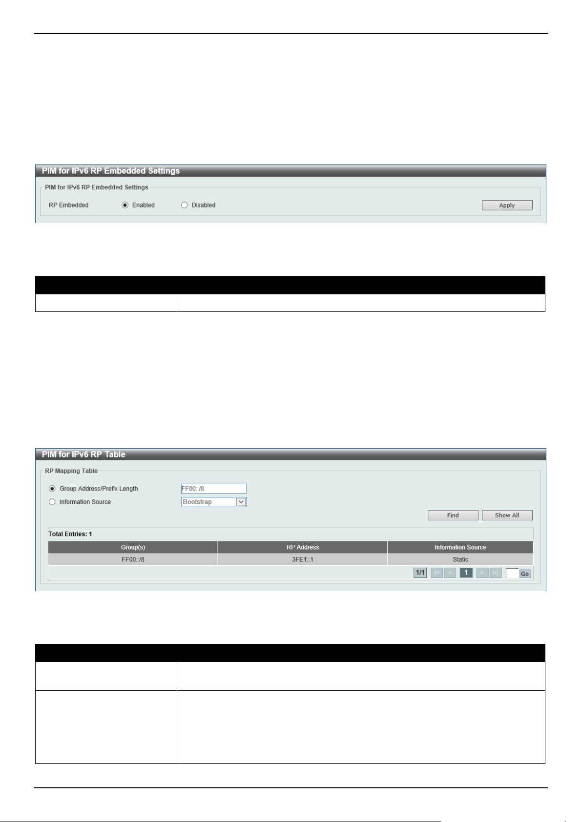
DGS-1520 Series Gigabit Ethernet Smart Managed Switch Web UI Reference Guide
312
PIM for IPv6 RP Embedded Settings
This window view and configure the IPv6 PIM embedded settings. Embedded RP defines an address allocation policy
in which the address of the RP is encoded in an IPv6 multicast group address. This allows an easy deployment of
scalable inter-domain multicast and simplifies the intra-domain multicast configuration as well. IPv6 Multicast group
addresses embedded with RP information start with ff70::/12 where the flag value of 7 means embedded RP.
To view the following window, click L3 Features > IP Multicast Routing Protocol > PIM > PIM for IPv6 > PIM for
IPv6 RP Embedded Settings, as shown below:
Figure 6-111 PIM for IPv6 RP Embedded Settings Window
The fields that can be configured are described below:
Parameter Description
RP Embedded
Select to enable or disable the RP embedded feature here.
Click the Apply button to accept the changes made.
PIM for IPv6 RP Table
This window is used to find and display IPv6 PIM RP information.
To view the following window, click L3 Features > IP Multicast Routing Protocol > PIM > PIM for IPv6 > PIM for
IPv6 RP Table, as shown below:
Figure 6-112 PIM for IPv6 RP Table Window
The fields that can be configured are described below:
Parameter Description
Group Address/Prefix
Length
Enter the multicast group IPv6 address and prefix length here.
Source
Select the source to display here. Options to choose from are:
• Bootstrap - Specifies to display ranges learned through the BSR.
• Embedded RP - Specifies to display group ranges learned through the
embedded rendezvous point (RP).
• Static - Specifies to display ranges enabled by static configuration.
Click the Find button to locate a specific entry based on the information entered.
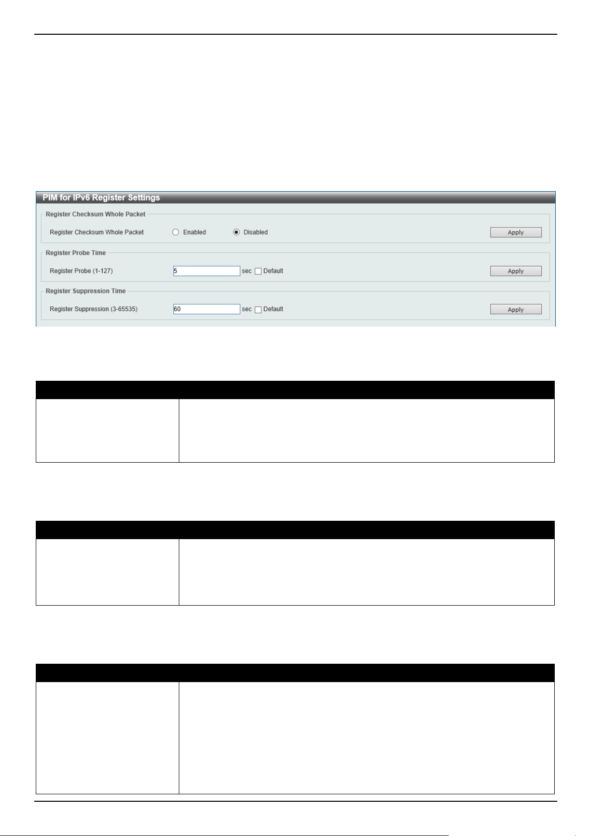
DGS-1520 Series Gigabit Ethernet Smart Managed Switch Web UI Reference Guide
313
Click the Show All button to display all the entries.
Enter a page number and click the Go button to navigate to a specific page when multiple pages exist.
PIM for IPv6 Register Settings
This window is used to display and configure the IPv6 PIM register settings.
To view the following window, click L3 Features > IP Multicast Routing Protocol > PIM > PIM for IPv6 > PIM for
IPv6 Register Settings, as shown below:
Figure 6-113 PIM for IPv6 Register Settings Window
The fields that can be configured in Register Checksum Whole Packet are described below:
Parameter Description
Register Checksum Whole
Packet
Select the enable or disable the register checksum whole-packet feature here.
When enabled, it configures the router to calculate the checksum of register
message over the entire PIM message including the data portion. By default, the
register checksum methodology is PIM RFC-compliant, excluding the data portion
in the Register message.
Click the Apply button to accept the changes made.
The fields that can be configured in Register Probe Time are described below:
Parameter Description
Register Probe
Enter the register probe time value here. The range is from 1 to 127 seconds. The
register-probe time is the time before the Register-Stop Timer (RST) expires when
a DR may send a Null-Register to the RP to cause it to resend a Register-Stop
message. By default, this value is 5 seconds.
Select the Default option to use the default value.
Click the Apply button to accept the changes made.
The fields that can be configured in Register Suppression Time are described below:
Parameter Description
Register Suppression
Enter the register suppression timeout value here. The range is from 3 to 65535
seconds. When a DR receives the register-stop message, it will start the
suppression timer. During the suppression time, a DR will stop sending Register-
encapsulated data to the RP. This timer should be configured on the designated
router. The value of the Register Probe Time must be less than half the value of
the Register Suppression Time to prevent a possible negative value in the setting
of the Register-Stop Timer. The minimal value for Register Suppression Time is 3.
By default, this value is 60 seconds.
Select the Default option to use the default value.
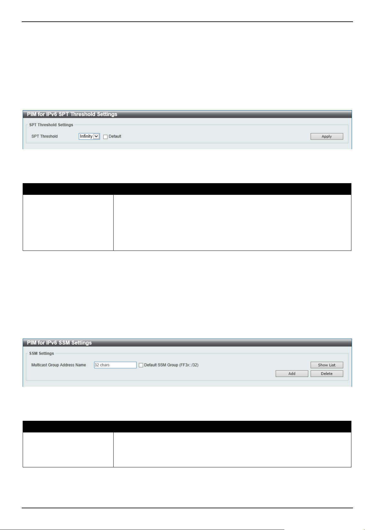
DGS-1520 Series Gigabit Ethernet Smart Managed Switch Web UI Reference Guide
314
Click the Apply button to accept the changes made.
PIM for IPv6 SPT Threshold Settings
This window is used to display and configure the Shortest Path Tree (SPT) threshold settings.
To view the following window, click L3 Features > IP Multicast Routing Protocol > PIM > PIM for IPv6 > PIM for
IPv6 SPT Threshold Settings, as shown below:
Figure 6-114 SPT Threshold Settings Window
The fields that can be configured are described below:
Parameter Description
SPT Threshold
Select the SPT threshold value here. Options to choose from are:
• Infinity - Specifies to always rely on the shared tree.
• 0 - Specifies to establish the source tree right at the arrival of the first
packet.
By default, the Infinity option is used.
Select the Default option to use the default setting.
Click the Apply button to accept the changes made.
PIM for IPv6 SSM Settings
This window is used to display and configure the IPv6 PIM SSM settings.
To view the following window, click L3 Features > IP Multicast Routing Protocol > PIM > PIM for IPv6 > PIM for
IPv6 SSM Settings, as shown below:
Figure 6-115 PIM for IPv6 SSM Settings Window
The fields that can be configured are described below:
Parameter Description
Multicast Group Address
Name
Enter the name of the access list that defines the user-specified SSM group
address here.
Select the Default SSM Group option to use the default SSM group address
range. By default, the SSM group address range is FF3x::/32.
Click the Add button to add a new entry based on the information entered.
Click the Delete button to delete an entry based on the information entered.
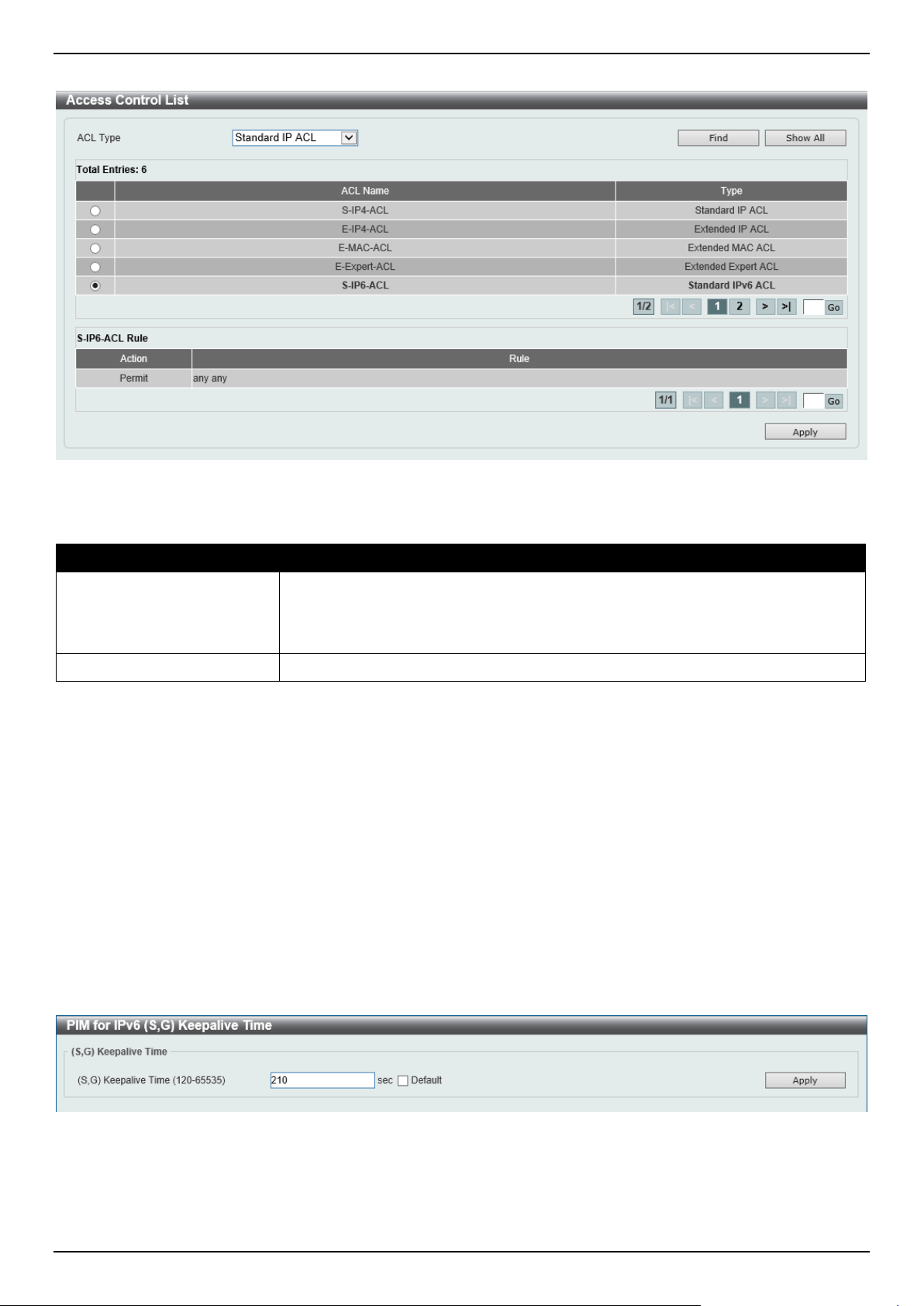
DGS-1520 Series Gigabit Ethernet Smart Managed Switch Web UI Reference Guide
315
After clicking the Show List button, the following page will appear.
Figure 6-116 PIM for IPv6 SSM Settings (Show List) Window
The fields that can be configured are described below:
Parameter Description
ACL Type
Select the ACL type that will be used to display the type of existing access lists in
the table here. Options to choose from are Standard IP ACL, Extended IP ACL,
Standard IPv6 ACL, Extended IPv6 ACL, Extended MAC ACL, and Extended
Expert ACL.
ACL List
Select the radio button of the access list in the table that will be used here.
Click the Find button to display a list of access lists based on the selection made.
Click the Show All button to display all configured access lists.
Enter a page number and click the Go button to navigate to a specific page when multiple pages exist.
Click the Apply button to use the selected access list.
PIM for IPv6 (S,G) Keepalive Time
This window is used to display and configure the IPv6 PIM (S,G) keep-alive time settings. This feature is used to
configure the keep-alive timer, which is the period during which the PIM router will maintain the (S, G) state in the
absence of explicit (S, G) local membership or (S, G) join messages received to maintain it.
To view the following window, click L3 Features > IP Multicast Routing Protocol > PIM > PIM for IPv6 > PIM for
IPv6 (S,G) Keepalive Time, as shown below:
Figure 6-117 PIM for IPv6 (S,G) Keepalive Time Window
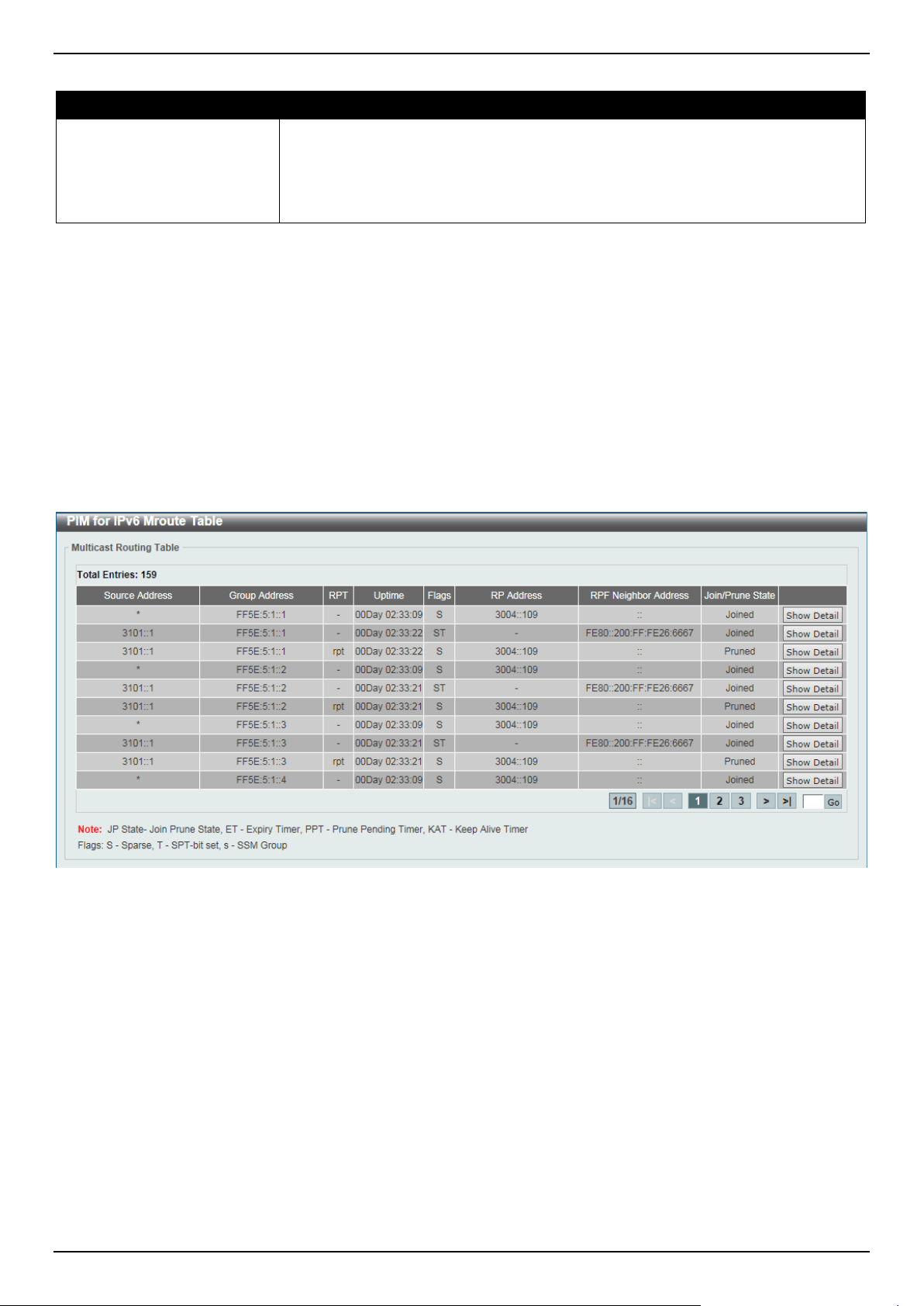
DGS-1520 Series Gigabit Ethernet Smart Managed Switch Web UI Reference Guide
316
The fields that can be configured are described below:
Parameter Description
(S,G) Keepalive Time
Enter the (S,G) keep-alive time value here. This specifies the period during which
the PIM router will maintain the (S, G) state in the absence of explicit (S, G) local
membership or (S, G) join messages received to maintain it. The range is from 120
to 65535 seconds. By default, this value is 210 seconds.
Select the Default option to use the default value.
Click the Apply button to accept the changes made.
PIM for IPv6 Multicast Route Table
This window is used to display all entries in the IPv6 multicast routing table. The Switch populates the multicast
routing table by creating source, group (S,G) entries from star, group (*,G) entries. The star (*) refers to all source
addresses, the "S" refers to a single source address, and the "G" is the destination multicast group address. In
creating (S,G) entries, the software uses the best path to that destination group found in the unicast routing table,
through Reverse Path Forwarding (RPF).
To view the following window, click L3 Features > IP Multicast Routing Protocol > PIM > PIM for IPv6 > PIM for
IPv6 Multicast Route Table, as shown below:
Figure 6-118 PIM for IPv6 Multicast Route Table Window
Click the Show Detail button to view detailed information for the specified entry.
Enter a page number and click the Go button to navigate to a specific page when multiple pages exist.
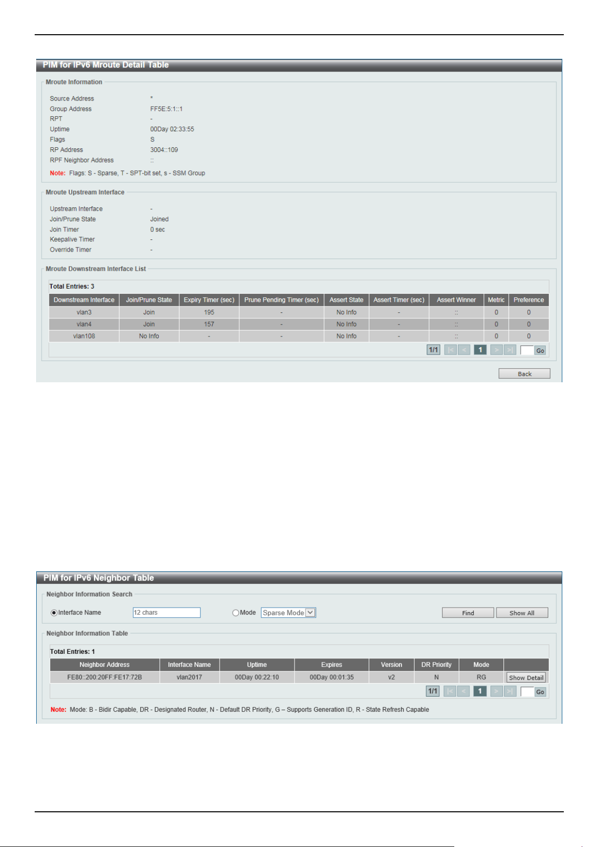
DGS-1520 Series Gigabit Ethernet Smart Managed Switch Web UI Reference Guide
317
After clicking the Show Detail button, the following page will appear.
Figure 6-119 PIM for IPv6 Multicast Route Table (Show Detail) Window
Enter a page number and click the Go button to navigate to a specific page when multiple pages exist.
Click the Back button to return to the previous window.
PIM for IPv6 Neighbor Table
This window is used to display IPv6 PIM neighbor information.
To view the following window, click L3 Features > IP Multicast Routing Protocol > PIM > PIM for IPv6 > PIM for
IPv6 Neighbor Table, as shown below:
Figure 6-120 PIM for IPv6 Neighbor Table Window
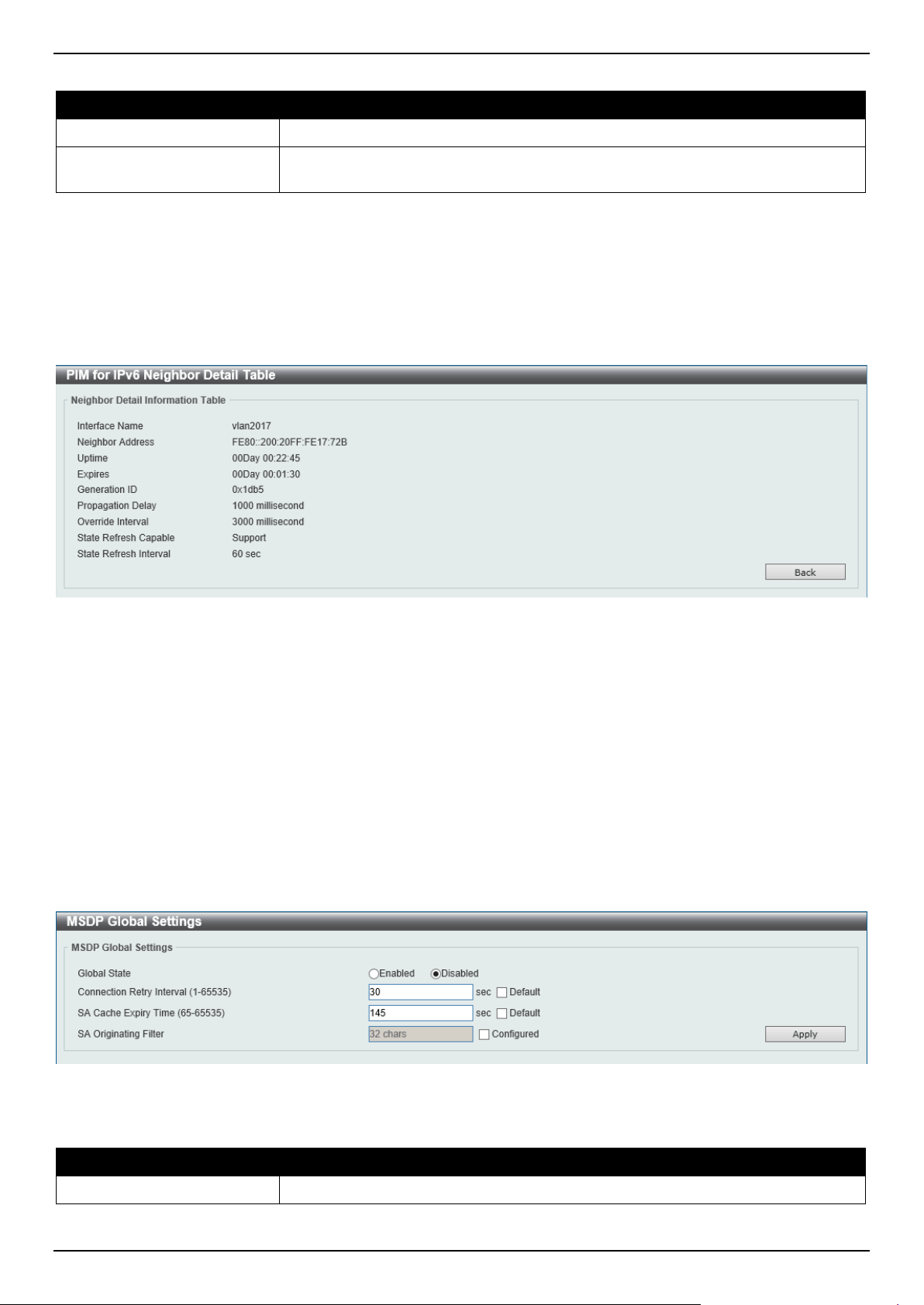
DGS-1520 Series Gigabit Ethernet Smart Managed Switch Web UI Reference Guide
318
The fields that can be configured are described below:
Parameter Description
Interface Name
Enter the VLAN interface name used in this display here.
Mode
Select the operation mode of IPv6 PIM entries used in this filtered search here.
Options to choose from are Sparse Mode and Dense Mode.
Click the Find button to locate a specific entry based on the information entered.
Click the Show All button to display all the entries.
Click the Show Detail button to view detailed information for the specified entry.
Enter a page number and click the Go button to navigate to a specific page when multiple pages exist.
After clicking the Show Detail button, the following page will appear.
Figure 6-121 PIM for IPv6 Neighbor Table (Show Detail) Window
Click the Back button to return to the previous window.
MSDP
MSDP Global Settings
This window is used to display and configure the global Multicast Source Discovery Protocol (MSDP) settings.
To view the following window, click L3 Features > IP Multicast Routing Protocol > PIM > MSDP > MSDP Global
Settings, as shown below:
Figure 6-122 MSDP Global Settings Window
The fields that can be configured are described below:
Parameter Description
Global State
Select to globally enable or disable the MSDP feature here.
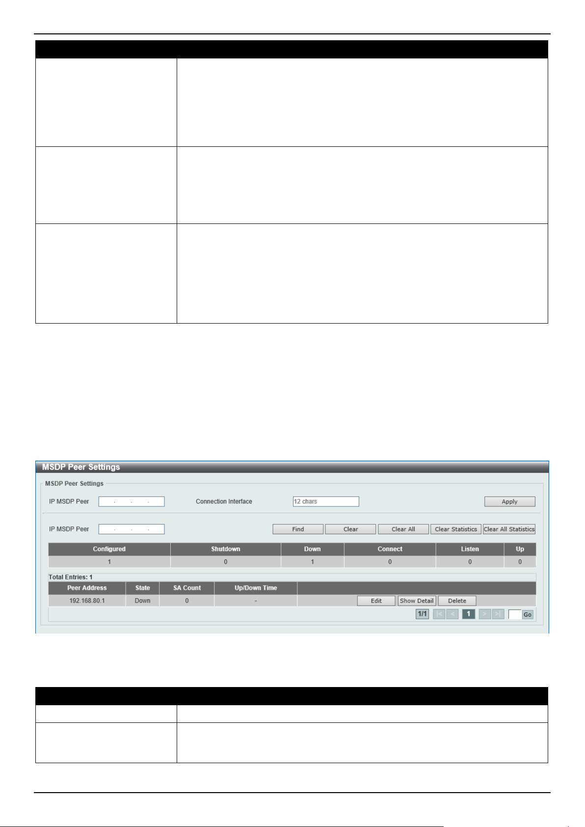
DGS-1520 Series Gigabit Ethernet Smart Managed Switch Web UI Reference Guide
319
Parameter Description
Connect Retry Interval
Enter the connect retry interval time value here. The range is from 1 to 65535
seconds. This is used to configure the interval at which MSDP peers will wait after
peering sessions are reset before attempting to re-establish. A larger time interval
will delay the time before attempting to re-establish the peer session. For best
results, configure the value in the range from 1 to 60 seconds. By default, this
value is 30 seconds.
Select the Default option to use the default value.
SA Cache Expiry Time
Enter the Source-Active (SA) cache expiry time value here. The range is from 65
to 65535 seconds. This is used to configure the expiry time for SA cache entries.
The interval for SA originating is 60 seconds and it cannot be modified, so the SA
cache expiry time allows for the tuning of expected packet loss on a network
implicitly.
Select the Default option to use the default value.
SA Originating Filter Select the Configured option and enter the SA originating filter string here. This
string can be up to 32 characters long. An RP is configured to run MSDP and will
originate SA messages for all local sources that register with this RP. By
configuring the filter with a list, an RP will only originate SA messages for local
sources by sending to specified groups that match (S, G) pairs defined in standard
IP access list.
By selecting the Configured option and not specifying the filter string, an RP from
originating SA messages for all local sources can be prevented.
Click the Apply button to accept the changes made.
MSDP Peer Settings
This window is used to display and configure the MSDP peer settings.
To view the following window, click L3 Features > IP Multicast Routing Protocol > PIM > MSDP > MSDP Peer
Settings, as shown below:
Figure 6-123 MSDP Peer Settings Window
The fields that can be configured are described below:
Parameter Description
IP MSDP Peer
Enter the MSDP peer IP address here.
Connection Interface
Enter the connect interface name here. This string can be up to 12 characters
long. This specifies the local interface that is used as the source IP address for
TCP connections.
Click the Apply button to accept the changes made.
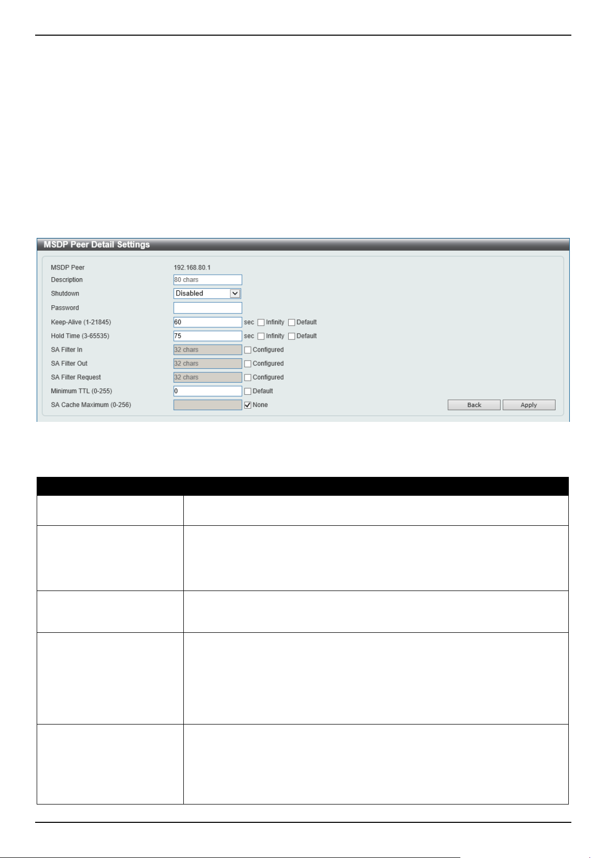
DGS-1520 Series Gigabit Ethernet Smart Managed Switch Web UI Reference Guide
320
Click the Find button to find and display an entry based on the information entered.
Click the Clear button to clear the entries from the table based on the information entered.
Click the Clear All button to clear all the entries from the table.
Click the Clear Statistics button to clear the statistics information of the entries based on the information entered.
Click the Clear All Statistics button to clear all the statistics information displayed in the table.
Click the Edit button to re-configure the specific entry.
Click the Show Detail button to display detailed information about the specified entry.
Click the Delete button to delete the specified entry.
Enter a page number and click the Go button to navigate to a specific page when multiple pages exist.
After clicking the Edit button, the following page will appear.
Figure 6-124 MSDP Peer Settings (Edit) Window
The fields that can be configured are described below:
Parameter Description
Description
Enter the description for the MSDP peer here. This string can be up to 80
characters long.
Shutdown
Select to enable or disable the shutdown feature here. The shutdown state must
be configured on an existing MSDP peer. If the MSDP peer is in the shutdown
state, the TCP connection between two peers won't be established. If the MSDP
peer was changed into the no shutdown state, the TCP connection between two
peers will attempt to re-establish.
Password
Enter the MD5 password for a TCP connection between two peers here. MD5
authentication must be configured with the same password on both MSDP peers.
Otherwise, the connection between them cannot be established.
Keep-Alive
Enter the keep-alive time value here. The range is from 1 to 21845 seconds. The
keep-alive interval should be less than the hold time configured on the remote side
of the MSDP TCP connection. Otherwise, the remote side of MSDP TCP
connection may be disconnected before receiving the MSDP keep-alive message.
Selecting the Infinity option specifies the MSDP peer to never send keep-alive
messages. By default, this value is 60 seconds.
Select the Default option to use the default value.
Hold Time
Enter the hold-time value here. The range is from 3 to 65535 seconds. The hold
time interval must be larger than keep-alive time configured on the remote side of
the MSDP TCP connection. Otherwise, the MSDP TCP connection may be
disconnected before receiving the MSDP keep-alive message.
Select the Infinity option to specify that the connection between two peers is never
torn down.

DGS-1520 Series Gigabit Ethernet Smart Managed Switch Web UI Reference Guide
321
Parameter Description
Select the Default option to use the default value.
SA Filter In Select the Configured option and enter the SA filter-in string here. This string can
be up to 32 characters long. The router will receive all SA messages sent to it from
a specified peer. By not specifying this string, the router will ignore all SA
messages sent to it from a specified peer. By configuring this string, the router will
only receive incoming SA messages from a specified peer that matches the (S, G)
pairs defined in the standard IP access list.
SA Filter Out Select the Configured option and enter the SA filter-out string here. This string
can be up to 32 characters long. The router will forward all SA messages to an
MSDP peer. By not specifying this string, the router will stop forwarding SA
messages to a specified peer. By specifying this string, the router only forwards SA
messages that match (S, G) pairs defined in the standard IP access list to a
specified peer.
SA Filter Request Select the Configured option and enter the SA filter request string here. This
string can be up to 32 characters long. The router will process all SA request
messages from a specified peer. By not specifying this string, the router will stop
processing Source-Active request messages from a specified peer. By specifying
this string, the router only processes SA request messages that request groups
that are defined in the standard IP access list from a specified peer.
Minimum TTL
Enter the minimum TTL time value here. The range is from 0 to 225. When the SA
messages are sent from MSDP peers, If the Time-To-Live (TTL) value of multicast
data packets in SA message will be decreased, if the decreased TTL value is
smaller than minimum TTL value of the MSDP peer the SA message was sent to,
the SA will not be sent out. By default, this value is 0.
Select the Default option to use the default value.
SA Cache Maximum
Enter the maximum SA cache value here. The range is from 0 to 256. When the
maximum number of SA cache entries is configured to zero, the Switch cannot
learn a SA cache entry from the peer. When the maximum number of SA cache
entries is configured to be smaller than the existing SA cache entries, the older
existing SA cache entries will be removed until the number of SA cache entries is
equal to the maximum number.
Select the None option to specify that no limitation is applied for the number of
Source-Active cache entries.
Click the Back button to return to the previous window.
Click the Apply button to accept the changes made.
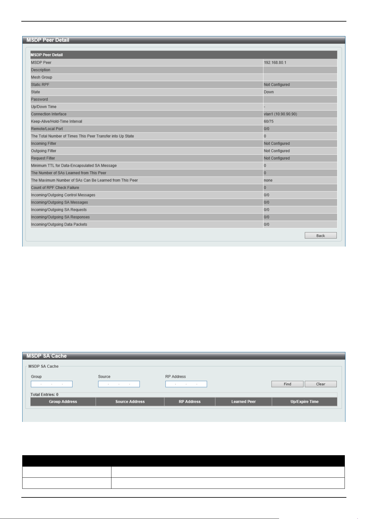
DGS-1520 Series Gigabit Ethernet Smart Managed Switch Web UI Reference Guide
322
After clicking the Show Detail button, the following page will appear.
Figure 6-125 MSDP Peer Settings (Show Detail) Window
Click the Back button to return to the previous window.
MSDP SA Cache
This window is used to view and clear the MSDP SA cache table.
To view the following window, click L3 Features > IP Multicast Routing Protocol > PIM > MSDP > MSDP SA
Cache, as shown below:
Figure 6-126 MSDP SA Cache Window
The fields that can be configured are described below:
Parameter Description
Group
Enter the group address that will be used here.
Source
Enter the source address that will be used here.
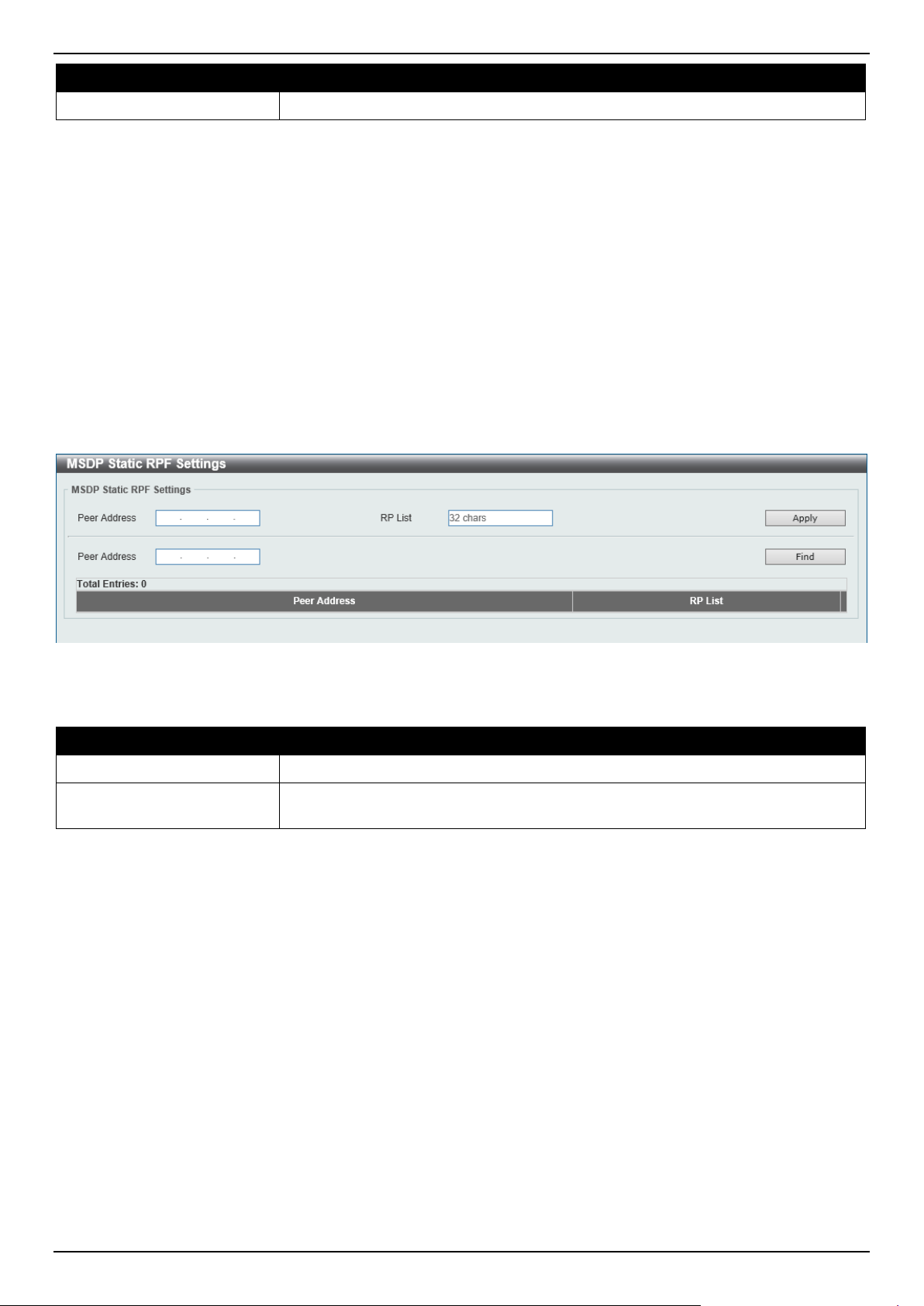
DGS-1520 Series Gigabit Ethernet Smart Managed Switch Web UI Reference Guide
323
Parameter Description
RP Address
Enter the RP address that will be used here.
Click the Find button to find and display an entry based on the information entered.
Click the Clear button to clear the entries from the table based on the information entered.
MSDP Static RPF Settings
This window is used to display and configure the MSDP static RPF settings. Before configuring a static RPF peer, an
MSDP peer must be added first. If the RP prefix list is specified, the peer will be a static RPF peer only for RPs in the
prefix list. When multiple static RPF peers are specified without an RP prefix list, only the connected peer whose
address is smallest will be the active static RPF peer. If an MSDP peer is configured as a static RPF peer multiple
times, only the last configuration takes effect. If there is one MSDP peer only, this MSDP peer works as a static RPF
peer.
To view the following window, click L3 Features > IP Multicast Routing Protocol > PIM > MSDP > MSDP Static
RPF Settings, as shown below:
Figure 6-127 MSDP Static RPF Settings Window
The fields that can be configured are described below:
Parameter Description
Peer Address
Enter the MSDP peer address here.
RP List
Enter the name of the standard IP access list that defines the RP prefix list here.
This string can be up to 32 characters long.
Click the Apply button to accept the changes made.
Click the Find button to find and display an entry based on the information entered.
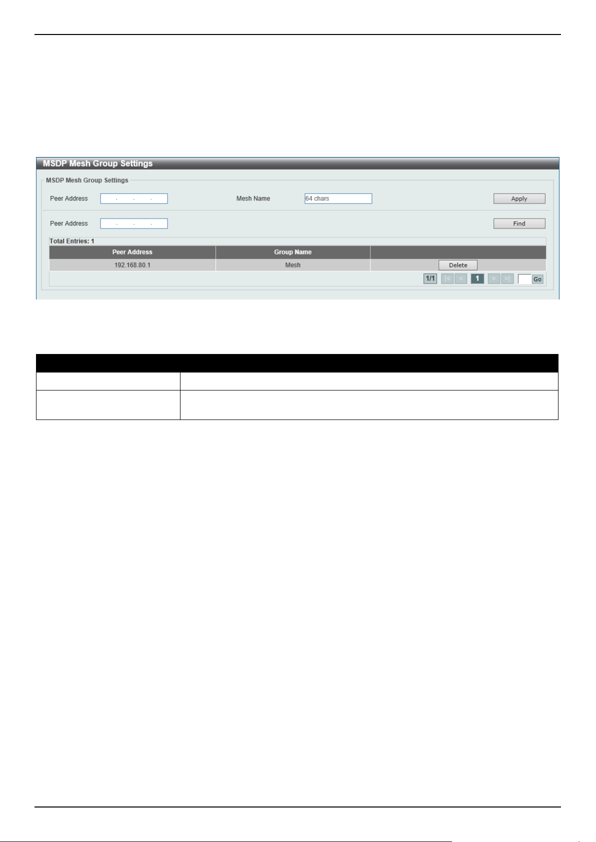
DGS-1520 Series Gigabit Ethernet Smart Managed Switch Web UI Reference Guide
324
MSDP Mesh Group Settings
This window is used to display and configure the MSDP mesh group settings. Before adding an MSDP peer to the
mesh group, an MSDP peer must be added first. If an MSDP peer has been added to multiple mesh groups, only the
last configuration takes effect.
To view the following window, click L3 Features > IP Multicast Routing Protocol > PIM > MSDP > MSDP Mesh
Group Settings, as shown below:
Figure 6-128 MSDP Mesh Group Settings Window
The fields that can be configured are described below:
Parameter Description
Peer Address
Enter the MSDP peer IP address here.
Mesh Name
Enter the name of the mesh group here. This string can be up to 64 characters
long.
Click the Apply button to accept the changes made.
Click the Find button to find and display an entry based on the information entered.
Click the Delete button to delete the specified entry.
Enter a page number and click the Go button to navigate to a specific page when multiple pages exist.
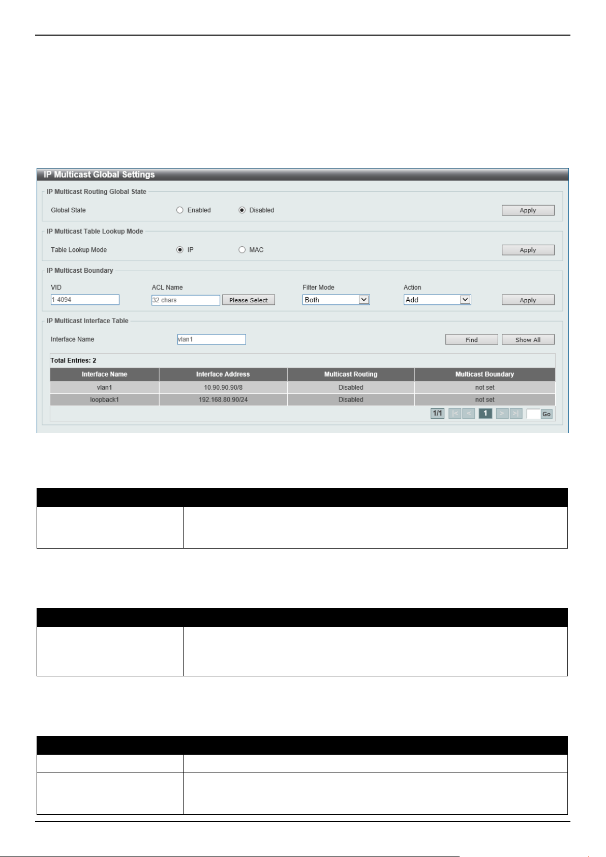
DGS-1520 Series Gigabit Ethernet Smart Managed Switch Web UI Reference Guide
325
IPMC
IP Multicast Global Settings
This window is used to display and configure the global IP Multicast (IPMC) settings.
To view the following window, click L3 Features > IP Multicast Routing Protocol > IPMC > IP Multicast Global
Settings, as shown below:
Figure 6-129 IP Multicast Global Settings Window
The fields that can be configured in IP Multicast Routing Global State are described below:
Parameter Description
Global State
Select to globally enable or disable the IP multicast routing feature here. When IP
multicast routing is disabled, the system will stop routing multicast packets even
though the multicast routing protocol is enabled.
Click the Apply button to accept the changes made.
The fields that can be configured in IP Multicast Table Lookup Mode are described below:
Parameter Description
Table Lookup Mode
Select the IP multicast forwarding lookup mode here. Options to choose from are:
• IP - Specifies multicast forwarding lookup based on the IP address.
• MAC - Specifies multicast forwarding lookup based on the MAC address.
Click the Apply button to accept the changes made.
The fields that can be configured in IP Multicast Boundary are described below:
Parameter Description
VID
Enter the VLAN ID that will be used here. The range is from 1 to 4094.
ACL Name
Enter the name of the standard IP access list that will be used here. This name
can be up to 32 characters long. Click the Please Select button to select a pre-
configured access list and use it here.
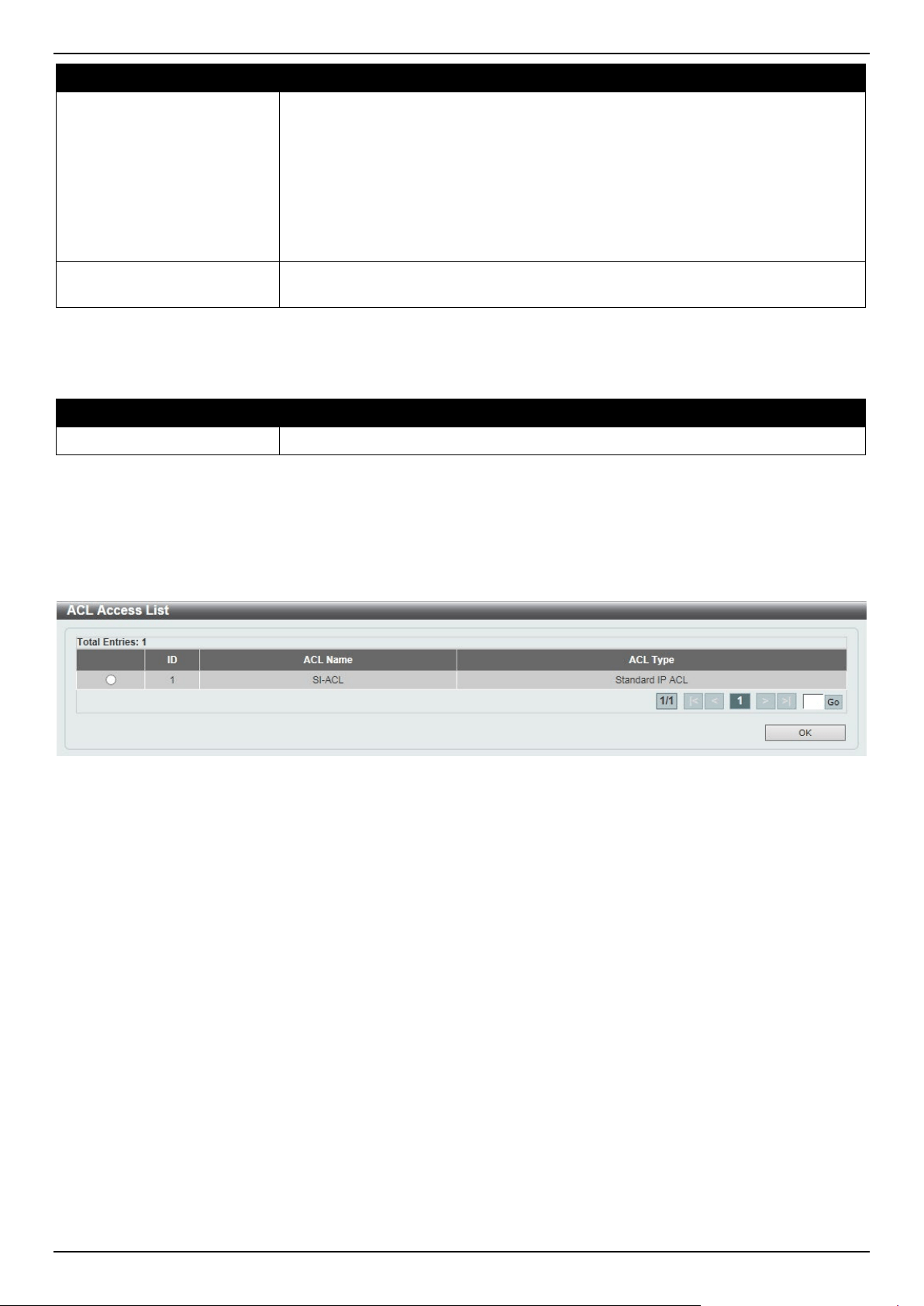
DGS-1520 Series Gigabit Ethernet Smart Managed Switch Web UI Reference Guide
326
Parameter Description
Filter Mode
Select the filter mode here. Options to choose from are:
• Both - Specifies to filter both incoming and outgoing traffic.
• Out - Specifies to filter the PIM join message or IGMP join message arriving
at the interface. This filtering prevent the interface from becoming an
outgoing interface for the denied (*,G) or (S,G) entries.
• In - Specifies to filter the multicast user traffic arriving at the interface based
on the specified access list. This filters the multicast traffic for the specific
group traffic or for specific groups from the specific source.
Action Select the action that will be taken here. Options to choose from are Add and
Delete.
Click the Apply button to accept the changes made.
The fields that can be configured in IP Multicast Interface Table are described below:
Parameter Description
Interface Name
Enter the interface name that will be used for the search here.
Click the Find button to locate a specific entry based on the information entered.
Click the Show All button to display all the entries.
Enter a page number and click the Go button to navigate to a specific page when multiple pages exist.
After clicking the Please Select button, the following page will appear.
Figure 6-130 IP Multicast Global Settings (Please Select) Window
Select the ACL and click the OK button to use the selected access list.
Enter a page number and click the Go button to navigate to a specific page when multiple pages exist.
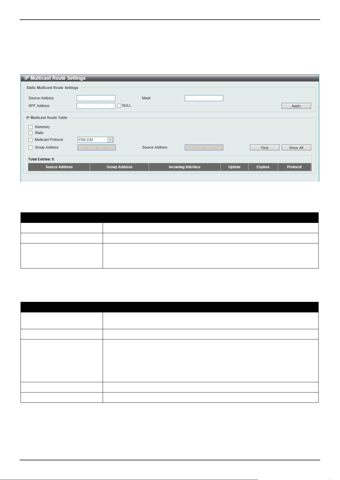
DGS-1520 Series Gigabit Ethernet Smart Managed Switch Web UI Reference Guide
327
IP Multicast Route Settings
This window is used to display and configure the IP multicast route settings.
To view the following window, click L3 Features > IP Multicast Routing Protocol > IPMC > IP Multicast Route
Settings, as shown below:
Figure 6-131 IP Multicast Route Settings Window
The fields that can be configured in Static Multicast Route Settings are described below:
Parameter Description
Source Address
Enter the network address of the multicast source here.
Mask
Specifies the network mask for the multicast source here.
RPF Address
Enter the RPF neighbor IP address to reach the network here.
Selecting the NULL option specifies that the RPF check will always fail for
multicast traffic sent from this source network.
Click the Apply button to accept the changes made.
The fields that can be configured in IP Multicast Route Table are described below:
Parameter Description
Summary
Selecting this option specifies to display a one-line, abbreviated summary of each
entry in the IP multicast routing table.
Static
Selecting this option specifies to display the multicast static routes.
Multicast Protocol
Select this option and then select the multicast protocol that will be used in this
display here. Options to choose from are:
• PIM-DM - Specifies to display only the PIM-DM routes.
• PIM-SM - Specifies to display only the PIM-SM routes.
• DVMRP - Specifies to display only the DVMRP routes.
Group Address
Select and enter the multicast group IP address here.
Source Address
Enter the source IP address here.
Click the Find button to locate a specific entry based on the information entered.
Click the Show All button to display all the entries.
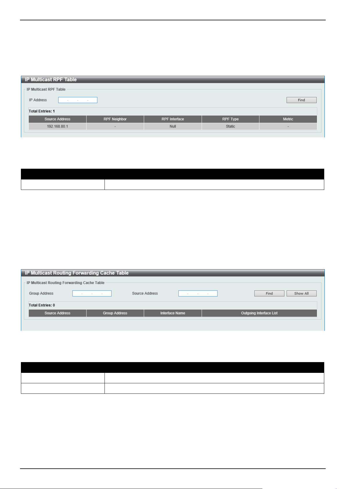
DGS-1520 Series Gigabit Ethernet Smart Managed Switch Web UI Reference Guide
328
IP Multicast RPF Table
This window is used to display Reverse Path Forwarding (RPF) information for a given unicast host address.
To view the following window, click L3 Features > IP Multicast Routing Protocol > IPMC > IP Multicast RPF Table,
as shown below:
Figure 6-132 IP Multicast RPF Table Window
The fields that can be configured are described below:
Parameter Description
IP Address
Enter the unicast host IPv4 address here.
Click the Find button to locate a specific entry based on the information entered.
IP Multicast Routing Forwarding Cache Table
This window is used to display the content of the IP multicast routing forwarding cache database.
To view the following window, click L3 Features > IP Multicast Routing Protocol > IPMC > IP Multicast Routing
Forwarding Cache Table, as shown below:
Figure 6-133 IP Multicast Routing Forwarding Cache Table Window
The fields that can be configured are described below:
Parameter Description
Group Address
Enter the multicast group IP address here.
Source Address
Enter the source IP address here.
Click the Find button to locate a specific entry based on the information entered.
Click the Show All button to display all the entries.
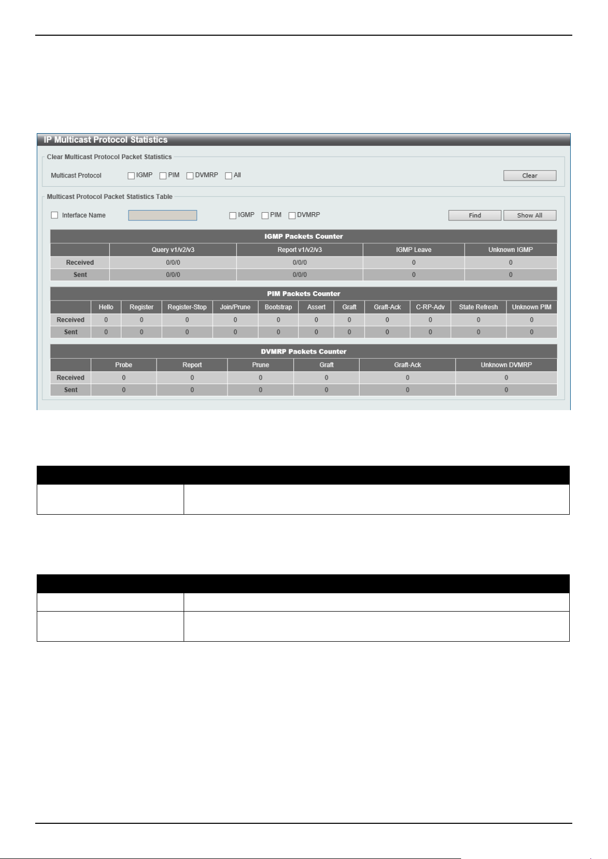
DGS-1520 Series Gigabit Ethernet Smart Managed Switch Web UI Reference Guide
329
IP Multicast Protocol Statistics
This window is used to view and clear the IP multicast protocol statistics information.
To view the following window, click L3 Features > IP Multicast Routing Protocol > IPMC > IP Multicast Protocol
Statistics, as shown below:
Figure 6-134 IP Multicast Protocol Statistics Window
The fields that can be configured in Clear Multicast Protocol Packet Statistics are described below:
Parameter Description
Multicast Protocol
Select the multicast protocol that will be cleared here. Options to choose from are
IGMP, PIM, DVMRP, and All.
Click the Clear button to clear the entries based on the information specified.
The fields that can be configured in Multicast Protocol Packet Statistics Table are described below:
Parameter Description
Interface Name
Select and enter the interface name that will be used in the display here.
Multicast Protocol
Select the multicast protocol that will be used in the display here. Options to
choose from are IGMP, PIM, and DVMRP.
Click the Find button to locate a specific entry based on the information entered.
Click the Show All button to display all the entries.
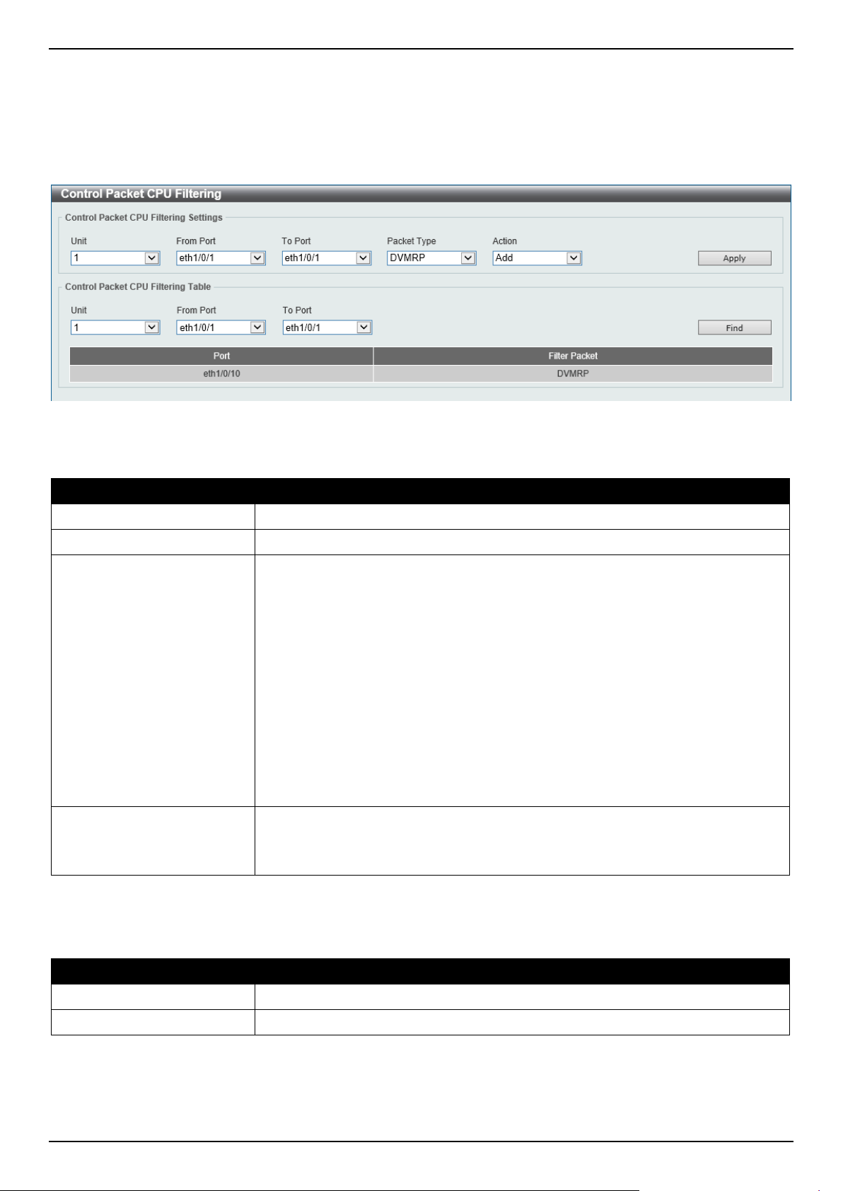
DGS-1520 Series Gigabit Ethernet Smart Managed Switch Web UI Reference Guide
330
Control Packet CPU Filtering
This window is used to display and configure the IPMC control packet CPU filtering settings.
To view the following window, click L3 Features > IP Multicast Routing Protocol > IPMC > Control Packet CPU
Filtering, as shown below:
Figure 6-135 Control Packet CPU Filtering Window
The fields that can be configured in Control Packet CPU Filtering Settings are described below:
Parameter Description
Unit
Select the Switch unit that will be used for this configuration here.
From Port - To Port
Select the range of ports that will be used for this configuration here.
Packet Type
Select the packet type here. Options to choose from are:
• DVMRP - Specifies that the CPU will discard DVMRP Layer 3 control
packets sent to it.
• PIM - Specifies that the CPU will discard PIM Layer 3 control packets sent
to it.
• IGMP Query - Specifies that the CPU will discard IGMP Query Layer 3
control packets sent to it.
• OSPF - Specifies that the CPU will discard OSPF Layer 3 control packets
sent to it.
• RIP - Specifies that the CPU will discard RIP Layer 3 control packets sent to
it.
• VRRP - Specifies that the CPU will discard VRRP Layer 3 control packets
sent to it.
Action
Select the action that will be taken here. Options to choose from are:
• Add - Specifies to add a new entry based on the information entered.
• Delete - Specifies to delete an entry based on the information entered.
Click the Apply button to accept the changes made.
The fields that can be configured in Control Packet CPU Filtering Table are described below:
Parameter Description
Unit
Select the Switch unit that will be used for this display here.
From Port - To Port
Select the range of ports that will be used for this display here.
Click the Find button to find and display entries based on the selections made.
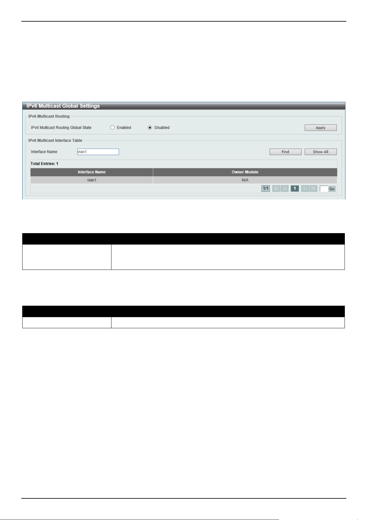
DGS-1520 Series Gigabit Ethernet Smart Managed Switch Web UI Reference Guide
331
IPv6MC
IPv6 Multicast Global Settings
This window is used to display and configure the global IPv6 multicast settings.
To view the following window, click L3 Features > IP Multicast Routing Protocol > IPv6MC > IPv6 Multicast Global
Settings, as shown below:
Figure 6-136 IPv6 Multicast Global Settings Window
The fields that can be configured in IPv6 Multicast Routing are described below:
Parameter Description
IPv6 Multicast Routing
Global State
Select to globally enable or disable the IPv6 multicast routing feature here. When
IPv6 multicast routing is disabled, the system will stop routing multicast packets
even though the multicast routing protocol is enabled.
Click the Apply button to accept the changes made.
The fields that can be configured in IPv6 Multicast Interface Table are described below:
Parameter Description
Interface Name
Enter the VLAN interface name that will be used here.
Click the Find button to locate a specific entry based on the information entered.
Click the Show All button to display all the entries.
Enter a page number and click the Go button to navigate to a specific page when multiple pages exist.
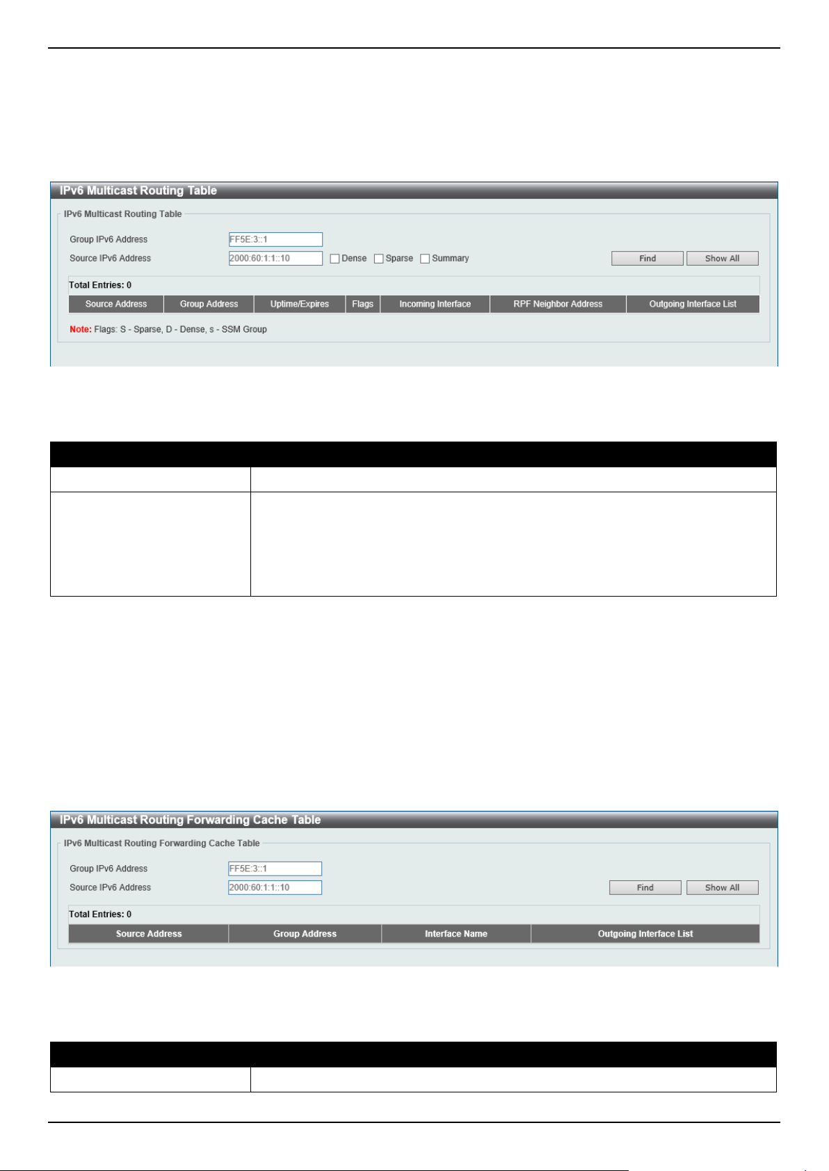
DGS-1520 Series Gigabit Ethernet Smart Managed Switch Web UI Reference Guide
332
IPv6 Multicast Routing Table
This window is used to display the contents of the IPv6 dynamic multicast routing table.
To view the following window, click L3 Features > IP Multicast Routing Protocol > IPv6MC > IPv6 Multicast
Routing Table, as shown below:
Figure 6-137 IPv6 Multicast Routing Table Window
The fields that can be configured are described below:
Parameter Description
Group IPv6 Address
Enter the multicast group IPv6 address here.
Source IPv6 Address
Enter the source IPv6 address here. Additional options to choose from are:
• Dense - Specifies to display PIM-DM routes only.
• Sparse - Specifies to display PIM-SM routes only.
• Summary - Specifies to display a one-line, abbreviated summary of each
entry in the IPv6 multicast routing table.
Click the Find button to locate a specific entry based on the information entered.
Click the Show All button to display all the entries.
IPv6 Multicast Routing Forwarding Cache Table
This window is used to display the contents of the IPv6 multicast routing forwarding cache database.
To view the following window, click L3 Features > IP Multicast Routing Protocol > IPv6MC > IPv6 Multicast
Routing Forwarding Cache Table, as shown below:
Figure 6-138 IPv6 Multicast Routing Forwarding Cache Table Window
The fields that can be configured are described below:
Parameter Description
Group IPv6 Address
Enter the multicast group IPv6 address here.
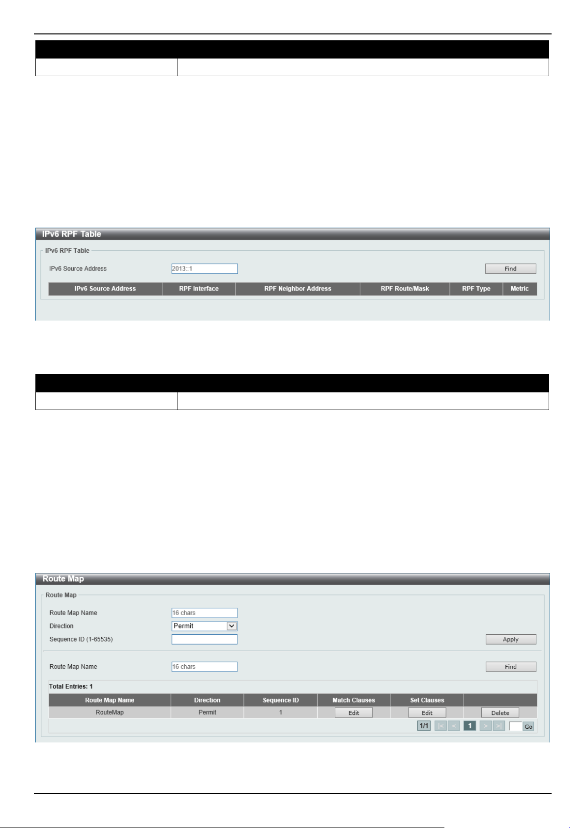
DGS-1520 Series Gigabit Ethernet Smart Managed Switch Web UI Reference Guide
333
Parameter Description
Source IPv6 Address
Enter the source IPv6 address here.
Click the Find button to locate a specific entry based on the information entered.
Click the Show All button to display all the entries.
IPv6 RPF Table
This window is used to display Reverse Path Forwarding (RPF) information for a given unicast host address.
To view the following window, click L3 Features > IP Multicast Routing Protocol > IPv6MC > IPv6 RPF Table, as
shown below:
Figure 6-139 IPv6 RPF Table Window
The fields that can be configured are described below:
Parameter Description
IPv6 Source Address
Enter the unicast host IPv6 address here.
Click the Find button to locate a specific entry based on the information entered.
IP Route Filter
Route Map
This window is used to display and configure the route map settings.
To view the following window, click L3 Features > IP Route Filter > Route Map, as shown below:
Figure 6-140 Route Map Window
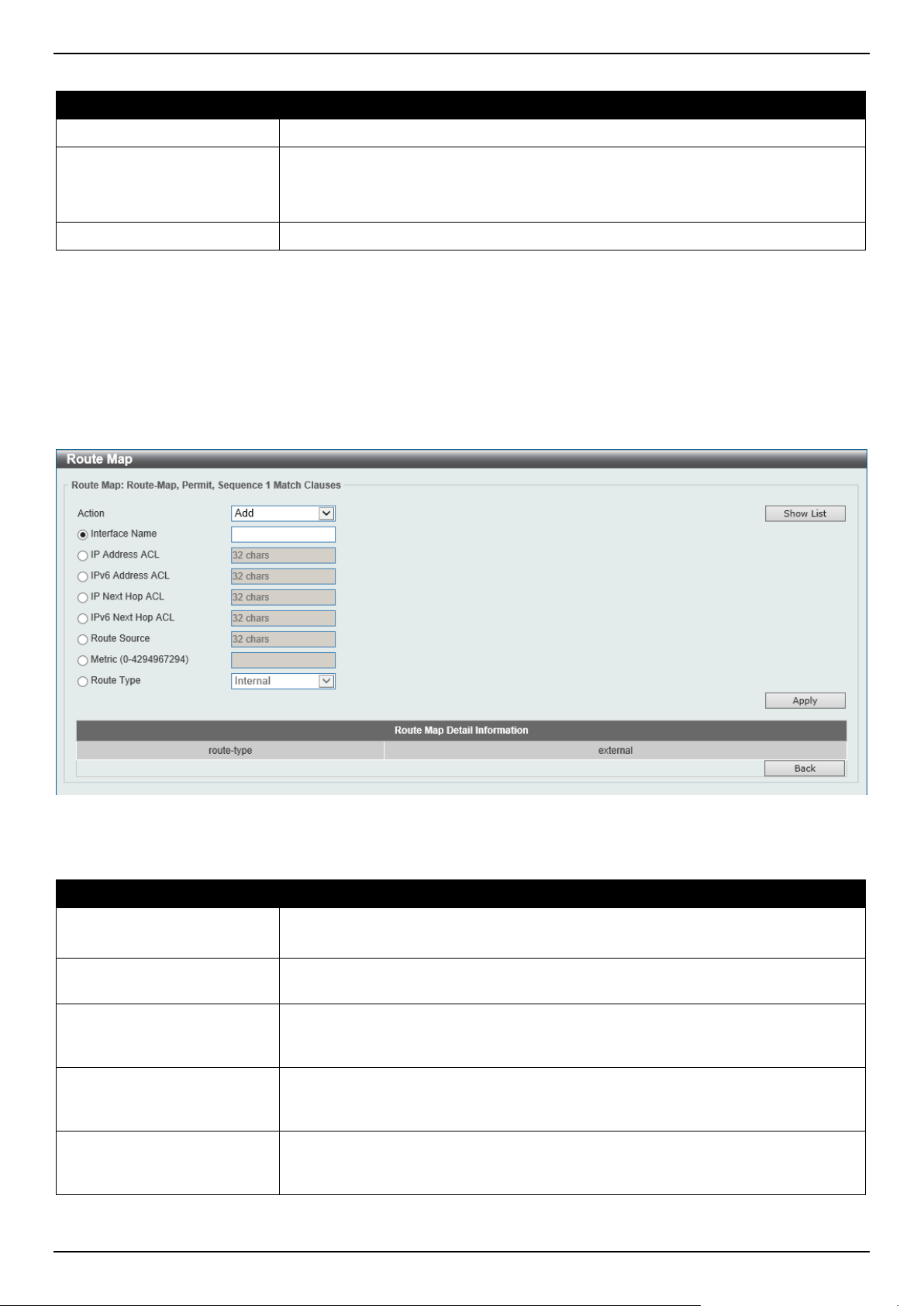
DGS-1520 Series Gigabit Ethernet Smart Managed Switch Web UI Reference Guide
334
The fields that can be configured are described below:
Parameter Description
Route Map Name
Enter the route map name here. This name can be up to 16 characters long.
Direction
Select the direction for this rule here. Options to choose from are:
• Permit - Specifies that routes that match the rule entry are permitted.
• Deny - Specifies that routes that match the rule entry are denied.
Sequence ID
Enter the sequence ID for this rule here. The range is from 1 to 65535.
Click the Apply button to accept the changes made.
Click the Find button to locate a specific entry based on the information entered.
Click the Edit button to modify the specified entry.
Click the Delete button to delete the specified entry.
Enter a page number and click the Go button to navigate to a specific page when multiple pages exist.
After clicking the Edit button in the Match Clauses column, the following page will appear.
Figure 6-141 Route Map (Match Clauses, Edit) Window
The fields that can be configured are described below:
Parameter Description
Action Select Add to add a new entry based in the information entered.
Select Delete to delete an entry based in the information entered.
Interface Name
Select and enter the interface name that will be used here. This option is used to
define a clause to match the route's outgoing interface.
IP Address ACL
Select and enter the standard or extended IP access list name here. This option is
used to define a clause to match the route based on the standard or extended IP
access list. This string can be up to 32 characters long.
IPv6 Address ACL
Select and enter the standard or extended IPv6 access list name here. This option
is used to define a clause to match the route based on the standard or extended
IPv6 access list. This string can be up to 32 characters long.
IP Next Hop ACL
Select and enter the standard IP access list name here. This option is used to
define a clause to match the route's next hop based on the standard IP access list.
This string can be up to 32 characters long.
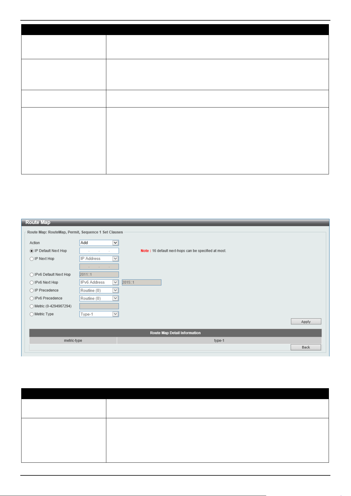
DGS-1520 Series Gigabit Ethernet Smart Managed Switch Web UI Reference Guide
335
Parameter Description
IPv6 Next Hop ACL
Select and enter the standard IPv6 access list name here. This option is used to
define a clause to match the route's next hop based on the standard IPv6 access
list. This string can be up to 32 characters long.
Route Source
Select and enter the standard or extended IP/IPv6 access list name here. This
option is used to define a clause to match the route's source based on the
standard or extended IP/IPv6 access list. This string can be up to 32 characters
long.
Metric
Select and enter the metric value of the route here. The range is from 0 to
4294967294. This option is used to define a clause to match the route metric.
Route Type
Select the route type here. Options to choose from are:
• Internal - Specifies the intra-area and inter-area routes of Open Shortest
Path First (OSPF).
• External - Specifies the autonomous system's external route of OSPF. If the
type-1 and type-2 options are not specified, type-1 and type-2 external
routes are included.
• External Type-1 - Specifies the type-1 external route of OSPF.
• External Type-2 - Specifies the type-2 external route of OSPF.
Click the Apply button to accept the changes made.
Click the Back button to return to the previous window.
After clicking the Edit button in the Set Clauses column, the following page will appear.
Figure 6-142 Route Map (Set Clauses, Edit) Window
The fields that can be configured are described below:
Parameter Description
Action Select Add to add a new entry based in the information entered.
Select Delete to delete an entry based in the information entered.
IP Default Next Hop
Enter the default next-hop IP address in the space provided that will be used to
route the packet. This feature can be used to specify multiple default next hop
routers. If default next hops are already configured, the default next hops
configured later will be added to the default next hop list. When the first default
next hop router specified is down, the next default next hop router specified is tried
in turn to route the packet. Up to 16 default next-hop IP addresses can be entered.

DGS-1520 Series Gigabit Ethernet Smart Managed Switch Web UI Reference Guide
336
Parameter Description
IP Next Hop
Select the IP next hop type here. This feature is used to configure the next-hop
router to route the packet that passes the match clauses of the configured route
map sequence. Options to choose from are:
• IP Address - Specifies the IP addresses of the next-hops to route the
packet. Enter the next-hop IP addresses in the spaces provided here. Up to
16 next-hop IP addresses can be entered.
• Recursive - Specifies the IP address of the recursive as the next-hop
router. Enter the recursive next-hop IP address in the space provided here.
IPv6 Default Next Hop
Enter the default next-hop IPv6 address in the space provided that will be used to
route the packet. This feature can be used to specify multiple default next hop
routers. If default next hops are already configured, the default next hops
configured later will be added to the default next hop list. When the first default
next hop router specified is down, the next default next hop router specified is tried
in turn to route the packet. Up to 16 default next-hop IPv6 addresses can be
entered.
IPv6 Next Hop
Select the IPv6 next hop type here. This feature is used to configure the next-hop
router to route the packet that passes the match clauses of the configured route
map sequence. Options to choose from are:
• IPv6 Address - Specifies the IPv6 addresses of the next-hops to route the
packet. Enter the next-hop IPv6 addresses in the space provided here.
• Recursive - Specifies the IPv6 address of the recursive as the next-hop
router. Enter the recursive next-hop IPv6 address in the space provided
here.
IP Precedence Select the IP precedence option here. Options to choose from are Routine,
Priority, Immediate, Flash, Flash Override, Critical, Internet, and Network. Use
this feature to set the precedence value in the IP header. This option only takes
effect when policy routing involves the IPv4 packet.
IPv6 Precedence Select the IPv6 precedence option here. Options to choose from are Routine,
Priority, Immediate, Flash, Flash Override, Critical, Internet, and Network. Use
this feature to set the precedence value in the IPv6 header. This option only takes
effect when policy routing involves the IPv6 packet.
Metric
Select and enter the metric value here that will be used in the modification. The
range is from 0 to 4294967294.
Metric Type
Select the metric type here that will be used in the modification. Options to choose
from are:
• Type-1 - Specifies to use the OSPF external type-1 metric.
• Type-2 - Specifies to use the OSPF external type-2 metric.
Click the Apply button to accept the changes made.
Click the Back button to return to the previous window.
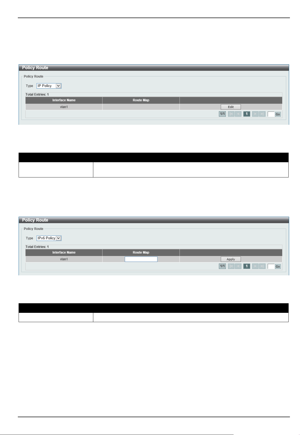
DGS-1520 Series Gigabit Ethernet Smart Managed Switch Web UI Reference Guide
337
Policy Route
This window is used to display and configure the policy route settings.
To view the following window, click L3 Features > Policy Route, as shown below:
Figure 6-143 Policy Route Window
The fields that can be configured are described below:
Parameter Description
Type Select the policy route type here. Options to choose from are IP Policy and IPv6
Policy.
Click the Edit button to modify the specified entry.
Enter a page number and click the Go button to navigate to a specific page when multiple pages exist.
After clicking the Edit button, the following page will appear.
Figure 6-144 Policy Route (Edit) Window
The fields that can be configured are described below:
Parameter Description
Route Map
Enter the route map name here that will be used in this policy route entry.
Click the Apply button to accept the changes made.
VRRP Settings
This window is used to display and configure the Virtual Router Redundancy Protocol (VRRP) settings. All routers in
the same VRRP group must be configured with the same virtual router ID and IP address.
A virtual router group is represented by a virtual router ID. The IP address of the virtual router is the default router
configured on hosts. The virtual router's IP address can be a real address configured on the routers, or an unused IP
address. If the virtual router address is a real IP address, the router that has this IP address is the IP address owner.
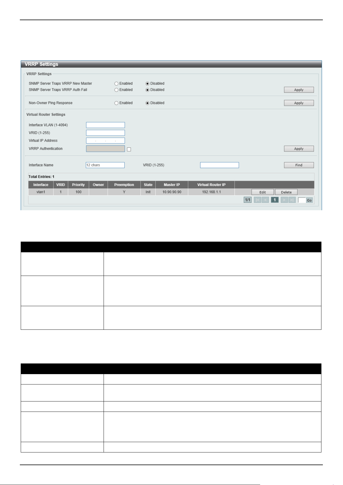
DGS-1520 Series Gigabit Ethernet Smart Managed Switch Web UI Reference Guide
338
A master will be elected in a group of routers that supports the same virtual routers. Others are the backup routers.
The master is responsible for forwarding the packets that are sent to the virtual router.
To view the following window, click L3 Features > VRRP Settings, as shown below:
Figure 6-145 VRRP Settings Window
The fields that can be configured in VRRP Settings are described below:
Parameter Description
SNMP Server Traps VRRP
New Master
Select to enable or disable the SNMP server traps feature for the new VRRP
master. If enabled, once the device has transitioned to the master state, a trap will
be sent out.
SNMP Server Traps VRRP
Auth Fail
Select to enable or disable the SNMP server traps feature for authentication
failures. If enabled, if a packet has been received from a router whose
authentication key or authentication type conflicts with this router's authentication
key or authentication type, then a trap will be sent out.
Non-Owner Ping Response
Select to enable or disable the non-owner ping response feature here. This feature
is used to enable the virtual router in the master state to respond to ICMP echo
requests for an IP address not owned but associated with this virtual router.
Click the Apply button to accept the changes made.
The fields that can be configured in Virtual Router Settings are described below:
Parameter Description
Interface VLAN
Enter the VLAN interface ID used here. The range is from 1 to 4094.
VRID
Enter the ID of the virtual router that will be created here. This ID is used to identify
the virtual router in the VRRP group. The range is from 1 to 255.
Virtual IP Address
Enter the IPv4 address for the created virtual router group here.
VRRP Authentication
Select to enable and then enter the plain text authentication password for VRRP
authentication on the interface here. This string can be up to 8 characters long.
The authentication is applied to all virtual routers on this interface. The devices in
the same VRRP group must have the same authentication password.
Interface Name
Enter the interface name used here. This name can be up to 12 characters long.
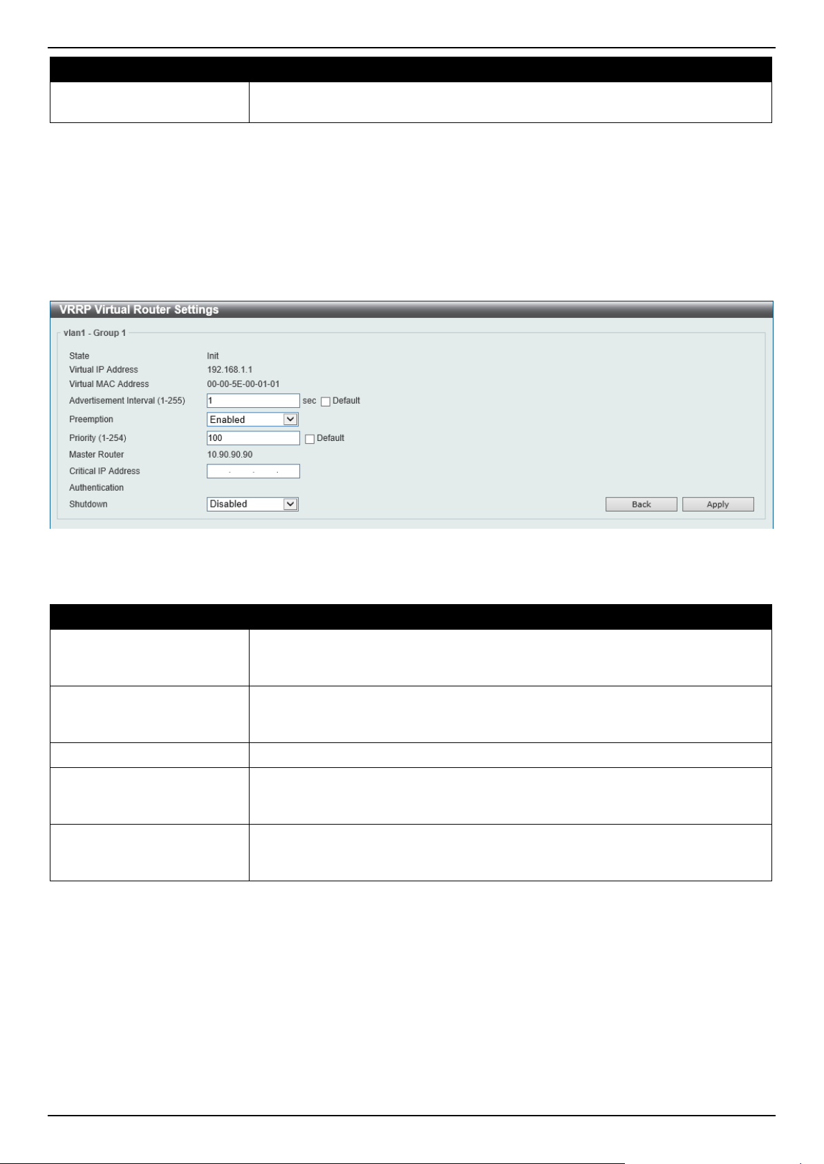
DGS-1520 Series Gigabit Ethernet Smart Managed Switch Web UI Reference Guide
339
Parameter Description
VRID
Enter the ID of the virtual router that will be displayed here. The range is from 1 to
255.
Click the Apply button to accept the changes made.
Click the Find button to locate a specific entry based on the information entered.
Click the Edit button to modify the specified entry.
Click the Delete button to delete the specified entry.
Enter a page number and click the Go button to navigate to a specific page when multiple pages exist.
After clicking the Edit button, the following page will appear.
Figure 6-146 VRRP Settings (Edit) Window
The fields that can be configured are described below:
Parameter Description
Advertisement Interval
Enter the advertisement interval value here. This is the time interval between
successive VRRP advertisements by the master router. The range is from 1 to 255
seconds. By default, this value is 1 second.
Preemption
Select to enable or disable the preemption feature here. This feature is used to
allow a router to take over the master role if it has a better priority than the current
master.
Priority
Enter the priority value here. The range is from 1 to 254.
Critical IP Address
Enter the critical IPv4 address here. If the critical IP is configured on one virtual
router, the virtual router cannot be activated when the critical IP address is
unreachable. One VRRP group can only track one critical IP.
Shutdown
Select to enable or disable the shutdown feature here. This feature is used to
disable a virtual router on an interface. Avoid the common mistake of shutting
down the IP address owner router before shutting down other non-owner routers.
Click the Back button to return to the previous window.
Click the Apply button to accept the changes made.
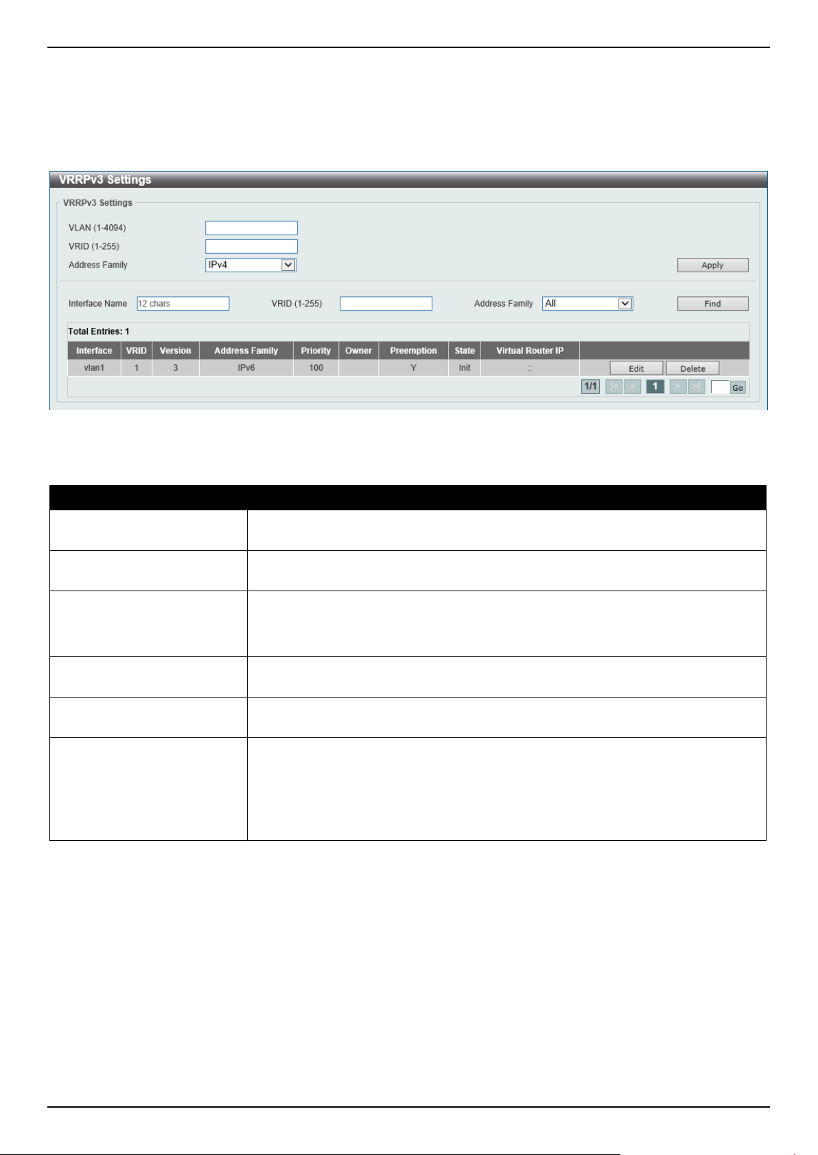
DGS-1520 Series Gigabit Ethernet Smart Managed Switch Web UI Reference Guide
340
VRRPv3 Settings
This window is used to display and configure the VRRP version 3 (VRRPv3) settings.
To view the following window, click L3 Features > VRRPv3 Settings, as shown below:
Figure 6-147 VRRPv3 Settings Window
The fields that can be configured are described below:
Parameter Description
VLAN
Enter the ID of the VLAN interface that will be used here. The range is from 1 to
4094.
VRID
Enter the ID of the virtual router that will be created here. The range is from 1 to
255.
Address Family
Select the address family used here. Options to choose from are:
• IPv4 - Specifies to create an IPv4 virtual router.
• IPv6 - Specifies to create an IPv6 virtual router.
Interface Name
Enter the name of the VLAN interface that will be used in the display here. This
string can be up to 12 characters long.
VRID
Enter the ID of the virtual router that will be displayed here. The range is from 1 to
255.
Address Family
Select the address family that will be used in the display here. Options to choose
from are:
• All - Specifies to display all virtual routers.
• IPv4 - Specifies to display IPv4 virtual routers only.
• IPv6 - Specifies to display IPv6 virtual routers only.
Click the Apply button to accept the changes made.
Click the Find button to find and display an entry based on the information entered.
Click the Edit button to configure detailed settings of the specified entry.
Click the Delete button to delete the specified entry.
Enter a page number and click the Go button to navigate to a specific page when multiple pages exist.
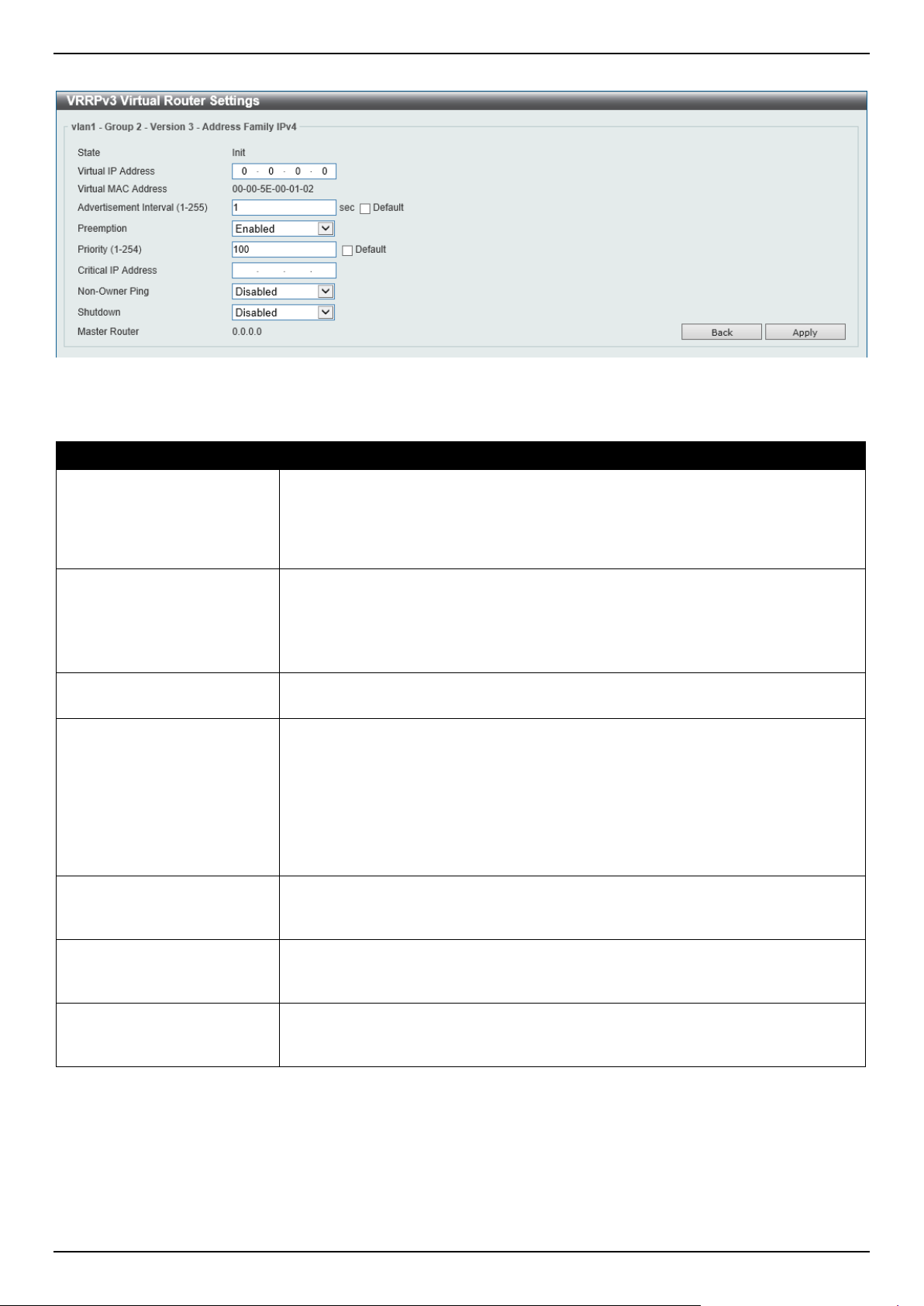
DGS-1520 Series Gigabit Ethernet Smart Managed Switch Web UI Reference Guide
341
After clicking the Edit button next to the IPv4 Address Family entry, the following window will appear:
Figure 6-148 VRRPv3 Settings (Edit, IPv4) Window
The fields that can be configured are described below:
Parameter Description
Virtual IP Address
Enter the virtual IPv4 address here. All routers in the same VRRP group must be
configured with the same virtual router ID and virtual address. The IPv4 address of
the virtual router can be a real address configured on the routers or an unused
address. If the virtual address is equal to the real address of the interface, this
virtual router is the IPv4 address owner.
Advertisement Interval
Enter the time interval value between successive advertisements by the master
router here. The range is from 1 to 255 seconds. The master will constantly send
VRRP advertisements. All virtual routers in a VRRP group must use the same
timer values.
Select the Default option to use the default value.
Preemption
Select to enable or disable the preemption feature here. This is used to allow a
router to take over the master role if it has a better priority than the current master.
Priority
Enter the priority value of the virtual router here. The range is from 1 to 254. The
master of a VRRP group is elected based on the priority. The virtual router with the
highest priority becomes the master and others with lower priorities act as the
backup for the VRRP group. If there are multiple routers with the same highest
priority value, the router with the larger IPv4 address will become the Master. The
router that is the IPv4 address owner of the VRRP group is always the master of
the VRRP group, and has the highest priority of 255.
Select the Default option to use the default value.
Critical IP Address
Enter the critical IPv4 address here. If the critical IPv4 is configured on one virtual
router, the virtual router cannot be activated when the critical IPv4 address is
unreachable. One VRRP group can only track one critical IPv4 address.
Non-Owner Ping
Select to enable or disable the non-owner ping feature here. This is used to enable
a non-IPv4 address owner virtual router in the master state to respond to ICMP
echo requests for IPv4 addresses.
Shutdown
Select to enable or disable the shutdown feature here. Avoid the common mistake
of shutting down the IPv4 address owner routers before shutting down other non-
owner routers.
Click the Back button to return to the previous window.
Click the Apply button to accept the changes made.
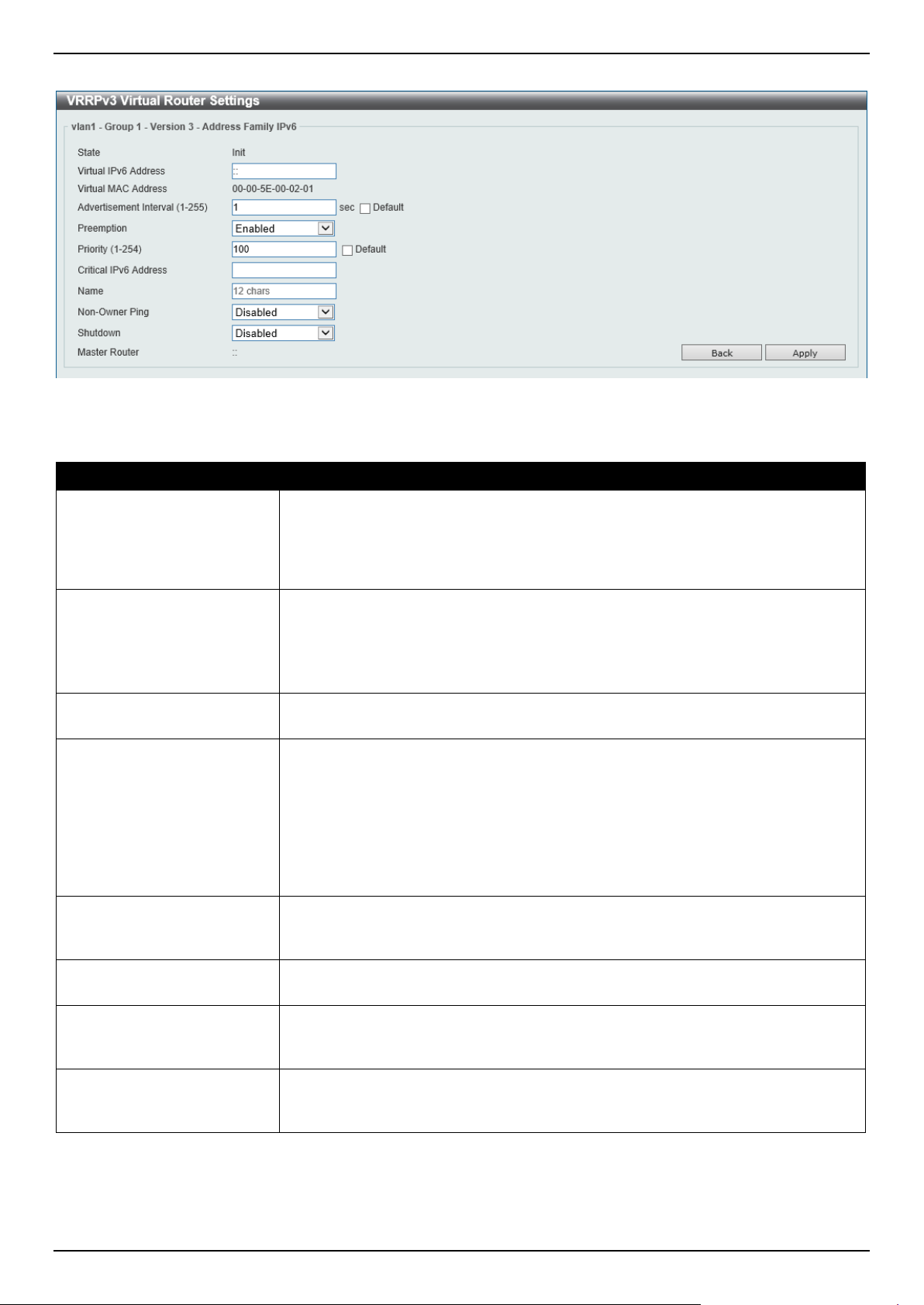
DGS-1520 Series Gigabit Ethernet Smart Managed Switch Web UI Reference Guide
342
After clicking the Edit button next to the IPv6 Address Family entry, the following window will appear:
Figure 6-149 VRRPv3 Settings (Edit, IPv6) Window
The fields that can be configured are described below:
Parameter Description
Virtual IPv6 Address
Enter the virtual IPv6 address here. All routers in the same VRRP group must be
configured with the same virtual router ID and virtual address. The IPv6 address of
the virtual router can be a real address configured on the routers or an unused
address. If the virtual address is equal to the real address of the interface, this
virtual router is the IPv6 address owner.
Advertisement Interval
Enter the time interval value between successive advertisements by the master
router here. The range is from 1 to 255 seconds. The master will constantly send
VRRP advertisements. All virtual routers in a VRRP group must use the same
timer values.
Select the Default option to use the default value.
Preemption
Select to enable or disable the preemption feature here. This is used to allow a
router to take over the master role if it has a better priority than the current master.
Priority
Enter the priority value of the virtual router here. The range is from 1 to 254. The
master of a VRRP group is elected based on the priority. The virtual router with the
highest priority becomes the master and others with lower priorities act as the
backup for the VRRP group. If there are multiple routers with the same highest
priority value, the router with the larger IP address will become the Master. The
router that is the IPv6 address owner of the VRRP group is always the master of
the VRRP group, and has the highest priority of 255.
Select the Default option to use the default value.
Critical IPv6 Address
Enter the critical IPv6 address here. If the critical IPv6 is configured on one virtual
router, the virtual router cannot be activated when the critical IPv6 address is
unreachable. One VRRP group can only track one critical IPv6 address.
Name
Enter the name for the IPv6 address family here. This can be up to 12 characters
long.
Non-Owner Ping
Select to enable or disable the non-owner ping feature here. This is used to enable
a non-IPv6 address owner virtual router in the master state to respond to ND
requests for IPv6 addresses.
Shutdown
Select to enable or disable the shutdown feature here. Avoid the common mistake
of shutting down the IPv6 address owner routers before shutting down other non-
owner routers.
Click the Back button to return to the previous window.
Click the Apply button to accept the changes made.
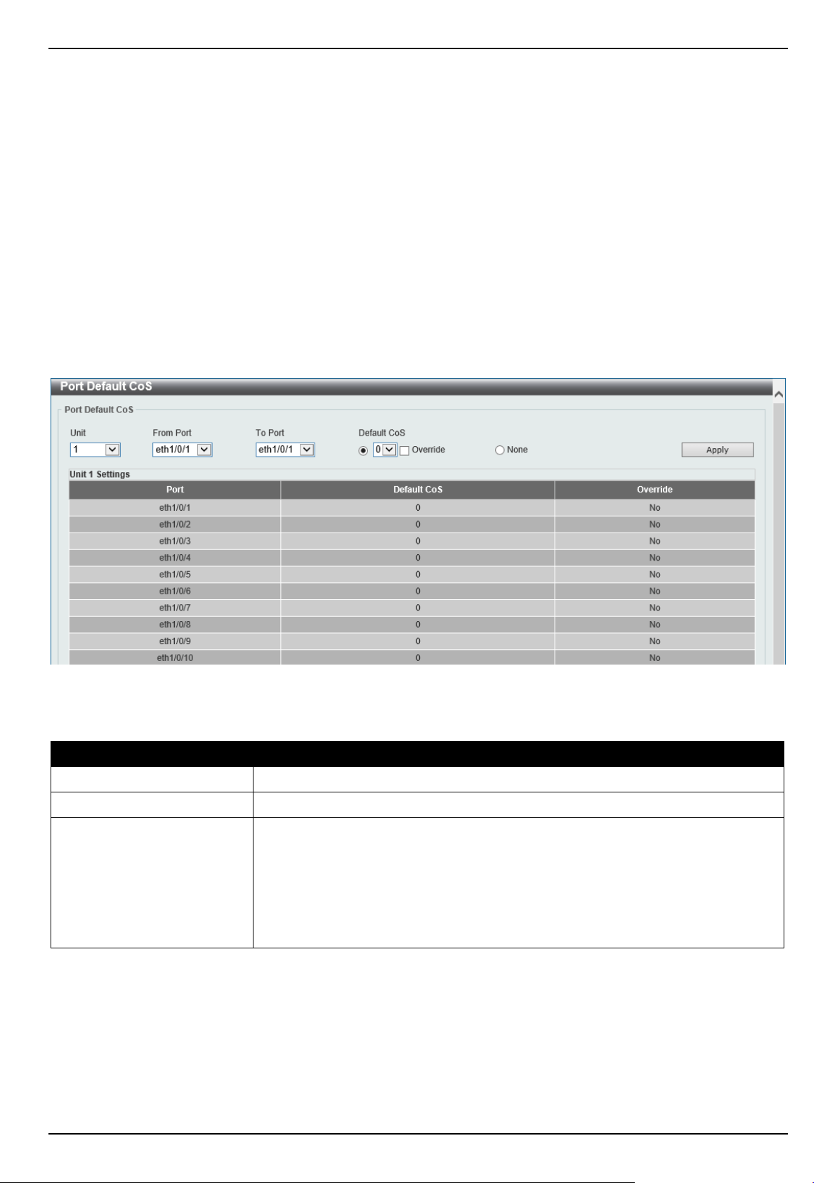
DGS-1520 Series Gigabit Ethernet Smart Managed Switch Web UI Reference Guide
343
7. Quality of Service (QoS)
Basic Settings
Advanced Settings
QoS PFC
WRED
Basic Settings
Port Default CoS
This window is used to display and configure the port default CoS settings.
To view the following window, click QoS > Basic Settings > Port Default CoS, as shown below:
Figure 7-1 Port Default CoS Window
The fields that can be configured are described below:
Parameter Description
Unit
Select the Switch unit that will be used for this configuration here.
From Port - To Port
Select the range of ports that will be used for this configuration here.
Default CoS
Select the default CoS option for the port(s) specified here. Options to choose from
are 0 to 7.
Select the Override option to override the CoS of the packets. The default CoS will
be applied to all incoming packets, tagged or untagged, received by the port.
Select the None option to specify that the CoS of the packets will be the packet's
CoS if the packets are tagged, and will be the port default CoS if the packet is
untagged.
Click the Apply button to accept the changes made.
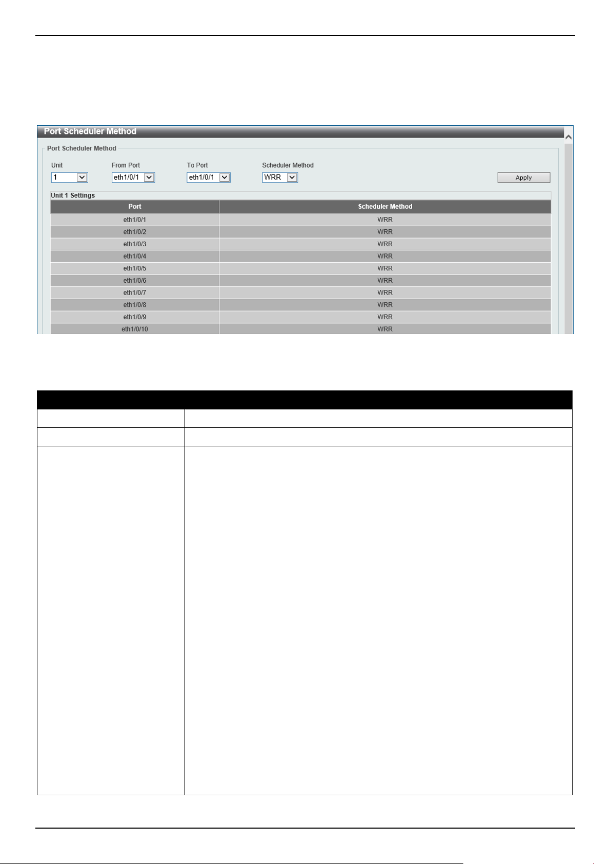
DGS-1520 Series Gigabit Ethernet Smart Managed Switch Web UI Reference Guide
344
Port Scheduler Method
This window is used to display and configure the port scheduler method settings.
To view the following window, click QoS > Basic Settings > Port Scheduler Method, as shown below:
Figure 7-2 Port Scheduler Method Window
The fields that can be configured are described below:
Parameter Description
Unit
Select the Switch unit that will be used for this configuration here.
From Port - To Port
Select the range of ports that will be used for this configuration here.
Scheduler Method
Select the scheduler method that will be applied to the specified port(s). Options to
choose from are:
• SP (Strict Priority) - Specifies that all queues use strict priority scheduling. It
provides strict priority access to the queues from the highest CoS queue to
the lowest.
• RR (Round-Robin) - Specifies that all queues use round-robin scheduling. It
provides fair access to service a single packet at each queue before moving
on to the next one.
• WRR (Weighted Round-Robin) - Operates by transmitting permitted packets
into the transmit queue in a round robin order. Initially, each queue sets its
weight to a configurable weighting. Every time a packet from a higher
priority CoS queue is sent, the corresponding weight is subtracted by 1 and
the packet in the next lower CoS queue will be serviced. When the weight of
a CoS queue reaches zero, the queue will not be serviced until its weight is
replenished. When weights of all CoS queues reach 0, the weights get
replenished at a time.
• WDRR (Weighted Deficit Round-Robin) - Operates by serving an
accumulated set of backlogged credits in the transmit queue in a round
robin order. Initially, each queue sets its credit counter to a configurable
quantum value. Every time a packet from a CoS queue is sent, the size of
the packet is subtracted from the corresponding credit counter and the
service right is turned over to the next lower CoS queue. When the credit
counter drops below 0, the queue is no longer serviced until its credits are
replenished. When the credit counters of all CoS queues reaches 0, the
credit counters will be replenished at that time. All packets are serviced until
their credit counter is zero or negative and the last packet is transmitted
completely. When this condition happens, the credits are replenished. When
the credits are replenished, a quantum of credits are added to each CoS
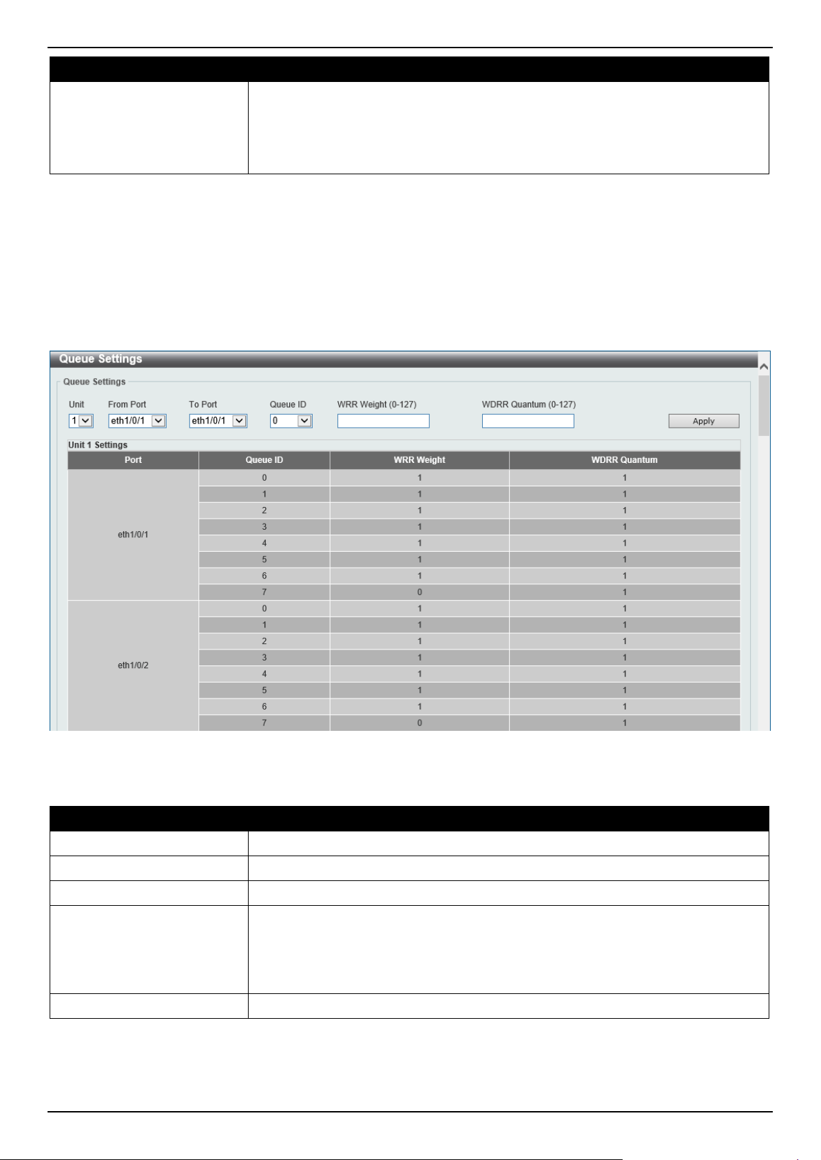
DGS-1520 Series Gigabit Ethernet Smart Managed Switch Web UI Reference Guide
345
Parameter Description
queue credit counter. The quantum for each CoS queue may be different
based on the user configuration.
To set a CoS queue in the SP mode, any higher priority CoS queue must
also be in the strict priority mode.
By default, the WRR option is used.
Click the Apply button to accept the changes made.
Queue Settings
This window is used to display and configure the queue settings.
To view the following window, click QoS > Basic Settings > Queue Settings, as shown below:
Figure 7-3 Queue Settings Window
The fields that can be configured are described below:
Parameter Description
Unit
Select the Switch unit that will be used for this configuration here.
From Port - To Port
Select the range of ports that will be used for this configuration here.
Queue ID
Enter the queue ID value here. This value must be between 0 and 7.
WRR Weight
Enter the WRR weight value here. This value must be between 0 and 127. To
satisfy the behavior requirements of Expedited Forwarding (EF), the highest queue
is always selected by the Per-hop Behavior (PHB) EF and the schedule mode of
this queue should be strict priority scheduling. Therefore, the weight of the last
queue should be zero while the Differentiate Service is supported.
WDRR Quantum
Enter the WDRR quantum value here. This value must be between 0 and 127.
Click the Apply button to accept the changes made.
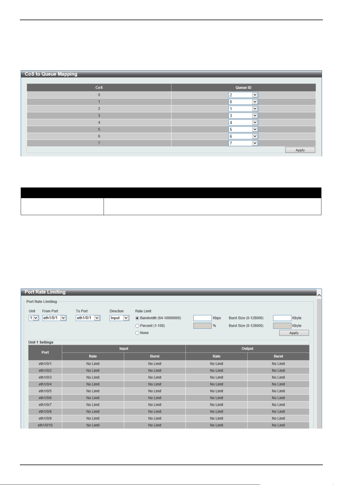
DGS-1520 Series Gigabit Ethernet Smart Managed Switch Web UI Reference Guide
346
CoS to Queue Mapping
This window is used to display and configure the CoS-to-Queue mapping settings.
To view the following window, click QoS > Basic Settings > CoS to Queue Mapping, as shown below:
Figure 7-4 CoS to Queue Mapping Window
The fields that can be configured are described below:
Parameter Description
Queue ID
Select the queue ID that will be mapped to the corresponding CoS value. Options
to choose from are 0 to 7.
Click the Apply button to accept the changes made.
Port Rate Limiting
This window is used to display and configure the port rate limiting settings.
To view the following window, click QoS > Basic Settings > Port Rate Limiting, as shown below:
Figure 7-5 Port Rate Limiting Window
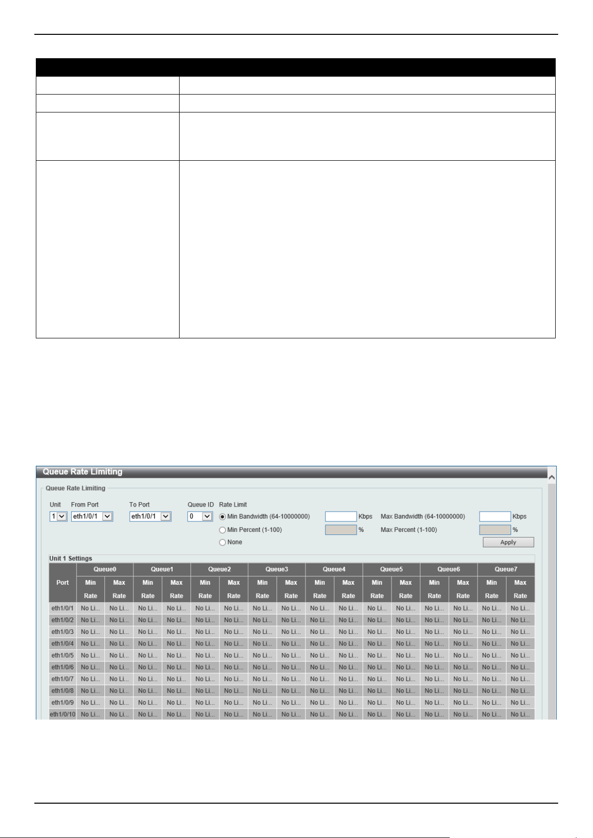
DGS-1520 Series Gigabit Ethernet Smart Managed Switch Web UI Reference Guide
347
The fields that can be configured are described below:
Parameter Description
Unit
Select the Switch unit that will be used for this configuration here.
From Port - To Port
Select the range of ports that will be used for this configuration here.
Direction
Select the direction option here. Options to choose from are:
• Input - The rate limit for ingress packets is configured.
• Output - The rate limit for egress packets is configured.
Rate Limit
Select and enter the rate limit value here.
• When Bandwidth is selected, enter the input/output bandwidth value used
in the space provided. This value must be between 64 and 10000000 kbps.
Also, enter the Burst Size value in the space provided. This value must be
between 0 and 128000 kilobytes.
• When Percent is selected, enter the input/output bandwidth percentage
value used in the space provided. This value must be between 1 and 100
percent (%). Also, enter the Burst Size value in the space provided. This
value must be between 0 and 128000 kilobytes.
• Select the None option to remove the rate limit on the specified port(s). The
specified limitation cannot exceed the maximum speed of the specified
interface. For the ingress bandwidth limitation, the ingress will send a pause
frame or a flow control frame when the received traffic exceeds the
limitation.
Click the Apply button to accept the changes made.
Queue Rate Limiting
This window is used to display and configure the queue rate limiting settings.
To view the following window, click QoS > Basic Settings > Queue Rate Limiting, as shown below:
Figure 7-6 Queue Rate Limiting Window

DGS-1520 Series Gigabit Ethernet Smart Managed Switch Web UI Reference Guide
348
The fields that can be configured are described below:
Parameter Description
Unit
Select the Switch unit that will be used for this configuration here.
From Port - To Port
Select the range of ports that will be used for this configuration here.
Queue ID
Select the queue ID that will be configured here. Options to choose from are 0 to 7.
Rate Limit
Select and enter the queue rate limit settings here.
• When the Min Bandwidth option is selected, enter the minimum bandwidth
rate limit value in the space provided. This value must be between 64 and
10000000 kbps. Also, enter the maximum bandwidth (Max Bandwidth) rate
limit in the space provided. This value must be between 64 and 10000000
kbps.
When the minimal bandwidth is configured, the packet transmitted from the
queue can be guaranteed. When the maximum bandwidth is configured,
packets transmitted from the queue cannot exceed the maximum bandwidth
even if the bandwidth is available.
When configuring the minimal bandwidth, the aggregate of the configured
minimum bandwidth must be less than 75 percent of the interface bandwidth
to make sure the configured minimal bandwidth can be guaranteed. It is not
necessary to set the minimum guaranteed bandwidth for the highest strict
priority queue. This is because the traffic in this queue will be serviced first if
the minimal bandwidth of all queues is satisfied.
The configuration of this command can only be attached to a physical port
but not a port-channel. That is the minimum guaranteed bandwidth of one
CoS cannot be used across physical ports.
• When the Min Percent option is selected, enter the minimum bandwidth
percentage value in the space provided. This value must be between 1 and
100 percent (%). Also, enter the maximum percentage value (Max Percent)
in the space provided. This value must be between 1 and 100 percent (%).
Click the Apply button to accept the changes made.
Advanced Settings
DSCP Mutation Map
This window is used to display and configure the Differentiated Services Code Point (DSCP) mutation map settings.
When a packet is received by an interface, based on a DSCP mutation map, the incoming DSCP can be mutated to
another DSCP immediately before any QoS operations. The DSCP mutation is helpful to integrate domains with
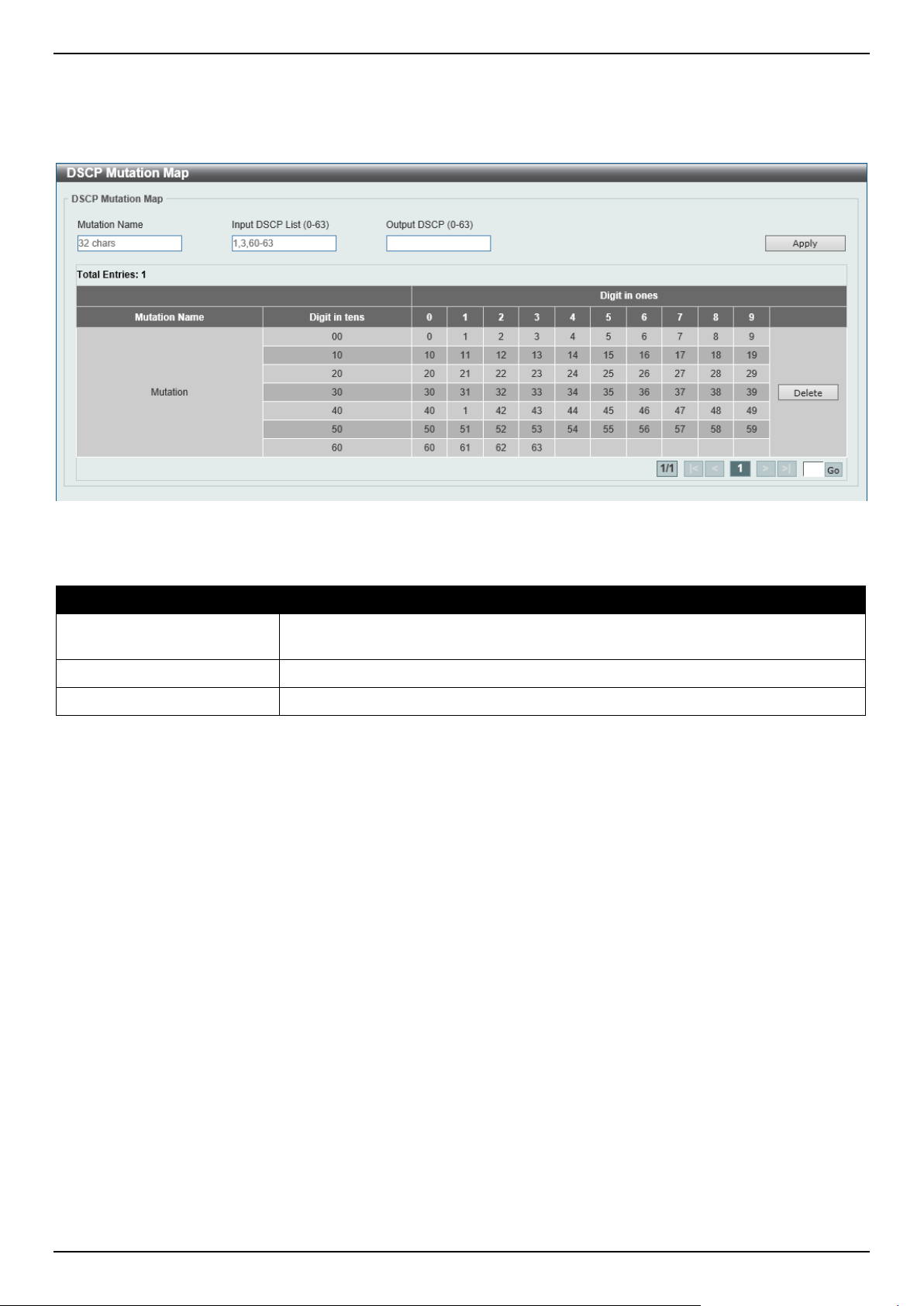
DGS-1520 Series Gigabit Ethernet Smart Managed Switch Web UI Reference Guide
349
different DSCP assignments. The DSCP-CoS map and DSCP-color map will still be based on the original DSCP of the
packet. All the subsequent operations will base on the mutated DSCP.
To view the following window, click QoS > Advanced Settings > DSCP Mutation Map, as shown below:
Figure 7-7 DSCP Mutation Map Window
The fields that can be configured are described below:
Parameter Description
Mutation Name
Enter the DSCP mutation map name here. This name can be up to 32 characters
long.
Input DSCP List
Enter the input DSCP list value here. This value must be between 0 and 63.
Output DSCP List
Enter the output DSCP list value here. This value must be between 0 and 63.
Click the Apply button to accept the changes made.
Click the Delete button to remove the specific entry.
Enter a page number and click the Go button to navigate to a specific page when multiple pages exist.
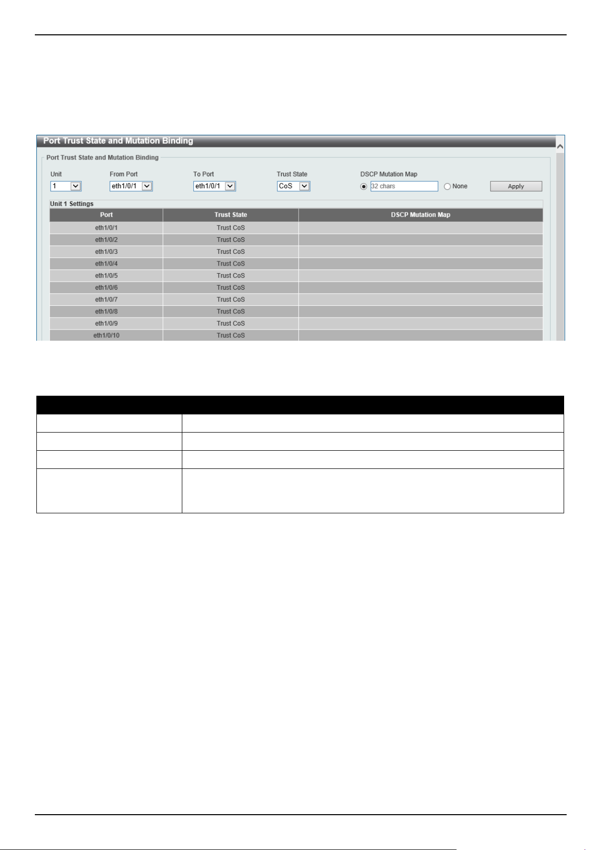
DGS-1520 Series Gigabit Ethernet Smart Managed Switch Web UI Reference Guide
350
Port Trust State and Mutation Binding
This window is used to display and configure the port trust state and mutation binding settings.
To view the following window, click QoS > Advanced Settings > Port Trust State and Mutation Binding, as shown
below:
Figure 7-8 Port Trust State and Mutation Binding Window
The fields that can be configured are described below:
Parameter Description
Unit
Select the Switch unit that will be used for this configuration here.
From Port - To Port
Select the range of ports that will be used for this configuration here.
Trust State Select the port trust state option here. Options to choose from are CoS and DSCP.
DSCP Mutation Map
Select and enter the DSCP mutation map name used here. This name can be up
to 32 characters long.
Select the None option to not allocate a DSCP mutation map to the port(s).
Click the Apply button to accept the changes made.
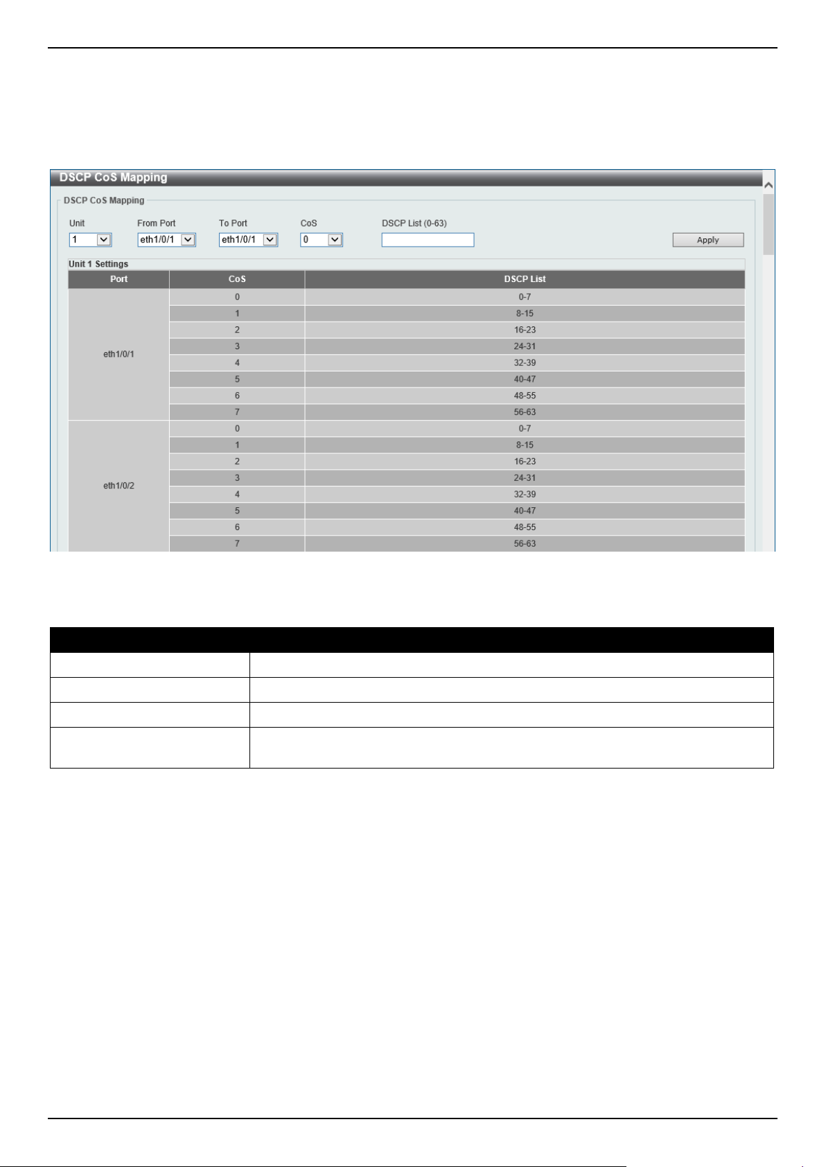
DGS-1520 Series Gigabit Ethernet Smart Managed Switch Web UI Reference Guide
351
DSCP CoS Mapping
This window is used to display and configure the DSCP CoS mapping settings.
To view the following window, click QoS > Advanced Settings > DSCP CoS Mapping, as shown below:
Figure 7-9 DSCP CoS Mapping Window
The fields that can be configured are described below:
Parameter Description
Unit
Select the Switch unit that will be used for this configuration here.
From Port - To Port
Select the range of ports that will be used for this configuration here.
CoS
Select the CoS value to map to the DSCP list. Options to choose from are 0 to 7.
DSCP List
Enter the DSCP list value to map to the CoS value here. This value must be
between 0 and 63.
Click the Apply button to accept the changes made.
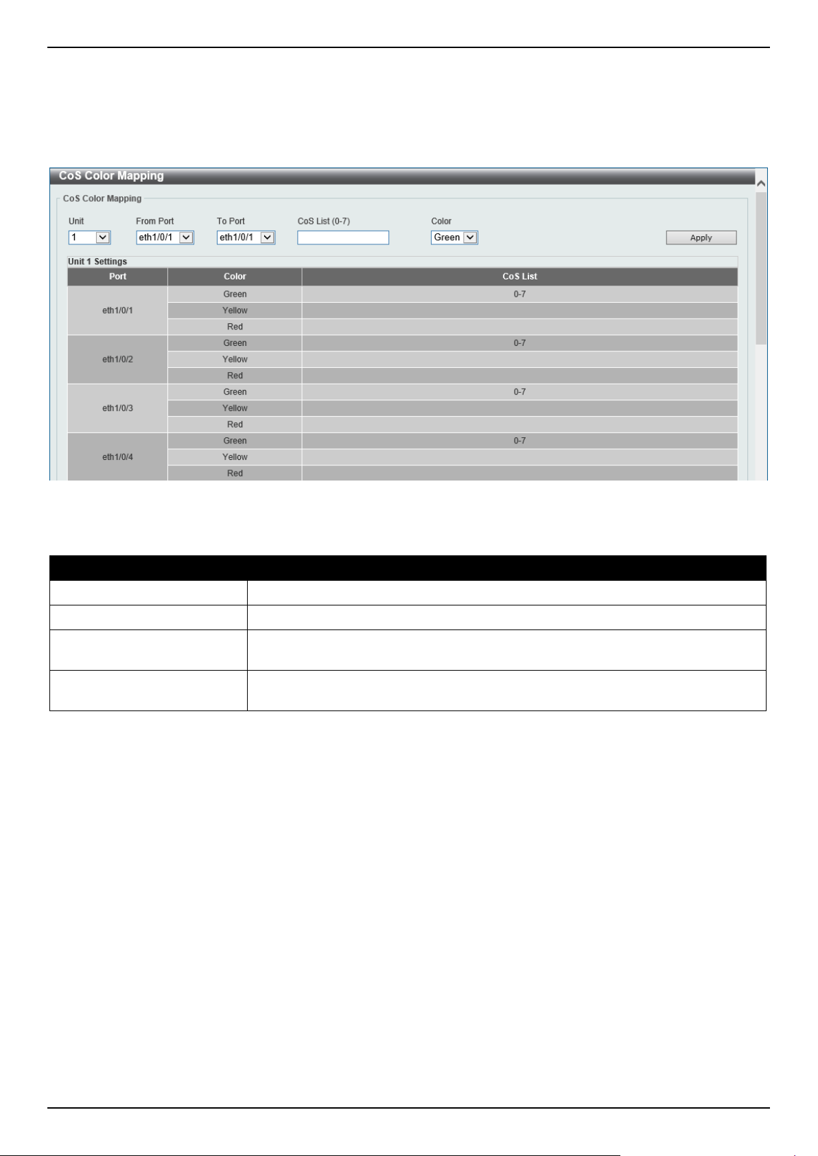
DGS-1520 Series Gigabit Ethernet Smart Managed Switch Web UI Reference Guide
352
CoS Color Mapping
This window is used to display and configure the CoS color mapping settings.
To view the following window, click QoS > Advanced Settings > CoS Color Mapping, as shown below:
Figure 7-10 CoS Color Mapping Window
The fields that can be configured are described below:
Parameter Description
Unit
Select the Switch unit that will be used for this configuration here.
From Port - To Port
Select the range of ports that will be used for this configuration here.
CoS List
Enter the CoS value that will be mapped to the color. This value must be between
0 and 7.
Color
Select the color option that will be mapped to the CoS value. Options to choose
from are Green, Yellow, and Red.
Click the Apply button to accept the changes made.
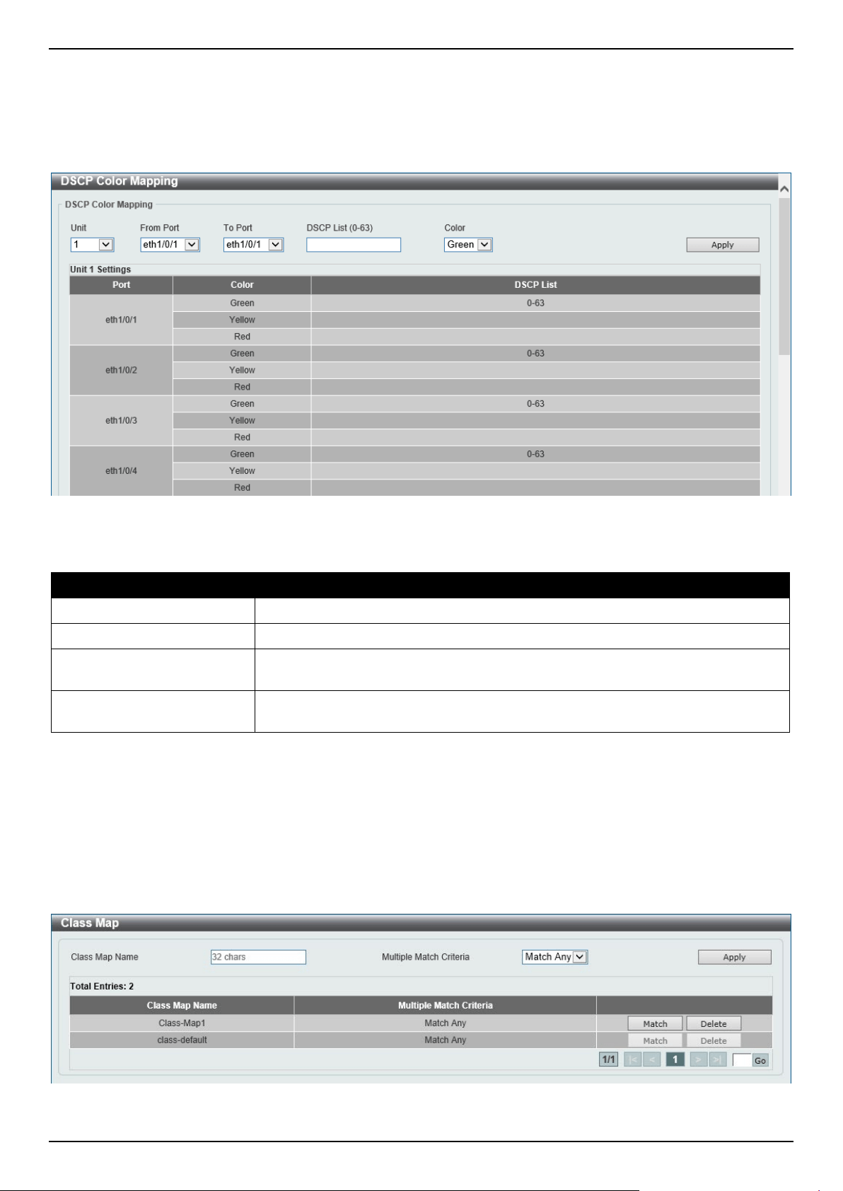
DGS-1520 Series Gigabit Ethernet Smart Managed Switch Web UI Reference Guide
353
DSCP Color Mapping
This window is used to display and configure the DSCP color mapping settings.
To view the following window, click QoS > Advanced Settings > DSCP Color Mapping, as shown below:
Figure 7-11 DSCP Color Mapping Window
The fields that can be configured are described below:
Parameter Description
Unit
Select the Switch unit that will be used for this configuration here.
From Port - To Port
Select the range of ports that will be used for this configuration here.
DSCP List
Enter the DSCP list value here that will be mapped to a color. This value must be
between 0 and 63.
Color
Select the color option that will be mapped to the DSCP value. Options to choose
from are Green, Yellow, and Red.
Click the Apply button to accept the changes made.
Class Map
This window is used to display and configure the class map settings.
To view the following window, click QoS > Advanced Settings > Class Map, as shown below:
Figure 7-12 Class Map Window
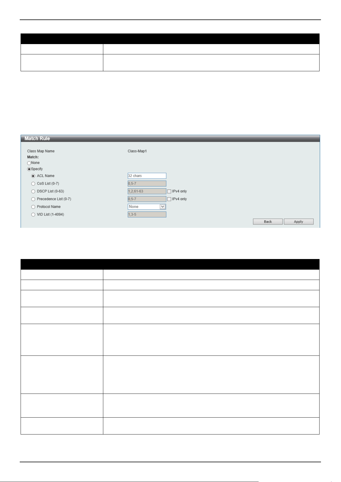
DGS-1520 Series Gigabit Ethernet Smart Managed Switch Web UI Reference Guide
354
The fields that can be configured are described below:
Parameter Description
Class Map Name
Enter the class map name here. This name can be up to 32 characters long.
Multiple Match Criteria Select the multiple match criteria option here. Options to choose from are Match
All and Match Any.
Click the Apply button to accept the changes made.
Click the Match button to configure the specific entry.
Click the Delete button to remove the specific entry.
Enter a page number and click the Go button to navigate to a specific page when multiple pages exist.
After clicking the Match button, the following page will be available.
Figure 7-13 Class Map (Match) Window
The fields that can be configured are described below:
Parameter Description
None
Select this option to match nothing to this class map.
Specify
Select the option to match something to this class map.
ACL Name
Select and enter the access list name that will be matched with this class map
here. This name can be up to 32 characters long.
CoS List
Select and enter the CoS list value that will be matched with this class map here.
This value must be between 0 and 7.
DSCP List
Select and enter the DSCP list value that will be matched with this class map here.
This value must be between 0 and 63.
Tick the IPv4 only option to match IPv4 packets only. If not specified, the match is
for both IPv4 and IPv6 packets.
Precedence List
Select and enter the precedence list value that will be matched with this class map
here. This value must be between 0 and 7.
Tick the IPv4 only option to match IPv4 packets only. If not specified, the match is
for both IPv4 and IPv6 packets. For IPv6 packets, the precedence is most three
significant bits of traffic class of IPv6 header.
Protocol Name
Select the protocol name that will be matched with the class map here. Options to
choose from are ARP, BGP, DHCP, DNS, EGP, FTP, IPv4, IPv6, NetBIOS, NFS,
NTP, OSPF, PPPOE, RIP, RTSP, SSH, Telnet, and TFTP.
VID List
Select and enter the VLAN list value that will be matched with the class map here.
This value must be between 1 and 4094.
Click the Apply button to accept the changes made.
Click the Back button to discard the changes made and return to the previous page.
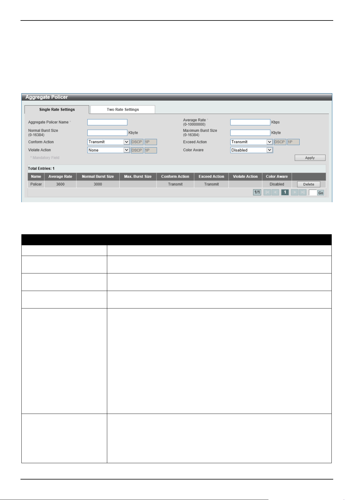
DGS-1520 Series Gigabit Ethernet Smart Managed Switch Web UI Reference Guide
355
Aggregate Policer
This window is used to display and configure the aggregate policer settings.
To view the following window, click QoS > Advanced Settings > Aggregate Policer and select the Single Rate
Settings tab, as shown below:
Figure 7-14 Aggregate Policer (Single Rate Setting) Window
The fields that can be configured are described below:
Parameter Description
Aggregate Policer Name
Enter the aggregate policer name here.
Average Rate
Enter the average rate value here. This value must be between 0 and 10000000
kbps.
Normal Burst Size
Enter the normal burst size value here. This value must be between 0 and 16384
Kbytes.
Maximum Burst Size
Enter the maximum burst size value here. This value must be between 0 and
16384 Kbytes.
Confirm Action
Select the confirm action here. The confirm action specifies the action to take on
green color packets. Options to choose from are:
• Drop - Specifies that the packet will be dropped.
• Set-DSCP-Transmit - Specifies to enter the IP DSCP value in the space
provided. This value sets the IP differentiated services code point (DSCP)
value and transmits the packet with the new IP DSCP value.
• Set-1P-Transmit - Specifies to enter the 1P transmit value in the space
provided. This value sets the 802.1p value and transmits the packet with the
new value.
• Transmit - Specifies that packets will be transmitted unaltered.
• Set-DSCP-1P - Specifies to enter the IP DSCP and 1P transmit values in
the spaces provided.
By default, the Transmit option is used. Packets are transmitted unaltered.
Exceed Action
Select the exceed action here. The exceed action specifies the action to take on
packets that exceed the rate limit. Options to choose from are:
• Drop - Specifies that the packet will be dropped.
• Set-DSCP-Transmit - Specifies to enter the IP DSCP value in the space
provided. This value sets the IP differentiated services code point (DSCP)
value and transmits the packet with the new IP DSCP value.
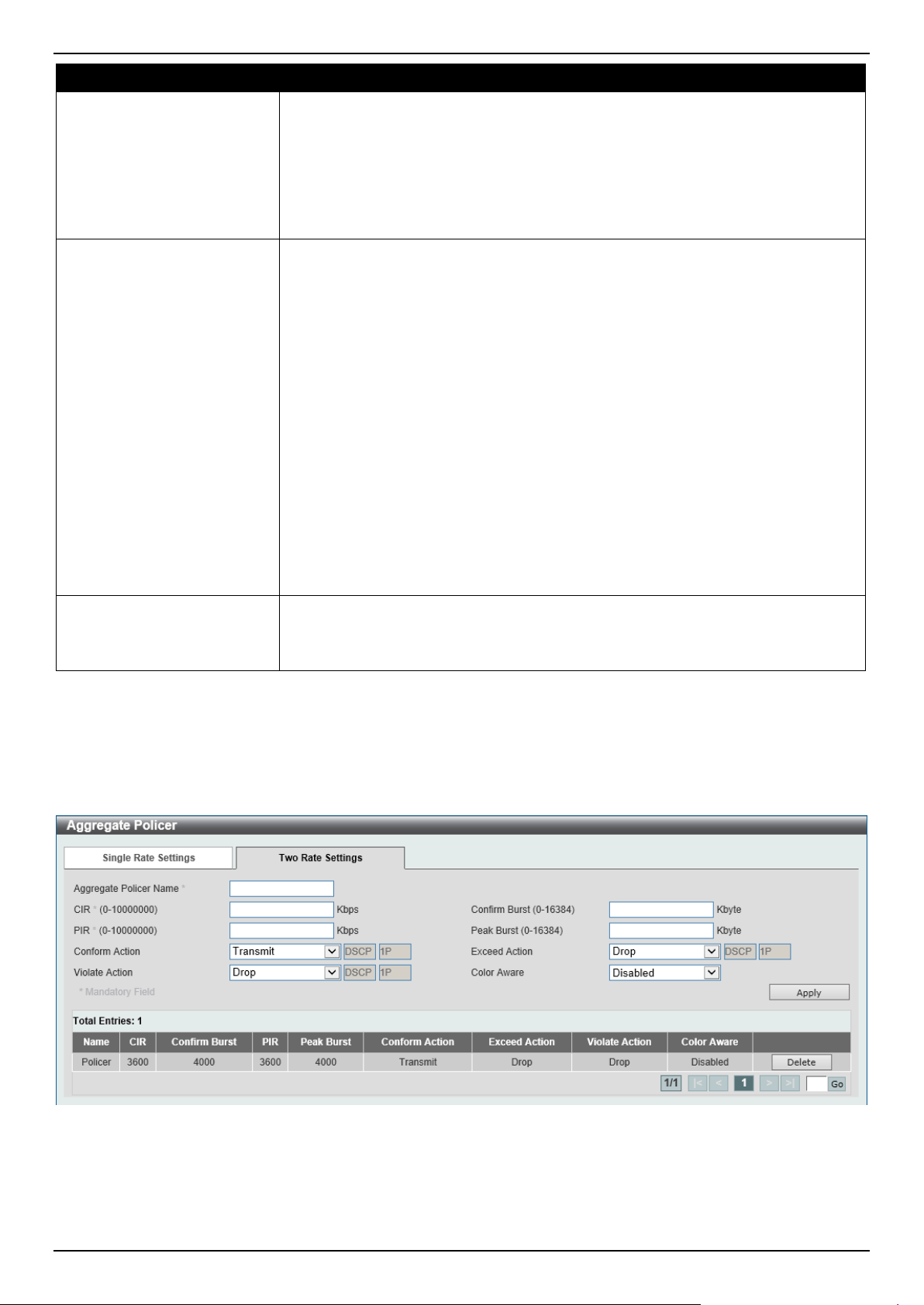
DGS-1520 Series Gigabit Ethernet Smart Managed Switch Web UI Reference Guide
356
Parameter Description
• Set-1P-Transmit - Specifies to enter the 1P transmit value in the space
provided. This value sets the 802.1p value and transmits the packet with the
new value.
• Transmit - Specifies that packets will be transmitted unaltered.
• Set-DSCP-1P - Specifies to enter the IP DSCP and 1P transmit values in
the spaces provided.
By default, the Drop option is used. Packets are dropped.
Violate Action
Select the violate action here. The violate action specifies the action to take on
packets that violate the normal and maximum burst sizes for singe rate policing. It
specifies the action to take for those packets that did not conform to both CIR and
PIR. Options to choose from are:
• None - Specifies that no action will be taken.
• Drop - Specifies that the packet will be dropped.
• Set-DSCP-Transmit - Specifies to enter the IP DSCP value in the space
provided. This value sets the IP differentiated services code point (DSCP)
value and transmits the packet with the new IP DSCP value.
• Set-1P-Transmit - Specifies to enter the 1P transmit value in the space
provided. This value sets the 802.1p value and transmits the packet with the
new value.
• Transmit - Specifies that packets will be transmitted unaltered.
• Set-DSCP-1P - Specifies to enter the IP DSCP and 1P transmit values in
the spaces provided.
By default, for a single rate policer, a single-rate two-color policer is created.
By default, for a two-rate policer, the Drop option is used. Packets are dropped.
Color Aware
Select the color aware option here. Options to choose from are:
• Enabled - Specifies that the policer work in the color-aware mode.
• Disabled - Specifies that the policer work in the colorblind mode.
Click the Apply button to accept the changes made.
Click the Delete button to remove the specific entry.
Enter a page number and click the Go button to navigate to a specific page when multiple pages exist.
To view the following window, select the Two Rate Settings tab, as shown below:
Figure 7-15 Aggregate Policer (Two Rate Settings) Window

DGS-1520 Series Gigabit Ethernet Smart Managed Switch Web UI Reference Guide
357
The fields that can be configured are described below:
Parameter Description
Aggregate Policer Name
Enter the aggregate policer name here.
CIR
Enter the Committed Information Rate (CIR) value here. This value must be
between 0 and 10000000 kbps. The committed packet rate is the first token bucket
for the two-rate metering.
Confirm Burst
Enter the confirm burst value here. This value must be between 0 and 16384
Kbytes. The confirm burst value specifies the burst size for the first token bucket in
kbps.
PIR
Enter the Peak Information Rate (PIR) value here. This value must be between 0
and 10000000 kbps. The peak information rate is the second token bucket for the
two-rate metering.
Peak Burst
Enter the peak burst value here. This value must be between 0 and 16384 Kbytes.
The peak burst value is the burst size for the second token bucket in kilobytes.
Confirm Action
Select the confirm action here. The confirm action specifies the action to take on
green color packets. Options to choose from are:
• Drop - Specifies that the packet will be dropped.
• Set-DSCP-Transmit - Specifies to enter the IP DSCP value in the space
provided. This value sets the IP differentiated services code point (DSCP)
value and transmits the packet with the new IP DSCP value.
• Set-1P-Transmit - Specifies to enter the 1P transmit value in the space
provided. This value sets the 802.1p value and transmits the packet with the
new value.
• Transmit - Specifies that packets will be transmitted unaltered.
• Set-DSCP-1P - Specifies to enter the IP DSCP and 1P transmit values in
the spaces provided.
By default, the Transmit option is used. Packets are transmitted unaltered.
Exceed Action
Select the exceed action here. The exceed action specifies the action to take on
packets that exceed the rate limit. Options to choose from are:
• Drop - Specifies that the packet will be dropped.
• Set-DSCP-Transmit - Specifies to enter the IP DSCP value in the space
provided. This value sets the IP differentiated services code point (DSCP)
value and transmits the packet with the new IP DSCP value.
• Set-1P-Transmit - Specifies to enter the 1P transmit value in the space
provided. This value sets the 802.1p value and transmits the packet with the
new value.
• Transmit - Specifies that packets will be transmitted unaltered.
• Set-DSCP-1P - Specifies to enter the IP DSCP and 1P transmit values in
the spaces provided.
By default, for a two rate policer, the Drop option is used. Packets are dropped.
Violate Action
Select the violate action here. The violate action specifies the action to take on
packets that violate the normal and maximum burst sizes for singe rate policing. It
specifies the action to take for those packets that did not conform to both CIR and
PIR. Options to choose from are:
• Drop - Specifies that the packet will be dropped.
• Set-DSCP-Transmit - Specifies to enter the IP DSCP value in the space
provided. This value sets the IP differentiated services code point (DSCP)
value and transmits the packet with the new IP DSCP value.
• Set-1P-Transmit - Specifies to enter the 1P transmit value in the space
provided. This value sets the 802.1p value and transmits the packet with the
new value.
• Transmit - Specifies that packets will be transmitted unaltered.
• Set-DSCP-1P - Specifies to enter the IP DSCP and 1P transmit values in
the spaces provided.
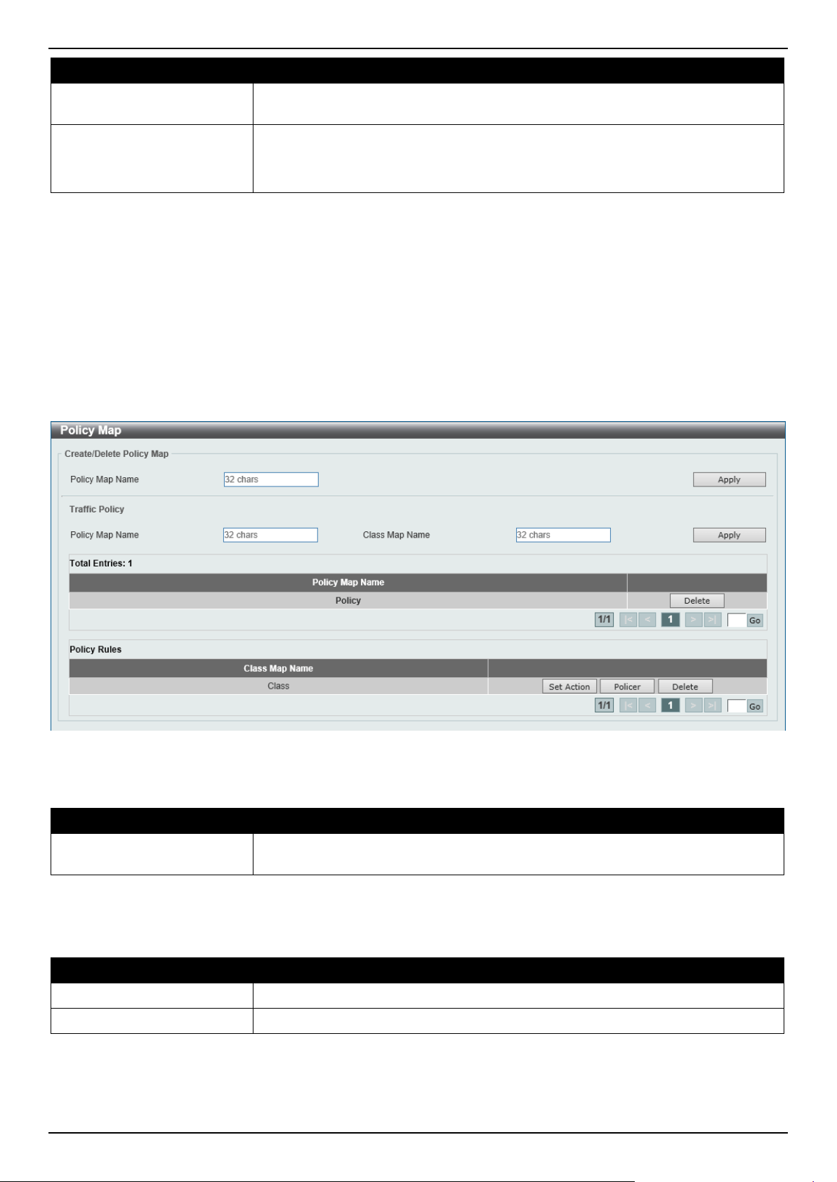
DGS-1520 Series Gigabit Ethernet Smart Managed Switch Web UI Reference Guide
358
Parameter Description
By default, for a single rate policer, a single-rate two-color policer is created.
By default, for a two-rate policer, the Drop option is used. Packets are dropped.
Color Aware
Select the color aware option here. Options to choose from are:
• Enabled - Specifies that the policer work in the color-aware mode.
• Disabled - Specifies that the policer work in the colorblind mode.
Click the Apply button to accept the changes made.
Click the Delete button to remove the specific entry.
Enter a page number and click the Go button to navigate to a specific page when multiple pages exist.
Policy Map
This window is used to display and configure the policy map settings.
To view the following window, click QoS > Advanced Settings > Policy Map, as shown below:
Figure 7-16 Policy Map Window
The fields that can be configured for Create/Delete Policy Map are described below:
Parameter Description
Policy Map Name
Enter the policy map name here that will be created or deleted. This name can be
up to 32 characters long.
Click the Apply button to accept the changes made.
The fields that can be configured for Traffic Policy are described below:
Parameter Description
Policy Map Name
Enter the policy map name here. This name can be up to 32 characters long.
Class Map Name
Enter the class map name here. This name can be up to 32 characters long.
Click the Apply button to accept the changes made.
Click the Delete button to remove the specific entry.
Enter a page number and click the Go button to navigate to a specific page when multiple pages exist.
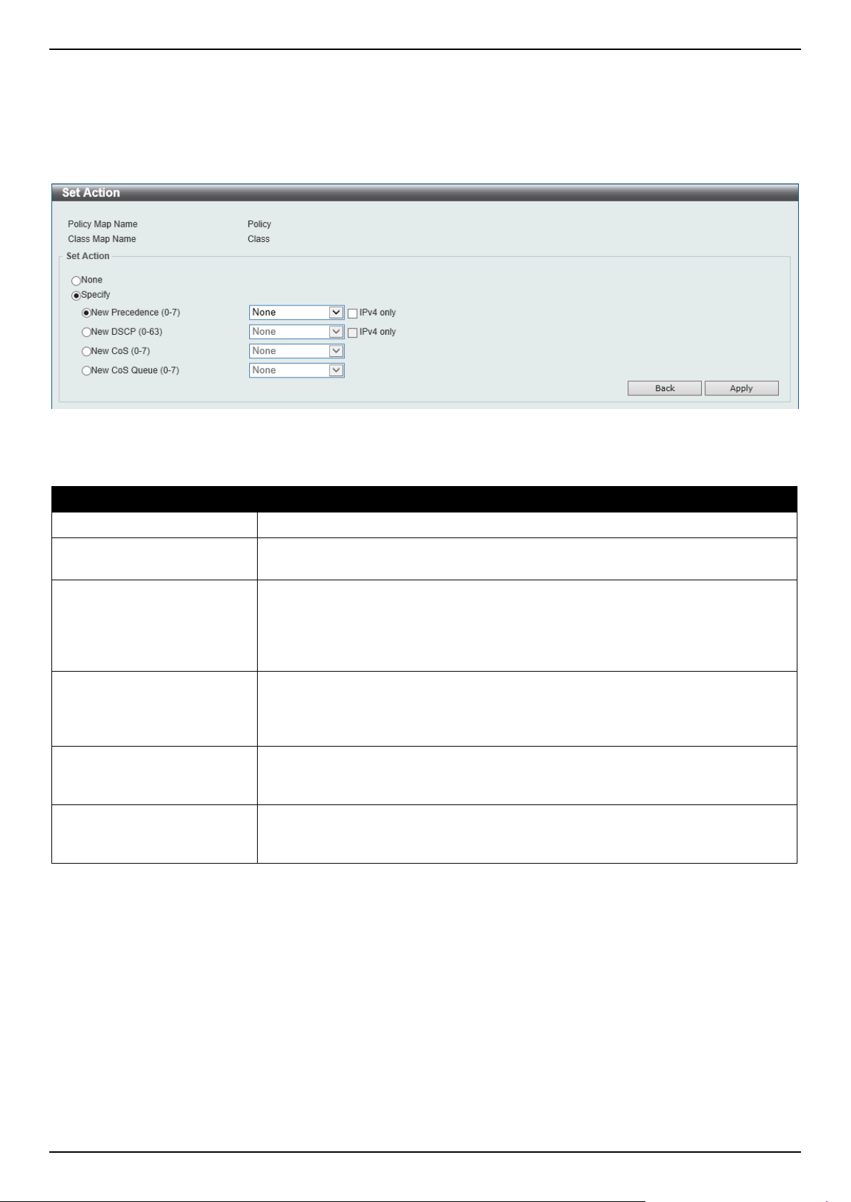
DGS-1520 Series Gigabit Ethernet Smart Managed Switch Web UI Reference Guide
359
Click the Set Action button to configure the set action settings for the specified entry.
Click the Policer button to configure the policer settings for the specified entry.
Enter a page number and click the Go button to navigate to a specific page when multiple pages exist.
After clicking the Set Action button, the following page will appear.
Figure 7-17 Policy Map (Set Action) Window
The fields that can be configured are described below:
Parameter Description
None
Select this option to specify that no action will be taken.
Specify
Select this option to specify that action will be taken based on the configurations
made.
New Precedence
Select the new precedence value for the packet here. The range is from 0 to 7.
Select the IPv4 only option to specify that IPv4 precedence will be marked only. If
not selected, then both IPv4 and IPv6 precedence will be marked. For IPv6
packets, the precedence is the most three significant bits of the traffic class of the
IPv6 header. Setting the precedence will not affect the CoS queue selection.
New DSCP
Select the new DSCP value for the packet here. The range is from 0 to 63. Select
the IPv4 only option to specify that the IPv4 DSCP will be marked only. If not
selected, then both the IPv4 and IPv6 DSCP will be marked. Setting the DSCP will
not affect the CoS queue selection.
New CoS
Select the new CoS value to the packet here. The range is from 0 to 7. Setting the
CoS will affect the CoS queue selection while the policy map is applied on the
ingress interface.
New Cos Queue
Select the new CoS queue value to the packets here. This will overwrite the
original CoS queue selection. Setting the CoS queue will not take effect if the
policy map is applied for the egress flow on the interface.
Click the Back button to return to the previous window.
Click the Apply button to accept the changes made.
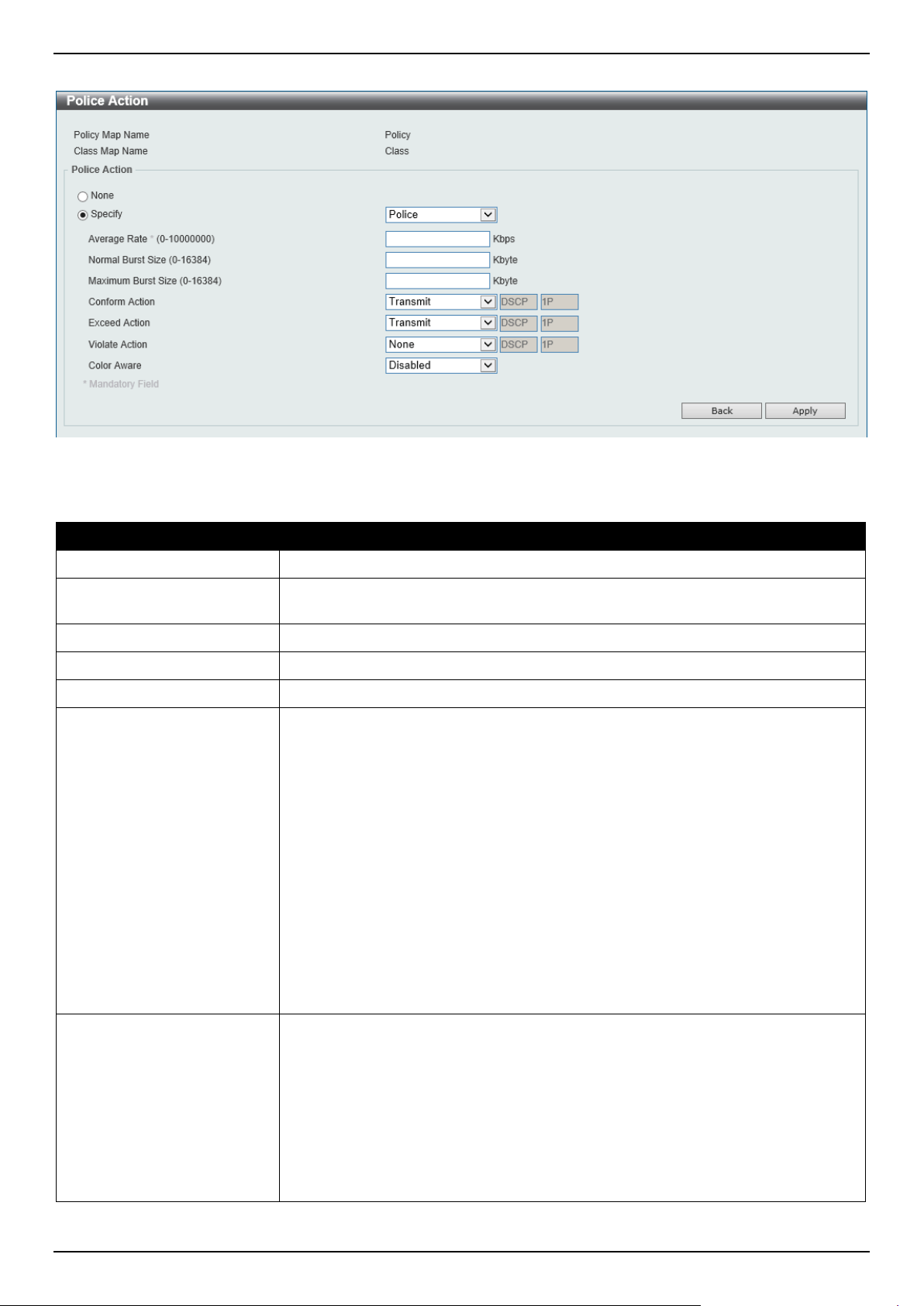
DGS-1520 Series Gigabit Ethernet Smart Managed Switch Web UI Reference Guide
360
After clicking the Policer button, the following page will appear.
Figure 7-18 Policy Map (Policer) Window
The fields that can be configured are described below:
Parameter Description
None
Select this option to specify that no policer settings will be configured for this entry.
Specify
Select this option to specify that the following policer settings will be applied to this
entry.
Average Rate
Enter the average rate value here. The range is from 0 to 10000000 Kbps.
Normal Burst Size
Enter the normal burst size value here. The range is from 0 to 16384 Kbps.
Maximum Burst Size
Enter the maximum burst size value here. The range is from 0 to 16384 Kbps.
Conform Action
Select the conform action that will be taken here. This action will be taken on green
color packets. Option to choose from are:
• Drop - Specifies that the conform action is to drop the packet.
• Set-DSCP-Transmit - Specifies that the conform action is to modify the
DSCP value and then to transmit the packet with the new DSCP value.
Enter the new DSCP value in the space provided.
• Set-1P-Transmit - Specifies that the conform action is to modify the 802.1p
value and then to transmit the packet with the new 802.1p value. Enter the
new 802.1p value in the space provided.
• Transmit - Specifies that the conform action is to transmit the packet
unmodified.
• Set-DSCP-1P - Specifies that the conform action is to modify the DSCP and
802.1p values and then to transmit the packet with the new DSCP and
802.1p values. Enter the new DSCP and 802.1p values in the spaces
provided.
Exceed Action
Select the exceed action that will be taken here. This action will be taken on yellow
color packets that exceed the rate limit. Option to choose from are:
• Drop - Specifies that the exceed action is to drop the packet.
• Set-DSCP-Transmit - Specifies that the exceed action is to modify the
DSCP value and then to transmit the packet with the new DSCP value.
Enter the new DSCP value in the space provided.
• Set-1P-Transmit - Specifies that the exceed action is to modify the 802.1p
value and then to transmit the packet with the new 802.1p value. Enter the
new 802.1p value in the space provided.
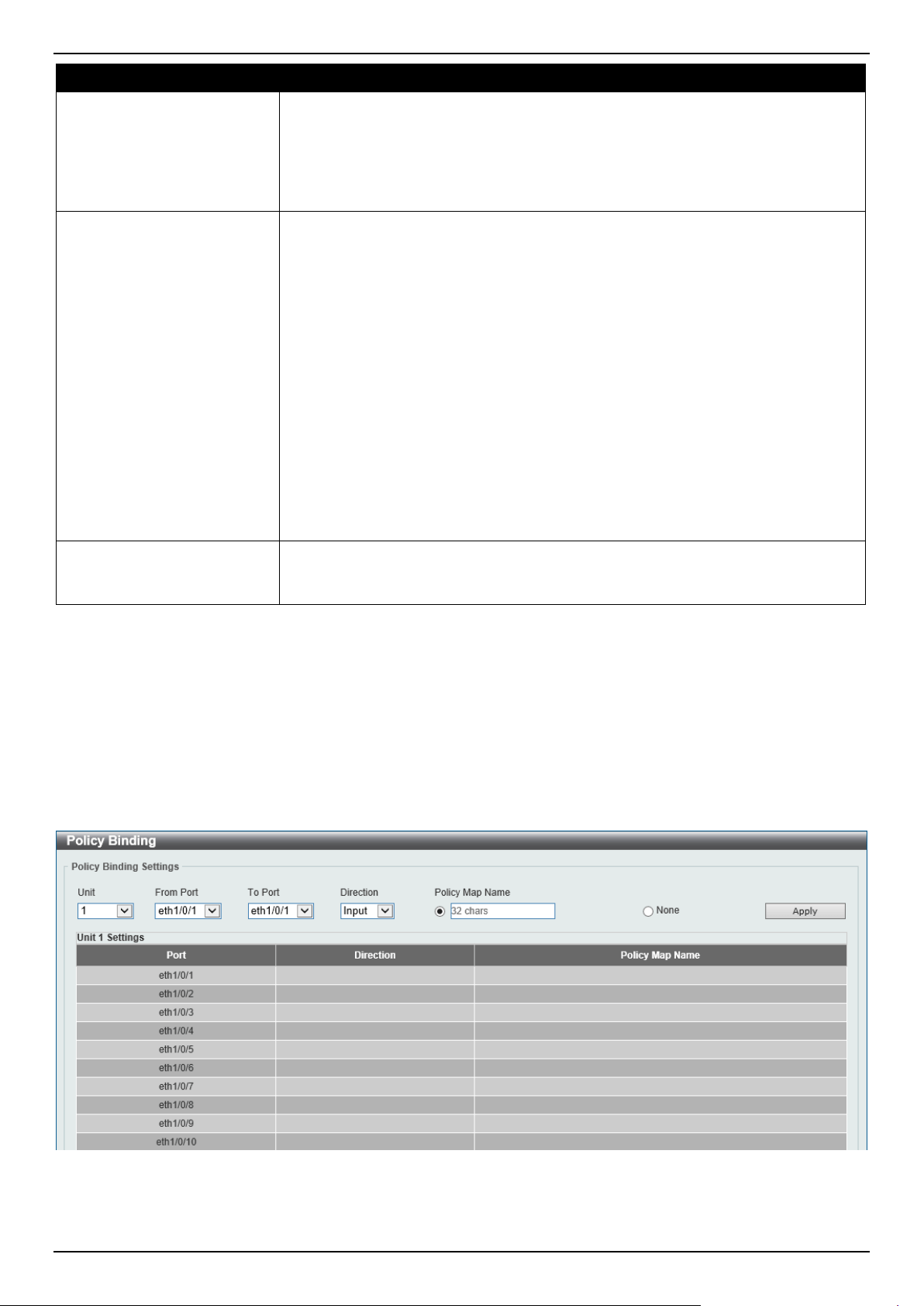
DGS-1520 Series Gigabit Ethernet Smart Managed Switch Web UI Reference Guide
361
Parameter Description
• Transmit - Specifies that the exceed action is to transmit the packet
unmodified.
• Set-DSCP-1P - Specifies that the exceed action is to modify the DSCP and
802.1p values and then to transmit the packet with the new DSCP and
802.1p values. Enter the new DSCP and 802.1p values in the spaces
provided.
Violate Action
Select the violate action that will be taken here. This action will be taken on red
color packets. Option to choose from are:
• None - Specifies that no violate action will be taken.
• Drop - Specifies that the violate action is to drop the packet.
• Set-DSCP-Transmit - Specifies that the violate action is to modify the
DSCP value and then to transmit the packet with the new DSCP value.
Enter the new DSCP value in the space provided.
• Set-1P-Transmit - Specifies that the violate action is to modify the 802.1p
value and then to transmit the packet with the new 802.1p value. Enter the
new 802.1p value in the space provided.
• Transmit - Specifies that the violate action is to transmit the packet
unmodified.
• Set-DSCP-1P - Specifies that the violate action is to modify the DSCP and
802.1p values and then to transmit the packet with the new DSCP and
802.1p values. Enter the new DSCP and 802.1p values in the spaces
provided.
Color Aware
Select to enable or disable the color aware feature here. When disabled, the
policer works in the colorblind mode. When enabled, the policer works in the color-
aware mode.
Click the Back button to return to the previous window.
Click the Apply button to accept the changes made.
Policy Binding
This window is used to display and configure the policy binding settings.
To view the following window, click QoS > Advanced Settings > Policy Binding, as shown below:
Figure 7-19 Policy Binding Window
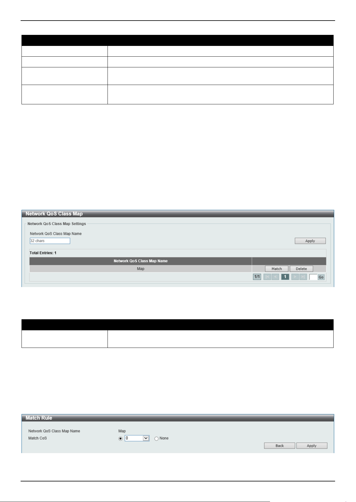
DGS-1520 Series Gigabit Ethernet Smart Managed Switch Web UI Reference Guide
362
The fields that can be configured are described below:
Parameter Description
Unit
Select the Switch unit that will be used for this configuration here.
From Port - To Port
Select the range of ports that will be used for this configuration here.
Direction Select the direction option here. Options to choose from are Input and Output.
Input specified ingress traffic and output specifies egress traffic.
Policy Map Name
Enter the policy map name here. This name can be up to 32 characters long.
Select the None option to not tie a policy map to this entry.
Click the Apply button to accept the changes made.
QoS PFC
Network QoS Class Map
This window is used to display and configure the network Quality of Service (QoS) Priority-based Flow Control (PFC)
class map settings.
To view the following window, click QoS > QoS PFC > Network QoS Class Map, as shown below:
Figure 7-20 Network QoS Class Map Window
The fields that can be configured are described below:
Parameter Description
Network QoS Class Map
Name
Enter the network QoS class map name to be associated with a traffic policy here.
This name can be up to 32 characters long.
Click the Apply button to accept the changes made.
Click the Match button to configure the match rule settings for the map name.
Click the Delete button to delete the specified entry.
Enter a page number and click the Go button to navigate to a specific page when multiple pages exist.
After clicking the Match button, the following page will appear.
Figure 7-21 Network QoS Class Map (Match) Window
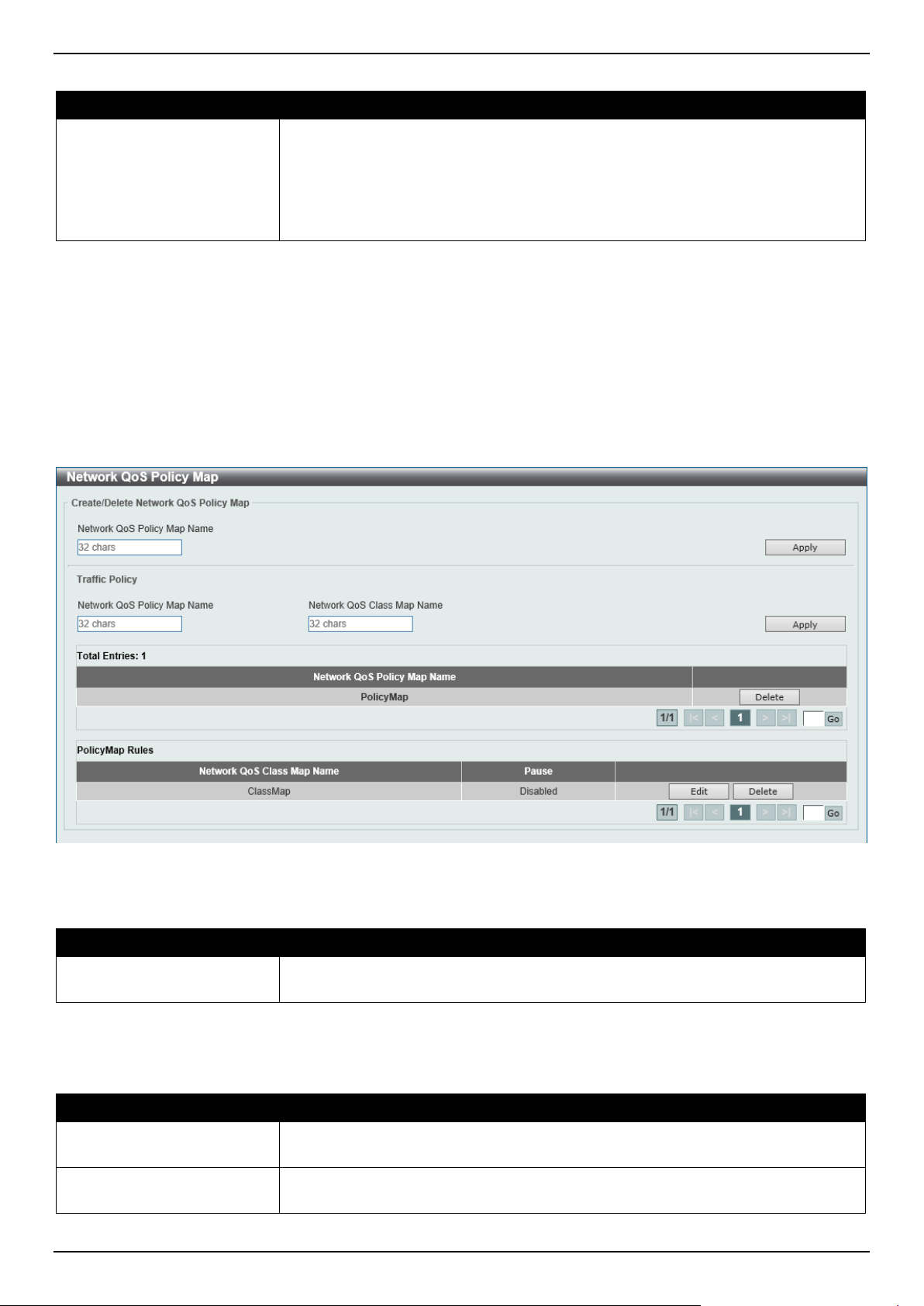
DGS-1520 Series Gigabit Ethernet Smart Managed Switch Web UI Reference Guide
363
The fields that can be configured are described below:
Parameter Description
Match CoS
Select the IEEE 802.1Q Class of Service (CoS) value to be matched here. The
range is from 0 to 7. When a packet is received, the packet will be given an
internal CoS. This internal CoS is used to select the transmit queue based on the
CoS to queue map. The CoS queue with a higher number will receive a higher
priority.
Select to None option to disable the matching of CoS values.
Click the Back button to return to the previous window.
Click the Apply button to accept the changes made.
Network QoS Policy Map
This window is used to display and configure the network QoS policy map settings.
To view the following window, click QoS > QoS PFC > Network QoS Policy Map, as shown below:
Figure 7-22 Network QoS Policy Map Window
The fields that can be configured in Create/Delete Network QoS Policy Map are described below:
Parameter Description
Network QoS Policy Map
name
Enter the network QoS policy map name here. This name can be up to 32
characters long.
Click the Apply button to accept the changes made.
The fields that can be configured in Traffic Policy are described below:
Parameter Description
Network QoS Policy Map
Name
Enter the network QoS policy map name here that will be associated with the class
map. This name can be up to 32 characters long.
Network QoS Class Map
Name
Enter the network QoS class map name here that will be associated with the policy
map. This name can be up to 32 characters long.
Click the Apply button to accept the changes made.
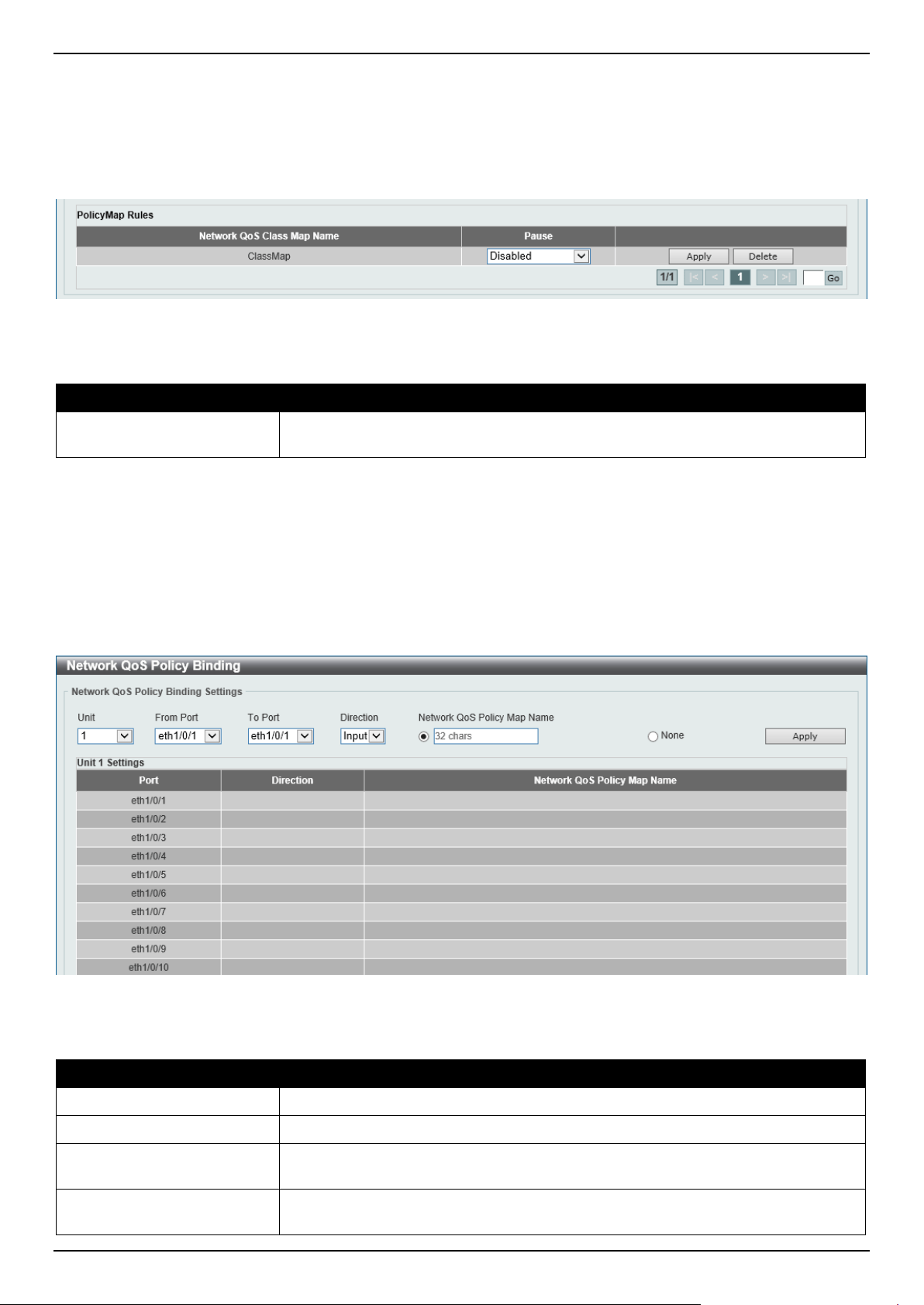
DGS-1520 Series Gigabit Ethernet Smart Managed Switch Web UI Reference Guide
364
Click the Edit button to modify the specified entry.
Click the Delete button to delete the specified entry.
Enter a page number and click the Go button to navigate to a specific page when multiple pages exist.
After clicking the Edit button, the following page will appear.
Figure 7-23 Network QoS Policy Map (Edit) Window
The fields that can be configured are described below:
Parameter Description
Pause
Select to enable or disable the pause feature here. This feature is used to enable
PFC on a class referenced in a type network QoS policy map.
Click the Apply button to accept the changes made.
Network QoS Policy Binding
This window is used to display and configure the network QoS policy binding settings.
To view the following window, click QoS > QoS PFC > Network QoS Policy Binding, as shown below:
Figure 7-24 Network QoS Policy Binding Window
The fields that can be configured are described below:
Parameter Description
Unit
Select the Switch unit ID that will be used here.
From Port - To Port
Select the Switch port range that will be used here.
Direction Select the Input direction here. This specifies to apply the policy map for ingress
flow on the interface.
Network QoS Policy Map
Name
Enter the network QoS policy map name here. This name can be up to 32
characters long.
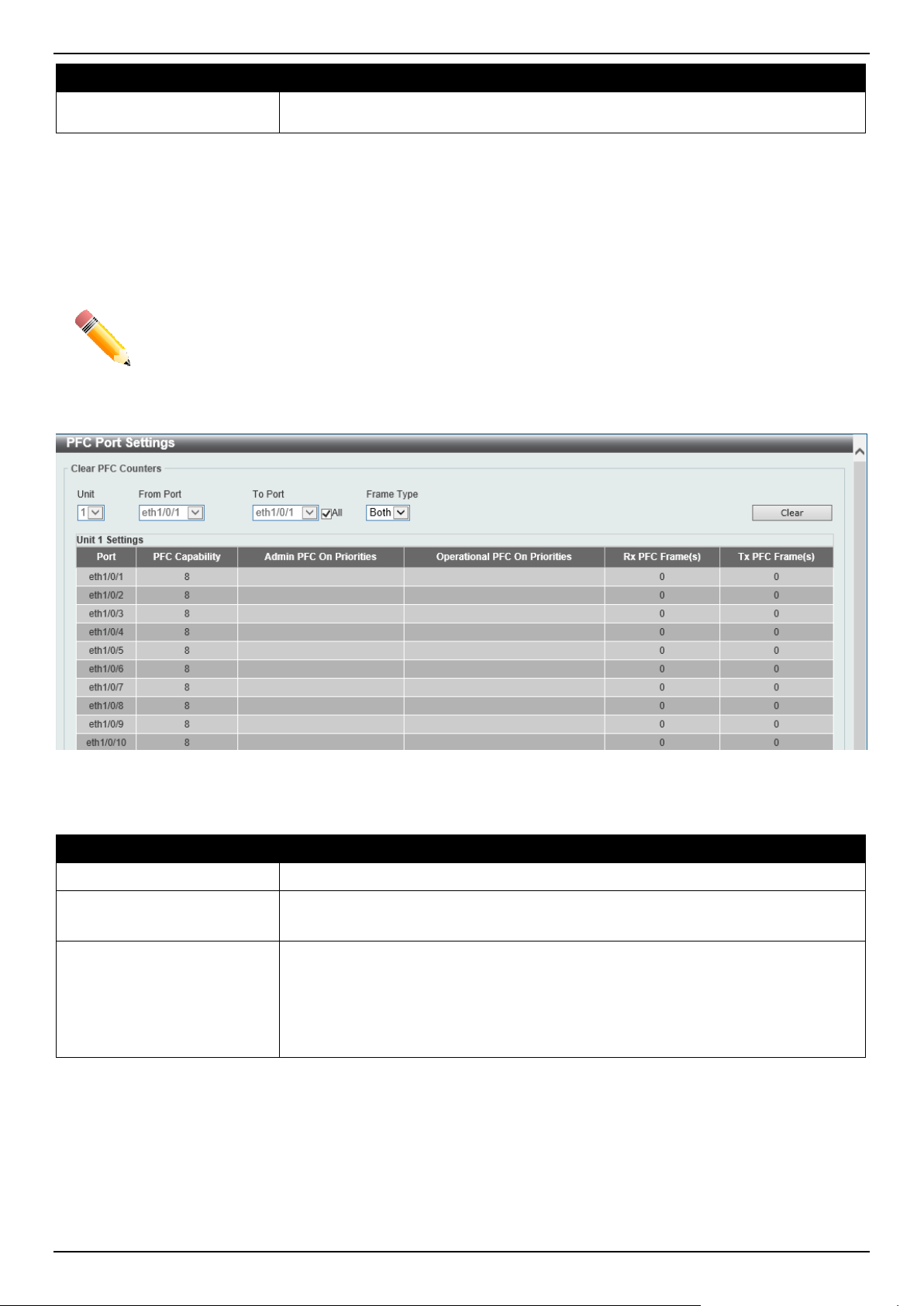
DGS-1520 Series Gigabit Ethernet Smart Managed Switch Web UI Reference Guide
365
Parameter Description
Select the None option to not associate this configuration with a network QoS
policy map.
Click the Apply button to accept the changes made.
PFC Port Settings
This window is used to display and configure the Priority-based Flow Control (PFC) port settings.
NOTE: The Priority Flow Control (PFC) feature can only be enabled and used on the 10G ports.
To view the following window, click QoS > QoS PFC > PFC Port Settings, as shown below:
Figure 7-25 PFC Port Settings Window
The fields that can be configured in Clear PFC Counters are described below:
Parameter Description
Unit
Select the Switch unit ID that will be used here.
From Port - To Port
Select the Switch port range that will be used here.
Select the All option to specify that all ports will be used here.
Frame Type
Select the frame type that will be cleared here. Options to choose from are:
• RX - Specifies to clear the counters of received PFC frames.
• TX - Specifies to clear the counters of transmitted PFC frames.
• Both - Specifies to clear the counters of received and transmitted PFC
frames.
Click the Clear button to clear the counters based on the selections made.
WRED
Weighted Random Early Detection (WRED) is another implementation for QoS that will help the overall throughput for
your QoS queues. Based on the egress queue of the QoS function set on the Switch, this method will analyze these
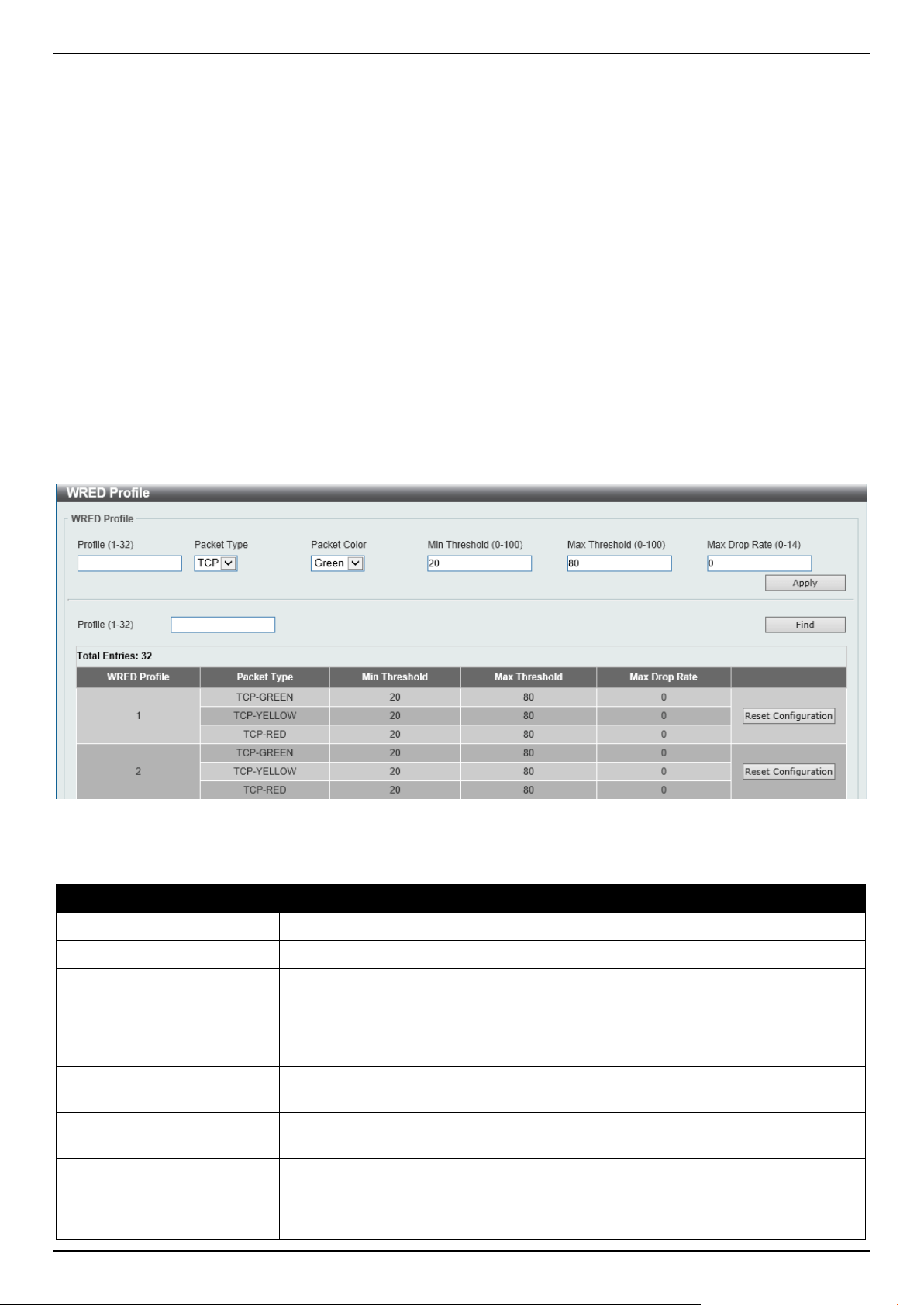
DGS-1520 Series Gigabit Ethernet Smart Managed Switch Web UI Reference Guide
366
packets and their QoS queue to determine if there will be an overflow of packets entering the QoS queues and
consequentially, minimize the packet flow into these queues by dropping random packets.
WRED employs two methods of avoiding congestion within the QoS queue.
• Every QoS queue has a minimum and a maximum level for acceptance of packets. Once the maximum
threshold has been reached for this queue, the Switch will begin discarding all ingress packets, this minimizing
the allotted bandwidth for QoS. When below the minimum threshold, the Switch will accept all ingress packets.
• When the ingress packets are somewhere between the maximum and minimum queue, the Switch will use a
slope probability function to determine a random method of dropping packets based on the maximum drop rate
which specifies the drop probability when the queues reach maximum threshold. If queues are closer to the
maximum threshold, the Switch will increase the discarding of random packets to even out the flow to the
queues and avoid overflows to higher priority queues.
WRED Profile
This window is used to display and configure the Weighted Random Early Detection (WRED) profile settings.
To view the following window, click QoS > WRED > WRED Profile, as shown below:
Figure 7-26 WRED Profile Window
The fields that can be configured are described below:
Parameter Description
Profile
Enter the WRED profile ID here. The range is from 1 to 32.
Packet Type
Specifies that the packet type is TCP.
Packet Colour
Select the packet color here. Options to choose from are:
• Green - Specifies the WRED drop parameters for green packets to be set.
• Yellow - Specifies the WRED drop parameters for yellow packets to be set.
• Red - Specifies the WRED drop parameters for red packets to be set.
Min Threshold
Enter the minimum threshold value here that will be used to start WRED dropping.
The range is from 0 to 100.
Max Threshold
Enter the maximum threshold value here over which WRED will drop all packets
destined for this queue. The range is from 0 to 100.
Max Drop Rate
Enter the maximum drop-rate value here. The range is from 0 to 14. This feature
specifies the drop probability when the average queue size reaches the maximum
threshold. When this value is zero, then the packet will not be dropped or
remarked for ECN.
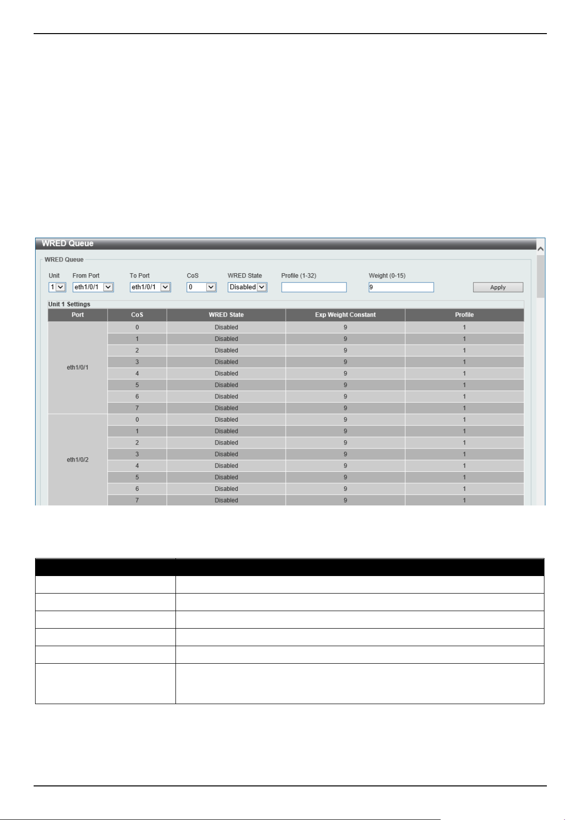
DGS-1520 Series Gigabit Ethernet Smart Managed Switch Web UI Reference Guide
367
Click the Apply button to accept the changes made.
Click the Find button to locate a specific entry based on the information entered.
Click the Reset Configuration button to reset the configuration on the specified entry.
WRED Queue
This window is used to display and configure the WRED queue settings. WRED drops packets, based on the average
queue size exceeding a specific threshold, to indicate congestion. Explicit Congestion Notification (ECN) is an
extension to WRED in that ECN marks packets instead of dropping them when the average queue size exceeds a
specific threshold value. When configuring the WRED ECN feature, routers and end hosts would use this marking as
a signal that the network is congested and slow down sending packets.
To view the following window, click QoS > WRED > WRED Queue, as shown below:
Figure 7-27 WRED Queue Window
The fields that can be configured are described below:
Parameter Description
Unit
Select the Switch unit ID that will be used here.
From Port - To Port
Select the Switch port range that will be used here.
CoS
Select the CoS value here. The range is from 0 to 7.
WRED State
Select to enable or disable the WRED feature state on the specified port(s) here.
Profile
Enter the WRED profile ID here. The range is from 1 to 32.
Weight
Enter the exponential weight value here. The range is from 0 to 15. This feature is
used to configure the WRED exponential weight factor for the average queue size
calculation for the queue.
Click the Apply button to accept the changes made.
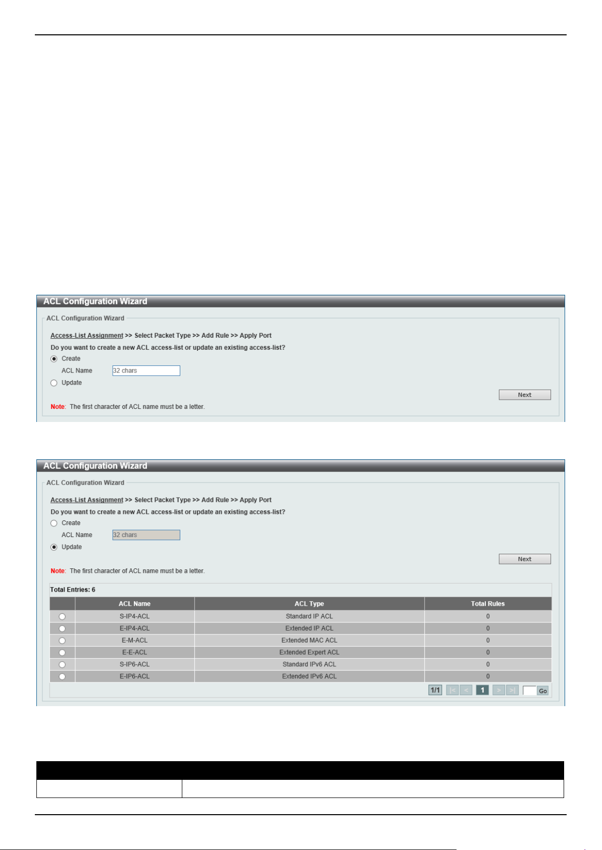
DGS-1520 Series Gigabit Ethernet Smart Managed Switch Web UI Reference Guide
368
8. Access Control List (ACL)
ACL Configuration Wizard
ACL Access List
ACL Interface Access Group
ACL VLAN Access Map
ACL VLAN Filter
CPU ACL
ACL Configuration Wizard
This window is used to guide the user to create a new ACL access list or configure an existing ACL access list.
Step 1 - Create/Update
To view the following window, click ACL > ACL Configuration Wizard, as shown below:
Figure 8-1 ACL Configuration Wizard (Create) Window
Figure 8-2 ACL Configuration Wizard (Update) Window
The fields that can be configured are described below:
Parameter Description
Create
Select this option to create a new ACL access list using the configuration wizard.
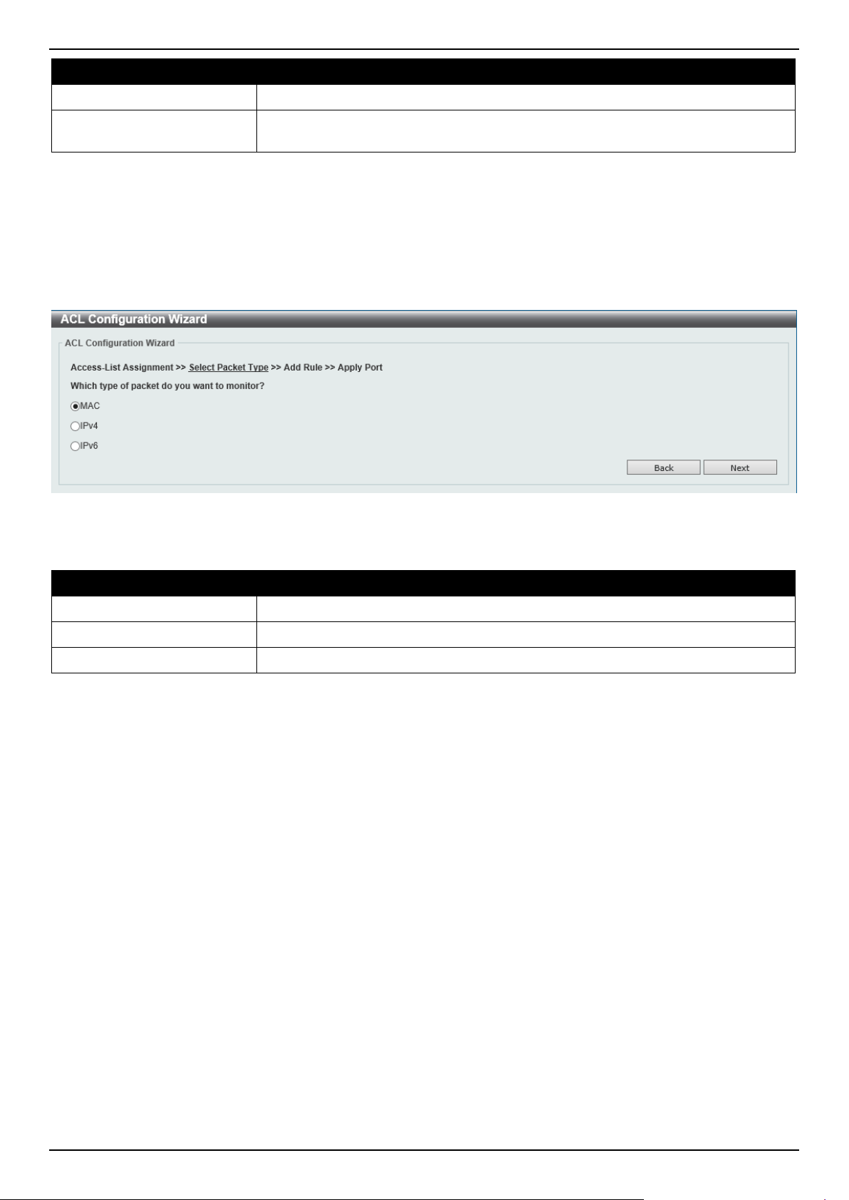
DGS-1520 Series Gigabit Ethernet Smart Managed Switch Web UI Reference Guide
369
Parameter Description
ACL Name
Enter the new ACL name here. This name can be up to 32 characters long.
Update
Select this option to update an existing ACL access list. Select the existing ACL in
the table to process with the update.
Click the Next button to continue to the next step.
Enter a page number and click the Go button to navigate to a specific page when multiple pages exist.
Step 2 - Select Packet Type
After clicking the Next button, the following window will appear.
Figure 8-3 ACL Configuration Wizard (Create, Packet Type) Window
The fields that can be configured are described below:
Parameter Description
MAC
Select to create/update a MAC ACL.
IPv4
Select to create/update an IPv4 ACL.
IPv6
Select to create/update an IPv6 ACL.
Click the Back button to return to the previous step.
Click the Next button to continue to the next step.
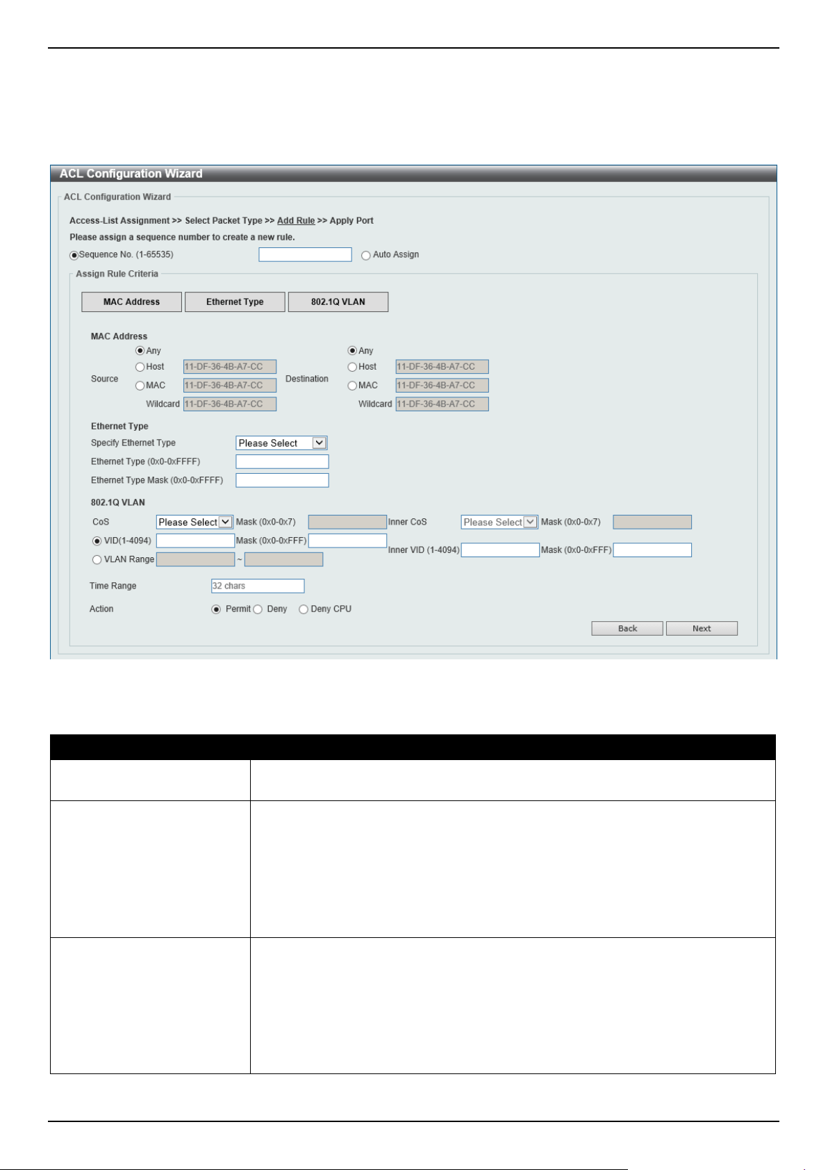
DGS-1520 Series Gigabit Ethernet Smart Managed Switch Web UI Reference Guide
370
Step 3 - Add Rule
Extended MAC ACL
Selecting to Create or Update a MAC ACL and click the Next button to view the following window:
Figure 8-4 ACL Configuration Wizard (Extended MAC ACL) Window
The fields that can be configured are described below:
Parameter Description
Sequence No.
Enter the ACL rule number here. This value must be between 1 and 65535. Select
Auto Assign to automatically generate an ACL rule number for this entry.
Source
Select and enter the source MAC address information here. Options to choose
from are:
• Any - Any source traffic will be evaluated according to the conditions of this
rule.
• Host - Enter the source host MAC address here.
• MAC - The Wildcard option will be available. Enter the source MAC
address and wildcard value in the spaces provided.
Destination
Select and enter the destination MAC address information here. Options to choose
from are:
• Any - Any destination traffic will be evaluated according to the conditions of
this rule.
• Host - Enter the destination host MAC address here.
• MAC - The Wildcard option will be available. Enter the destination MAC
address and wildcard value in the spaces provided.

DGS-1520 Series Gigabit Ethernet Smart Managed Switch Web UI Reference Guide
371
Parameter Description
Specify Ethernet Type Select the Ethernet type option here. Options to choose from are aarp, appletalk,
decent-iv, etype-6000, etype-8042, lat, lavc-sca, mop-console, mop-dump,
vines-echo, vines-ip, xns-idp, and arp.
Ethernet Type
Enter the Ethernet type hexadecimal value here. This value must be between 0x0
and 0xFFFF. When any Ethernet type profile is selected in the Specify Ethernet
Type drop-down list, the appropriate hexadecimal value will automatically be
entered.
Ethernet Type Mask
Enter the Ethernet type mask hexadecimal value here. This value must be
between 0x0 and 0xFFFF. When any Ethernet type profile is selected in the
Specify Ethernet Type drop-down list, the appropriate hexadecimal value will
automatically be entered.
CoS Select the CoS value that will be used here. The range is from 0 to 7.
• Mask - Enter the CoS mask value here. The range is from 0x0 to 0x7.
Inner CoS
After selecting the CoS value, select the inner CoS value that will be used here.
The range is from 0 to 7.
• Mask - Enter the inner CoS mask value here. The range is from 0x0 to 0x7.
VID
Enter the VLAN ID that will be associated with this ACL rule here. The range is
from 1 to 4094.
• Mask - Enter the VLAN ID mask value here. The range is from 0x0 to
0xFFF.
Inner VID
Enter the inner VLAN ID that will be associated with this ACL rule here. The range
is from 1 to 4094.
• Mask - Enter the inner VLAN ID mask value here. The range is from 0x0 to
0xFFF.
VLAN Range
Select and enter the VLAN range that will be associated with this ACL rule here.
Enter the starting and ending VLANs in the spaces provided. The range is from 1
to 4094.
Time Range
Enter the name of the time range profile that will be used in this ACL rule here.
This name can be up to 32 characters long.
Action Select the action that this rule will take here. Options to choose from are Permit,
Deny, and Deny CPU.
Click the Back button to return to the previous step.
Click the Next button to continue to the next step.
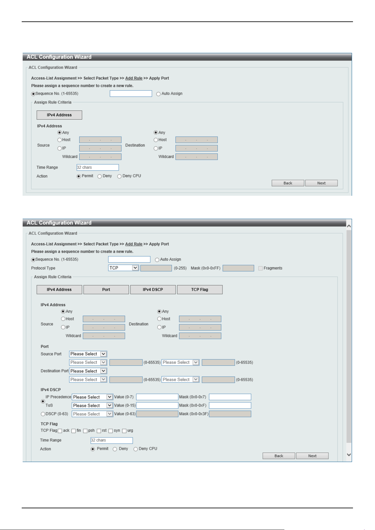
DGS-1520 Series Gigabit Ethernet Smart Managed Switch Web UI Reference Guide
372
Extended/Standard IPv4 ACL
Selecting to Create or Update an IPv4 ACL and click the Next button to view the following window:
Figure 8-5 ACL Configuration Wizard (Standard IPv4 ACL) Window
Figure 8-6 ACL Configuration Wizard (Extended IPv4 ACL) Window

DGS-1520 Series Gigabit Ethernet Smart Managed Switch Web UI Reference Guide
373
The fields that can be configured are described below:
Parameter Description
Sequence No.
Enter the ACL rule number here. This value must be between 1 and 65535. Select
Auto Assign to automatically generate an ACL rule number for this entry.
Protocol Type Select the protocol type option here. Options to choose from are TCP, UDP, ICMP,
EIGRP (88), ESP (50), GRE (47), IGMP (2), OSPF (89), PIM (103), VRRP (112),
IP-in-IP (94), PCP (108), Protocol ID, and None.
• Value - The protocol ID can also manually be entered here. The range is
from 0 to 255.
• Mask - After selecting the Protocol ID option, manually enter the protocol
mask value here. The range is from 0x0 to 0xFF.
• Fragments - Select this option to include packet fragment filtering.
The fields that can be configured in Assign rule criteria are described below:
Parameter Description
Source
Select and enter the source information here. Options to choose from are:
• Any - Any source traffic will be evaluated according to the conditions of this
rule.
• Host - Enter the source host IP address here.
• IP - The Wildcard option will be available. Enter the group of source IP
addresses by using a wildcard bitmap. The bit corresponding to the bit value
1 will be ignored. The bit corresponding to the bit value 0 will be checked.
Destination
Select and enter the destination information here. Options to choose from are:
• Any - Any destination traffic will be evaluated according to the conditions of
this rule.
• Host - Enter the destination host IP address here.
• IP - The Wildcard option will be available. Enter the group of destination IP
addresses by using a wildcard bitmap. The bit corresponding to the bit value
1 will be ignored. The bit corresponding to the bit value 0 will be checked.
Source Port
Select and enter the source port value here. Options to choose from are:
• = - The specific selected port number will be used.
• > - All ports greater than the selected port, will be used.
• < - All ports smaller than the selected port, will be used.
• ≠ - All ports, excluding the selected port, will be used.
• Range - The start port number and end port number selected, of the range,
will be used. Alternatively, the port number(s) can manually be entered in
the space(s) provided, if the port number(s) is/are not available in the drop-
down list.
• Mask - The specified source port number and mask will be used. Enter the
source port mask value in the space provided. The range is from 0x0 to
0xFFFF.
This parameter is only available in the protocol type TCP and UDP.
Destination Port
Select and enter the destination port value here. Options to choose from are:
• = - The specific selected port number will be used.
• > - All ports greater than the selected port, will be used.
• < - All ports smaller than the selected port, will be used.
• ≠ - All ports, excluding the selected port, will be used.
• Range - The start port number and end port number selected, of the range,
will be used. Alternatively, the port number(s) can manually be entered in
the space(s) provided, if the port number(s) is/are not available in the drop-
down list.

DGS-1520 Series Gigabit Ethernet Smart Managed Switch Web UI Reference Guide
374
Parameter Description
• Mask - The specified destination port number and mask will be used. Enter
the destination port mask value in the space provided. The range is from
0x0 to 0xFFFF.
This parameter is only available in the protocol type TCP and UDP.
Specify ICMP Message
Type
Select the ICMP message type used here.
This parameter is only available in the protocol type ICMP.
ICMP Message Type When the ICMP Message Type is not selected, enter the ICMP Message Type
numerical value used here. The range is from 0 to 255.
When the ICMP Message Type is selected, this numerical value will automatically
be entered.
This parameter is only available in the protocol type ICMP.
Message Code When the ICMP Message Type is not selected, enter the Message Code
numerical value used here. The range is from 0 to 255.
When the ICMP Message Type is selected, this numerical value will automatically
be entered.
This parameter is only available in the protocol type ICMP.
IP Precedence Select the IP precedence value used here. Options to choose from are routine (0),
priority (1), immediate (2), flash (3), flash-override (4), critical (5), internet (6),
and network (7).
• Value - The IP precedence value can also manually be entered here. The
range is from 0 to 7.
• Mask - Enter the IP precedence mask value here. The range is from 0x0 to
0x7.
ToS Select the Type-of-Service (ToS) value that will be used here. Options to choose
from are normal (0), min-monetary-cost (1), max-reliability (2), max-
throughput (4), and min-delay (8).
• Value - The ToS value can also manually be entered here. The range is
from 0 to 15.
• Mask - Enter the ToS mask value here. The range is from 0x0 to 0xF.
DSCP Select the DSCP value that will be used here. Options to choose from are default
(0), af11 (10), af12 (12), af13 (14), af21 (18), af22 (20), af23 (22), af31 (26), af32
(28), af33 (30), af41 (34), af42 (36), af43 (38), cs1 (8), cs2 (16), cs3 (24), cs4
(32), cs5 (40), cs6 (48), cs7 (56), and ef (46).
• Value - The DSCP value can also manually be entered here. The range is
from 0 to 63.
• Mask - Enter the DSCP mask value here. The range is from 0x0 to 0x3F.
TCP Flag
Tick the appropriate TCP flag option to include the flag in this rule. Options to
choose from are ack, fin, psh, rst, syn, and urg.
This parameter is only available in the protocol type TCP.
Time Range
Enter the name of the time range profile that will be used in this ACL rule here.
This name can be up to 32 characters long.
Action Select the action that this rule will take here. Options to choose from are Permit,
Deny, and Deny CPU.
Click the Back button to return to the previous step.
Click the Next button to continue to the next step.
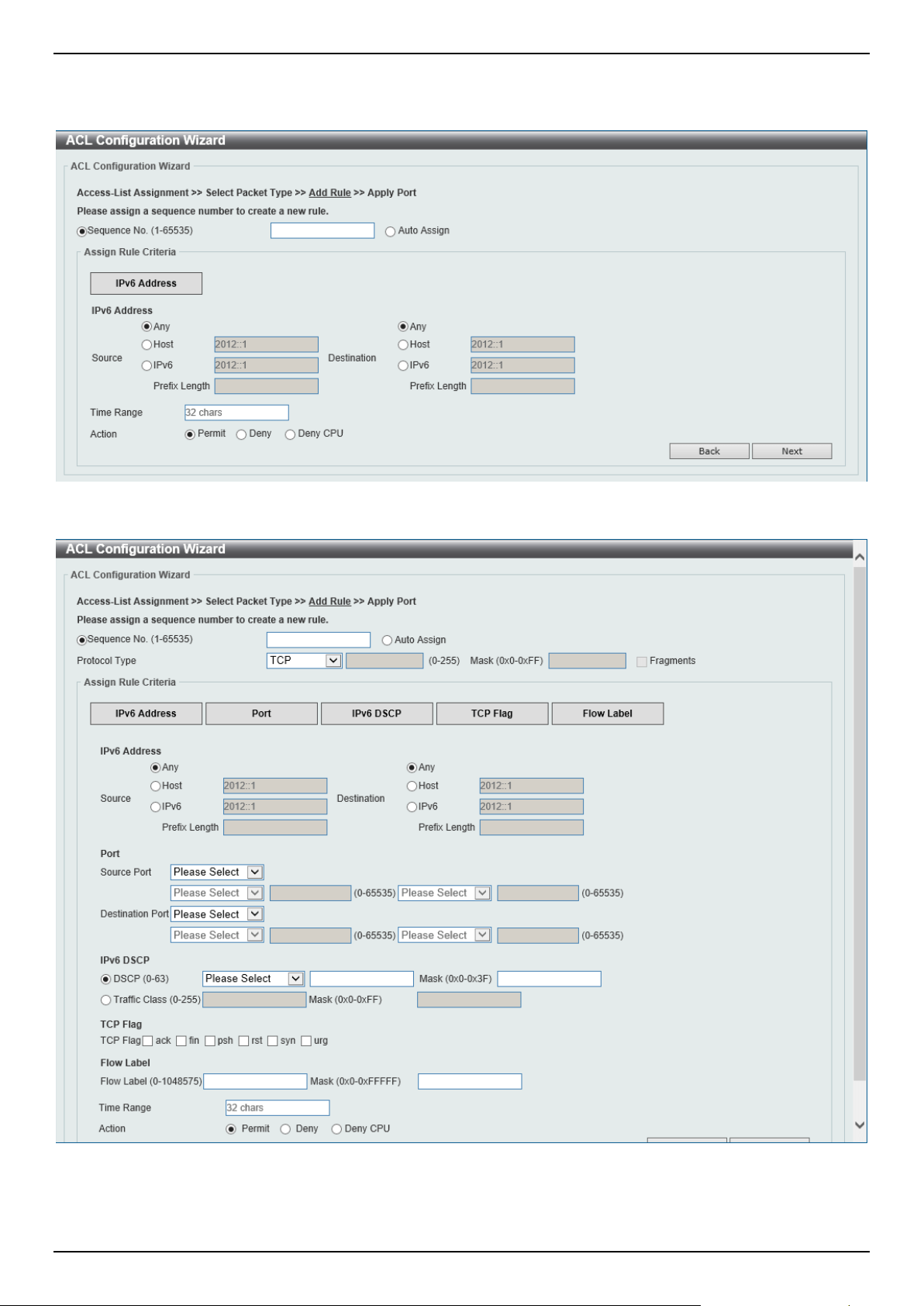
DGS-1520 Series Gigabit Ethernet Smart Managed Switch Web UI Reference Guide
375
Extended/Standard IPv6 ACL
Selecting to Create or Update an IPv6 ACL and click the Next button to view the following window:
Figure 8-7 ACL Configuration Wizard (Standard IPv6 ACL) Window
Figure 8-8 ACL Configuration Wizard (Extended IPv6 ACL) Window

DGS-1520 Series Gigabit Ethernet Smart Managed Switch Web UI Reference Guide
376
The fields that can be configured are described below:
Parameter Description
Sequence No.
Enter the ACL rule number here. This value must be between 1 and 65535. Select
Auto Assign to automatically generate an ACL rule number for this entry.
Protocol Type Select the protocol type option here. Options to choose from are TCP, UDP, ICMP,
Protocol ID, ESP (50), PCP (108), SCTP (132), and None.
• Value - The protocol ID can also manually be entered here. The range is
from 0 to 255.
• Mask - After selecting the Protocol ID option, manually enter the protocol
mask value here. The range is from 0x0 to 0xFF.
• Fragments - Select this option to include packet fragment filtering.
The fields that can be configured in Assign rule criteria are described below:
Parameter Description
Source
Select and enter the source information here. Options to choose from are:
• Any - Any source traffic will be evaluated according to the conditions of this
rule.
• Host - Enter the source host IPv6 address here.
• IPv6 - The Prefix Length option will be available. Enter the source IPv6
address and prefix length value in the spaces provided.
Destination
Select and enter the destination information here. Options to choose from are:
• Any - Any destination traffic will be evaluated according to the conditions of
this rule.
• Host - Enter the destination host IPv6 address here.
• IPv6 - The Prefix Length option will be available. Enter the destination IPv6
address and prefix length value in the spaces provided.
Source Port
Select and enter the source port value here. Options to choose from are:
• = - The specific selected port number will be used.
• > - All ports greater than the selected port, will be used.
• < - All ports smaller than the selected port, will be used.
• ≠ - All ports, excluding the selected port, will be used.
• Range - The start port number and end port number selected, of the range,
will be used. Alternatively, the port number(s) can manually be entered in
the space(s) provided, if the port number(s) is/are not available in the drop-
down list.
• Mask - The specified source port number and mask will be used. Enter the
source port mask value in the space provided. The range is from 0x0 to
0xFFFF.
This parameter is only available in the protocol type TCP and UDP.
Destination Port
Select and enter the destination port value here. Options to choose from are:
• = - The specific selected port number will be used.
• > - All ports greater than the selected port, will be used.
• < - All ports smaller than the selected port, will be used.
• ≠ - All ports, excluding the selected port, will be used.
• Range - The start port number and end port number selected, of the range,
will be used. Alternatively, the port number(s) can manually be entered in
the space(s) provided, if the port number(s) is/are not available in the drop-
down list.
• Mask - The specified destination port number and mask will be used. Enter
the destination port mask value in the space provided. The range is from
0x0 to 0xFFFF.
This parameter is only available in the protocol type TCP and UDP.

DGS-1520 Series Gigabit Ethernet Smart Managed Switch Web UI Reference Guide
377
Parameter Description
Specify ICMP Message
Type
Select the ICMP message type used here.
This parameter is only available in the protocol type ICMP.
ICMP Message Type When the ICMP Message Type is not selected, enter the ICMP Message Type
numerical value used here.
When the ICMP Message Type is selected, this numerical value will automatically
be entered.
This parameter is only available in the protocol type ICMP.
Message Code When the ICMP Message Type is not selected, enter the Message Code
numerical value used here.
When the ICMP Message Type is selected, this numerical value will automatically
be entered.
This parameter is only available in the protocol type ICMP.
DSCP Select the DSCP value that will be used here. Options to choose from are default
(0), af11 (10), af12 (12), af13 (14), af21 (18), af22 (20), af23 (22), af31 (26), af32
(28), af33 (30), af41 (34), af42 (36), af43 (38), cs1 (8), cs2 (16), cs3 (24), cs4
(32), cs5 (40), cs6 (48), cs7 (56), and ef (46).
• Value - The DSCP value can also manually be entered here. The range is
from 0 to 63.
• Mask - Enter the DSCP mask value here. The range is from 0x0 to 0x3F.
Traffic Class
Select and enter the traffic class value here. The range is from 0 to 255.
• Mask - Enter the traffic class mask value here. The range is from 0x0 to
0xFF.
TCP Flag
Tick the appropriate TCP flag option to include the flag in this rule. Options to
choose from are ack, fin, psh, rst, syn, and urg.
This parameter is only available in the protocol type TCP.
Flow Label
Enter the flow label value here. This value must be between 0 and 1048575.
• Mask - Enter the flow label mask value here. The range is from 0x0 to
0xFFFFF.
Time Range
Enter the name of the time range profile that will be used in this ACL rule here.
This name can be up to 32 characters long.
Action Select the action that this rule will take here. Options to choose from are Permit,
Deny, and Deny CPU.
Click the Back button to return to the previous step.
Click the Next button to continue to the next step.
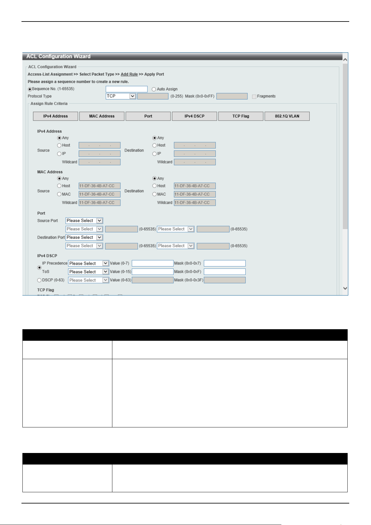
DGS-1520 Series Gigabit Ethernet Smart Managed Switch Web UI Reference Guide
378
Extended Expert ACL
Selecting to Update an extended expert ACL and click the Next button to view the following window:
Figure 8-9 ACL Configuration Wizard (Extended Expert ACL) Window
The fields that can be configured are described below:
Parameter Description
Sequence No.
Enter the ACL rule number here. This value must be between 1 and 65535. Select
Auto Assign to automatically generate an ACL rule number for this entry.
Protocol Type Select the protocol type option here. Options to choose from are TCP, UDP, ICMP,
EIGRP (88), ESP (50), GRE (47), IGMP (2), OSPF (89), PIM (103), VRRP (112),
IP-in-IP (94), PCP (108), Protocol ID, and None.
• Value - The protocol ID can also manually be entered here. The range is
from 0 to 255.
• Mask - After selecting the Protocol ID option, manually enter the protocol
mask value here. The range is from 0x0 to 0xFF.
• Fragments - Select this option to include packet fragment filtering.
The fields that can be configured in Assign rule criteria are described below:
Parameter Description
Source IPv4 Address
Select and enter the source information here. Options to choose from are:
• Any - Any source traffic will be evaluated according to the conditions of this
rule.

DGS-1520 Series Gigabit Ethernet Smart Managed Switch Web UI Reference Guide
379
Parameter Description
• Host - Enter the source host IP address here.
• IP - The Wildcard option will be available. Enter the group of source IP
addresses by using a wildcard bitmap. The bit corresponding to the bit value
1 will be ignored. The bit corresponding to the bit value 0 will be checked.
Destination IPv4 Address
Select and enter the destination information here. Options to choose from are:
• Any - Any destination traffic will be evaluated according to the conditions of
this rule.
• Host - Enter the destination host IP address here.
• IP - The Wildcard option will be available. Enter the group of destination IP
addresses by using a wildcard bitmap. The bit corresponding to the bit value
1 will be ignored. The bit corresponding to the bit value 0 will be checked.
Source MAC Address
Select and enter the source MAC address information here. Options to choose
from are:
• Any - Any source traffic will be evaluated according to the conditions of this
rule.
• Host - Enter the source host MAC address here.
• MAC - The Wildcard option will be available. Enter the source MAC
address and wildcard value in the spaces provided.
Destination MAC Address
Select and enter the destination MAC address information here. Options to choose
from are:
• Any - Any destination traffic will be evaluated according to the conditions of
this rule.
• Host - Enter the destination host MAC address here.
• MAC - The Wildcard option will be available. Enter the destination MAC
address and wildcard value in the spaces provided.
Source Port
Select and enter the source port value here. Options to choose from are:
• = - The specific selected port number will be used.
• > - All ports greater than the selected port, will be used.
• < - All ports smaller than the selected port, will be used.
• ≠ - All ports, excluding the selected port, will be used.
• Range - The start port number and end port number selected, of the range,
will be used. Alternatively, the port number(s) can manually be entered in
the space(s) provided, if the port number(s) is/are not available in the drop-
down list.
• Mask - The specified source port number and mask will be used. Enter the
source port mask value in the space provided. The range is from 0x0 to
0xFFFF.
This parameter is only available in the protocol type TCP and UDP.
Destination Port
Select and enter the destination port value here. Options to choose from are:
• = - The specific selected port number will be used.
• > - All ports greater than the selected port, will be used.
• < - All ports smaller than the selected port, will be used.
• ≠ - All ports, excluding the selected port, will be used.
• Range - The start port number and end port number selected, of the range,
will be used. Alternatively, the port number(s) can manually be entered in
the space(s) provided, if the port number(s) is/are not available in the drop-
down list.
• Mask - The specified destination port number and mask will be used. Enter
the destination port mask value in the space provided. The range is from
0x0 to 0xFFFF.
This parameter is only available in the protocol type TCP and UDP.
Specify ICMP Message
Type
Select the ICMP message type used here.

DGS-1520 Series Gigabit Ethernet Smart Managed Switch Web UI Reference Guide
380
Parameter Description
This parameter is only available in the protocol type ICMP.
ICMP Message Type When the ICMP Message Type is not selected, enter the ICMP Message Type
numerical value used here. The range is from 0 to 255.
When the ICMP Message Type is selected, this numerical value will automatically
be entered.
This parameter is only available in the protocol type ICMP.
Message Code When the ICMP Message Type is not selected, enter the Message Code
numerical value used here. The range is from 0 to 255.
When the ICMP Message Type is selected, this numerical value will automatically
be entered.
This parameter is only available in the protocol type ICMP.
IP Precedence Select the IP precedence value used here. Options to choose from are routine (0),
priority (1), immediate (2), flash (3), flash-override (4), critical (5), internet (6),
and network (7).
• Value - The IP precedence value can also manually be entered here. The
range is from 0 to 7.
• Mask - Enter the IP precedence mask value here. The range is from 0x0 to
0x7.
ToS Select the Type-of-Service (ToS) value that will be used here. Options to choose
from are normal (0), min-monetary-cost (1), max-reliability (2), max-
throughput (4), and min-delay (8).
• Value - The ToS value can also manually be entered here. The range is
from 0 to 15.
• Mask - Enter the ToS mask value here. The range is from 0x0 to 0xF.
DSCP Select the DSCP value that will be used here. Options to choose from are default
(0), af11 (10), af12 (12), af13 (14), af21 (18), af22 (20), af23 (22), af31 (26), af32
(28), af33 (30), af41 (34), af42 (36), af43 (38), cs1 (8), cs2 (16), cs3 (24), cs4
(32), cs5 (40), cs6 (48), cs7 (56), and ef (46).
• Value - The DSCP value can also manually be entered here. The range is
from 0 to 63.
• Mask - Enter the DSCP mask value here. The range is from 0x0 to 0x3F.
TCP Flag
Tick the appropriate TCP flag option to include the flag in this rule. Options to
choose from are ack, fin, psh, rst, syn, and urg.
This parameter is only available in the protocol type TCP.
CoS Select the CoS value that will be used here. The range is from 0 to 7.
• Mask - Enter the CoS mask value here. The range is from 0x0 to 0x7.
Inner CoS
After selecting the CoS value, select the inner CoS value that will be used here.
The range is from 0 to 7.
• Mask - Enter the inner CoS mask value here. The range is from 0x0 to 0x7.
VID
Enter the VLAN ID that will be associated with this ACL rule here. The range is
from 1 to 4094.
• Mask - Enter the VLAN ID mask value here. The range is from 0x0 to
0xFFF.
Inner VID
Enter the inner VLAN ID that will be associated with this ACL rule here. The range
is from 1 to 4094.
• Mask - Enter the inner VLAN ID mask value here. The range is from 0x0 to
0xFFF.
VLAN Range
Select and enter the VLAN range that will be associated with this ACL rule here.
Enter the starting and ending VLANs in the spaces provided. The range is from 1
to 4094.
Time Range
Enter the name of the time range profile that will be used in this ACL rule here.
This name can be up to 32 characters long.
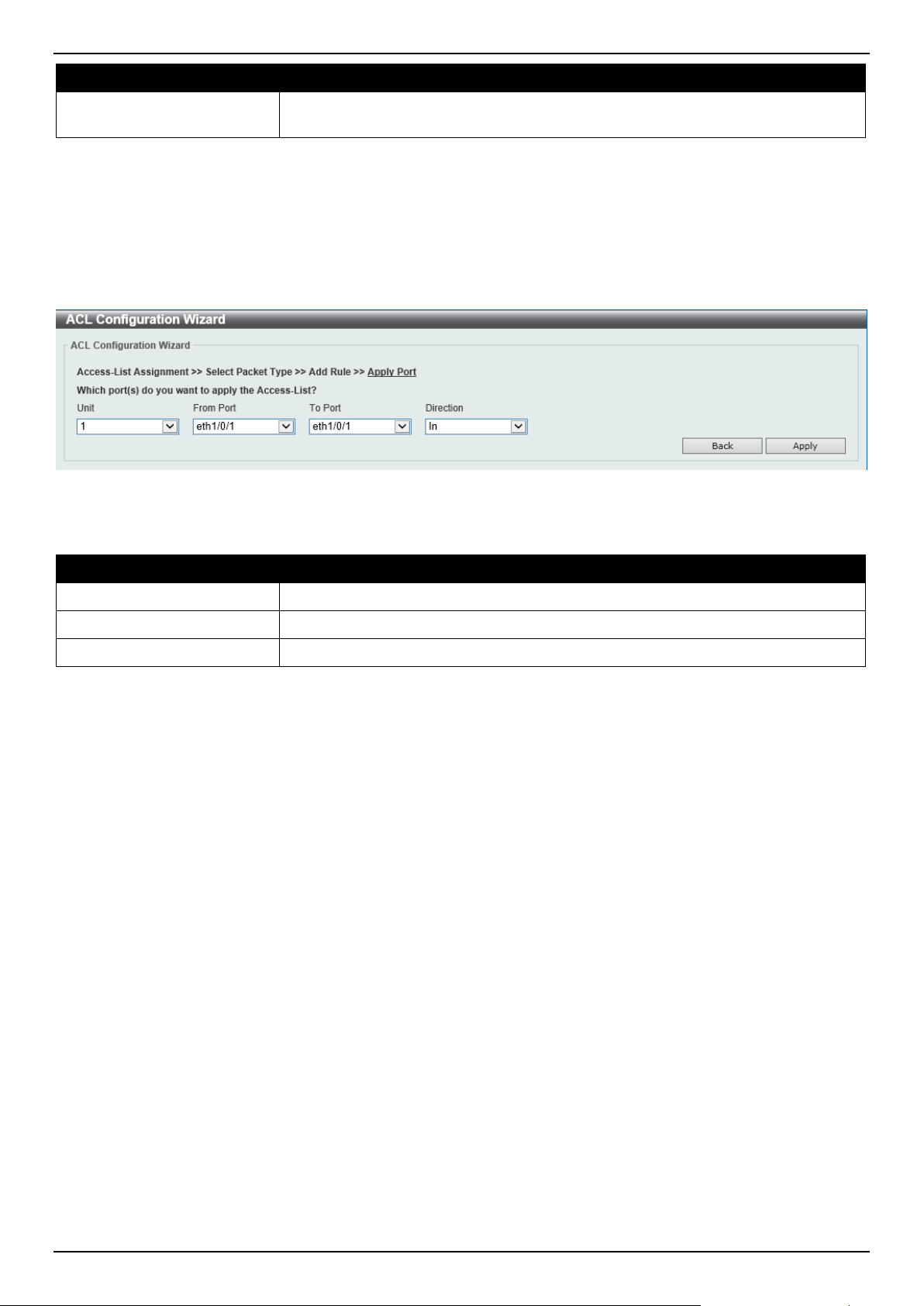
DGS-1520 Series Gigabit Ethernet Smart Managed Switch Web UI Reference Guide
381
Parameter Description
Action Select the action that this rule will take here. Options to choose from are Permit,
Deny, and Deny CPU.
Click the Back button to return to the previous step.
Click the Next button to continue to the next step.
Step 4 - Apply Port
After clicking the Next button, the following window will appear.
Figure 8-10 ACL Configuration Wizard (Create, Port) Window
The fields that can be configured are described below:
Parameter Description
Unit
Select the Switch unit that will be used for this configuration here.
From Port - To Port
Select the appropriate port range used for the configuration here.
Direction Select the direction here. Options to choose from are In and Out.
Click the Back button to return to the previous step.
Click the Apply button to accept the changes made and return to the main ACL Wizard window.
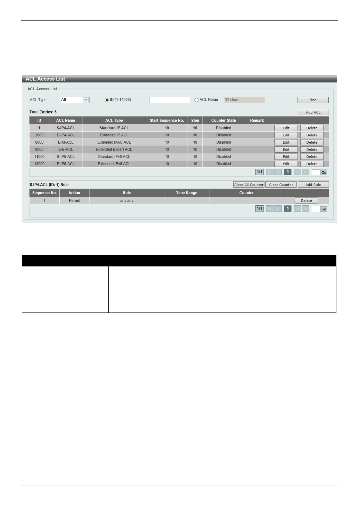
DGS-1520 Series Gigabit Ethernet Smart Managed Switch Web UI Reference Guide
382
ACL Access List
This window is used to display and configure the ACLs, ACL rules, and settings.
To view the following window, click ACL > ACL Access List, as shown below:
Figure 8-11 ACL Access List Window
The fields that can be configured are described below:
Parameter Description
ACL Type Select the ACL type to find here. Options to choose from are All, IP ACL, IPv6
ACL, MAC ACL, and Expert ACL.
ID
Select and enter the access list ID here. The range is from 1 to 14999.
ACL Name
Select and enter the access list name here. This name can be up to 32 characters
long.
Click the Find button to locate a specific entry based on the information entered.
Click the Add ACL button to create a new ACL.
Click the Edit button to re-configure the specific ACL.
Click the Delete button, next to the ACL, to remove the specific ACL.
Enter a page number and click the Go button to navigate to a specific page when multiple pages exist.
Click the Clear All Counter button to clear all the counter information displayed.
Click the Clear Counter button to clear the counter information for the rule displayed.
Click the Add Rule button to create an ACL rule for the ACL selected.
Click the Delete button, next to the ACL rule, to remove the specific ACL rule.
Enter a page number and click the Go button to navigate to a specific page when multiple pages exist.
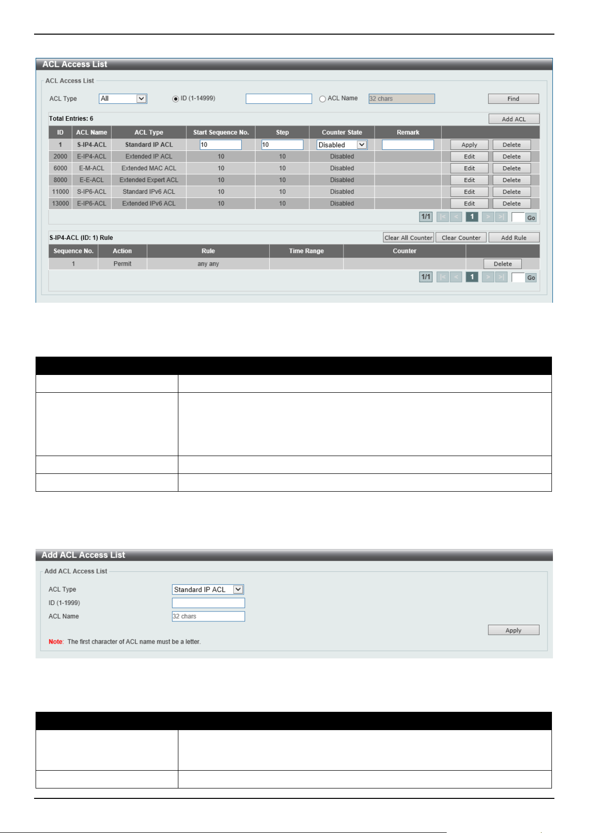
DGS-1520 Series Gigabit Ethernet Smart Managed Switch Web UI Reference Guide
383
After clicking the Edit button, the following page will appear.
Figure 8-12 ACL Access List (Edit) Window
After clicking the Edit button, the fields that can be configured are described below:
Parameter Description
Start Sequence No.
Enter the start sequence number here.
Step
Enter the sequence number step here. The step range is from 1 to 32. This
specifies the number that the sequence numbers step. For example, if the
increment (step) value is 5 and the beginning sequence number is 20, the
subsequent sequence numbers are 25, 30, 35, 40, and so on. By default, this
value is 10.
Counter State
Select to enable or disable the counter state option here.
Remark
Enter an optional remark that will be associated with this ACL here.
Click the Apply button to accept the changes made.
After clicking the Add ACL button, the following page will appear.
Figure 8-13 ACL Access List (Add ACL) Window
After clicking the Add ACL button, the fields that can be configured are described below:
Parameter Description
ACL Type
Select the ACL type that will be created here. Options to choose from are
Standard IP ACL, Extended IP ACL, Standard IPv6 ACL, Extended IPv6 ACL,
Extended MAC ACL, and Extended Expert ACL.
ID
Enter the ID for the ACL here.
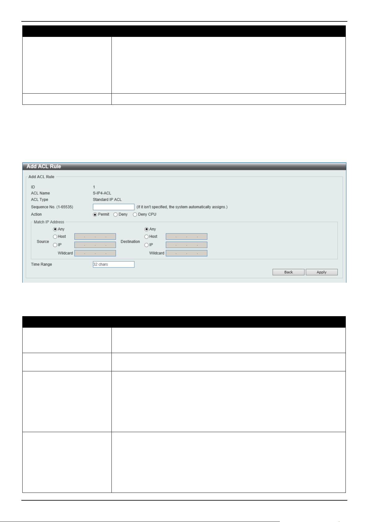
DGS-1520 Series Gigabit Ethernet Smart Managed Switch Web UI Reference Guide
384
Parameter Description
• For a Standard IP ACL, the range from 1 to 1999.
• For an Extended IP ACL, the range from 2000 to 3999.
• For a Standard IPv6 ACL, the range from 11000 to 12999.
• For an Extended IPv6 ACL, the range from 13000 to 14999.
• For an Extended MAC ACL, the range from 6000 to 7999.
• For an Extended Expert ACL, the range from 8000 to 9999.
ACL Name
Enter the name of the ACL here. This name can be up to 32 characters long.
Click the Apply button to accept the changes made.
Standard IP ACL
After selecting a Standard IP ACL and clicking the Add Rule button, the following page will appear.
Figure 8-14 Standard IP ACL (Add Rule) Window
The fields that can be configured are described below:
Parameter Description
Sequence No.
Enter the sequence number of this ACL rule here. The range is from 1 to 65535. If
this value is not specified, the system will automatically generate an ACL rule
number for this entry.
Action Select the action that this rule will take here. Options to choose from are Permit,
Deny, and Deny CPU.
Source
Select and enter the source information here. Options to choose from are:
• Any - Any source traffic will be evaluated according to the conditions of this
rule.
• Host - Enter the source host IP address here.
• IP - The Wildcard option will be available. Enter the group of source IP
addresses by using a wildcard bitmap. The bit corresponding to the bit value
1 will be ignored. The bit corresponding to the bit value 0 will be checked.
Destination
Select and enter the destination information here. Options to choose from are:
• Any - Any destination traffic will be evaluated according to the conditions of
this rule.
• Host - Enter the destination host IP address here.
• IP - The Wildcard option will be available. Enter the group of destination IP
addresses by using a wildcard bitmap. The bit corresponding to the bit value
1 will be ignored. The bit corresponding to the bit value 0 will be checked.
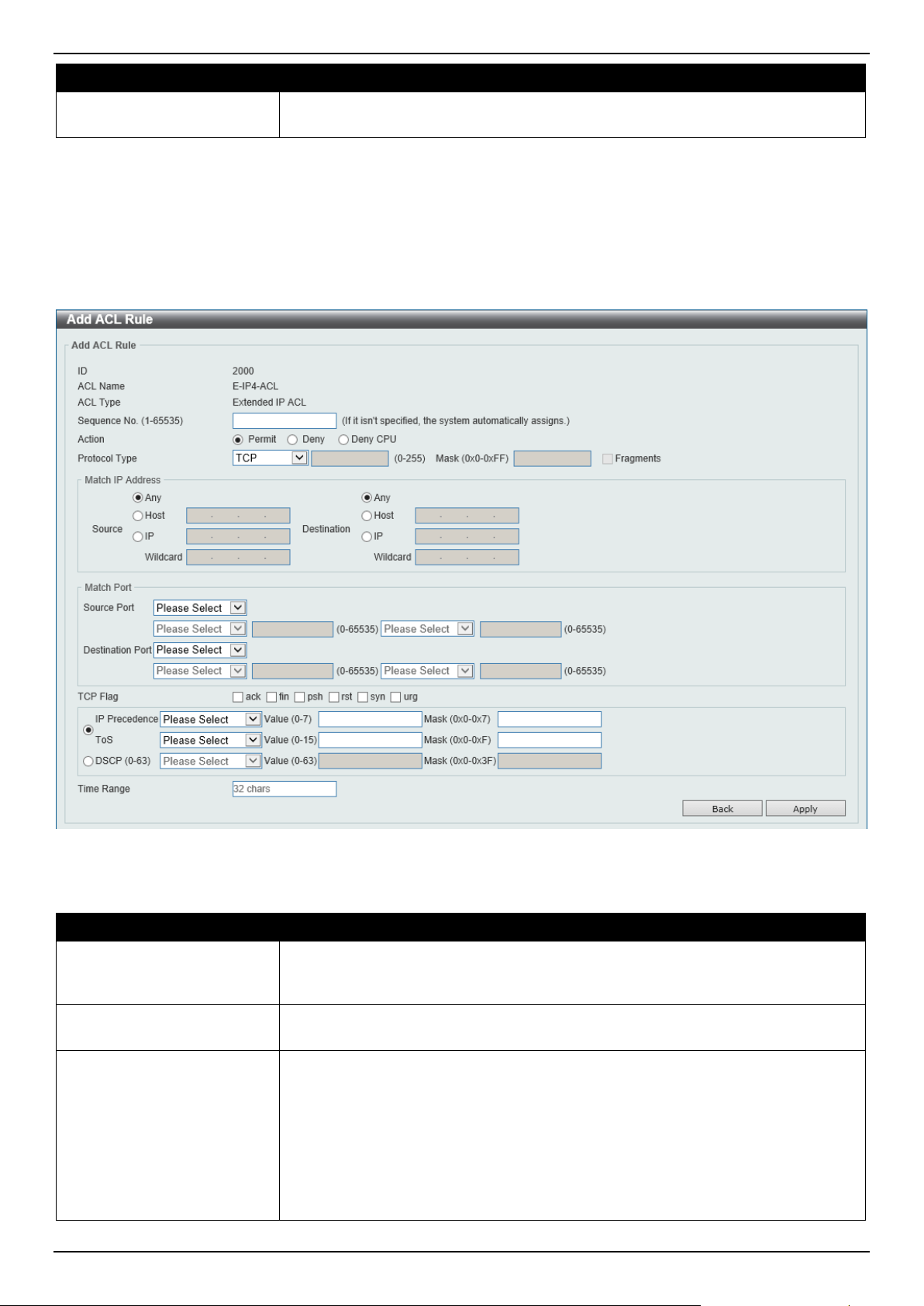
DGS-1520 Series Gigabit Ethernet Smart Managed Switch Web UI Reference Guide
385
Parameter Description
Time Range
Enter the name of the time range profile that will be used in this ACL rule here.
This name can be up to 32 characters long.
Click the Apply button to accept the changes made.
Click the Back button to discard the changes made and return to the previous page.
Extended IP ACL
After selecting an Extended IP ACL and clicking the Add Rule button, the following page will appear.
Figure 8-15 Extended IP ACL (Add Rule) Window
The fields that can be configured are described below:
Parameter Description
Sequence No.
Enter the sequence number of this ACL rule here. The range is from 1 to 65535. If
this value is not specified, the system will automatically generate an ACL rule
number for this entry.
Action Select the action that this rule will take here. Options to choose from are Permit,
Deny, and Deny CPU.
Protocol Type Select the protocol type option here. Options to choose from are TCP, UDP, ICMP,
EIGRP (88), ESP (50), GRE (47), IGMP (2), OSPF (89), PIM (103), VRRP (112),
IP-in-IP (94), PCP (108), Protocol ID, and None.
• Value - The protocol ID can also manually be entered here. The range is
from 0 to 255.
• Mask - After selecting the Protocol ID option, manually enter the protocol
mask value here. The range is from 0x0 to 0xFF.
• Fragments - Select this option to include packet fragment filtering.

DGS-1520 Series Gigabit Ethernet Smart Managed Switch Web UI Reference Guide
386
Parameter Description
Source
Select and enter the source information here. Options to choose from are:
• Any - Any source traffic will be evaluated according to the conditions of this
rule.
• Host - Enter the source host IP address here.
• IP - The Wildcard option will be available. Enter the group of source IP
addresses by using a wildcard bitmap. The bit corresponding to the bit value
1 will be ignored. The bit corresponding to the bit value 0 will be checked.
Destination
Select and enter the destination information here. Options to choose from are:
• Any - Any destination traffic will be evaluated according to the conditions of
this rule.
• Host - Enter the destination host IP address here.
• IP - The Wildcard option will be available. Enter the group of destination IP
addresses by using a wildcard bitmap. The bit corresponding to the bit value
1 will be ignored. The bit corresponding to the bit value 0 will be checked.
Source Port
Select and enter the source port value here. Options to choose from are:
• = - The specific selected port number will be used.
• > - All ports greater than the selected port, will be used.
• < - All ports smaller than the selected port, will be used.
• ≠ - All ports, excluding the selected port, will be used.
• Range - The start port number and end port number selected, of the range,
will be used. Alternatively, the port number(s) can manually be entered in
the space(s) provided, if the port number(s) is/are not available in the drop-
down list.
• Mask - The specified source port number and mask will be used. Enter the
source port mask value in the space provided. The range is from 0x0 to
0xFFFF.
This parameter is only available in the protocol type TCP and UDP.
Destination Port
Select and enter the destination port value here. Options to choose from are:
• = - The specific selected port number will be used.
• > - All ports greater than the selected port, will be used.
• < - All ports smaller than the selected port, will be used.
• ≠ - All ports, excluding the selected port, will be used.
• Range - The start port number and end port number selected, of the range,
will be used. Alternatively, the port number(s) can manually be entered in
the space(s) provided, if the port number(s) is/are not available in the drop-
down list.
• Mask - The specified destination port number and mask will be used. Enter
the destination port mask value in the space provided. The range is from
0x0 to 0xFFFF.
This parameter is only available in the protocol type TCP and UDP.
Specify ICMP Message
Type
Select the ICMP message type used here.
This parameter is only available in the protocol type ICMP.
ICMP Message Type When the ICMP Message Type is not selected, enter the ICMP Message Type
numerical value used here. The range is from 0 to 255.
When the ICMP Message Type is selected, this numerical value will automatically
be entered.
This parameter is only available in the protocol type ICMP.
Message Code When the ICMP Message Type is not selected, enter the Message Code
numerical value used here. The range is from 0 to 255.
When the ICMP Message Type is selected, this numerical value will automatically
be entered.
This parameter is only available in the protocol type ICMP.
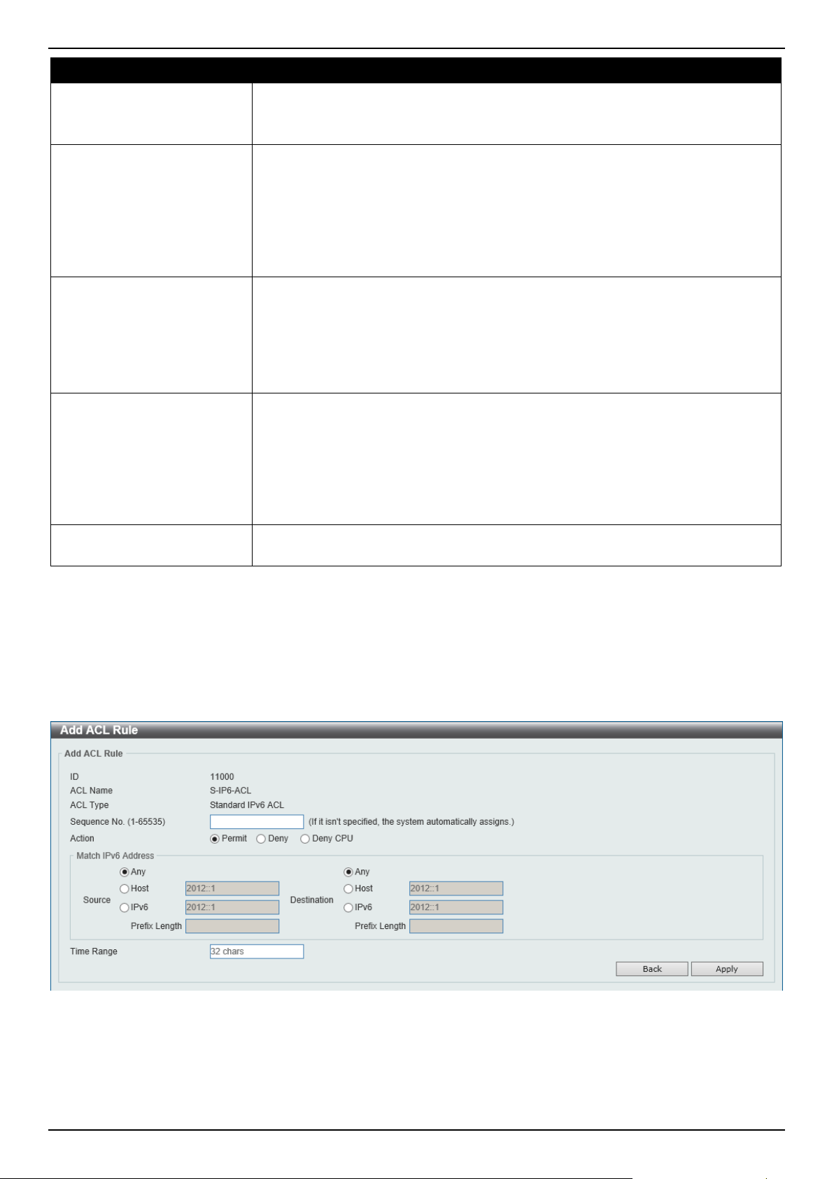
DGS-1520 Series Gigabit Ethernet Smart Managed Switch Web UI Reference Guide
387
Parameter Description
TCP Flag
Tick the appropriate TCP flag option to include the flag in this rule. Options to
choose from are ack, fin, psh, rst, syn, and urg.
This parameter is only available in the protocol type TCP.
IP Precedence Select the IP precedence value used here. Options to choose from are routine (0),
priority (1), immediate (2), flash (3), flash-override (4), critical (5), internet (6),
and network (7).
• Value - The IP precedence value can also manually be entered here. The
range is from 0 to 7.
• Mask - Enter the IP precedence mask value here. The range is from 0x0 to
0x7.
ToS Select the Type-of-Service (ToS) value that will be used here. Options to choose
from are normal (0), min-monetary-cost (1), max-reliability (2), max-
throughput (4), and min-delay (8).
• Value - The ToS value can also manually be entered here. The range is
from 0 to 15.
• Mask - Enter the ToS mask value here. The range is from 0x0 to 0xF.
DSCP Select the DSCP value that will be used here. Options to choose from are default
(0), af11 (10), af12 (12), af13 (14), af21 (18), af22 (20), af23 (22), af31 (26), af32
(28), af33 (30), af41 (34), af42 (36), af43 (38), cs1 (8), cs2 (16), cs3 (24), cs4
(32), cs5 (40), cs6 (48), cs7 (56), and ef (46).
• Value - The DSCP value can also manually be entered here. The range is
from 0 to 63.
• Mask - Enter the DSCP mask value here. The range is from 0x0 to 0x3F.
Time Range
Enter the name of the time range profile that will be used in this ACL rule here.
This name can be up to 32 characters long.
Click the Apply button to accept the changes made.
Click the Back button to discard the changes made and return to the previous page.
Standard IPv6 ACL
After selecting a Standard IPv6 ACL and clicking the Add Rule button, the following page will appear.
Figure 8-16 Standard IPv6 ACL (Add Rule) Window

DGS-1520 Series Gigabit Ethernet Smart Managed Switch Web UI Reference Guide
388
The fields that can be configured are described below:
Parameter Description
Sequence No.
Enter the sequence number of this ACL rule here. The range is from 1 to 65535. If
this value is not specified, the system will automatically generate an ACL rule
number for this entry.
Action Select the action that this rule will take here. Options to choose from are Permit,
Deny, and Deny CPU.
Source
Select and enter the source information here. Options to choose from are:
• Any - Any source traffic will be evaluated according to the conditions of this
rule.
• Host - Enter the source host IPv6 address here.
• IPv6 - The Prefix Length option will be available. Enter the source IPv6
address and prefix length value in the spaces provided.
Destination
Select and enter the destination information here. Options to choose from are:
• Any - Any destination traffic will be evaluated according to the conditions of
this rule.
• Host - Enter the destination host IPv6 address here.
• IPv6 - The Prefix Length option will be available. Enter the destination IPv6
address and prefix length value in the spaces provided.
Time Range
Enter the name of the time range profile that will be used in this ACL rule here.
This name can be up to 32 characters long.
Click the Apply button to accept the changes made.
Click the Back button to discard the changes made and return to the previous page.
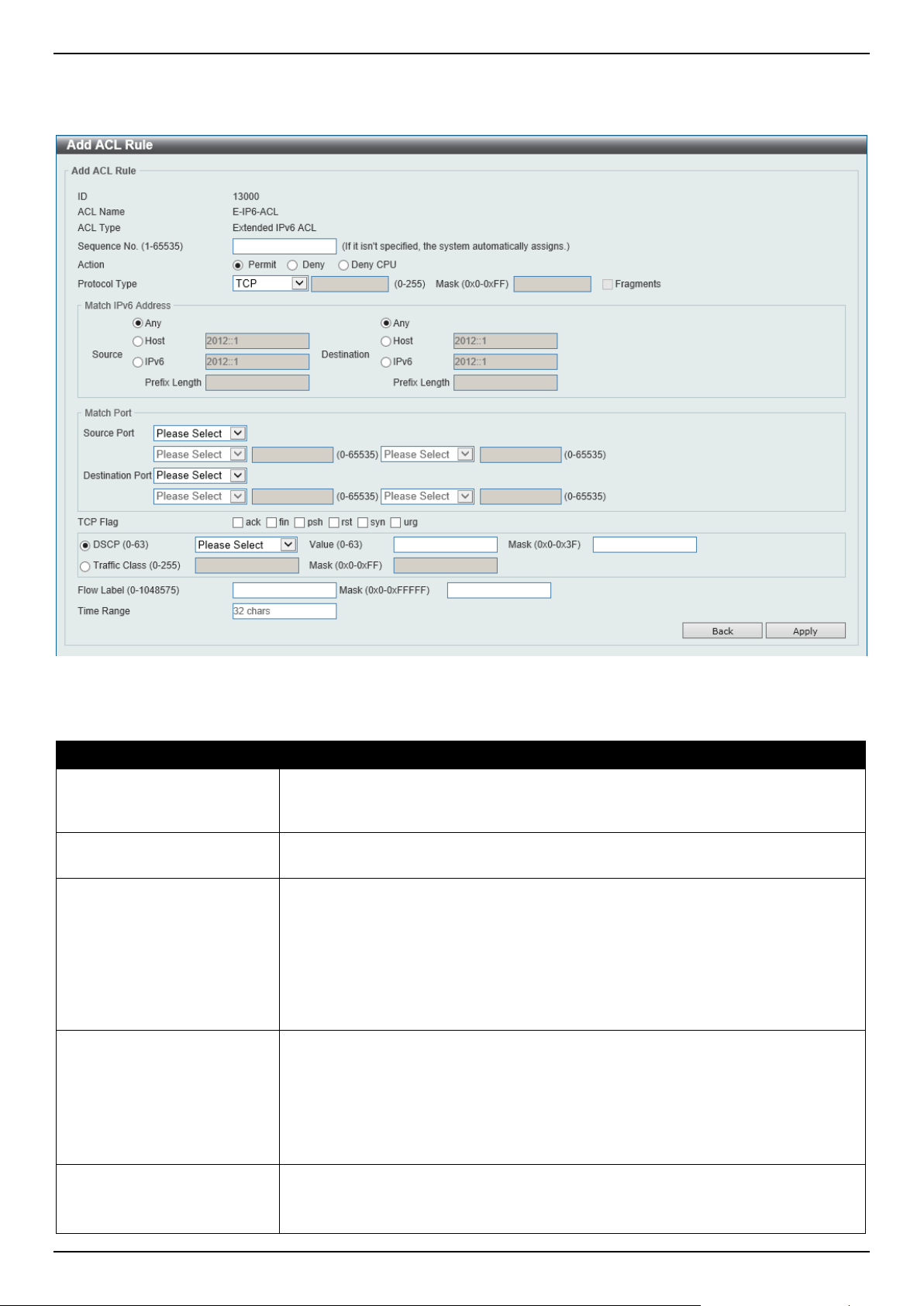
DGS-1520 Series Gigabit Ethernet Smart Managed Switch Web UI Reference Guide
389
Extended IPv6 ACL
After selecting an Extended IPv6 ACL and clicking the Add Rule button, the following page will appear.
Figure 8-17 Extended IPv6 ACL (Add Rule) Window
The fields that can be configured are described below:
Parameter Description
Sequence No.
Enter the sequence number of this ACL rule here. The range is from 1 to 65535. If
this value is not specified, the system will automatically generate an ACL rule
number for this entry.
Action Select the action that this rule will take here. Options to choose from are Permit,
Deny, and Deny CPU.
Protocol Type Select the protocol type option here. Options to choose from are TCP, UDP, ICMP,
Protocol ID, ESP (50), PCP (108), SCTP (132), and None.
• Value - The protocol ID can also manually be entered here. The range is
from 0 to 255.
• Mask - After selecting the Protocol ID option, manually enter the protocol
mask value here. The range is from 0x0 to 0xFF.
• Fragments - Select this option to include packet fragment filtering.
Source
Select and enter the source information here. Options to choose from are:
• Any - Any source traffic will be evaluated according to the conditions of this
rule.
• Host - Enter the source host IPv6 address here.
• IPv6 - The Prefix Length option will be available. Enter the source IPv6
address and prefix length value in the spaces provided.
Destination
Select and enter the destination information here. Options to choose from are:
• Any - Any destination traffic will be evaluated according to the conditions of
this rule.

DGS-1520 Series Gigabit Ethernet Smart Managed Switch Web UI Reference Guide
390
Parameter Description
• Host - Enter the destination host IPv6 address here.
• IPv6 - The Prefix Length option will be available. Enter the destination IPv6
address and prefix length value in the spaces provided.
Source Port
Select and enter the source port value here. Options to choose from are:
• = - The specific selected port number will be used.
• > - All ports greater than the selected port, will be used.
• < - All ports smaller than the selected port, will be used.
• ≠ - All ports, excluding the selected port, will be used.
• Range - The start port number and end port number selected, of the range,
will be used. Alternatively, the port number(s) can manually be entered in
the space(s) provided, if the port number(s) is/are not available in the drop-
down list.
• Mask - The specified source port number and mask will be used. Enter the
source port mask value in the space provided. The range is from 0x0 to
0xFFFF.
This parameter is only available in the protocol type TCP and UDP.
Destination Port
Select and enter the destination port value here. Options to choose from are:
• = - The specific selected port number will be used.
• > - All ports greater than the selected port, will be used.
• < - All ports smaller than the selected port, will be used.
• ≠ - All ports, excluding the selected port, will be used.
• Range - The start port number and end port number selected, of the range,
will be used. Alternatively, the port number(s) can manually be entered in
the space(s) provided, if the port number(s) is/are not available in the drop-
down list.
• Mask - The specified destination port number and mask will be used. Enter
the destination port mask value in the space provided. The range is from
0x0 to 0xFFFF.
This parameter is only available in the protocol type TCP and UDP.
TCP Flag
Tick the appropriate TCP flag option to include the flag in this rule. Options to
choose from are ack, fin, psh, rst, syn, and urg.
This parameter is only available in the protocol type TCP.
Specify ICMP Message
Type
Select the ICMP message type used here.
This parameter is only available in the protocol type ICMP.
ICMP Message Type When the ICMP Message Type is not selected, enter the ICMP Message Type
numerical value used here.
When the ICMP Message Type is selected, this numerical value will automatically
be entered.
This parameter is only available in the protocol type ICMP.
Message Code When the ICMP Message Type is not selected, enter the Message Code
numerical value used here.
When the ICMP Message Type is selected, this numerical value will automatically
be entered.
This parameter is only available in the protocol type ICMP.
DSCP Select the DSCP value that will be used here. Options to choose from are default
(0), af11 (10), af12 (12), af13 (14), af21 (18), af22 (20), af23 (22), af31 (26), af32
(28), af33 (30), af41 (34), af42 (36), af43 (38), cs1 (8), cs2 (16), cs3 (24), cs4
(32), cs5 (40), cs6 (48), cs7 (56), and ef (46).
• Value - The DSCP value can also manually be entered here. The range is
from 0 to 63.
• Mask - Enter the DSCP mask value here. The range is from 0x0 to 0x3F.
Traffic Class
Select and enter the traffic class value here. The range is from 0 to 255.
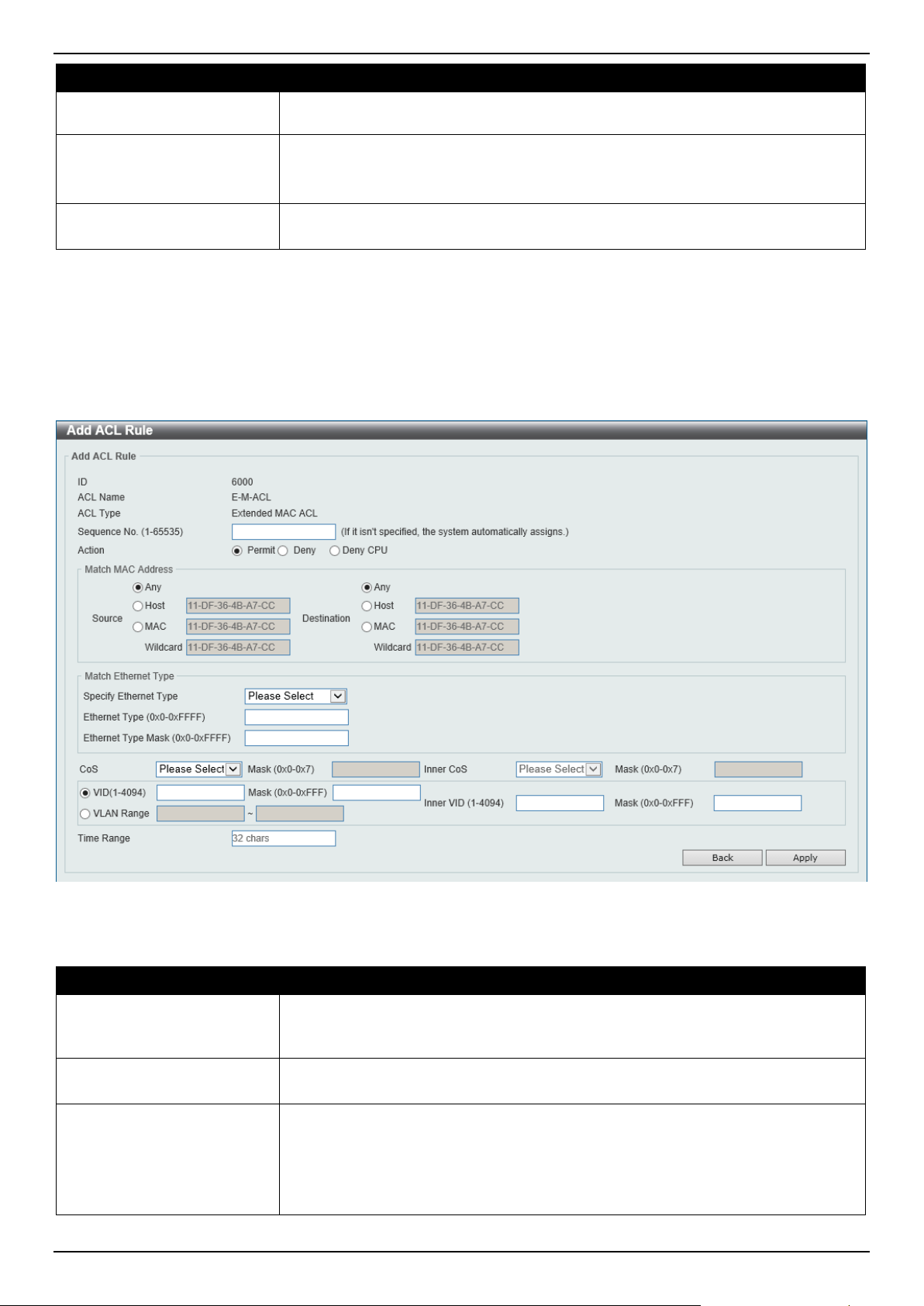
DGS-1520 Series Gigabit Ethernet Smart Managed Switch Web UI Reference Guide
391
Parameter Description
• Mask - Enter the traffic class mask value here. The range is from 0x0 to
0xFF.
Flow Label
Enter the flow label value here. This value must be between 0 and 1048575.
• Mask - Enter the flow label mask value here. The range is from 0x0 to
0xFFFFF.
Time Range
Enter the name of the time range profile that will be used in this ACL rule here.
This name can be up to 32 characters long.
Click the Apply button to accept the changes made.
Click the Back button to discard the changes made and return to the previous page.
Extended MAC ACL
After selecting an Extended MAC ACL and clicking the Add Rule button, the following page will appear.
Figure 8-18 Extended MAC ACL (Add Rule) Window
The fields that can be configured are described below:
Parameter Description
Sequence No.
Enter the sequence number of this ACL rule here. The range is from 1 to 65535. If
this value is not specified, the system will automatically generate an ACL rule
number for this entry.
Action Select the action that this rule will take here. Options to choose from are Permit,
Deny, and Deny CPU.
Source
Select and enter the source MAC address information here. Options to choose
from are:
• Any - Any source traffic will be evaluated according to the conditions of this
rule.
• Host - Enter the source host MAC address here.

DGS-1520 Series Gigabit Ethernet Smart Managed Switch Web UI Reference Guide
392
Parameter Description
• MAC - The Wildcard option will be available. Enter the source MAC
address and wildcard value in the spaces provided.
Destination
Select and enter the destination MAC address information here. Options to choose
from are:
• Any - Any destination traffic will be evaluated according to the conditions of
this rule.
• Host - Enter the destination host MAC address here.
• MAC - The Wildcard option will be available. Enter the destination MAC
address and wildcard value in the spaces provided.
Specify Ethernet Type Select the Ethernet type option here. Options to choose from are aarp, appletalk,
decent-iv, etype-6000, etype-8042, lat, lavc-sca, mop-console, mop-dump,
vines-echo, vines-ip, xns-idp, and arp.
Ethernet Type
Enter the Ethernet type hexadecimal value here. This value must be between 0x0
and 0xFFFF. When the Ethernet type profile is selected, above, the appropriate
hexadecimal value will automatically be entered.
Ethernet Type Mask
Enter the Ethernet type mask hexadecimal value here. This value must be
between 0x0 and 0xFFFF. When the Ethernet type profile is selected, above, the
appropriate hexadecimal value will automatically be entered.
CoS Select the CoS value that will be used here. The range is from 0 to 7.
• Mask - Enter the CoS mask value here. The range is from 0x0 to 0x7.
Inner CoS
After selecting the CoS value, select the inner CoS value that will be used here.
The range is from 0 to 7.
• Mask - Enter the inner CoS mask value here. The range is from 0x0 to 0x7.
VID
Enter the VLAN ID that will be associated with this ACL rule here. The range is
from 1 to 4094.
• Mask - Enter the VLAN ID mask value here. The range is from 0x0 to
0xFFF.
Inner VID
Enter the inner VLAN ID that will be associated with this ACL rule here. The range
is from 1 to 4094.
• Mask - Enter the inner VLAN ID mask value here. The range is from 0x0 to
0xFFF.
VLAN Range
Select and enter the VLAN range that will be associated with this ACL rule here.
Enter the starting and ending VLANs in the spaces provided. The range is from 1
to 4094.
Time Range
Enter the name of the time range profile that will be used in this ACL rule here.
This name can be up to 32 characters long.
Click the Apply button to accept the changes made.
Click the Back button to discard the changes made and return to the previous page.
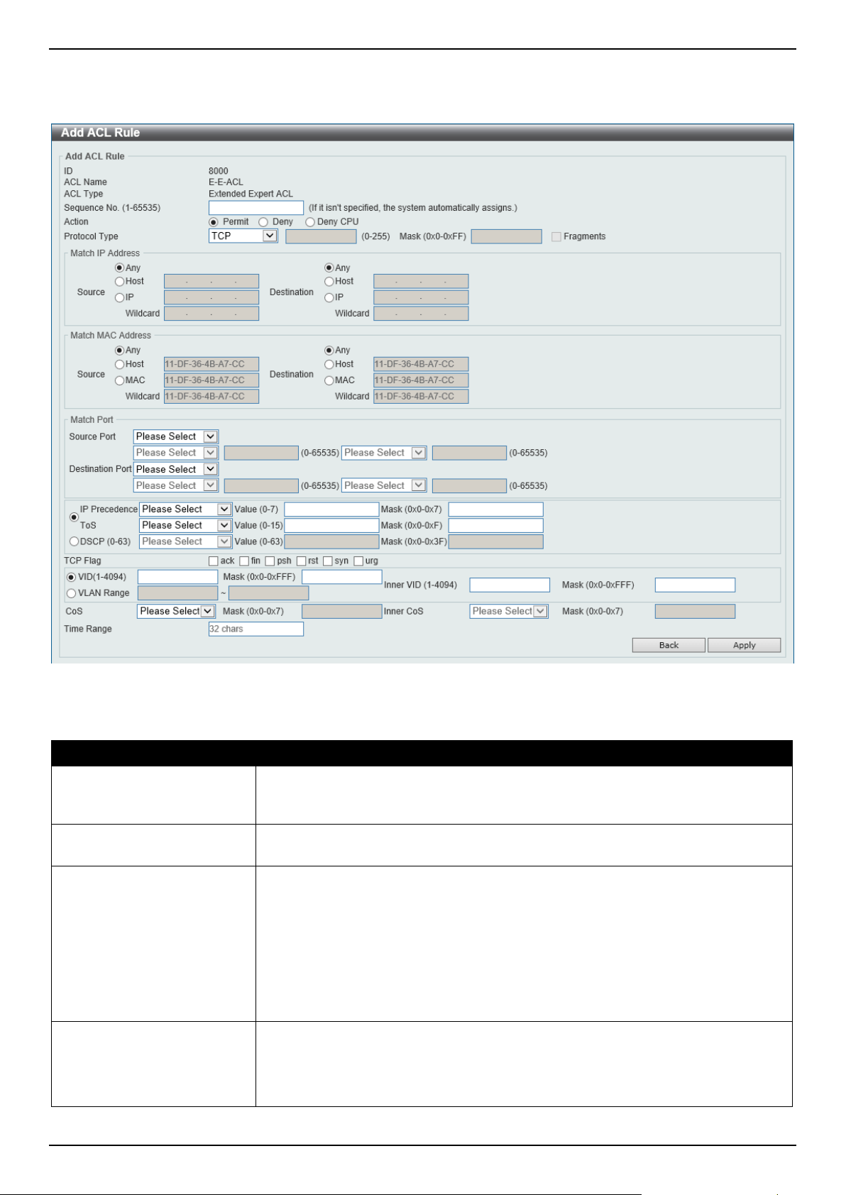
DGS-1520 Series Gigabit Ethernet Smart Managed Switch Web UI Reference Guide
393
Extended Expert ACL
After selecting an Extended Expert ACL and clicking the Add Rule button, the following page will appear.
Figure 8-19 Extended Expert ACL (Add Rule) Window
The fields that can be configured are described below:
Parameter Description
Sequence No.
Enter the sequence number of this ACL rule here. The range is from 1 to 65535. If
this value is not specified, the system will automatically generate an ACL rule
number for this entry.
Action Select the action that this rule will take here. Options to choose from are Permit,
Deny, and Deny CPU.
Protocol Type Select the protocol type option here. Options to choose from are TCP, UDP, ICMP,
EIGRP (88), ESP (50), GRE (47), IGMP (2), OSPF (89), PIM (103), VRRP (112),
IP-in-IP (94), PCP (108), Protocol ID, and None.
• Value - The protocol ID can also manually be entered here. The range is
from 0 to 255.
• Mask - After selecting the Protocol ID option, manually enter the protocol
mask value here. The range is from 0x0 to 0xFF.
• Fragments - Select this option to include packet fragment filtering.
Source IP Address
Select and enter the source information here. Options to choose from are:
• Any - Any source traffic will be evaluated according to the conditions of this
rule.
• Host - Enter the source host IP address here.

DGS-1520 Series Gigabit Ethernet Smart Managed Switch Web UI Reference Guide
394
Parameter Description
• IP - The Wildcard option will be available. Enter the group of source IP
addresses by using a wildcard bitmap. The bit corresponding to the bit value
1 will be ignored. The bit corresponding to the bit value 0 will be checked.
Destination IP Address
Select and enter the destination information here. Options to choose from are:
• Any - Any destination traffic will be evaluated according to the conditions of
this rule.
• Host - Enter the destination host IP address here.
• IP - The Wildcard option will be available. Enter the group of destination IP
addresses by using a wildcard bitmap. The bit corresponding to the bit value
1 will be ignored. The bit corresponding to the bit value 0 will be checked.
Source MAC Address
Select and enter the source MAC address information here. Options to choose
from are:
• Any - Any source traffic will be evaluated according to the conditions of this
rule.
• Host - Enter the source host MAC address here.
• MAC - The Wildcard option will be available. Enter the source MAC
address and wildcard value in the spaces provided.
Destination MAC Address
Select and enter the destination MAC address information here. Options to choose
from are:
• Any - Any destination traffic will be evaluated according to the conditions of
this rule.
• Host - Enter the destination host MAC address here.
• MAC - The Wildcard option will be available. Enter the destination MAC
address and wildcard value in the spaces provided.
Source Port
Select and enter the source port value here. Options to choose from are:
• = - The specific selected port number will be used.
• > - All ports greater than the selected port, will be used.
• < - All ports smaller than the selected port, will be used.
• ≠ - All ports, excluding the selected port, will be used.
• Range - The start port number and end port number selected, of the range,
will be used. Alternatively, the port number(s) can manually be entered in
the space(s) provided, if the port number(s) is/are not available in the drop-
down list.
• Mask - The specified source port number and mask will be used. Enter the
source port mask value in the space provided. The range is from 0x0 to
0xFFFF.
This parameter is only available in the protocol type TCP and UDP.
Destination Port
Select and enter the destination port value here. Options to choose from are:
• = - The specific selected port number will be used.
• > - All ports greater than the selected port, will be used.
• < - All ports smaller than the selected port, will be used.
• ≠ - All ports, excluding the selected port, will be used.
• Range - The start port number and end port number selected, of the range,
will be used. Alternatively, the port number(s) can manually be entered in
the space(s) provided, if the port number(s) is/are not available in the drop-
down list.
• Mask - The specified destination port number and mask will be used. Enter
the destination port mask value in the space provided. The range is from
0x0 to 0xFFFF.
This parameter is only available in the protocol type TCP and UDP.
Specify ICMP Message
Type
Select the ICMP message type used here.
This parameter is only available in the protocol type ICMP.

DGS-1520 Series Gigabit Ethernet Smart Managed Switch Web UI Reference Guide
395
Parameter Description
ICMP Message Type When the ICMP Message Type is not selected, enter the ICMP Message Type
numerical value used here. The range is from 0 to 255.
When the ICMP Message Type is selected, this numerical value will automatically
be entered.
This parameter is only available in the protocol type ICMP.
Message Code When the ICMP Message Type is not selected, enter the Message Code
numerical value used here. The range is from 0 to 255.
When the ICMP Message Type is selected, this numerical value will automatically
be entered.
This parameter is only available in the protocol type ICMP.
IP Precedence Select the IP precedence value used here. Options to choose from are routine (0),
priority (1), immediate (2), flash (3), flash-override (4), critical (5), internet (6),
and network (7).
• Value - The IP precedence value can also manually be entered here. The
range is from 0 to 7.
• Mask - Enter the IP precedence mask value here. The range is from 0x0 to
0x7.
ToS Select the Type-of-Service (ToS) value that will be used here. Options to choose
from are normal (0), min-monetary-cost (1), max-reliability (2), max-
throughput (4), and min-delay (8).
• Value - The ToS value can also manually be entered here. The range is
from 0 to 15.
• Mask - Enter the ToS mask value here. The range is from 0x0 to 0xF.
DSCP Select the DSCP value that will be used here. Options to choose from are default
(0), af11 (10), af12 (12), af13 (14), af21 (18), af22 (20), af23 (22), af31 (26), af32
(28), af33 (30), af41 (34), af42 (36), af43 (38), cs1 (8), cs2 (16), cs3 (24), cs4
(32), cs5 (40), cs6 (48), cs7 (56), and ef (46).
• Value - The DSCP value can also manually be entered here. The range is
from 0 to 63.
• Mask - Enter the DSCP mask value here. The range is from 0x0 to 0x3F.
TCP Flag
Tick the appropriate TCP flag option to include the flag in this rule. Options to
choose from are ack, fin, psh, rst, syn, and urg.
This parameter is only available in the protocol type TCP.
VID
Enter the VLAN ID that will be associated with this ACL rule here. The range is
from 1 to 4094.
• Mask - Enter the VLAN ID mask value here. The range is from 0x0 to
0xFFF.
Inner VID
Enter the inner VLAN ID that will be associated with this ACL rule here. The range
is from 1 to 4094.
• Mask - Enter the inner VLAN ID mask value here. The range is from 0x0 to
0xFFF.
VLAN Range
Select and enter the VLAN range that will be associated with this ACL rule here.
Enter the starting and ending VLANs in the spaces provided. The range is from 1
to 4094.
CoS Select the CoS value that will be used here. The range is from 0 to 7.
• Mask - Enter the CoS mask value here. The range is from 0x0 to 0x7.
Inner CoS
After selecting the CoS value, select the inner CoS value that will be used here.
The range is from 0 to 7.
• Mask - Enter the inner CoS mask value here. The range is from 0x0 to 0x7.
Time Range
Enter the name of the time range profile that will be used in this ACL rule here.
This name can be up to 32 characters long.
Click the Apply button to accept the changes made.
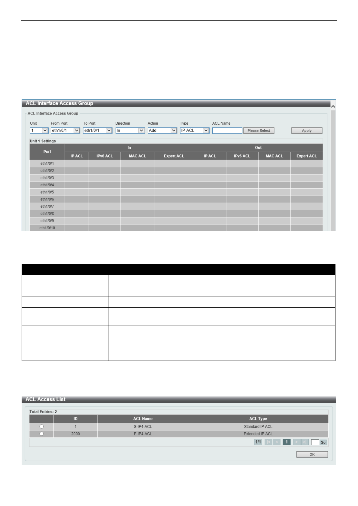
DGS-1520 Series Gigabit Ethernet Smart Managed Switch Web UI Reference Guide
396
Click the Back button to discard the changes made and return to the previous page.
ACL Interface Access Group
This window is used to display and configure the ACL interface access group settings.
To view the following window, click ACL > ACL Interface Access Group, as shown below:
Figure 8-20 ACL Interface Access Group Window
The fields that can be configured are described below:
Parameter Description
Unit
Select the Switch unit that will be used for this configuration here.
From Port - To Port
Select the range of ports that will be used for this configuration here.
Direction Select the direction here. Options to choose from are In and Out.
Action Select the action that will be taken here. Options to choose from are Add and
Delete.
Type Select the ACL type here. Options to choose from are IP ACL, IPv6 ACL, MAC
ACL, and Expert ACL.
ACL Name
Enter the ACL name here. This name can be up to 32 characters long. Click the
Please Select button to select an existing ACL from the list.
Click the Apply button to accept the changes made.
After clicking the Please Select button, the following window will appear:
Figure 8-21 ACL Interface Access Group (Please Select) Window
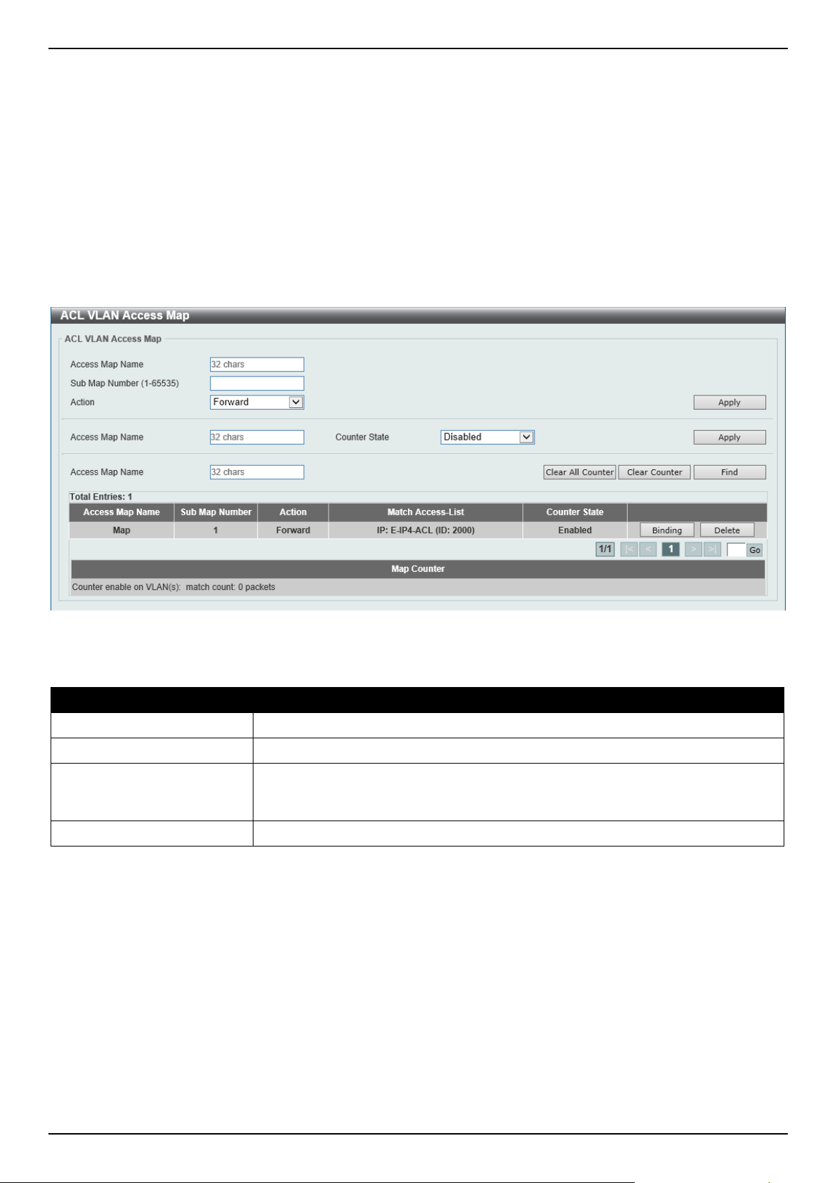
DGS-1520 Series Gigabit Ethernet Smart Managed Switch Web UI Reference Guide
397
Select the radio button next to the entry to use that ACL in the configuration.
Enter a page number and click the Go button to navigate to a specific page when multiple pages exist.
Click the OK button to accept the selection made.
ACL VLAN Access Map
This window is used to display and configure the ACL VLAN access map settings.
To view the following window, click ACL > ACL VLAN Access Map, as shown below:
Figure 8-22 ACL VLAN Access Map Window
The fields that can be configured are described below:
Parameter Description
Access Map Name
Enter the access map name here. This name can be up to 32 characters long.
Sub Map Number
Enter the sub-map number here. This value must be between 1 and 65535.
Action Select the action that will be taken here. Options to choose from are Forward,
Drop, and Redirect. When the Redirect option is selected, select the redirected
interface from the drop-down list.
Counter State
Select whether to enable or disable the counter state.
Click the Apply button to accept the changes made.
Click the Clear All Counter button to clear the counter information for all the access maps.
Click the Clear Counter button to the clear the counter information for the specified access map.
Click the Find button to locate a specific entry based on the information entered.
Click the Binding button to match an access list to the ACL VLAN access map.
Click the Delete button to remove the specific entry.
Enter a page number and click the Go button to navigate to a specific page when multiple pages exist.
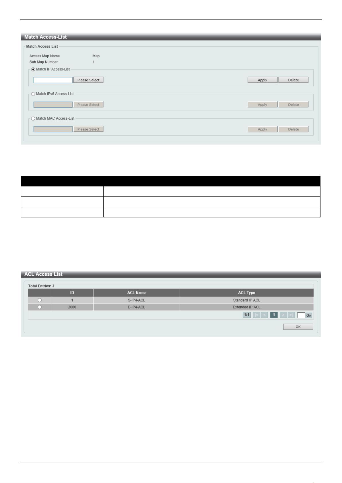
DGS-1520 Series Gigabit Ethernet Smart Managed Switch Web UI Reference Guide
398
After clicking the Binding button, the following window will appear:
Figure 8-23 ACL VLAN Access Map (Binding) Window
The fields that can be configured are described below:
Parameter Description
Match IP Access-List
Here the IP access list that will be matched will be displayed.
Match IPv6 Access-List
Here the IPv6 access list that will be matched will be displayed.
Match MAC Access-List
Here the MAC access list that will be matched will be displayed.
Click the Please Select button navigate to a list of access lists to be used in this configuration.
Click the Apply button to accept the changes made.
Click the Delete button to remove the specific entry.
After clicking the Please Select button, the following window will appear:
Figure 8-24 ACL VLAN Access Map (Binding, Selection) Window
Select the radio button next to the entry to use that access list in the configuration.
Enter a page number and click the Go button to navigate to a specific page when multiple pages exist.
Click the OK button to accept the selection made.
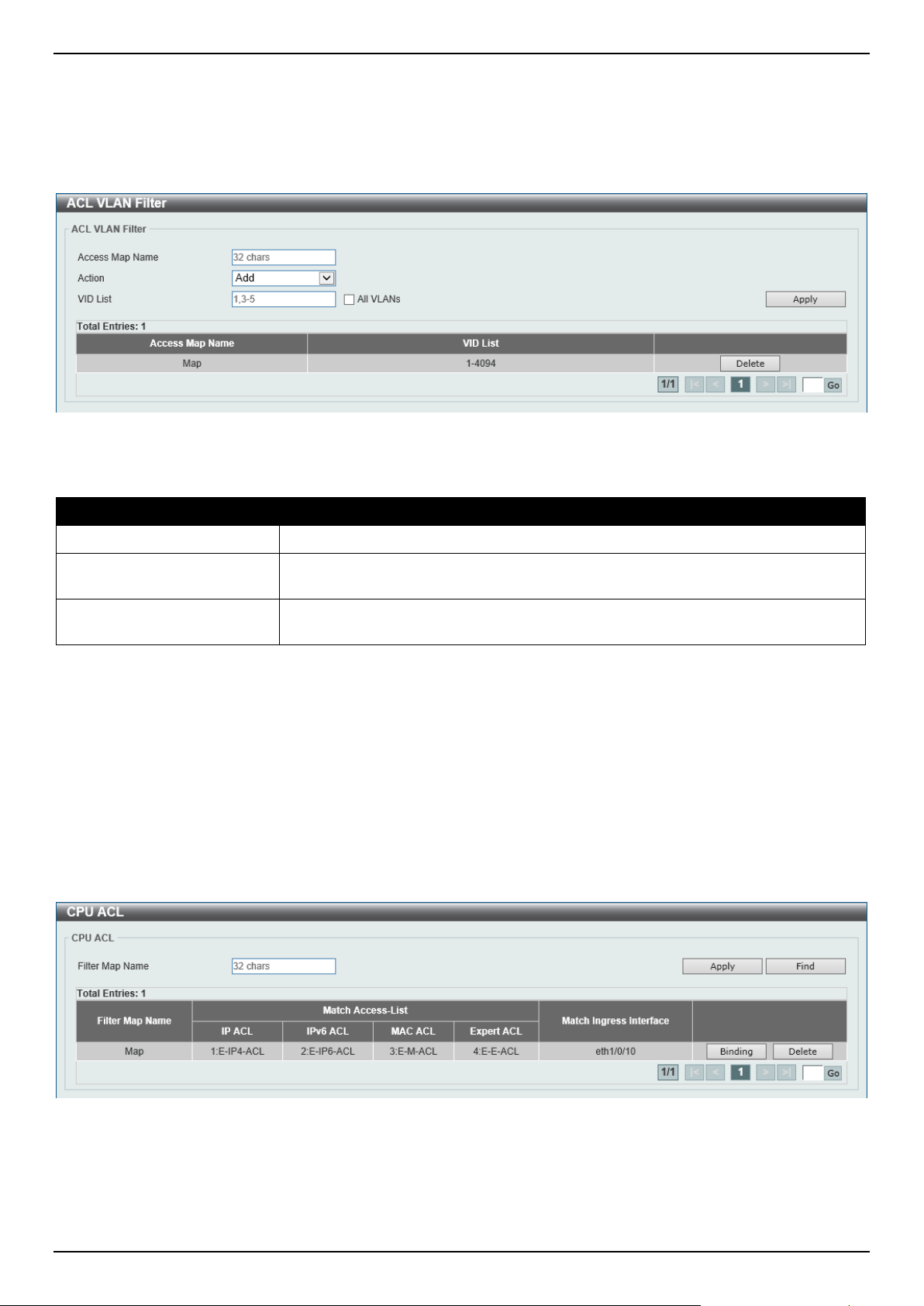
DGS-1520 Series Gigabit Ethernet Smart Managed Switch Web UI Reference Guide
399
ACL VLAN Filter
This window is used to display and configure the ACL VLAN filter settings.
To view the following window, click ACL > ACL VLAN Filter, as shown below:
Figure 8-25 ACL VLAN Filter Window
The fields that can be configured are described below:
Parameter Description
Access Map Name
Enter the access map name here. This name can be up to 32 characters long.
Action Select the action that will be taken here. Options to choose from are Add and
Delete.
VID List Enter the VLAN ID list that will be used here. Select the All VLANs option to apply
this configuration to all the VLANs configured on this Switch.
Click the Apply button to accept the changes made.
Click the Delete button to remove the specific entry.
Enter a page number and click the Go button to navigate to a specific page when multiple pages exist.
CPU ACL
This window is used to display and configure the CPU ACL settings.
To view the following window, click ACL > CPU ACL, as shown below:
Figure 8-26 CPU ACL Window
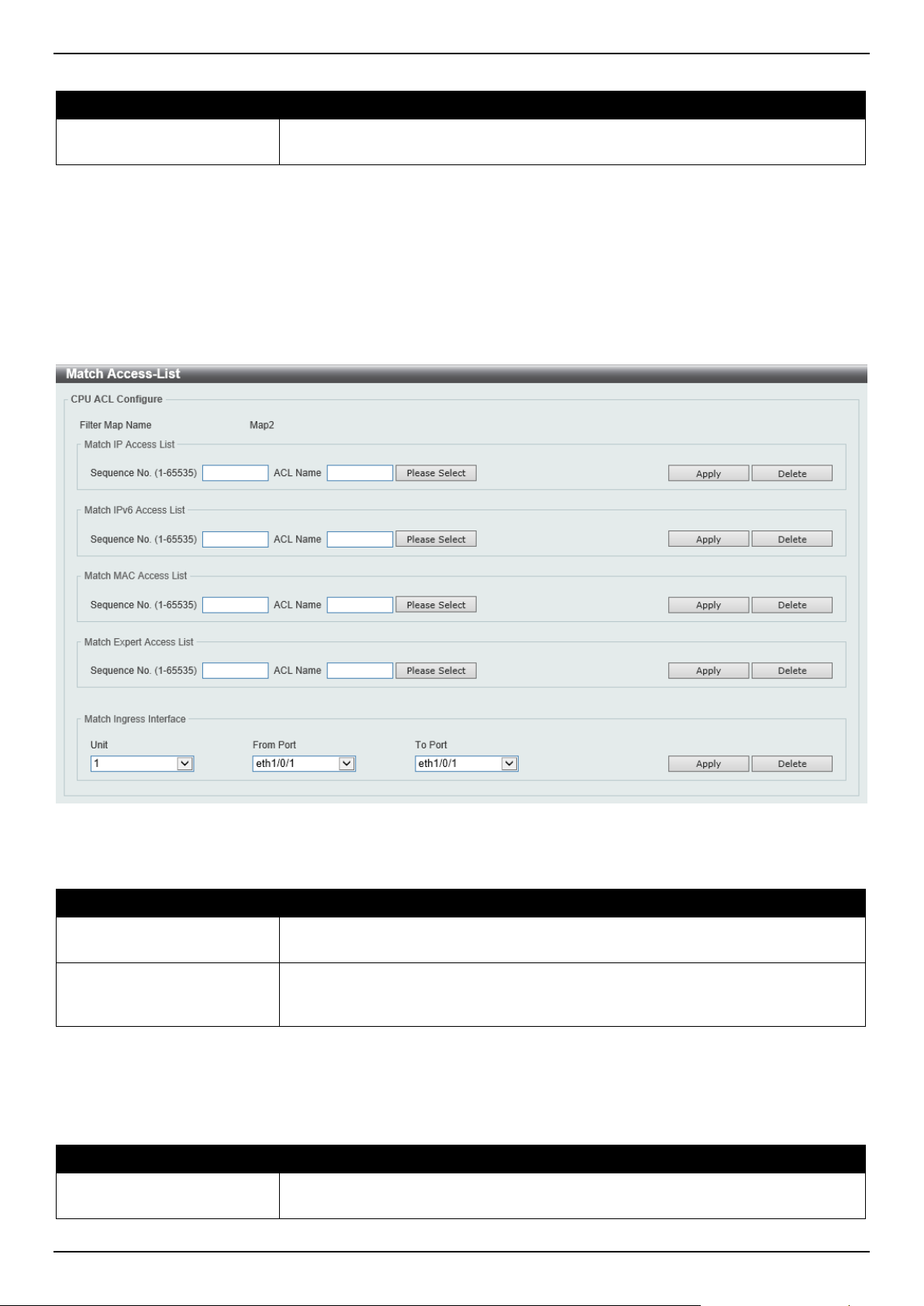
DGS-1520 Series Gigabit Ethernet Smart Managed Switch Web UI Reference Guide
400
The fields that can be configured are described below:
Parameter Description
Filter Map Name
Enter the CPU ACL filter map name here. This name can be up to 32 characters
long.
Click the Apply button to accept the changes made.
Click the Find button to locate a specific entry based on the information entered.
Click the Binding button to configure the binding settings for the specified entry.
Click the Delete button to delete the specified entry.
Enter a page number and click the Go button to navigate to a specific page when multiple pages exist.
After clicking the Binding button, the following page will appear.
Figure 8-27 CPU ACL (Binding) Window
The fields that can be configured in Match IP Access List are described below:
Parameter Description
Sequence No.
Enter the sequence number of the associated match entry here. The range is from
1 to 65535. The lower the number is, the higher the priority of the access list.
ACL Name
Enter the standard or extended IP access list name to be matched here. This
name can be up to 32 characters long. Alternatively, click the Please Select button
to select an existing ACL from the list.
Click the Apply button to accept the changes made.
Click the Delete button to delete the specified entry.
The fields that can be configured in Match IPv6 Access List are described below:
Parameter Description
Sequence No.
Enter the sequence number of the associated match entry here. The range is from
1 to 65535. The lower the number is, the higher the priority of the access list.
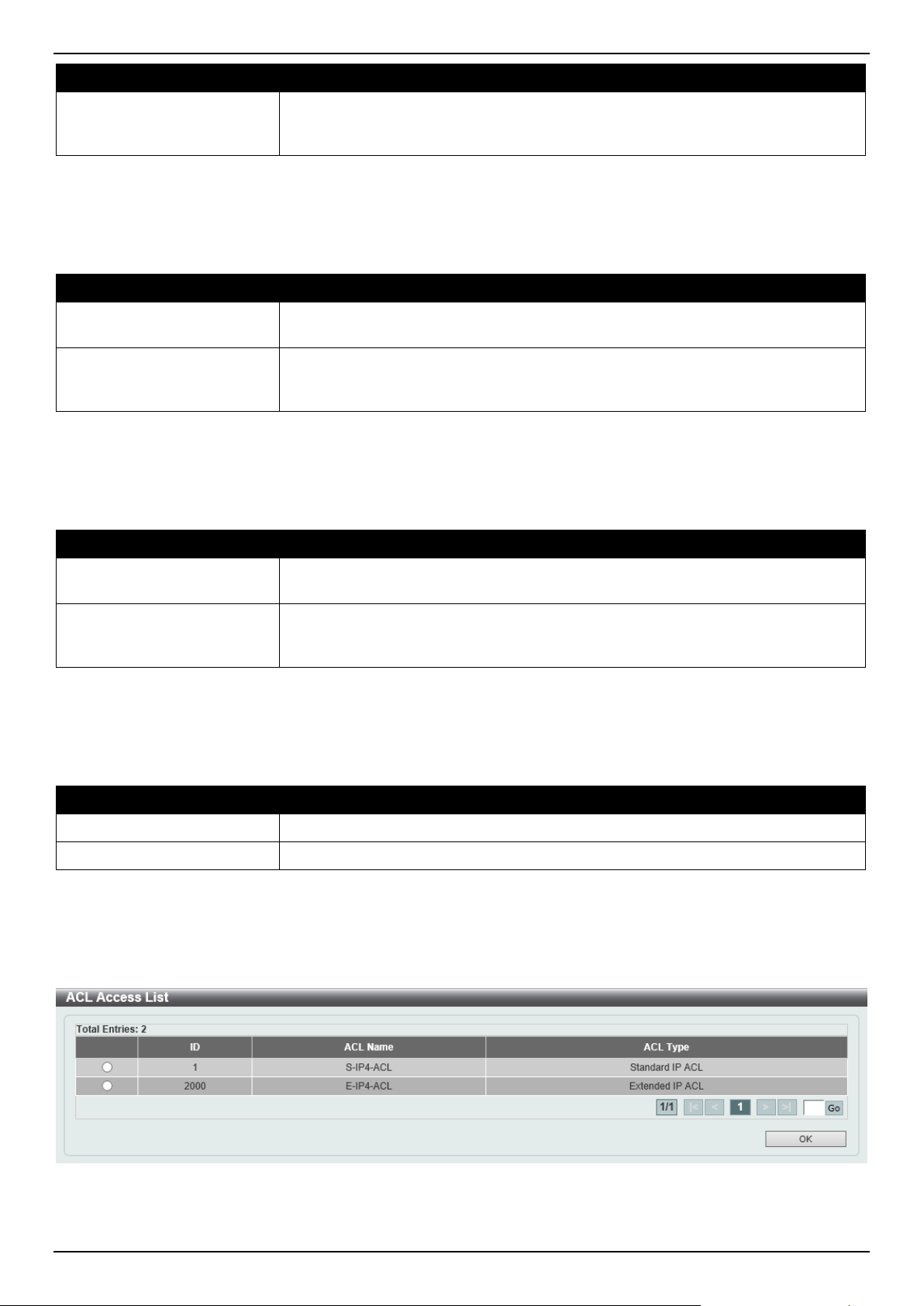
DGS-1520 Series Gigabit Ethernet Smart Managed Switch Web UI Reference Guide
401
Parameter Description
ACL Name
Enter the standard or extended IPv6 access list name to be matched here. This
name can be up to 32 characters long. Alternatively, click the Please Select button
to select an existing ACL from the list.
Click the Apply button to accept the changes made.
Click the Delete button to delete the specified entry.
The fields that can be configured in Match MAC Access List are described below:
Parameter Description
Sequence No.
Enter the sequence number of the associated match entry here. The range is from
1 to 65535. The lower the number is, the higher the priority of the access list.
ACL Name
Enter the extended MAC access list name to be matched here. This name can be
up to 32 characters long. Alternatively, click the Please Select button to select an
existing ACL from the list.
Click the Apply button to accept the changes made.
Click the Delete button to delete the specified entry.
The fields that can be configured in Match Expert Access List are described below:
Parameter Description
Sequence No.
Enter the sequence number of the associated match entry here. The range is from
1 to 65535. The lower the number is, the higher the priority of the access list.
ACL Name
Enter the extended expert access list name to be matched here. This name can be
up to 32 characters long. Alternatively, click the Please Select button to select an
existing ACL from the list.
Click the Apply button to accept the changes made.
Click the Delete button to delete the specified entry.
The fields that can be configured in Match Ingress Interface are described below:
Parameter Description
Unit
Select the Switch unit ID that will be used here.
From Port - To Port
Select the Switch port range that will be used here.
Click the Apply button to accept the changes made.
Click the Delete button to delete the specified entry.
After clicking the Please Select button, the following window will appear:
Figure 8-28 CPU ACL (Binding, Please Select) Window

DGS-1520 Series Gigabit Ethernet Smart Managed Switch Web UI Reference Guide
402
The fields that can be configured are described below:
Parameter Description
ACL List
Select the radio button next to the access list entry to use that access list in the
configuration.
Select the ACL and click the OK button to accept the selection made.
Enter a page number and click the Go button to navigate to a specific page when multiple pages exist.
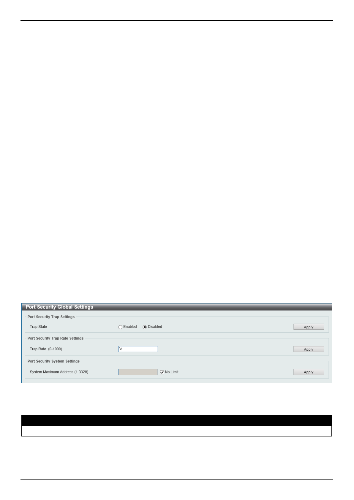
DGS-1520 Series Gigabit Ethernet Smart Managed Switch Web UI Reference Guide
403
9. Security
Port Security
802.1X
AAA
RADIUS
TACACS+
IMPB
DHCP Server Screening
ARP Spoofing Prevention
BPDU Attack Protection
NetBIOS Filtering
MAC Authentication
Web-based Access Control
Network Access Authentication
Safeguard Engine
Trusted Host
Traffic Segmentation Settings
Storm Control Settings
DoS Attack Prevention Settings
Zone Defense Settings
SSH
SSL
SFTP Server Settings
Network Protocol Port Protect Settings
Port Security
Port Security Global Settings
This window is used to display and configure the global port security settings. Port Security is a security feature that
prevents unauthorized computers (with source MAC addresses) unknown to the Switch prior to locking the port (or
ports) from connecting to the Switch's locked ports and gaining access to the network.
To view the following window, click Security > Port Security > Port Security Global Settings, as shown below:
Figure 9-1 Port Security Global Settings Window
The fields that can be configured in Port Security Trap Settings are described below:
Parameter Description
Trap State
Select to enable or disable port security traps on the Switch.
Click the Apply button to accept the changes made.
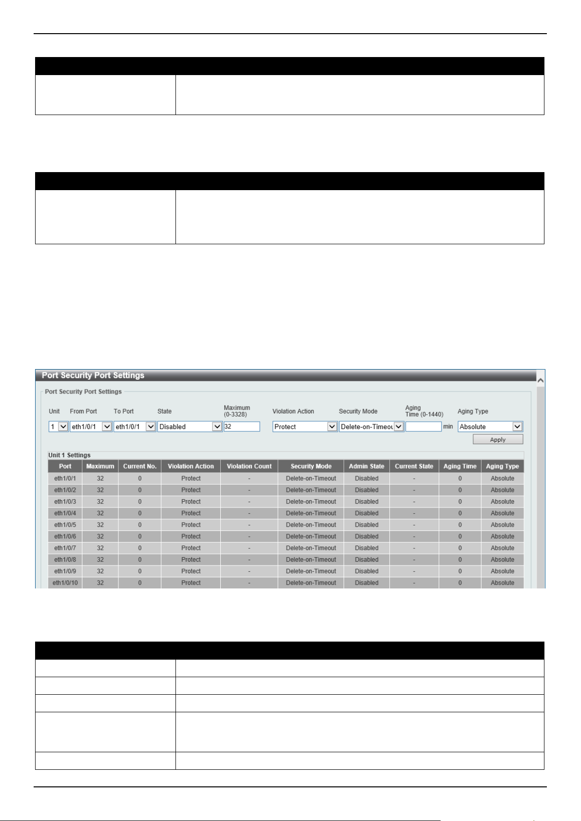
DGS-1520 Series Gigabit Ethernet Smart Managed Switch Web UI Reference Guide
404
The fields that can be configured in Port Security Trap Rate Settings are described below:
Parameter Description
Trap Rate
Enter the number of traps per second. The range is from 0 to 1000. By default, this
value is 31. This indicates that an SNMP trap is generated for every security
violation.
Click the Apply button to accept the changes made.
The fields that can be configured in Port Security System Settings are described below:
Parameter Description
System Maximum Address
Enter the maximum number of secure MAC addresses allowed. The range is from
1 to 3328. By default, there is no limit.
Tick the No Limit checkbox to allow the maximum number of secure MAC
address.
Click the Apply button to accept the changes made.
Port Security Port Settings
This window is used to display and configure the port security port settings.
To view the following window, click Security > Port Security > Port Security Port Settings, as shown below:
Figure 9-2 Port Security Port Settings Window
The fields that can be configured are described below:
Parameter Description
Unit
Select the Switch unit that will be used for this configuration here.
From Port - To Port
Select the appropriate port range used for the configuration here.
State
Select to enable or disable the port security feature on the port(s) specified.
Maximum
Enter the maximum number of secure MAC addresses that will be allowed on the
port(s) specified. This value must be between 0 and 3328. By default, this value is
32.
Violation Action
Select the violation action that will be taken here. Options to choose from are:
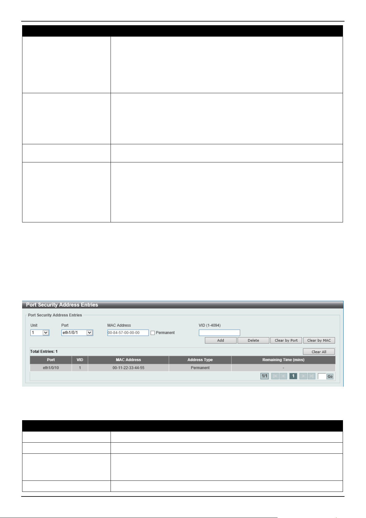
DGS-1520 Series Gigabit Ethernet Smart Managed Switch Web UI Reference Guide
405
Parameter Description
• Protect - Specifies to drop all packets from the insecure hosts at the port-
security process level, but does not increment the security-violation count.
• Restrict - Specifies to drop all packets from the insecure hosts at the port-
security process level and increments the security-violation count and
record the system log.
• Shutdown - Specifies to shut down the port if there is a security violation
and record the system log.
Security Mode
Select the security mode option here. Options to choose from are:
• Permanent - Specifies that under this mode, all learned MAC addresses are
not be purged out unless the user manually deletes those entries.
• Delete-on-Timeout - Specifies that under this mode, all learned MAC
addresses are purged out when an entry is aged out or when the user
manually deletes these entries.
Aging Time
Enter the aging time value used for auto-learned dynamic secured addresses on
the specified port here. This value must be between 0 and 1440 minutes.
Aging Type
Select the aging type here. Options to choose from are:
• Absolute - Specifies that all the secure addresses on this port age out
exactly after the time specified and is removed from the secure address list.
• Inactivity - Specifies that the secure addresses on this port age out only if
there is no data traffic from the secure source address for the specified time
period.
By default, the Absolute option is used.
Click the Apply button to accept the changes made.
Port Security Address Entries
This window is used to view, clear, and configure the port security address entries.
To view the following window, click Security > Port Security > Port Security Address Entries, as shown below:
Figure 9-3 Port Security Address Entries Window
The fields that can be configured are described below:
Parameter Description
Unit
Select the Switch unit that will be used for this configuration here.
Port
Select the appropriate port range used for the configuration here.
MAC Address
Enter the MAC address here.
Select Permanent to specify that all learned MAC addresses are purged out
unless the user manually deletes those entries.
VID
Enter the VLAN ID here. This value must be between 1 and 4094.
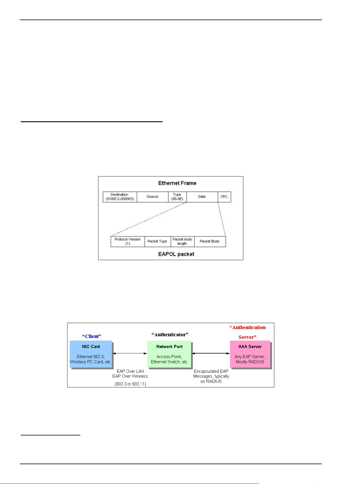
DGS-1520 Series Gigabit Ethernet Smart Managed Switch Web UI Reference Guide
406
Click the Add button to add a new entry based on the information entered.
Click the Delete button to remove a new entry based on the information entered.
Click the Clear by Port button to clear the information based on the port selected.
Click the Clear by MAC button to clear the information based on the MAC address entered.
Click the Clear All button to clear all the information in this table.
Enter a page number and click the Go button to navigate to a specific page when multiple pages exist.
802.1X
802.1X (Port-based and Host-based Access Control)
The IEEE 802.1X standard is a security measure for authorizing and authenticating users to gain access to various
wired or wireless devices on a specified Local Area Network by using a Client and Server based access control
model. This is accomplished by using a RADIUS server to authenticate users trying to access a network by relaying
Extensible Authentication Protocol over LAN (EAPOL) packets between the Client and the Server.
The following figure represents a basic EAPOL packet:
Figure 9-4 The EAPOL Packet
Utilizing this method, unauthorized devices are restricted from connecting to a LAN through a port to which the user is
connected. EAPOL packets are the only traffic that can be transmitted through the specific port until authorization is
granted. The 802.1X access control method has three roles, each of which are vital to creating and up keeping a
stable and working Access Control security method.
Figure 9-5 The three roles of 802.1X
The following section will explain the three roles of Client, Authenticator, and Authentication Server in greater detail.
Authentication Server
The Authentication Server is a remote device that is connected to the same network as the Client and Authenticator,
must be running a RADIUS Server program and must be configured properly on the Authenticator (Switch). Clients
connected to a port on the Switch must be authenticated by the Authentication Server (RADIUS) before attaining any
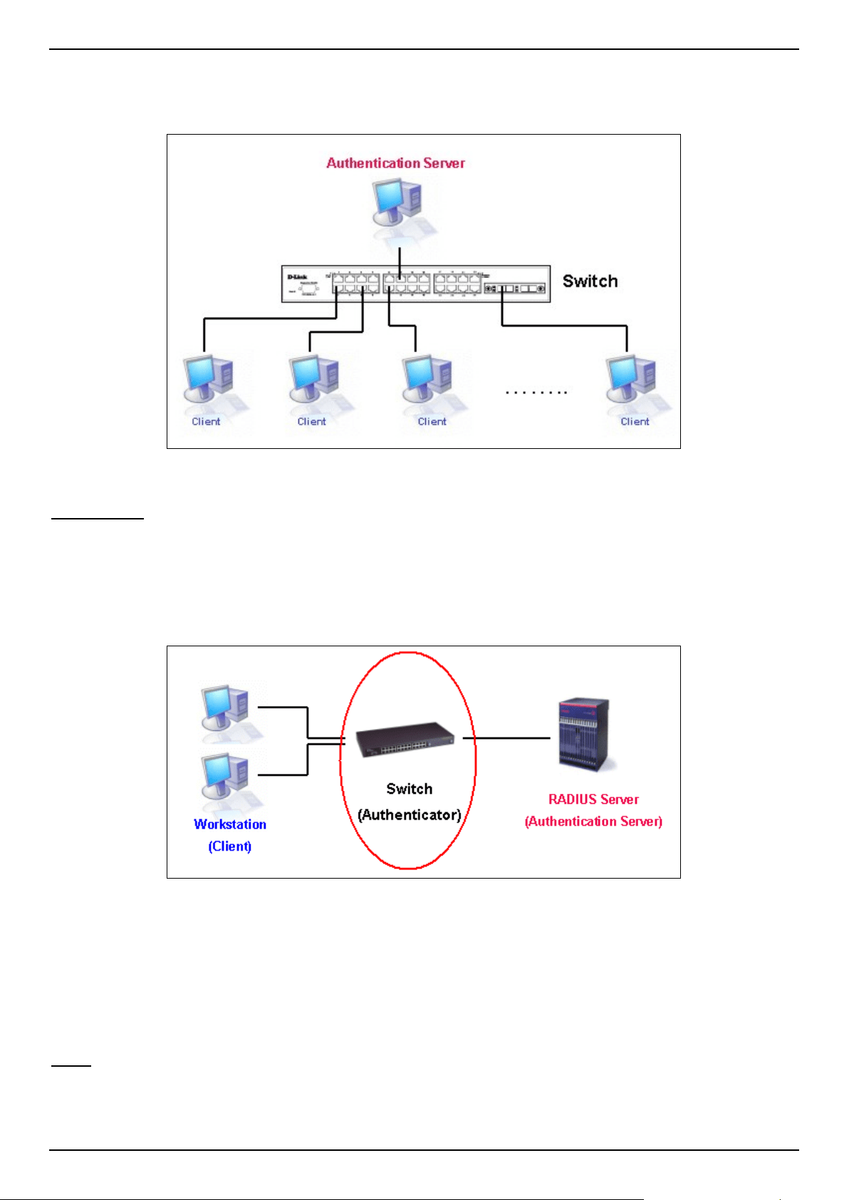
DGS-1520 Series Gigabit Ethernet Smart Managed Switch Web UI Reference Guide
407
services offered by the Switch on the LAN. The role of the Authentication Server is to certify the identity of the Client
attempting to access the network by exchanging secure information between the RADIUS server and the Client
through EAPOL packets and, in turn, informs the Switch whether or not the Client is granted access to the LAN and/or
Switches services.
Figure 9-6 The Authentication Server
Authenticator
The Authenticator (the Switch) is an intermediary between the Authentication Server and the Client. The Authenticator
serves two purposes when utilizing the 802.1X function. The first purpose is to request certification information from
the Client through EAPOL packets, which is the only information allowed to pass through the Authenticator before
access is granted to the Client. The second purpose of the Authenticator is to verify the information gathered from the
Client with the Authentication Server, and to then relay that information back to the Client.
Figure 9-7 The Authenticator
Three steps must be implemented on the Switch to properly configure the Authenticator.
• The 802.1X State must be Enabled. (Security > 802.1X > 802.1X Global Settings)
• The 802.1X settings must be implemented by port (Security > 802.1X > 802.1X Port Settings)
• A RADIUS server must be configured on the Switch. (Security > RADIUS > RADIUS Server Settings)
Client
The Client is simply the end station that wishes to gain access to the LAN or Switch services. All end stations must be
running software that is compliant with the 802.1X protocol. For users running Windows 7 and later, that software is
included within the operating system. All other users are required to attain 802.1X client software from an outside
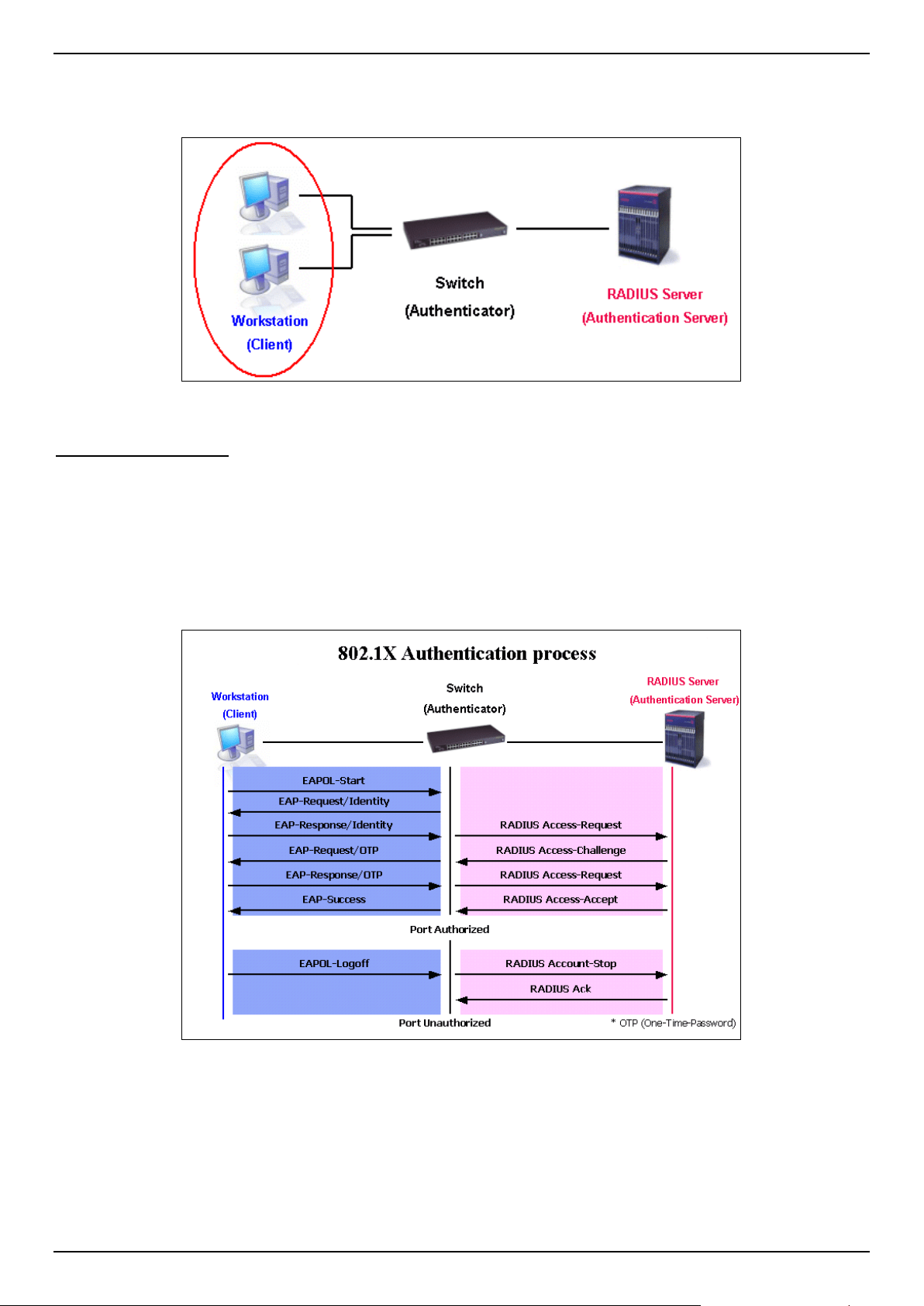
DGS-1520 Series Gigabit Ethernet Smart Managed Switch Web UI Reference Guide
408
source. The Client will request access to the LAN and or Switch through EAPOL packets and, in turn will respond to
requests from the Switch.
Figure 9-8 The Client
Authentication Process
Utilizing the three roles stated above, the 802.1X protocol provides a stable and secure way of authorizing and
authenticating users attempting to access the network. Only EAPOL traffic is allowed to pass through the specified
port before a successful authentication is made. This port is "locked" until the point when a Client with the correct
username and password (and MAC address if 802.1X is enabled by MAC address) is granted access and therefore
successfully "unlocks" the port. Once the port is unlocked, normal traffic is allowed to pass through the port. The
following figure displays a detailed explanation of how the authentication process is completed between the three
roles stated above.
Figure 9-9 The 802.1X Authentication Process
The D-Link implementation of 802.1X allows network administrators to choose between two types of Access Control
used on the Switch, which are:
• Port-based Access Control - This method requires only one user to be authenticated per port by a remote
RADIUS server to allow the remaining users on the same port access to the network.
• Host-based Access Control - Using this method, the Switch will automatically learn up to a maximum of 4096
MAC addresses by port and set them in a list. Each MAC address must be authenticated by the Switch using a
remote RADIUS server before being allowed access to the Network.
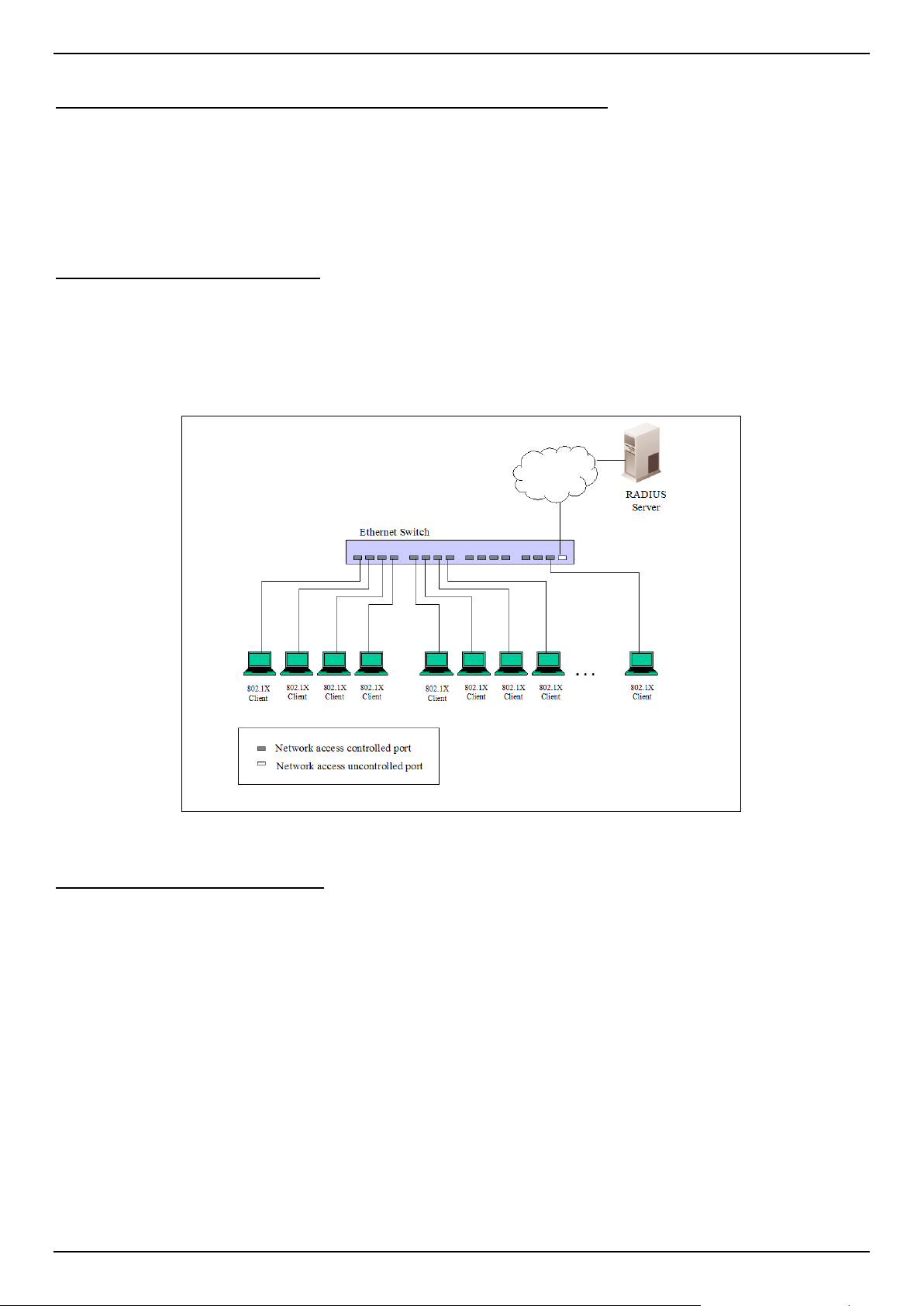
DGS-1520 Series Gigabit Ethernet Smart Managed Switch Web UI Reference Guide
409
Understanding 802.1X Port-based and Host-based Network Access Control
The original intent behind the development of 802.1X was to leverage the characteristics of point-to-point in LANs. As
any single LAN segment in such infrastructures has no more than two devices attached to it, one of which is a Bridge
Port. The Bridge Port detects events that indicate the attachment of an active device at the remote end of the link, or
an active device becoming inactive. These events can be used to control the authorization state of the Port and initiate
the process of authenticating the attached device if the Port is unauthorized. This is the Port-based Network Access
Control.
Port-based Network Access Control
Once the connected device has successfully been authenticated, the Port then becomes Authorized, and all
subsequent traffic on the Port is not subject to access control restriction until an event occurs that causes the Port to
become Unauthorized. Hence, if the Port is actually connected to a shared media LAN segment with more than one
attached device, successfully authenticating one of the attached devices effectively provides access to the LAN for all
devices on the shared segment. Clearly, the security offered in this situation is open to attack.
Figure 9-10 Example of Typical Port-based Configuration
Host-based Network Access Control
In order to successfully make use of 802.1X in a shared media LAN segment, it would be necessary to create "logical"
Ports, one for each attached device that required access to the LAN. The Switch would regard the single physical Port
connecting it to the shared media segment as consisting of a number of distinct logical Ports, each logical Port being
independently controlled from the point of view of EAPOL exchanges and authorization state. The Switch learns each
attached devices' individual MAC addresses, and effectively creates a logical Port that the attached device can then
use to communicate with the LAN via the Switch.
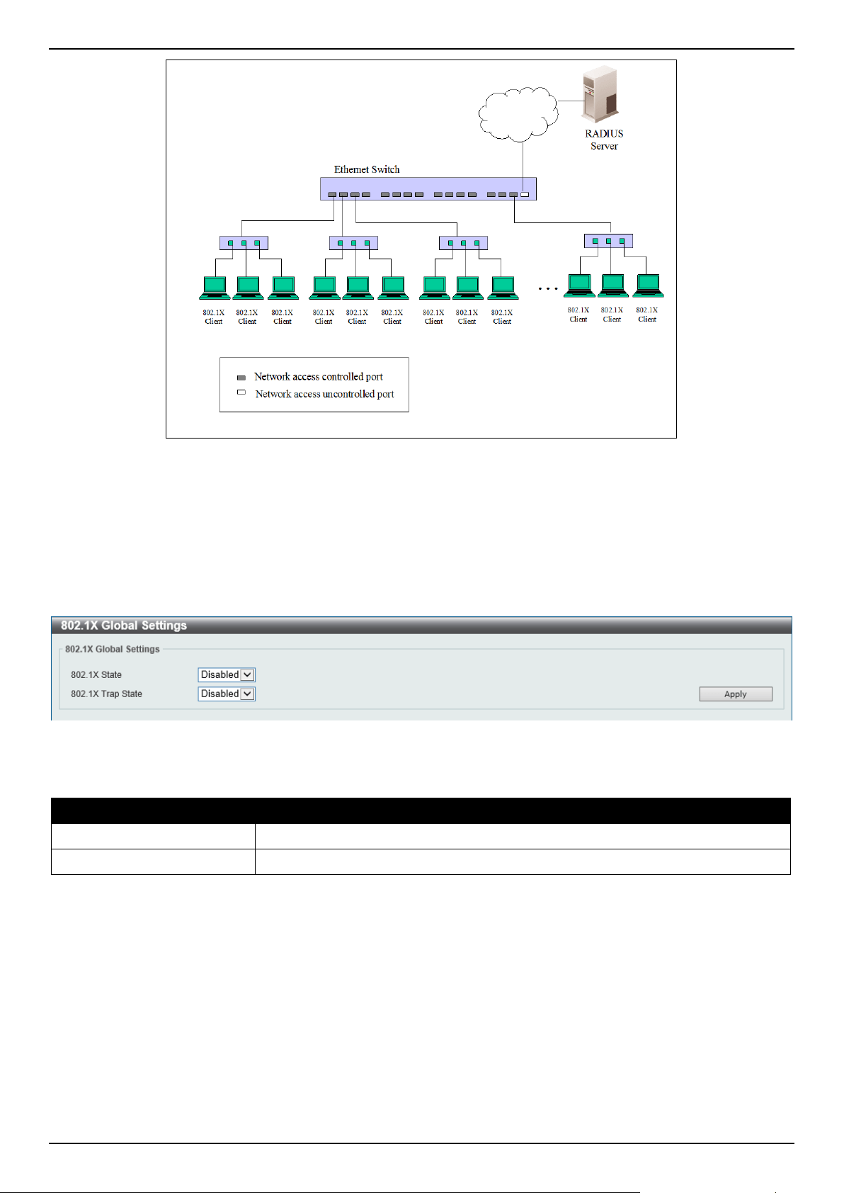
DGS-1520 Series Gigabit Ethernet Smart Managed Switch Web UI Reference Guide
410
Figure 9-11 Example of Typical Host-based Configuration
802.1X Global Settings
This window is used to display and configure the global 802.1X settings.
To view the following window, click Security > 802.1X > 802.1X Global Settings, as shown below:
Figure 9-12 802.1X Global Settings Window
The fields that can be configured are described below:
Parameter Description
802.1X State
Select to enable or disable the global 802.1X state here.
802.1X Trap State
Select to enable or disable the 802.1X trap state here.
Click the Apply button to accept the changes made.
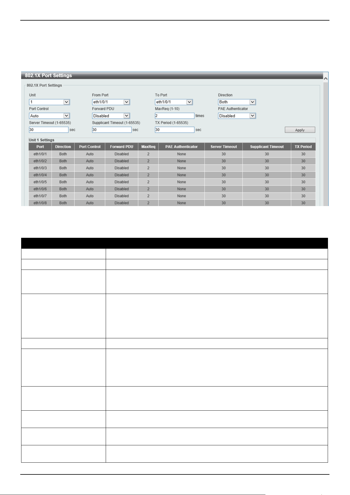
DGS-1520 Series Gigabit Ethernet Smart Managed Switch Web UI Reference Guide
411
802.1X Port Settings
This window is used to display and configure the 802.1X port settings.
To view the following window, click Security > 802.1X > 802.1X Port Settings, as shown below:
Figure 9-13 802.1X Port Settings Window
The fields that can be configured are described below:
Parameter Description
Unit
Select the Switch unit that will be used for this configuration here.
From Port - To Port
Select the appropriate port range used for the configuration here.
Direction Select the direction here. Options to choose from are Both and In. This option
configures the direction of the traffic on a controlled port as unidirectional (In) or
bidirectional (Both).
Port Control Select the port control option here. Options to choose from are ForceAuthorized,
Auto, and ForceUnauthorized. If the port control is set to force-authorized, then
the port is not controlled in both directions. If the port control is set to automatic,
then the access to the port for the controlled direction needs to be authenticated. If
the port control is set to force-unauthorized, then the access to the port for the
controlled direction is blocked.
Forward PDU
Select to enable or disable the forward PDU option here.
MaxReq
Enter the maximum required times value here. This value must be between 1 and
10. By default, this value is 2. This option configures the maximum number of
times that the backend authentication state machine will retransmit an Extensible
Authentication Protocol (EAP) request frame to the supplicant before restarting the
authentication process.
PAE Authenticator
Select to enable or disable the PAE authenticator option here. This option
configures a specific port as an IEEE 802.1X port access entity (PAE)
authenticator.
Server Timeout
Enter the server timeout value here. This value must be between 1 and 65535
seconds. By default, this value is 30 seconds.
Supplicant Timeout
Enter the supplicant timeout value here. This value must be between 1 and 65535
seconds. By default, this value is 30 seconds.
TX Period
Enter the transmission period value here. This value must be between 1 and
65535 seconds. By default, this value is 30 seconds.
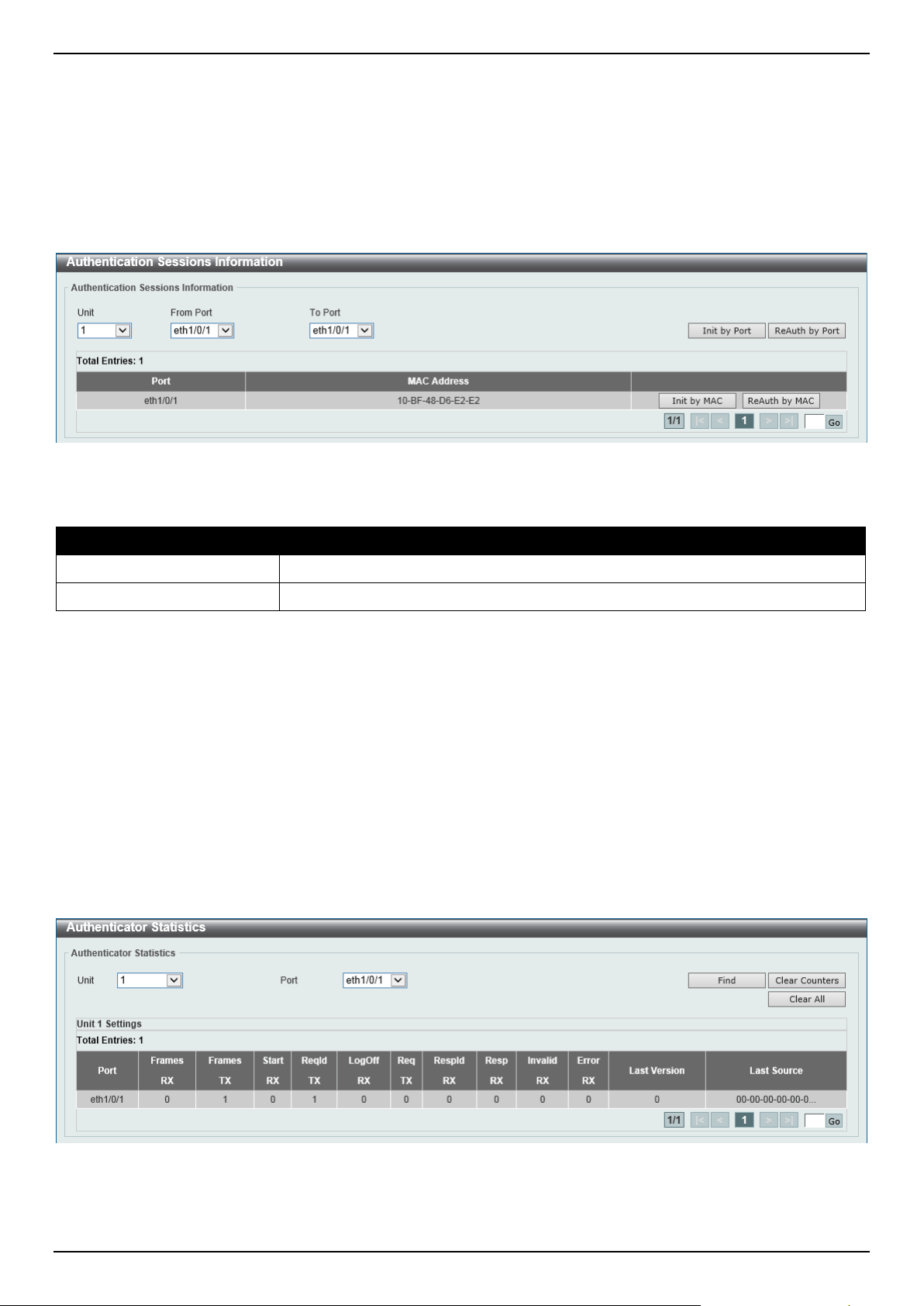
DGS-1520 Series Gigabit Ethernet Smart Managed Switch Web UI Reference Guide
412
Click the Apply button to accept the changes made.
Authentication Sessions Information
This window is used to display and configure the authentication session information.
To view the following window, click Security > 802.1X > Authentication Sessions Information, as shown below:
Figure 9-14 Authentication Sessions Information Window
The fields that can be configured are described below:
Parameter Description
Unit
Select the Switch unit that will be used for this configuration here.
From Port - To Port
Select the appropriate port range used for the configuration here.
Click the Init by Port button to initiate the session information based on the port selections made.
Click the ReAuth by Port button to re-authenticate the session information based on the port selections made.
Click the Init by MAC button to initiate the session information based on the MAC address.
Click the ReAuth by MAC button to re-authenticate the session information based on the MAC address.
Enter a page number and click the Go button to navigate to a specific page when multiple pages exist.
Authenticator Statistics
This window is used to view and clear the authenticator statistics.
To view the following window, click Security > 802.1X > Authenticator Statistics, as shown below:
Figure 9-15 Authenticator Statistics Window
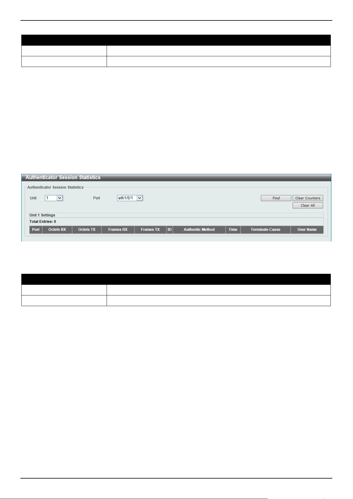
DGS-1520 Series Gigabit Ethernet Smart Managed Switch Web UI Reference Guide
413
The fields that can be configured are described below:
Parameter Description
Unit
Select the Switch unit that will be used for this query here.
Port
Select the appropriate port used for the query here.
Click the Find button to locate a specific entry based on the information entered.
Click the Clear Counters button to clear the counter information based on the selections made.
Click the Clear All button to clear all the information in this table.
Enter a page number and click the Go button to navigate to a specific page when multiple pages exist.
Authenticator Session Statistics
This window is used to view and clear the authenticator session statistics.
To view the following window, click Security > 802.1X > Authenticator Session Statistics, as shown below:
Figure 9-16 Authenticator Session Statistics Window
The fields that can be configured are described below:
Parameter Description
Unit
Select the Switch unit that will be used for this query here.
Port
Select the appropriate port used for the query here.
Click the Find button to locate a specific entry based on the information entered.
Click the Clear Counters button to clear the counter information based on the selections made.
Click the Clear All button to clear all the information in this table.
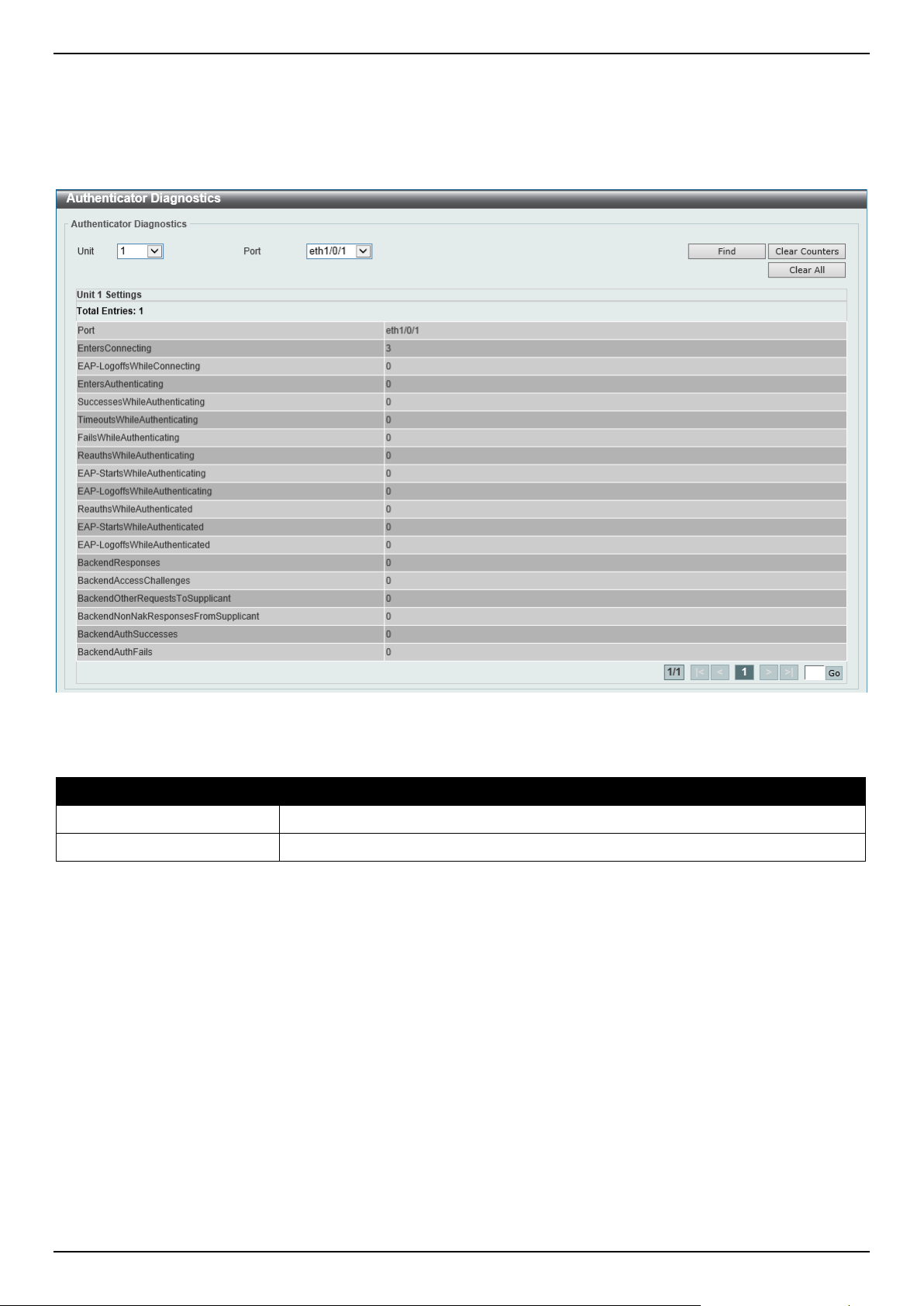
DGS-1520 Series Gigabit Ethernet Smart Managed Switch Web UI Reference Guide
414
Authenticator Diagnostics
This window is used to view and clear the authenticator diagnostics information.
To view the following window, click Security > 802.1X > Authenticator Diagnostics, as shown below:
Figure 9-17 Authenticator Diagnostics Window
The fields that can be configured are described below:
Parameter Description
Unit
Select the Switch unit that will be used for this query here.
Port
Select the appropriate port used for the query here.
Click the Find button to locate a specific entry based on the information entered.
Click the Clear Counters button to clear the counter information based on the selections made.
Click the Clear All button to clear all the information in this table.
Enter a page number and click the Go button to navigate to a specific page when multiple pages exist.
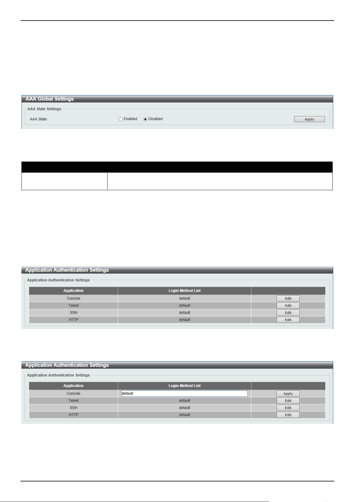
DGS-1520 Series Gigabit Ethernet Smart Managed Switch Web UI Reference Guide
415
AAA
AAA Global Settings
This window is used to enable or disable the global Authentication, Authorization, and Accounting (AAA) state.
To view the following window, click Security > AAA > AAA Global Settings, as shown below:
Figure 9-18 AAA Global Settings Window
The fields that can be configured are described below:
Parameter Description
AAA State
Select to enable or disable the global Authentication, Authorization, and
Accounting (AAA) state.
Click the Apply button to accept the changes made.
Application Authentication Settings
This window is used to display and configure the application authentication settings.
To view the following window, click Security > AAA > Application Authentication Settings, as shown below:
Figure 9-19 Application Authentication Settings Window
Click the Edit button to re-configure the specific entry.
Figure 9-20 Application Authentication Settings (Edit) Window
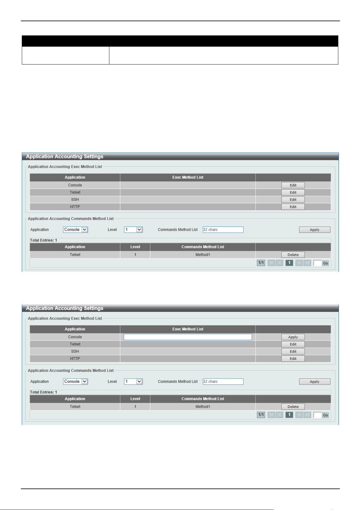
DGS-1520 Series Gigabit Ethernet Smart Managed Switch Web UI Reference Guide
416
The fields that can be configured are described below:
Parameter Description
Login Method List After clicking the Edit button for the specific entry, enter the login method list name
used here.
Click the Edit button to re-configure the specific entry.
Click the Apply button to accept the changes made.
Application Accounting Settings
This window is used to display and configure the application accounting settings.
To view the following window, click Security > AAA > Application Accounting Settings, as shown below:
Figure 9-21 Application Accounting Settings Window
Click the Edit button to re-configure the specific entry.
Figure 9-22 Application Accounting Settings (Edit) Window
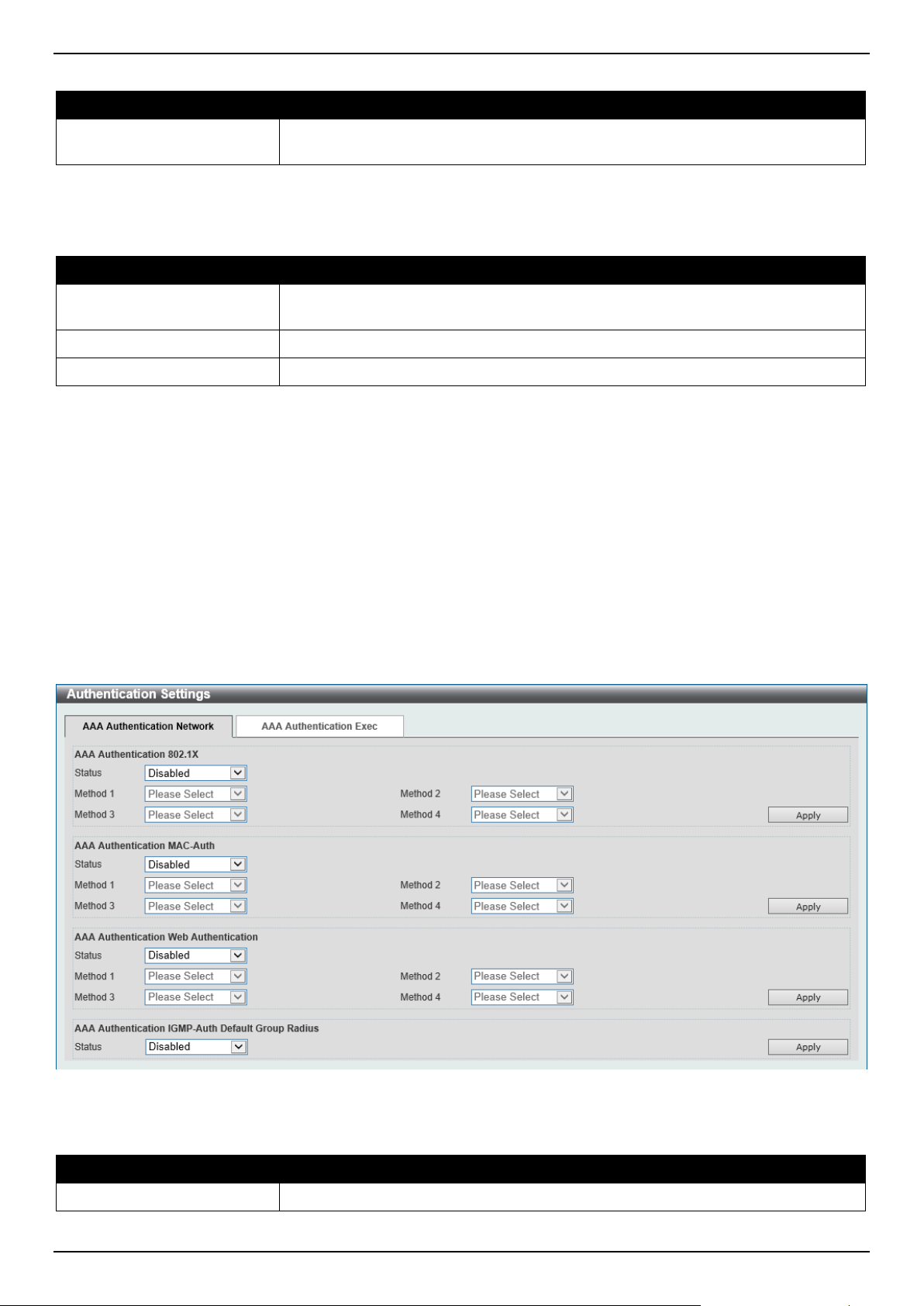
DGS-1520 Series Gigabit Ethernet Smart Managed Switch Web UI Reference Guide
417
The fields that can be configured in Application Accounting Exec Method list are described below:
Parameter Description
Exec Method List After clicking the Edit button for the specific entry, enter the EXEC method list
name used here.
Click the Apply button to accept the changes made.
The fields that can be configured in Application Accounting Commands Method List are described below:
Parameter Description
Application Select the application used here. Options to choose from are Console, Telnet,
and SSH.
Level
Select the privilege level used here. Options to choose from are levels 1 to 15.
Commands Method List
Enter the commands method list name used here.
Click the Edit button to re-configure the specific entry.
Click the Apply button to accept the changes made.
Click the Delete button to remove the specified entry.
Enter a page number and click the Go button to navigate to a specific page when multiple pages exist.
Authentication Settings
This window is used to display and configure the AAA network and EXEC authentication settings.
To view the following window, click Security > AAA > Authentication Settings and select the AAA Authentication
Network tab, as shown below:
Figure 9-23 Authentication Settings Window
The fields that can be configured in AAA Authentication 802.1X are described below:
Parameter Description
Status
Select to enable or disable the AAA 802.1X authentication state here.

DGS-1520 Series Gigabit Ethernet Smart Managed Switch Web UI Reference Guide
418
Parameter Description
Method 1 ~ Method 4
Select the method lists that will be used for this configuration here. Options to
choose from are:
• none - Normally, the method is listed as the last method. The user will pass
authentication if it is not denied by previous method authentication.
• local - Specifies to use the local database for authentication.
• group - Specifies to use the server groups defined by the AAA group
server. Enter the AAA group server name in the space provided. This string
can be up to 32 characters long.
• radius - Specifies to use the servers defined by the RADIUS server host
command.
Click the Apply button to accept the changes made.
The fields that can be configured in AAA Authentication MAC-Auth are described below:
Parameter Description
Status
Select to enable or disable the AAA MAC authentication state here.
Method 1 ~ Method 4
Select the method lists that will be used for this configuration here. Options to
choose from are:
• none - Normally, the method is listed as the last method. The user will pass
authentication if it is not denied by previous method authentication.
• local - Specifies to use the local database for authentication.
• group - Specifies to use the server groups defined by the AAA group
server. Enter the AAA group server name in the space provided. This string
can be up to 32 characters long.
• radius - Specifies to use the servers defined by the RADIUS server host
command.
Click the Apply button to accept the changes made.
The fields that can be configured in AAA Authentication WEB-Auth are described below:
Parameter Description
Status
Select to enable or disable the AAA Web authentication state here.
Method 1 ~ Method 4
Select the method lists that will be used for this configuration here. Options to
choose from are:
• none - Normally, the method is listed as the last method. The user will pass
authentication if it is not denied by previous method authentication.
• local - Specifies to use the local database for authentication.
• group - Specifies to use the server groups defined by the AAA group
server. Enter the AAA group server name in the space provided. This string
can be up to 32 characters long.
• radius - Specifies to use the servers defined by the RADIUS server host
command.
Click the Apply button to accept the changes made.
The fields that can be configured in AAA Authentication IGMP-Auth Default Group RADIUS are described below:
Parameter Description
Status
Select to enable or disable the AAA authentication IGMP authentication default
group RADIUS feature here.
Click the Apply button to accept the changes made.
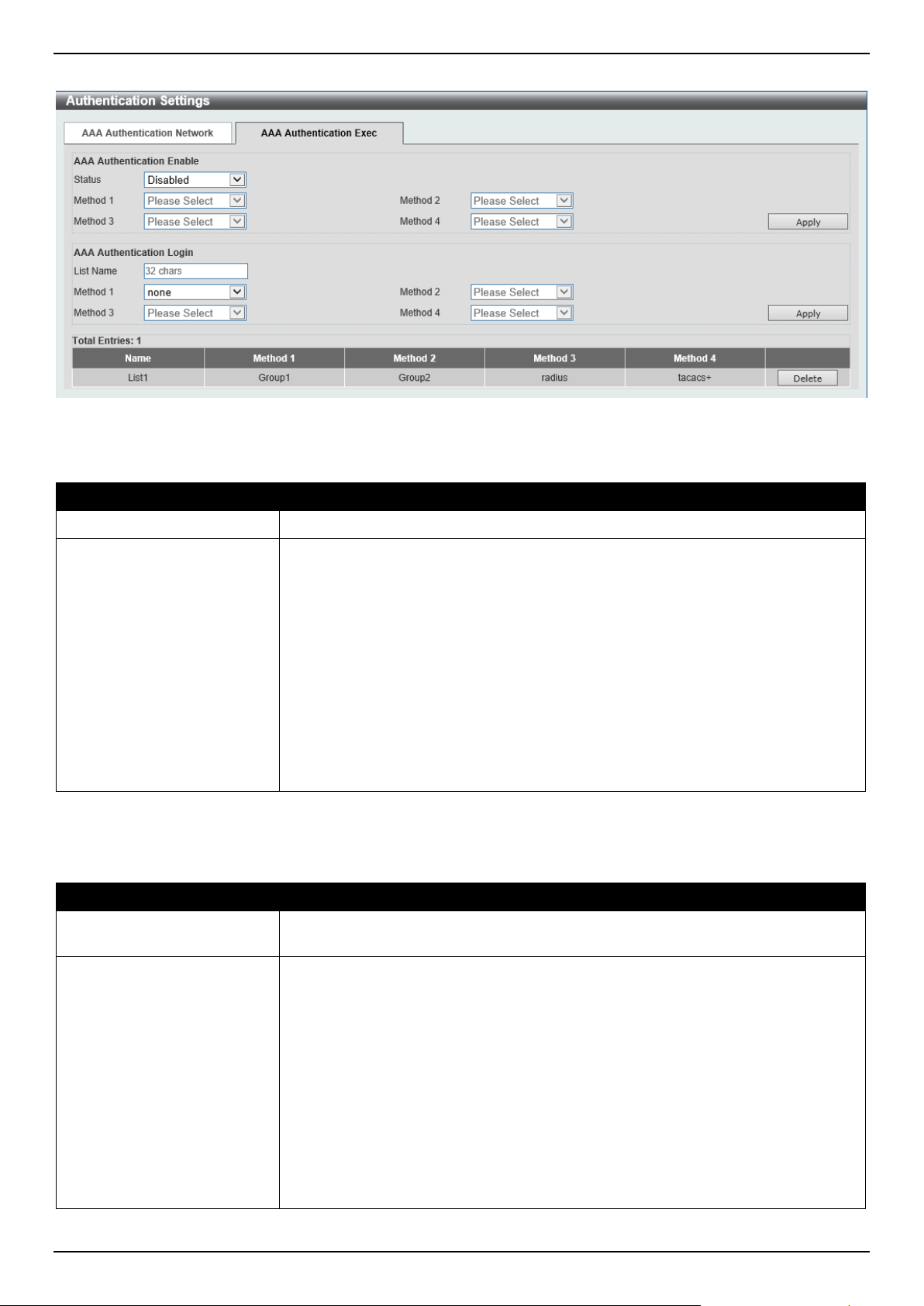
DGS-1520 Series Gigabit Ethernet Smart Managed Switch Web UI Reference Guide
419
To view the following window, select the AAA Authentication Exec tab, as shown below:
Figure 9-24 Authentication Settings (AAA Authentication EXEC) Window
The fields that can be configured in AAA Authentication Enable are described below:
Parameter Description
Status
Select to enable or disable the AAA authentication enable state here.
Method 1 ~ Method 4
Select the method lists that will be used for this configuration here. Options to
choose from are:
• none - Normally, the method is listed as the last method. The user will pass
the authentication if it is not denied by previous method authentication.
• enable - Specifies to use the local enable password for authentication.
• group - Specifies to use the server groups defined by the AAA group server
command. Enter the AAA group server name in the space provided. This
string can be up to 32 characters long.
• radius - Specifies to use the servers defined by the RADIUS server host
command.
• tacacs+ - Specifies to use the servers defined by the TACACS+ server host
command.
Click the Apply button to accept the changes made.
The fields that can be configured in AAA Authentication Login are described below:
Parameter Description
List Name
Enter the method list name that will be used with the AAA authentication login
option here.
Method 1 ~ Method 4
Select the method lists that will be used for this configuration here. Options to
choose from are:
• none - Normally, the method is listed as the last method. The user will pass
authentication if it is not denied by previous method's authentication.
• local - Specifies to use the local database for authentication.
• group - Specifies to use the server groups defined by the AAA group server
command. Enter the AAA group server name in the space provided. This
string can be up to 32 characters long.
• radius - Specifies to use the servers defined by the RADIUS server host
command.
• tacacs+ - Specifies to use the servers defined by the TACACS+ server host
command.
Click the Apply button to accept the changes made.
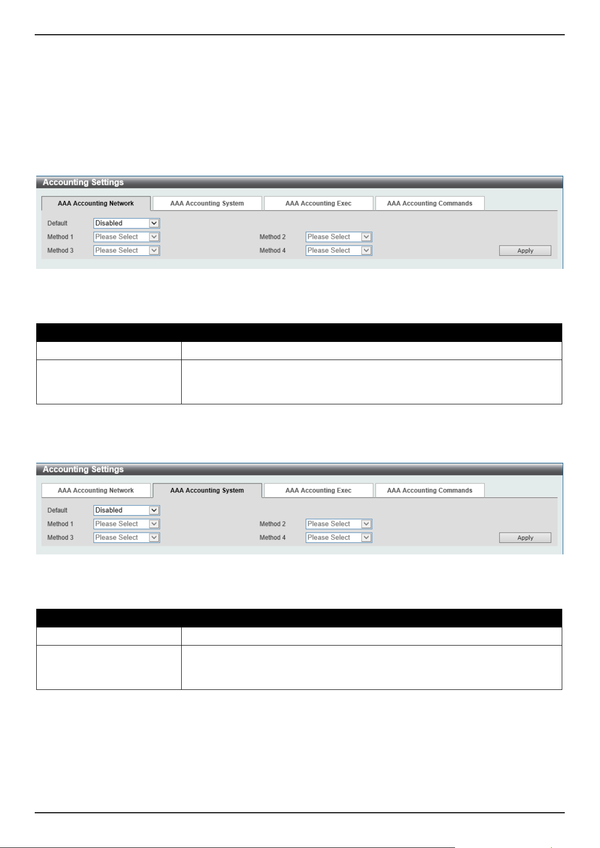
DGS-1520 Series Gigabit Ethernet Smart Managed Switch Web UI Reference Guide
420
Click the Delete button to remove the specified entry.
Accounting Settings
This window is used to display and configure the AAA accounting settings.
To view the following window, click Security > AAA > Accounting Settings and select the AAA Accounting
Network tab, as shown below:
Figure 9-25 Accounting Settings Window
The fields that can be configured in AAA Accounting Network are described below:
Parameter Description
Default
Select to enable or disable the use of the default method list here.
Method 1 ~ Method 4
Select the method lists that will be used for this configuration here. Options to
choose from are None, Group, RADIUS, and TACACS+.
The None option is only available for Method 1.
Click the Apply button to accept the changes made.
To view the following window, select the AAA Accounting System tab, as shown below:
Figure 9-26 Accounting Settings (AAA Accounting System) Window
The fields that can be configured in AAA Accounting System are described below:
Parameter Description
Default
Select to enable or disable the use of the default method list here.
Method 1 ~ Method 4
Select the method lists that will be used for this configuration here. Options to
choose from are None, Group, RADIUS, and TACACS+.
The None option is only available for Method 1.
Click the Apply button to accept the changes made.
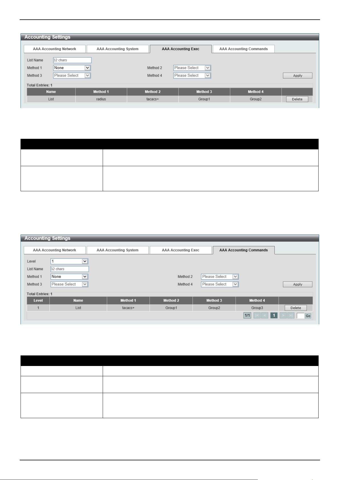
DGS-1520 Series Gigabit Ethernet Smart Managed Switch Web UI Reference Guide
421
To view the following window, select the AAA Accounting Exec tab, as shown below:
Figure 9-27 Accounting Settings (AAA Accounting Exec) Window
The fields that can be configured in AAA Accounting Exec are described below:
Parameter Description
List Name
Enter the method list name that will be used with the AAA accounting EXEC option
here.
Method 1 ~ Method 4
Select the method lists that will be used for this configuration here. Options to
choose from are None, Group, RADIUS, and TACACS+.
The None option is only available for Method 1.
Click the Apply button to accept the changes made.
Click the Delete button to remove the specified entry.
To view the following window, select the AAA Accounting Commands tab, as shown below:
Figure 9-28 Accounting Settings (AAA Accounting Commands) Window
The fields that can be configured are described below:
Parameter Description
Level
Select the privilege level used here. Options to choose from are levels 1 to 15.
List Name
Enter the method list name that will be used with the AAA accounting commands
option here.
Method 1 ~ Method 4
Select the method lists that will be used for this configuration here. Options to
choose from are None, Group, and TACACS+.
The None option is only available for Method 1.
Click the Apply button to accept the changes made.
Click the Delete button to remove the specified entry.
Enter a page number and click the Go button to navigate to a specific page when multiple pages exist.
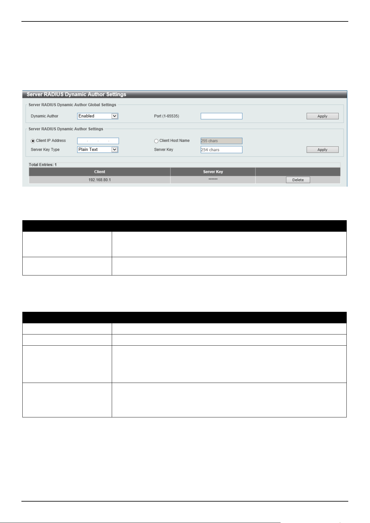
DGS-1520 Series Gigabit Ethernet Smart Managed Switch Web UI Reference Guide
422
Server RADIUS Dynamic Author Settings
This window is used to view and configure the dynamic author settings for the RADIUS server.
To view the following window, click Security > AAA > Server RADIUS Dynamic Author Settings, as shown below:
Figure 9-29 Server RADIUS Dynamic Author Settings Window
The fields that can be configured for Server RADIUS Dynamic Author Global Settings are described below:
Parameter Description
Dynamic Author
Select to enable or disable the dynamic author function here. Dynamic
authorization allows an external policy server to dynamically send updates to a
device.
Port
Enter the port number that is used for the data transmission of the update packets
here. The range is from 1 to 65535.
Click the Apply button to accept the changes made.
The fields that can be configured for Server RADIUS Dynamic Author Settings are described below:
Parameter Description
Client IP Address
Select and enter the IP address of the RADIUS client here.
Client Host Name
Select and enter the hostname of the RADIUS client here.
Server Key Type
Select the RADIUS server key type here. Options to choose from are:
• Plain Text - Select this option to use the plain text RADIUS server key type.
• Encrypted - Select this option to use the encrypted RADIUS server key
type.
Server Key When Plain Text is selected as the key type, enter the key for the RADIUS server
connection in the plain text form here. This key can be up to 32 characters long.
When Encrypted is selected as the key type, enter the key for the RADIUS server
connection in the encrypted form here. This key can be up to 64 characters long.
Click the Apply button to add a new entry.
Click the Delete button to remove the specified entry.

DGS-1520 Series Gigabit Ethernet Smart Managed Switch Web UI Reference Guide
423
RADIUS
RADIUS Global Settings
This window is used to display and configure the global RADIUS settings.
To view the following window, click Security > RADIUS > RADIUS Global Settings, as shown below:
Figure 9-30 RADIUS Global Settings Window
The fields that can be configured in RADIUS Global Settings are described below:
Parameter Description
DeadTime
Enter the dead time value here. This value must be between 1 and 1440 minutes.
By default, this value is 0 minutes. When this option is 0, the unresponsive server
will not be marked as dead. This setting can be used to improve the authentication
processing time by setting the dead time to skip the unresponsive server host
entries.
When the system performs authentication with the authentication server, it
attempts one server at a time. If the attempted server does not respond, the
system will attempt the next server. When the system finds a server does not
respond, it will mark the server as down, start a dead time timer, and skip them in
authentication of the following requests until expiration of the dead time.
Click the Apply button to accept the changes made.
The fields that can be configured in RADIUS Global IPv4 Source Interface are described below:
Parameter Description
IPv4 RADIUS Source
Interface State
Select to enable or disable the state of the IPv4 RADIUS source interface here.
IPv4 RADIUS Source
Interface Type
Select the IPv4 RADIUS source interface type here. Options to choose from are:
• Loopback - Specifies the IPv4 RADIUS source interface type as Loopback.
• VLAN - Specifies the IPv4 RADIUS source interface type as VLAN.
Interface ID
Enter the IPv4 RADIUS source interface ID here.
The Loopback interface range is from 1 to 8.
The VLAN interface range is from 1 to 4094.
Click the Apply button to accept the changes made.

DGS-1520 Series Gigabit Ethernet Smart Managed Switch Web UI Reference Guide
424
The fields that can be configured in RADIUS Global IPv6 Source Interface are described below:
Parameter Description
IPv6 RADIUS Source
Interface State
Select to enable or disable the state of the IPv6 RADIUS source interface here.
IPv6 RADIUS Source
Interface Type
Select the IPv6 RADIUS source interface type here. Options to choose from are:
• Loopback - Specifies the IPv6 RADIUS source interface type as Loopback.
• VLAN - Specifies the IPv6 RADIUS source interface type as VLAN.
Interface ID
Enter the IPv6 RADIUS source interface ID here.
The Loopback interface range is from 1 to 8.
The VLAN interface range is from 1 to 4094.
Click the Apply button to accept the changes made.
The fields that can be configured in RADIUS Server Attribute Settings are described below:
Parameter Description
RADIUS Server Attribute
NAS-IP-Address
Enter the IPv4 address of the RADIUS server attribute 4 in the RADIUS packet
here.
RADIUS Server Attribute
Event-Timestamp
Select to enable or disable the RADIUS server attribute event-timestamp function
here.
Click the Apply button to accept the changes made.
RADIUS Server Settings
This window is used to display and configure the RADIUS server settings.
To view the following window, click Security > RADIUS > RADIUS Server Settings, as shown below:
Figure 9-31 RADIUS Server Settings Window
The fields that can be configured are described below:
Parameter Description
IP Address
Enter the RADIUS server IPv4 address here.
IPv6 Address
Enter the RADIUS server IPv6 address here.
Authentication Port
Enter the authentication port number used here. This value must be between 0
and 65535. By default, this value is 1812. If no authentication is used, use the
value 0.
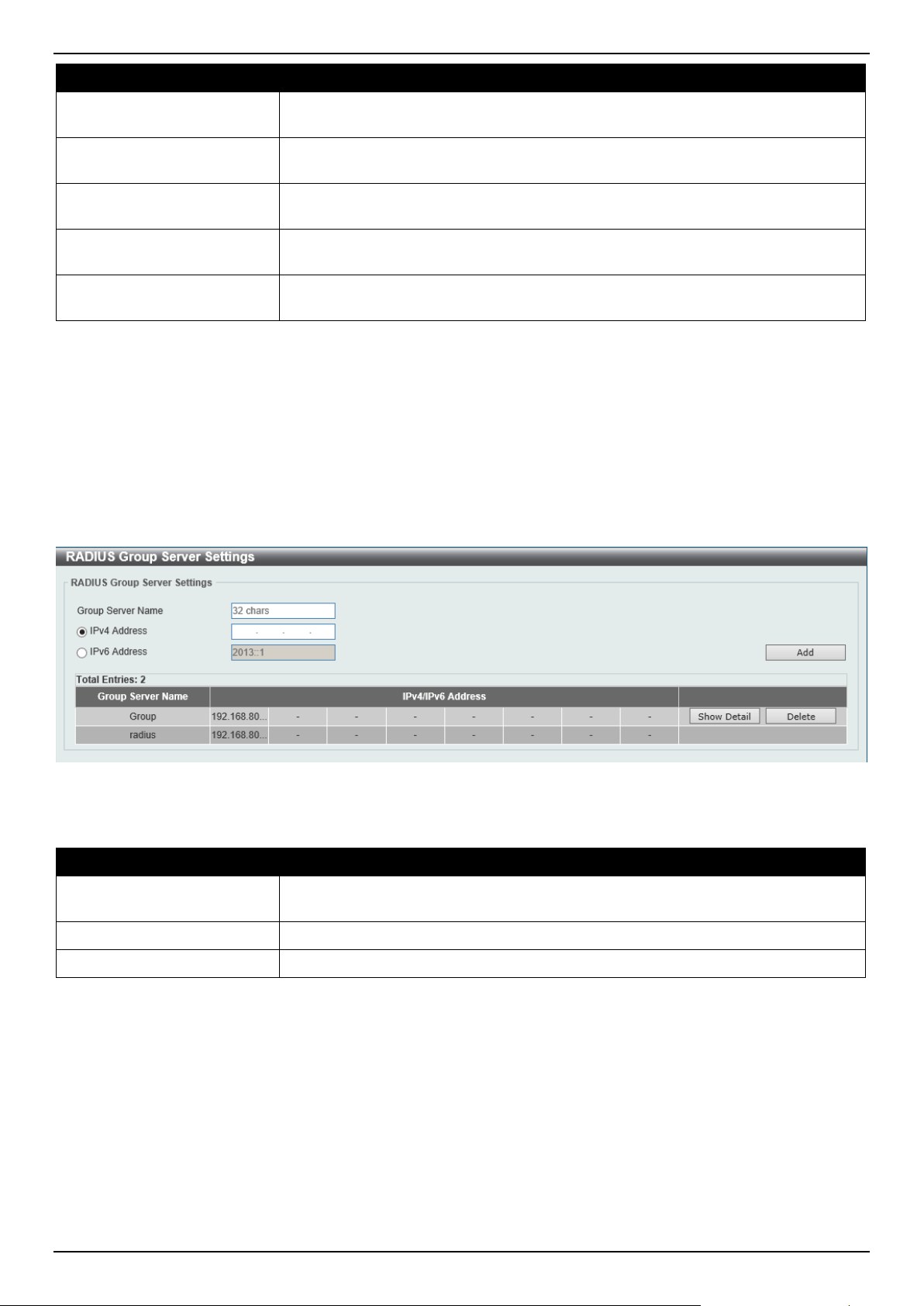
DGS-1520 Series Gigabit Ethernet Smart Managed Switch Web UI Reference Guide
425
Parameter Description
Accounting Port
Enter the accounting port number used here. This value must be between 0 and
65535. By default, this value is 1813. If no accounting is used, use the value 0.
Retransmit
Enter the retransmit value used here. This value must be between 0 and 20. By
default, this value is 3. To disable this option, enter the value 0.
Timeout
Enter the timeout value used here. This value must be between 1 and 255
seconds. By default, this value is 5 seconds.
Key Type Select the key type that will be used here. Options to choose from are Plain Text
and Encrypted.
Key
Enter the key, used to communicate with the RADIUS server, here. This key can
be up to 254 characters long.
Click the Apply button to accept the changes made.
Click the Delete button to remove the specified entry.
RADIUS Group Server Settings
This window is used to display and configure the RADIUS group server settings.
To view the following window, click Security > RADIUS > RADIUS Group Server Settings, as shown below:
Figure 9-32 RADIUS Group Server Settings Window
The fields that can be configured are described below:
Parameter Description
Group Server Name
Enter the RADIUS group server name here. This name can be up to 32 characters
long.
IPv4 Address
Enter the group server IPv4 address here.
IPv6 Address
Enter the group server IPv6 address here.
Click the Add button to add a new entry based on the information entered.
Click the Show Detail button to view and configure detailed settings for the RADIUS group server.
Click the Delete button to remove the specified entry.
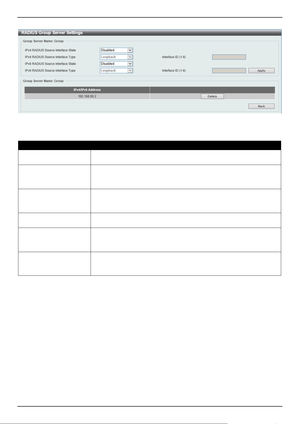
DGS-1520 Series Gigabit Ethernet Smart Managed Switch Web UI Reference Guide
426
After clicking the Show Detail button, the following page will be available.
Figure 9-33 RADIUS Group Server Settings (Detail) Window
The fields that can be configured are described below:
Parameter Description
IPv4 RADIUS Source
Interface State
Select to enable or disable the state of the IPv4 RADIUS source interface here.
IPv4 RADIUS Source
Interface Type
Select the IPv4 RADIUS source interface type here. Options to choose from are:
• Loopback - Specifies the IPv4 RADIUS source interface type as Loopback.
• VLAN - Specifies the IPv4 RADIUS source interface type as VLAN.
Interface ID
Enter the IPv4 RADIUS source interface ID here.
The Loopback interface range is from 1 to 8.
The VLAN interface range is from 1 to 4094.
IPv6 RADIUS Source
Interface State
Select to enable or disable the state of the IPv6 RADIUS source interface here.
IPv6 RADIUS Source
Interface Type
Select the IPv6 RADIUS source interface type here. Options to choose from are:
• Loopback - Specifies the IPv6 RADIUS source interface type as Loopback.
• VLAN - Specifies the IPv6 RADIUS source interface type as VLAN.
Interface ID
Enter the IPv6 RADIUS source interface ID here.
The Loopback interface range is from 1 to 8.
The VLAN interface range is from 1 to 4094.
Click the Apply button to accept the changes made.
Click the Delete button to remove the specified entry.
Click the Back button to return to the previous window.
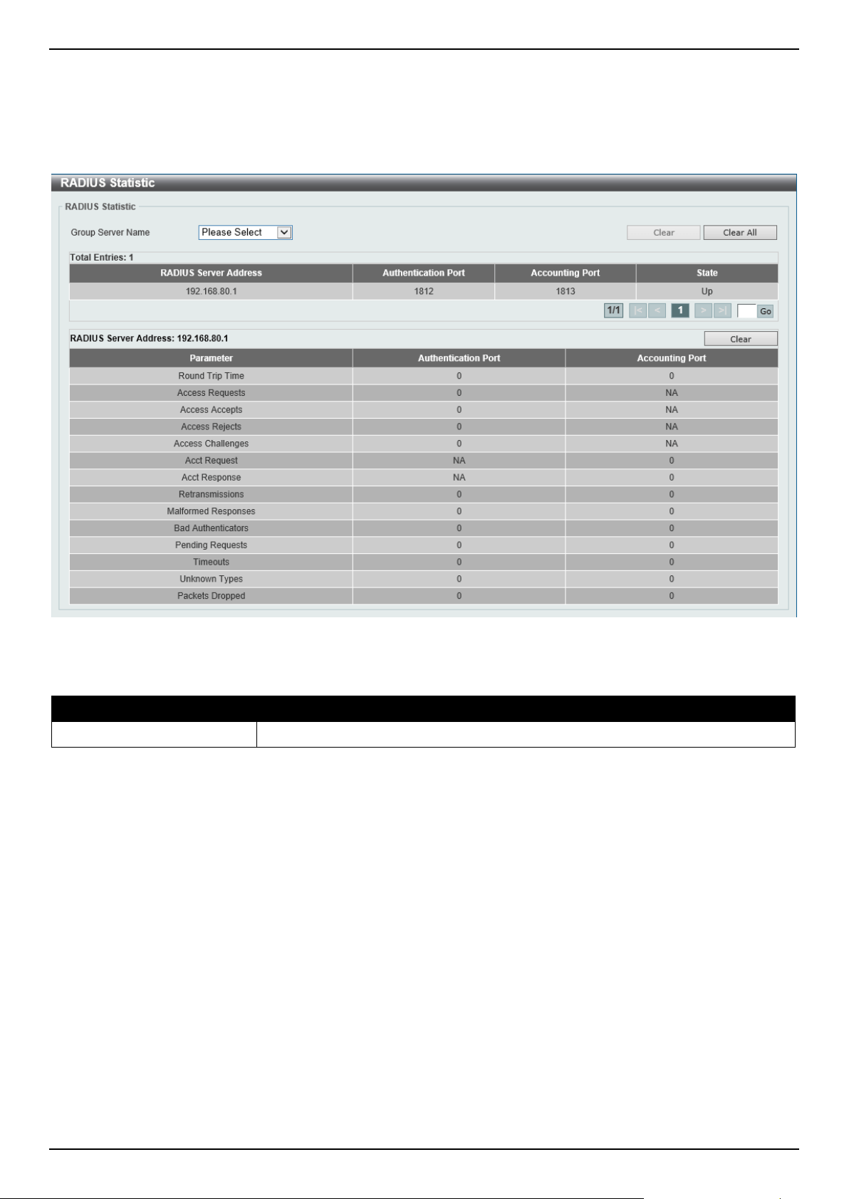
DGS-1520 Series Gigabit Ethernet Smart Managed Switch Web UI Reference Guide
427
RADIUS Statistic
This window is used to view and clear the RADIUS statistics information.
To view the following window, click Security > RADIUS > RADIUS Statistic, as shown below:
Figure 9-34 RADIUS Statistic Window
The fields that can be configured are described below:
Parameter Description
Group Server Name
Select the RADIUS group server name from this list here.
Click the Clear button to clear the information based on the selections made.
Click the Clear All button to clear all the information in this table.
Enter a page number and click the Go button to navigate to a specific page when multiple pages exist.
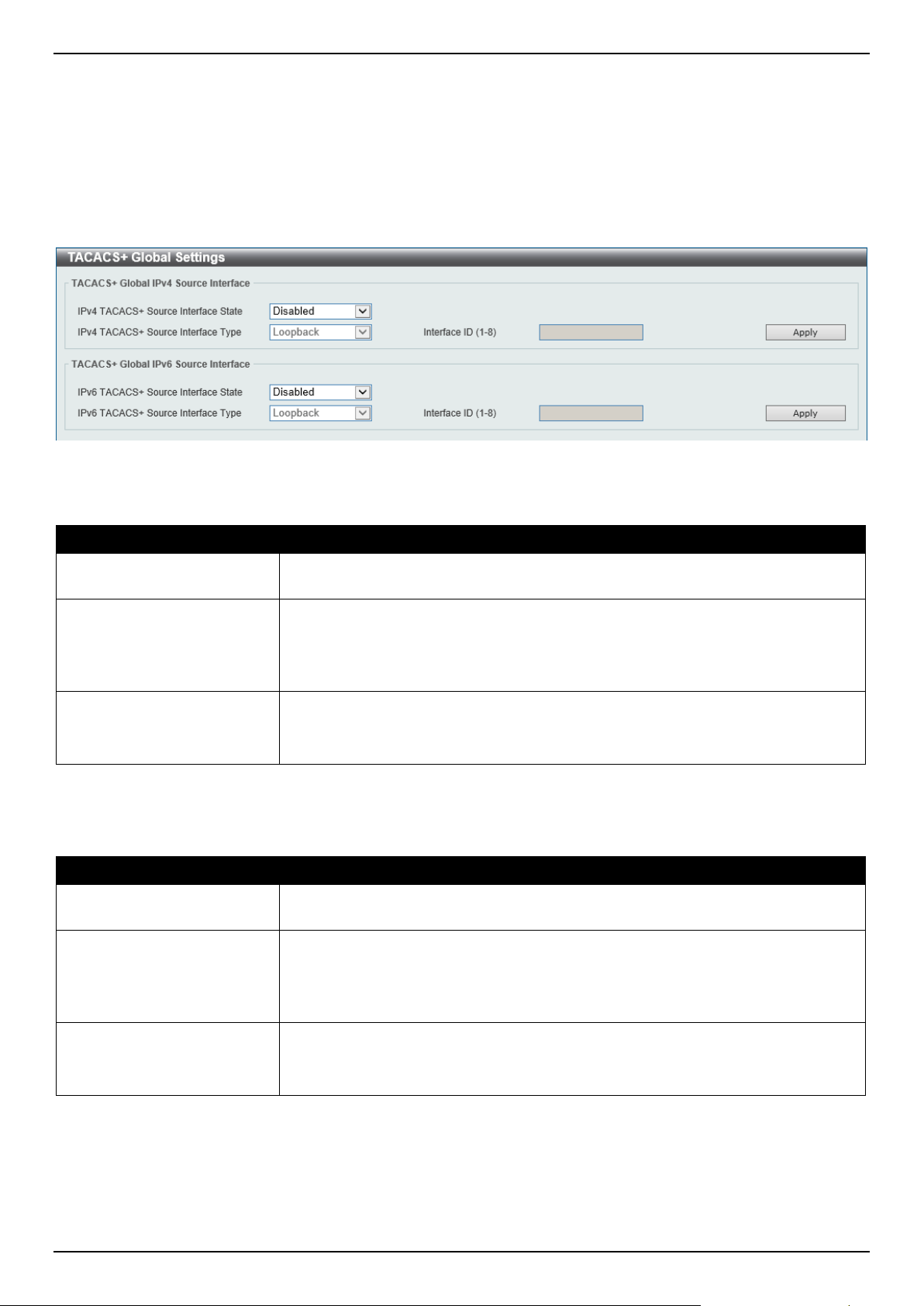
DGS-1520 Series Gigabit Ethernet Smart Managed Switch Web UI Reference Guide
428
TACACS+
TACACS+ Global Settings
This window is used to display and configure the global TACACS+ server settings.
To view the following window, click Security > TACACS+ > TACACS+ Global Settings, as shown below:
Figure 9-35 TACACS+ Global Settings Window
The fields that can be configured in TACACS+ Global IPv4 Source Interface are described below:
Parameter Description
IPv4 TACACS+ Source
Interface State
Select to enable or disable the state of the IPv4 TACACS+ source interface here.
IPv4 TACACS+ Source
Interface Type
Select the IPv4 TACACS+ source interface type here. Options to choose from are:
• Loopback - Specifies the IPv4 TACACS+ source interface type as
Loopback.
• VLAN - Specifies the IPv4 TACACS+ source interface type as VLAN.
Interface ID
Enter the IPv4 TACACS+ source interface ID here.
The Loopback interface range is from 1 to 8.
The VLAN interface range is from 1 to 4094.
Click the Apply button to accept the changes made.
The fields that can be configured in TACACS+ Global IPv6 Source Interface are described below:
Parameter Description
IPv6 TACACS+ Source
Interface State
Select to enable or disable the state of the IPv6 TACACS+ source interface here.
IPv6 TACACS+ Source
Interface Type
Select the IPv6 TACACS+ source interface type here. Options to choose from are:
• Loopback - Specifies the IPv6 TACACS+ source interface type as
Loopback.
• VLAN - Specifies the IPv6 TACACS+ source interface type as VLAN.
Interface ID
Enter the IPv6 TACACS+ source interface ID here.
The Loopback interface range is from 1 to 8.
The VLAN interface range is from 1 to 4094.
Click the Apply button to accept the changes made.
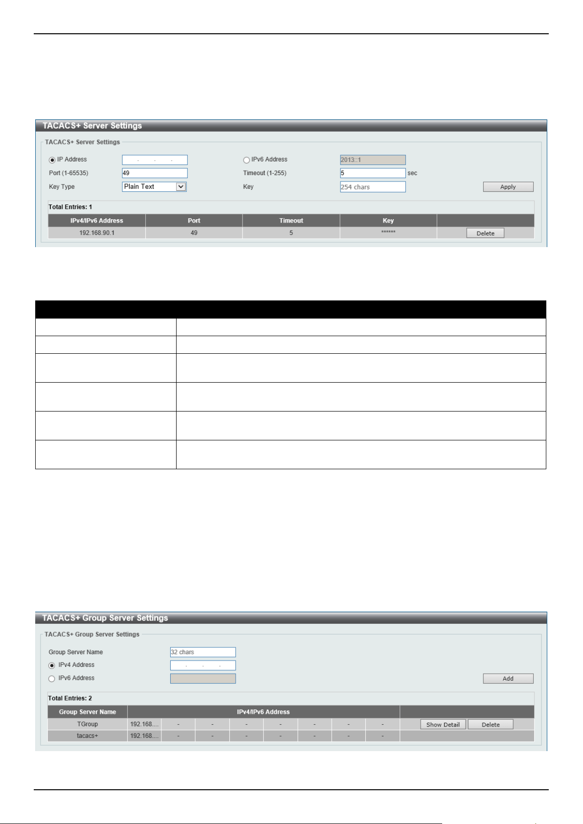
DGS-1520 Series Gigabit Ethernet Smart Managed Switch Web UI Reference Guide
429
TACACS+ Server Settings
This window is used to display and configure the TACACS+ server settings.
To view the following window, click Security > TACACS+ > TACACS+ Server Settings, as shown below:
Figure 9-36 TACACS+ Server Settings Window
The fields that can be configured are described below:
Parameter Description
IP Address
Enter the TACACS+ server IPv4 address here.
IPv6 Address
Enter the TACACS+ server IPv6 address here.
Port
Enter the port number used here. This value must be between 1 and 65535. By
default, this value is 49.
Timeout
Enter the timeout value here. This value must be between 1 and 255 seconds. By
default, this value is 5 seconds.
Key Type Select the key type that will be used here. Options to choose from are Plain Text
and Encrypted.
Key
Enter the key, used to communicate with the TACACS+ server, here. This key can
be up to 254 characters long.
Click the Apply button to accept the changes made.
Click the Delete button to remove the specified entry.
TACACS+ Group Server Settings
This window is used to display and configure the TACACS+ group server settings.
To view the following window, click Security > TACACS+ > TACACS+ Group Server Settings, as shown below:
Figure 9-37 TACACS+ Group Server Settings Window
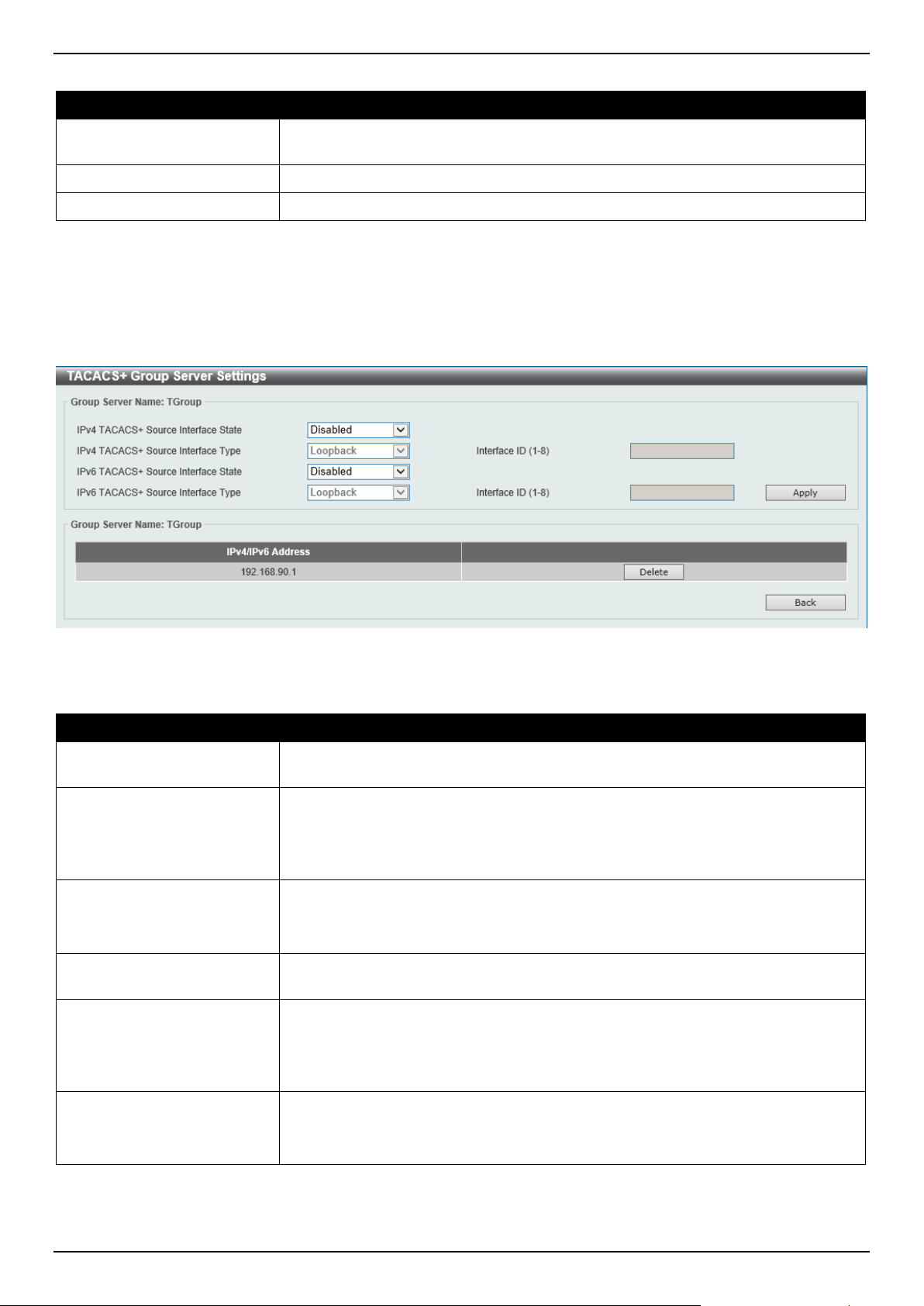
DGS-1520 Series Gigabit Ethernet Smart Managed Switch Web UI Reference Guide
430
The fields that can be configured are described below:
Parameter Description
Group Server Name
Enter the TACACS+ group server name here. This name can be up to 32
characters long.
IPv4 Address
Enter the IPv4 address of the TACACS+ group server here.
IPv6 Address
Enter the IPv6 address of the TACACS+ group server here.
Click the Add button to add a new entry based on the information entered.
Click the Show Detail button to view and configure detailed settings for the TACACS+ group server.
Click the Delete button to remove the specified entry.
After clicking the Show Detail button, the following page will be available.
Figure 9-38 TACACS+ Group Server Settings (Show Detail) Window
The fields that can be configured are described below:
Parameter Description
IPv4 TACACS+ Source
Interface State
Select to enable or disable the state of the IPv4 TACACS+ source interface here.
IPv4 TACACS+ Source
Interface Type
Select the IPv4 TACACS+ source interface type here. Options to choose from are:
• Loopback - Specifies the IPv4 TACACS+ source interface type as
Loopback.
• VLAN - Specifies the IPv4 TACACS+ source interface type as VLAN.
Interface ID
Enter the IPv4 TACACS+ source interface ID here.
The Loopback interface range is from 1 to 8.
The VLAN interface range is from 1 to 4094.
IPv6 TACACS+ Source
Interface State
Select to enable or disable the state of the IPv6 TACACS+ source interface here.
IPv6 TACACS+ Source
Interface Type
Select the IPv6 TACACS+ source interface type here. Options to choose from are:
• Loopback - Specifies the IPv6 TACACS+ source interface type as
Loopback.
• VLAN - Specifies the IPv6 TACACS+ source interface type as VLAN.
Interface ID
Enter the IPv6 TACACS+ source interface ID here.
The Loopback interface range is from 1 to 8.
The VLAN interface range is from 1 to 4094.
Click the Apply button to accept the changes made.
Click the Delete button to remove the specified entry.
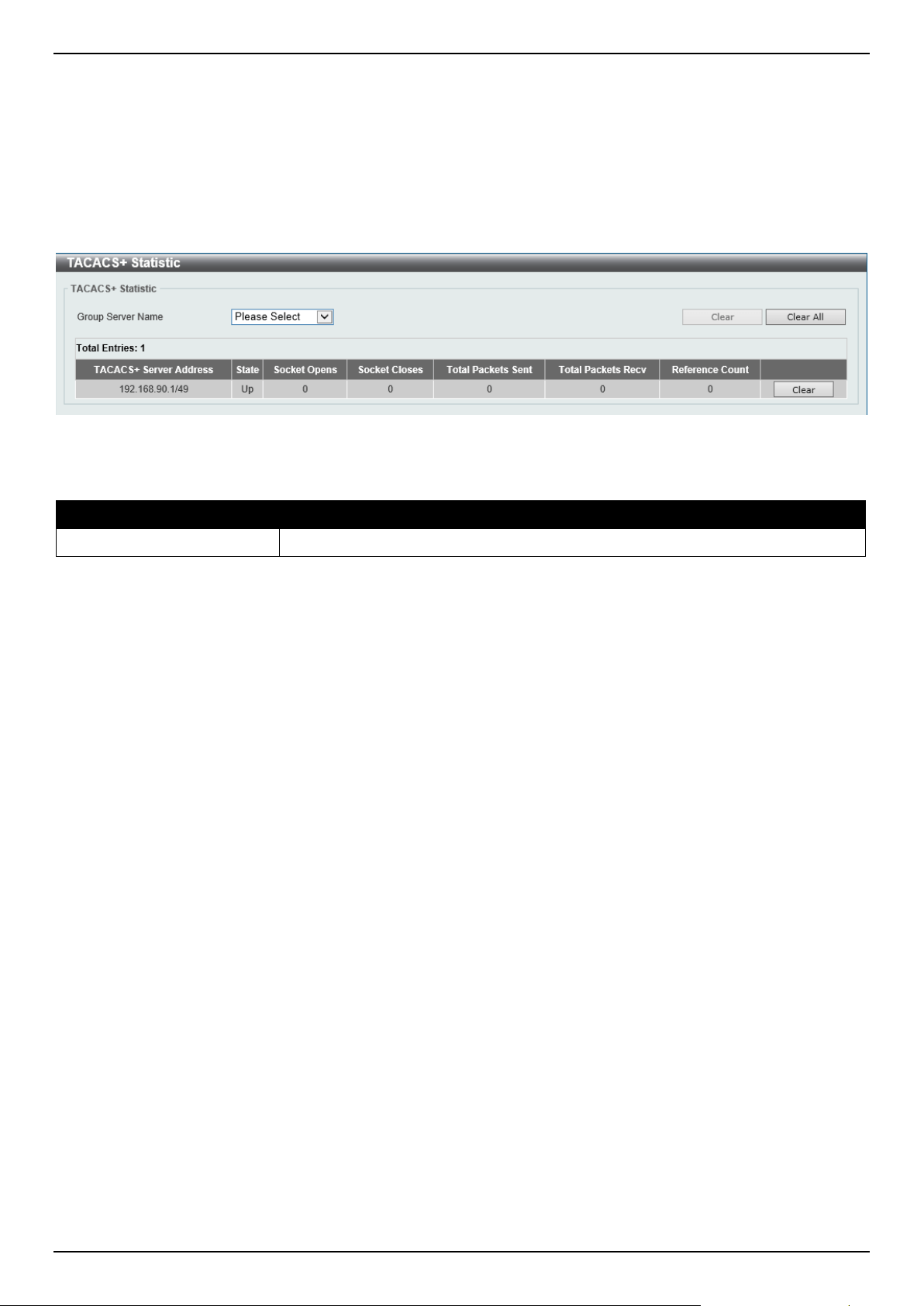
DGS-1520 Series Gigabit Ethernet Smart Managed Switch Web UI Reference Guide
431
Click the Back button to return to the previous window.
TACACS+ Statistic
This window is used to view and clear the TACACS+ statistic information.
To view the following window, click Security > TACACS+ > TACACS+ Statistic, as shown below:
Figure 9-39 TACACS+ Statistic Window
The fields that can be configured are described below:
Parameter Description
Group Server Name
Select the TACACS+ group server name from this list here.
Click the first Clear button to clear the information based on the group selected.
Click the Clear All button to clear all the information in this table.
Click the second Clear button to clear all the information for the specific entry.
IMPB
The IP network layer uses a four-byte address. The Ethernet link-layer uses a six-byte MAC address. Binding these
two address types together allows the transmission of data between the layers. The primary purpose of IP-MAC-Port
Binding (IMPB) is to restrict the access to a Switch to a number of authorized users. Authorized clients can access a
Switch's port by either checking the pair of IP-MAC addresses with the pre-configured database or if DHCP snooping
has been enabled in which case the Switch will automatically learn the IP/MAC pairs by snooping DHCP packets and
saving them to the IMPB white list. If an unauthorized user tries to access an IP-MAC binding enabled port, the
system will block the access by dropping its packet. Active and inactive entries use the same database. The function
is port-based, meaning a user can enable or disable the function on the individual port.
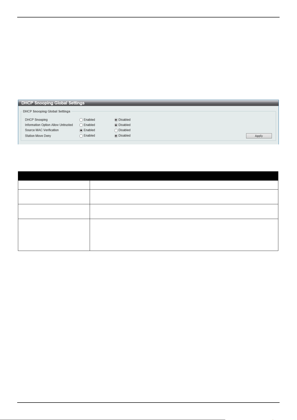
DGS-1520 Series Gigabit Ethernet Smart Managed Switch Web UI Reference Guide
432
IPv4
DHCPv4 Snooping
DHCP Snooping Global Settings
This window is used to display and configure the global DHCP snooping settings.
To view the following window, click Security > IMPB > IPv4 > DHCPv4 Snooping > DHCP Snooping Global
Settings, as shown below:
Figure 9-40 DHCP Snooping Global Settings Window
The fields that can be configured are described below:
Parameter Description
DHCP Snooping
Select to enable or disable the global DHCP snooping status.
Information Option Allow
Untrusted
Select to enable or disable the option to globally allow DHCP packets with the
relay Option 82 on the untrusted interface.
Source MAC Verification
Select to enable or disable the verification that the source MAC address in a
DHCP packet matches the client hardware address.
Station Move Deny
Select to enable or disable the DHCP snooping station move state. When DHCP
snooping station move is enabled, the dynamic DHCP snooping binding entry with
the same VLAN ID and MAC address on the specific port can move to another port
if it detects that a new DHCP process belong to the same VLAN ID and MAC
address.
Click the Apply button to accept the changes made.
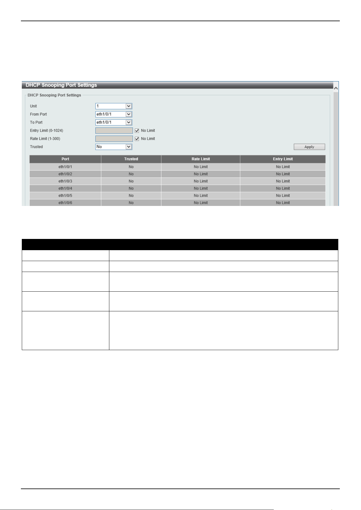
DGS-1520 Series Gigabit Ethernet Smart Managed Switch Web UI Reference Guide
433
DHCP Snooping Port Settings
This window is used to display and configure the DHCP snooping port settings.
To view the following window, click Security > IMPB > IPv4 > DHCPv4 Snooping > DHCP Snooping Port Settings,
as shown below:
Figure 9-41 DHCP Snooping Port Settings Window
The fields that can be configured are described below:
Parameter Description
Unit
Select the Switch unit that will be used for this configuration here.
From Port - To Port
Select the appropriate port range used for the configuration here.
Entry Limit
Enter the entry limit value here. This value must be between 0 and 1024.
Tick the No Limit option to disable the function.
Rate Limit
Enter the rate limit value here. This value must be between 1 and 300.
Tick the No Limit option to disable the function.
Trusted Select the trusted option here. Options to choose from are No and Yes. Ports
connected to the DHCP server or to other Switches should be configured as
trusted interfaces. The ports connected to DHCP clients should be configured as
untrusted interfaces. DHCP snooping acts as a firewall between untrusted
interfaces and DHCP servers.
Click the Apply button to accept the changes made.
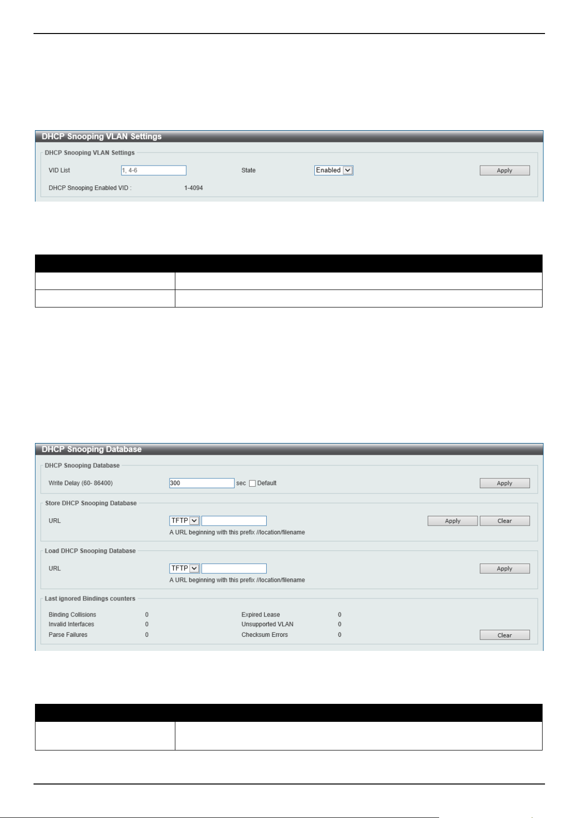
DGS-1520 Series Gigabit Ethernet Smart Managed Switch Web UI Reference Guide
434
DHCP Snooping VLAN Settings
This window is used to display and configure the DHCP snooping VLAN settings.
To view the following window, click Security > IMPB > IPv4 > DHCPv4 Snooping > DHCP Snooping VLAN
Settings, as shown below:
Figure 9-42 DHCP Snooping VLAN Settings Window
The fields that can be configured are described below:
Parameter Description
VID List
Enter the VLAN ID list used here.
State
Select to enable or disable the DHCP snooping VLAN setting here.
Click the Apply button to accept the changes made.
DHCP Snooping Database
This window is used to display and configure the DHCP snooping database settings.
To view the following window, click Security > IMPB > IPv4 > DHCPv4 Snooping > DHCP Snooping Database, as
shown below:
Figure 9-43 DHCP Snooping Database Window
The fields that can be configured in DHCP Snooping Database are described below:
Parameter Description
Write Delay
Enter the write delay time value here. This value must be between 60 and 86400
seconds. By default, this value is 300 seconds.
Click the Apply button to accept the changes made.
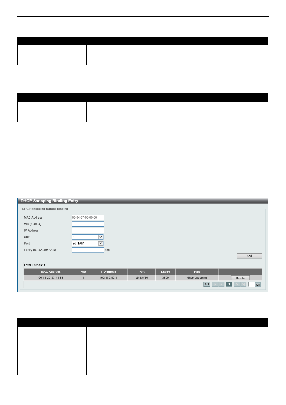
DGS-1520 Series Gigabit Ethernet Smart Managed Switch Web UI Reference Guide
435
The fields that can be configured in Store DHCP Snooping Database are described below:
Parameter Description
URL
Select the location from the drop-down list and enter the URL where the DHCP
snooping database will be stored to here. Only TFTP is available for selection. An
example URL is given.
Click the Apply button to accept the changes made.
The fields that can be configured in Load DHCP Snooping Database are described below:
Parameter Description
URL
Select the location from the drop-down list and enter the URL where the DHCP
snooping database will be loaded from here. Only TFTP is available for selection.
An example URL is given.
Click the Apply button to accept the changes made.
Click the Clear button to clear all the counter information.
DHCP Snooping Binding Entry
This window is used to display and configure the DHCP snooping binding entries.
To view the following window, click Security > IMPB > IPv4 > DHCPv4 Snooping > DHCP Snooping Binding
Entry, as shown below:
Figure 9-44 DHCP Snooping Binding Entry Window
The fields that can be configured are described below:
Parameter Description
MAC Address
Enter the MAC address of the DHCP snooping binding entry here.
VID
Enter the VLAN ID of the DHCP snooping binding entry here. This value must be
between 1 and 4094.
IP Address
Enter the IP address of the DHCP snooping binding entry here.
Unit
Select the Switch unit that will be used for this configuration here.
Port
Select the appropriate port used for the configuration here.
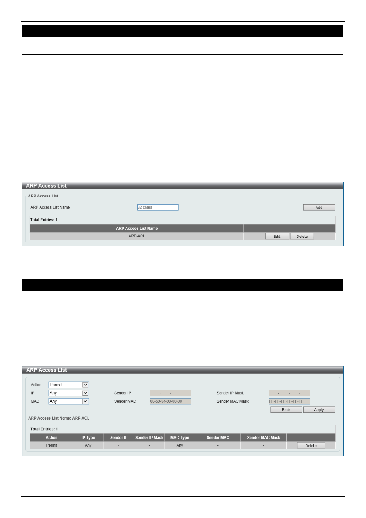
DGS-1520 Series Gigabit Ethernet Smart Managed Switch Web UI Reference Guide
436
Parameter Description
Expiry
Enter the expiry time value used here. This value must be between 60 and
4294967295 seconds.
Click the Add button to add a new entry based on the information entered.
Click the Delete button to remove the specified entry.
Enter a page number and click the Go button to navigate to a specific page when multiple pages exist.
Dynamic ARP Inspection
ARP Access List
This window is used to display and configure the dynamic ARP inspection settings.
To view the following window, click Security > IMPB > IPv4 > Dynamic ARP Inspection > ARP Access List, as
shown below:
Figure 9-45 ARP Access List Window
The fields that can be configured are described below:
Parameter Description
ARP Access List Name
Enter the ARP access list name used here. This name can be up to 32 characters
long.
Click the Add button to add a new entry based on the information entered.
Click the Edit button to re-configure the specific entry.
Click the Delete button to remove the specified entry.
After clicking the Edit button, the following window will appear.
Figure 9-46 ARP Access List (Edit) Window
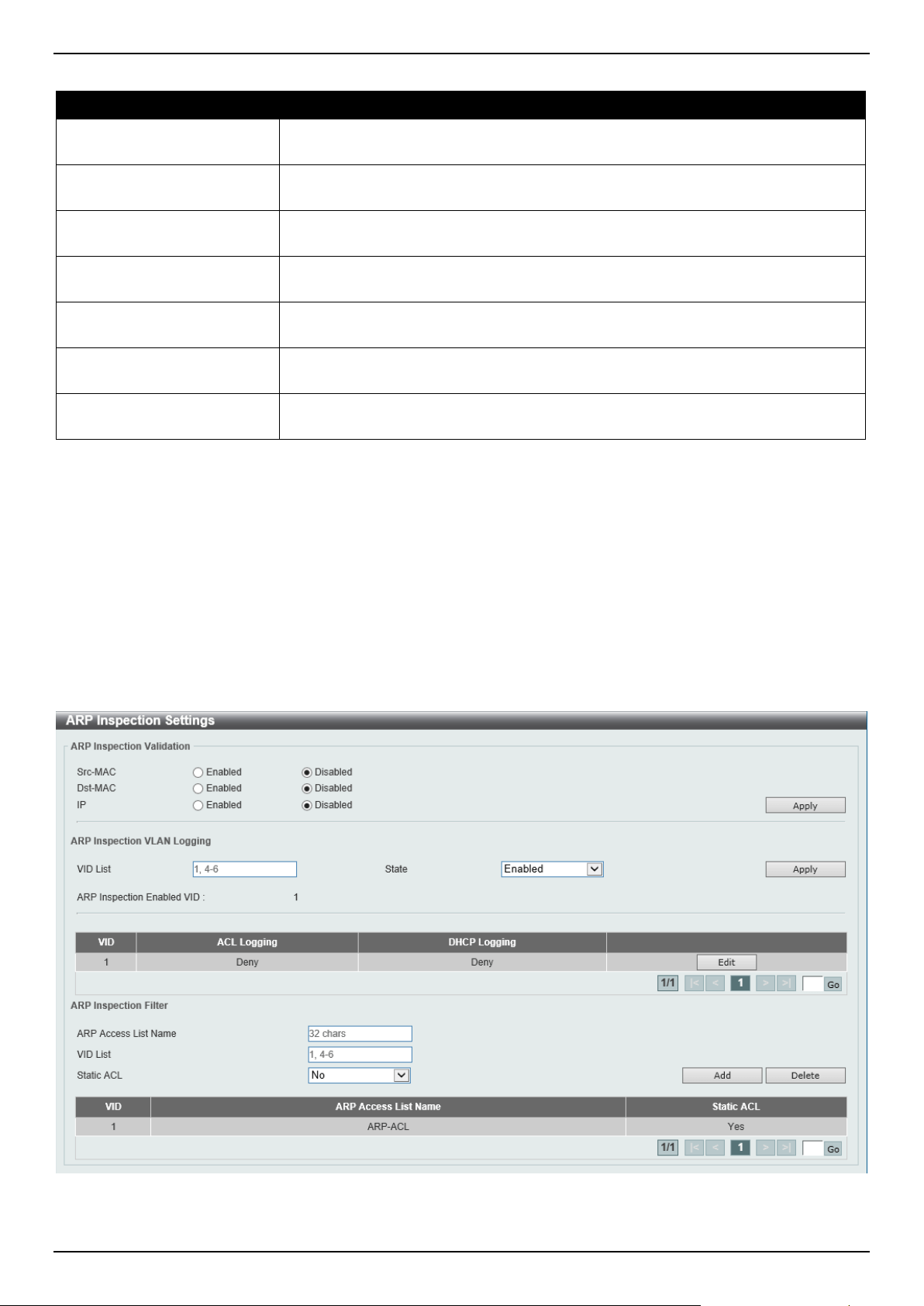
DGS-1520 Series Gigabit Ethernet Smart Managed Switch Web UI Reference Guide
437
The fields that can be configured are described below:
Parameter Description
Action Select the action that will be taken here. Options to choose from are Permit and
Deny.
IP
Select the type of sender IP address that will be used here. Options to choose
from are Any, Host, and IP with Mask.
Sender IP After selecting the Host or IP with Mask options as the type of IP, enter the
sender IP address used here.
Sender IP Mask After selecting the IP with Mask option as the type of IP, enter the sender IP mask
used here.
MAC
Select the type of sender MAC address that will be used here. Options to choose
from are Any, Host, and MAC with Mask.
Sender MAC After selecting the Host or MAC with Mask options as the type of MAC, enter the
sender MAC address used here.
Sender MAC Mask After selecting the MAC with Mask option as the type of MAC, enter the sender
MAC mask used here.
Click the Back button to return to the previous page.
Click the Apply button to accept the changes made.
Click the Delete button to remove the specified entry.
ARP Inspection Settings
This window is used to display and configure the ARP inspection settings.
To view the following window, click Security > IMPB > IPv4 > Dynamic ARP Inspection > ARP Inspection
Settings, as shown below:
Figure 9-47 ARP Inspection Settings Window

DGS-1520 Series Gigabit Ethernet Smart Managed Switch Web UI Reference Guide
438
The fields that can be configured in ARP Inspection Validation are described below:
Parameter Description
Src-MAC
Select to enable or disable the source MAC option here. This option specifies to
check for ARP requests and response packets and the consistency of the source
MAC address in the Ethernet header against the sender MAC address in the ARP
payload.
Dst-MAC
Select to enable or disable the destination MAC option here. This option specifies
to check for ARP response packets and the consistency of the destination MAC
address in the Ethernet header against the target MAC address in the ARP
payload.
IP
Select to enable or disable the IP option here. This option specifies to check the
ARP body for invalid and unexpected IP addresses. It also specifies to check the
validity of IP address in the ARP payload. The sender IP in both the ARP request
and response and target IP in the ARP response are validated. Packets destined
for the IP addresses 0.0.0.0, 255.255.255.255, and all IP multicast addresses are
dropped. Sender IP addresses are checked in all ARP requests and responses,
and target IP addresses are checked only in ARP responses.
Click the Apply button to accept the changes made.
The fields that can be configured in ARP Inspection VLAN Logging are described below:
Parameter Description
VID List
Enter the ARP inspection VLAN ID list/range here.
State
Select the enable or disable the ARP inspection VLAN logging function here.
ACL Logging After clicking the Edit button, select the ACL logging action here. Options to
choose from are Deny, Permit, All, and None.
DHCP Logging After clicking the Edit button, select the DHCP logging action here. Options to
choose from are Deny, Permit, All, and None.
Click the Apply button to accept the changes made.
Click the Edit button to configure the ACL/DHCP logging actions.
Enter a page number and click the Go button to navigate to a specific page when multiple pages exist.
The fields that can be configured in ARP Inspection Filter are described below:
Parameter Description
ARP Access List Name
Enter the ARP access list name used here. This name can be up to 32 characters
long.
VID List
Enter the VLAN ID list used here.
Static ACL Select whether to use a static ACL or not here by either selecting Yes or No.
Click the Add button to add a new entry based on the information entered.
Click the Delete button to remove an entry based on the information entered.
Enter a page number and click the Go button to navigate to a specific page when multiple pages exist.
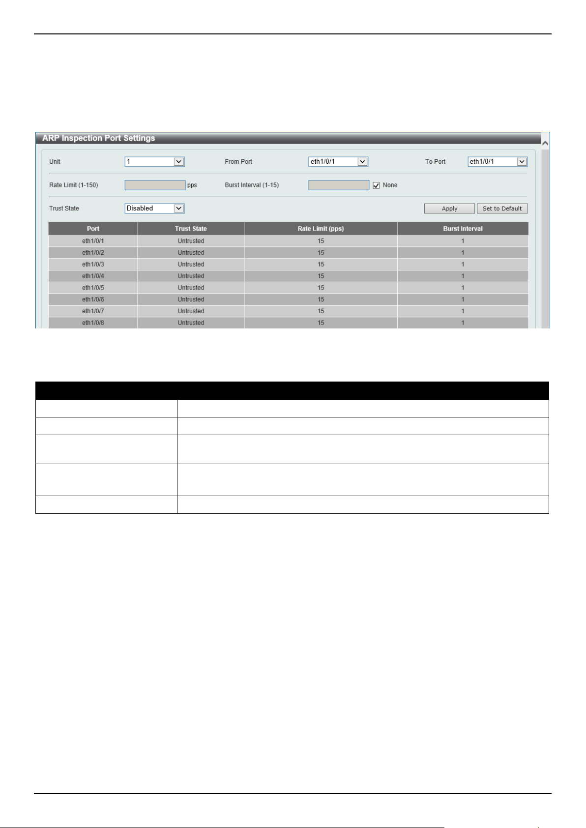
DGS-1520 Series Gigabit Ethernet Smart Managed Switch Web UI Reference Guide
439
ARP Inspection Port Settings
This window is used to display and configure the ARP inspection port settings.
To view the following window, click Security > IMPB > IPv4 > Dynamic ARP Inspection > ARP Inspection Port
Settings, as shown below:
Figure 9-48 ARP Inspection Port Settings Window
The fields that can be configured are described below:
Parameter Description
Unit
Select the Switch unit that will be used for this configuration here.
From Port - To Port
Select the appropriate port range used for the configuration here.
Rate Limit
Enter the rate limit value here. This value must be between 1 and 150 packets per
seconds.
Burst Interval
Enter the burst interval value here. This value must be between 1 and 15.
Tick the None option to disable the option.
Trust State
Select to enable or disable the trust state here.
Click the Apply button to accept the changes made.
Click the Set to Default button to change the information to the default values.
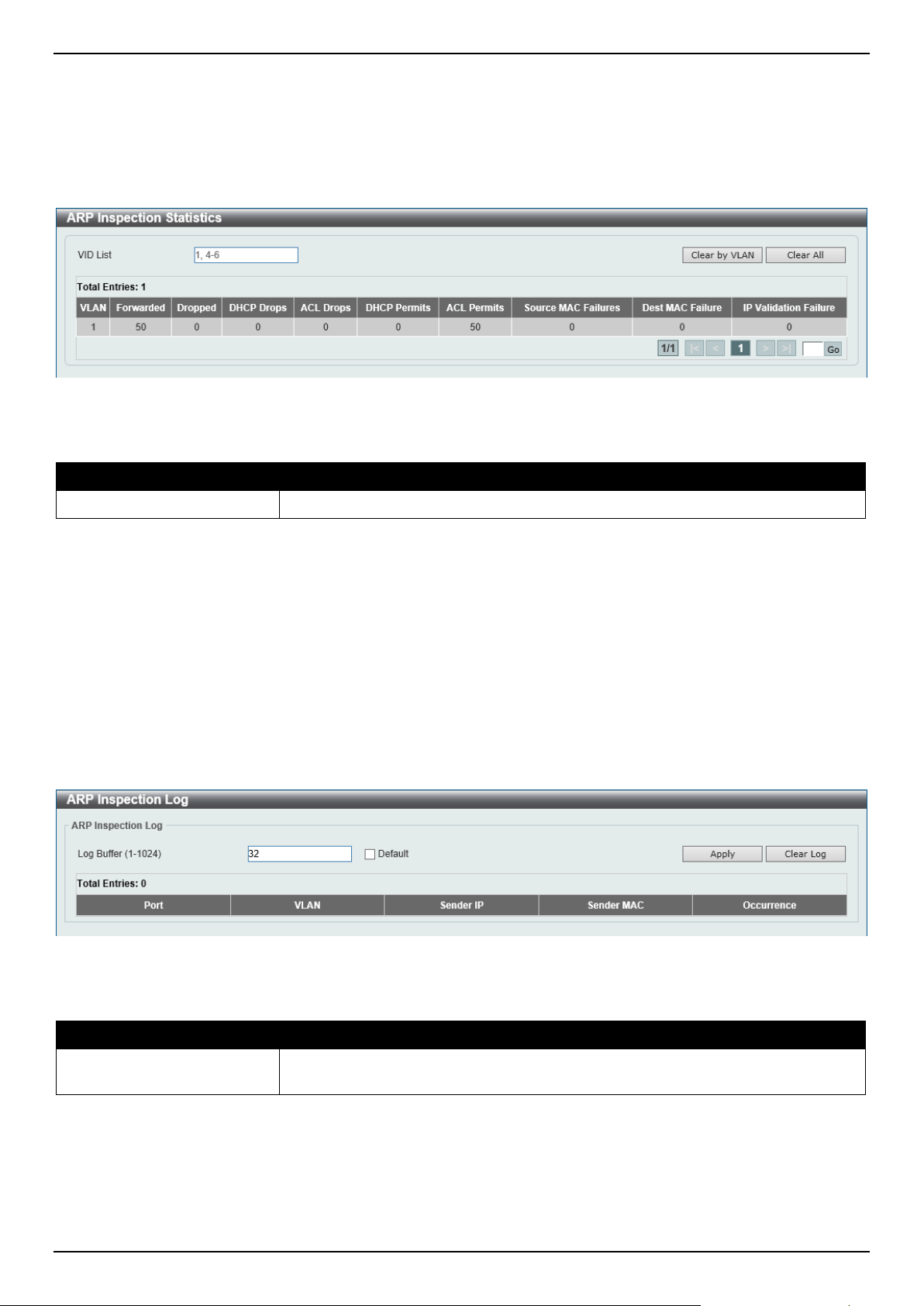
DGS-1520 Series Gigabit Ethernet Smart Managed Switch Web UI Reference Guide
440
ARP Inspection Statistics
This window is used to view and clear the ARP inspection statistics information.
To view the following window, click Security > IMPB > IPv4 > Dynamic ARP Inspection > ARP Inspection
Statistics, as shown below:
Figure 9-49 ARP Inspection Statistics Window
The fields that can be configured are described below:
Parameter Description
VID List
Enter the VLAN ID list used here.
Click the Clear by VLAN button to clear the information based on the VLAN ID(s) entered.
Click the Clear All button to clear all the information in this table.
Enter a page number and click the Go button to navigate to a specific page when multiple pages exist.
ARP Inspection Log
This window is used to view, configure, and clear the ARP inspection log information.
To view the following window, click Security > IMPB > IPv4 > Dynamic ARP Inspection > ARP Inspection Log, as
shown below:
Figure 9-50 ARP Inspection Log Window
The fields that can be configured are described below:
Parameter Description
Log Buffer
Enter the log buffer value used here. This value must be between 1 and 1024. By
default, this value is 32.
Click the Apply button to accept the changes made.
Click the Clear Log button to clear the log.
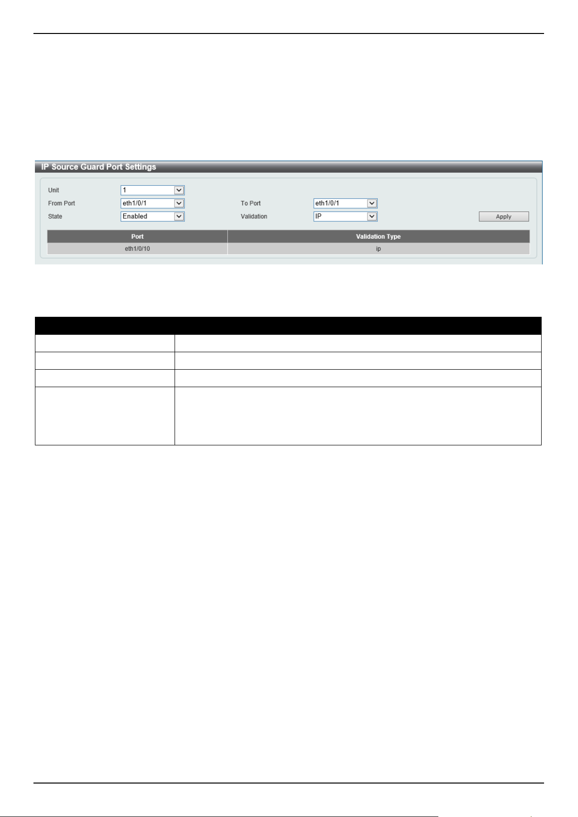
DGS-1520 Series Gigabit Ethernet Smart Managed Switch Web UI Reference Guide
441
IP Source Guard
IP Source Guard Port Settings
This window is used to display and configure the IP Source Guard (IPSG) port settings.
To view the following window, click Security > IMPB > IPv4 > IP Source Guard > IP Source Guard Port Settings,
as shown below:
Figure 9-51 IP Source Guard Port Settings Window
The fields that can be configured are described below:
Parameter Description
Unit
Select the Switch unit that will be used for this configuration here.
From Port - To Port
Select the appropriate port range used for the configuration here.
State
Select to enable or disable the IPSG's state for the specified port(s) here.
Validation
Select the validation method used here. Options to choose from are:
• IP - Specifies that the IP address of the received packets will be checked.
• IP-MAC - Specifies that the IP address and the MAC address of the
received packets will be checked.
Click the Apply button to accept the changes made.
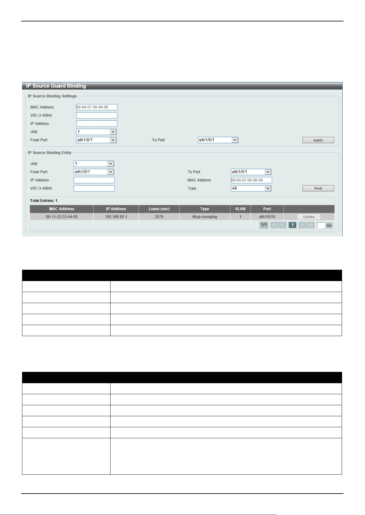
DGS-1520 Series Gigabit Ethernet Smart Managed Switch Web UI Reference Guide
442
IP Source Guard Binding
This window is used to display and configure the IPSG binding settings.
To view the following window, click Security > IMPB > IPv4 > IP Source Guard > IP Source Guard Binding, as
shown below:
Figure 9-52 IP Source Guard Binding Window
The fields that can be configured in IP Source Binding Settings are described below:
Parameter Description
MAC Address
Enter the MAC address of the binding entry here.
VID
Enter the VLAN ID of the binding entry here.
IP Address
Enter the IP address of the binding entry here.
Unit
Select the Switch unit that will be used for this configuration here.
From Port - To Port
Select the appropriate port range used for the configuration here.
Click the Apply button to accept the changes made.
The fields that can be configured in IP Source Binding Entry are described below:
Parameter Description
Unit
Select the Switch unit that will be used for this query here.
From Port - To Port
Select the appropriate port range used for the query here.
IP Address
Enter the IP address of the binding entry here.
MAC Address
Enter the MAC address of the binding entry here.
VID
Enter the VLAN ID of the binding entry here.
Type
Select the type of binding entry to find here. Options to choose from are:
• All - Specifies that all the DHCP binding entries will be displayed.
• DHCP Snooping - Specifies to display the IP-source guard binding entry
learned by DHCP binding snooping.
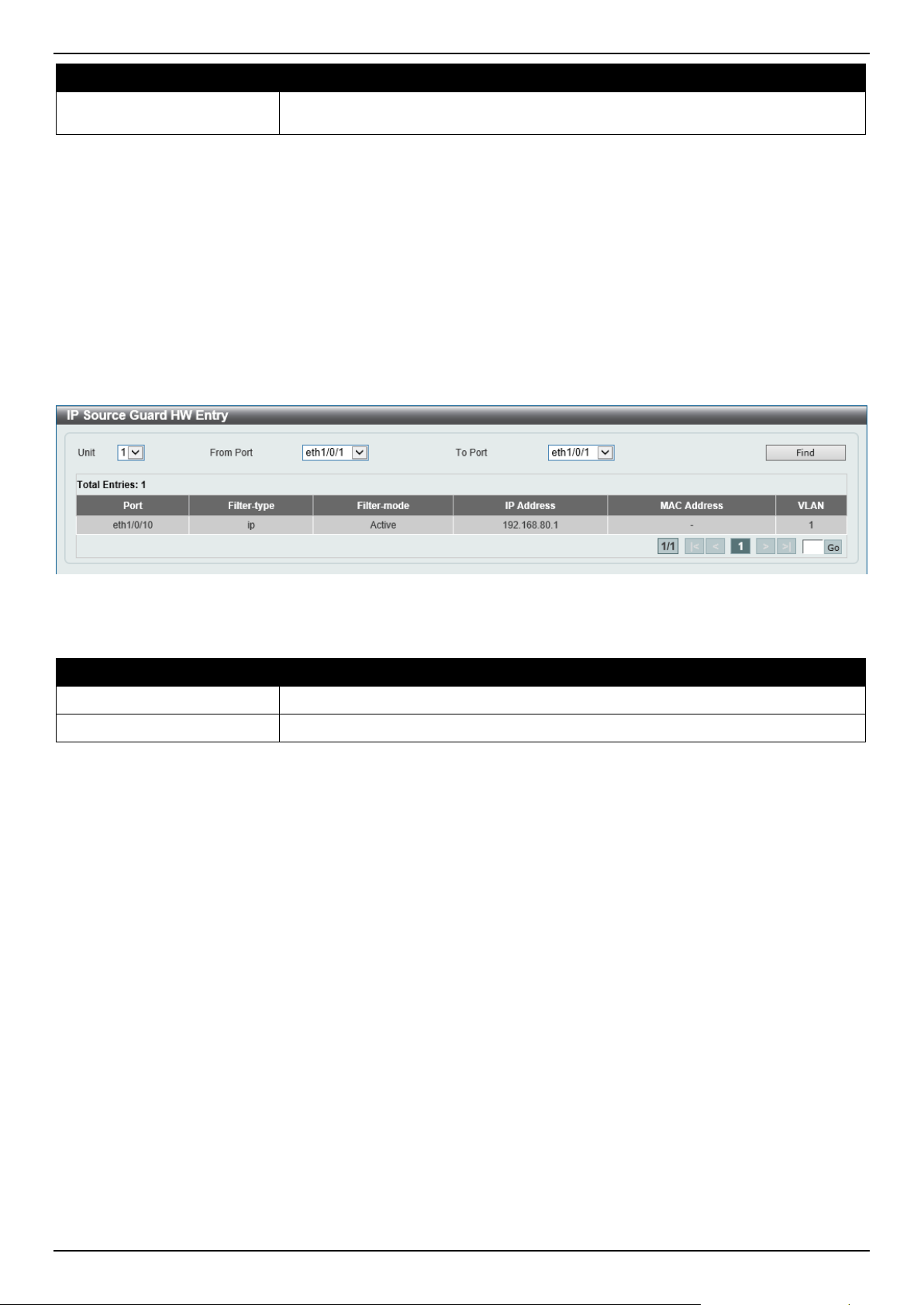
DGS-1520 Series Gigabit Ethernet Smart Managed Switch Web UI Reference Guide
443
Parameter Description
• Static - Specifies to display the IP-source guard binding entry that is
manually configured.
Click the Find button to locate a specific entry based on the information entered.
Click the Delete button to remove the specified entry.
Enter a page number and click the Go button to navigate to a specific page when multiple pages exist.
IP Source Guard HW Entry
This window is used to view the IPSG hardware entries.
To view the following window, click Security > IMPB > IPv4 > IP Source Guard > IP Source Guard HW Entry, as
shown below:
Figure 9-53 IP Source Guard HW Entry Window
The fields that can be configured are described below:
Parameter Description
Unit
Select the Switch unit that will be used for this query here.
From Port - To Port
Select the appropriate port range used for the query here.
Click the Find button to locate a specific entry based on the information entered.
Enter a page number and click the Go button to navigate to a specific page when multiple pages exist.
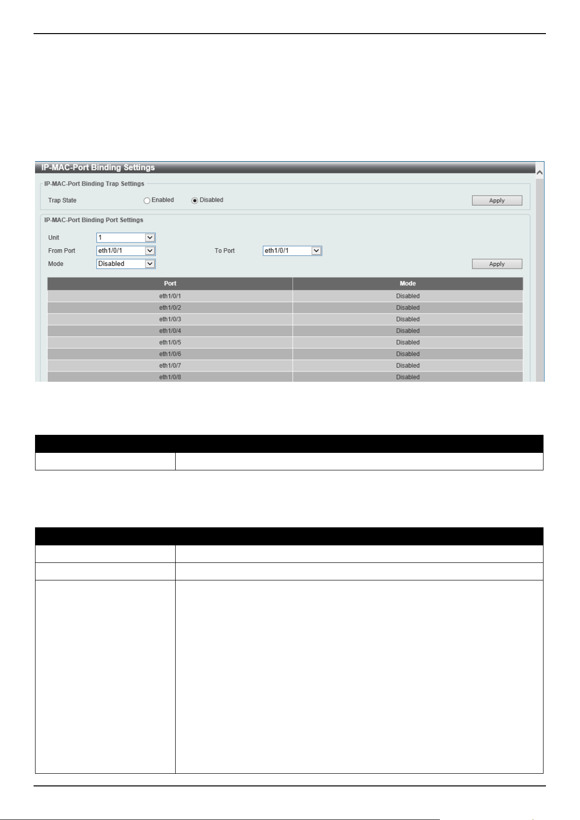
DGS-1520 Series Gigabit Ethernet Smart Managed Switch Web UI Reference Guide
444
Advanced Settings
IP-MAC-Port Binding Settings
This window is used to display and configure the IP-MAC-Port binding settings.
To view the following window, click Security > IMPB > IPv4 > Advanced Settings > IP-MAC-Port Binding Settings,
as shown below:
Figure 9-54 IP-MAC-Port Binding Settings Window
The fields that can be configured in IP-MAC-Port Binding Trap Settings are described below:
Parameter Description
Trap State
Select the enable or disable the IP-MAC-Port binding option's trap state.
Click the Apply button to accept the changes made.
The fields that can be configured in IP-MAC-Port Binding Port Settings are described below:
Parameter Description
Unit
Select the Switch unit that will be used for this configuration here.
From Port - To Port
Select the appropriate port range used for the configuration here.
Mode
Select the mode of access control that will be used here. Options to choose from
are:
• Disabled - Specifies that IP-MAC-Port binding function is disabled on the
specified port(s).
• Strict - When a port is enabled for IMPB strict-mode access control, a host
can only access the port after the host sends ARP or IP packets and the
ARP packet or IP packet sent by the host passes the binding check. To
pass the binding check, the source IP address, source MAC address, VLAN
ID, and arrival port number must match any of the entries defined by either
the IPSG static binding entry or the DHCP snooping learned dynamic
binding entry.
• Loose - When a port is enabled for IMPB loose-mode access control, a host
will be denied to access the port after the host sends ARP or IP packets and
the ARP packet or IP packet sent by the host does not pass the binding
check. To pass the binding check, the source IP address, source MAC
address, VLAN ID, and arrival port must match any of the entries defined by
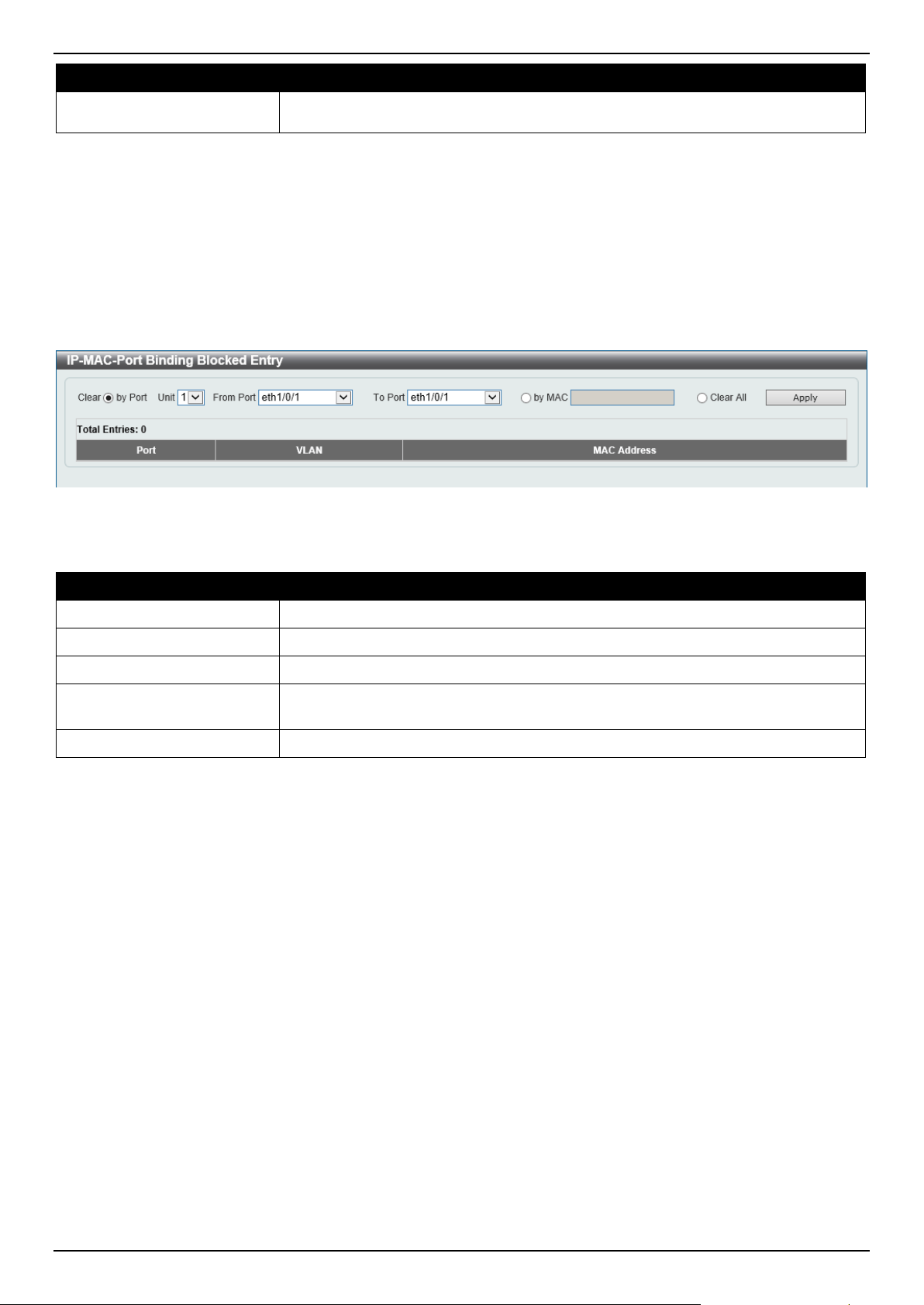
DGS-1520 Series Gigabit Ethernet Smart Managed Switch Web UI Reference Guide
445
Parameter Description
either the IPSG static binding entry or the DHCP snooping learned dynamic
binding entry.
Click the Apply button to accept the changes made.
IP-MAC-Port Binding Blocked Entry
This window is used to view and clear the IP-MAC-Port binding blocked entry table.
To view the following window, click Security > IMPB > IPv4 > Advanced Settings > IP-MAC-Port Binding Blocked
Entry, as shown below:
Figure 9-55 IP-MAC-Port Binding Blocked Entry Window
The fields that can be configured are described below:
Parameter Description
Clear by Port
Select this option to clear the entry table based on the port(s) selected.
Unit
Select the Switch unit that will be clear here.
From Port - To Port
Select the appropriate port range that will be cleared here.
Clear by MAC
Select this option to clear the entry table based on the MAC address entered.
Enter the MAC address that will be cleared in the space provided.
Clear All
Select this option to clear all entries that contain MAC addresses.
Click the Apply button to accept the changes made.
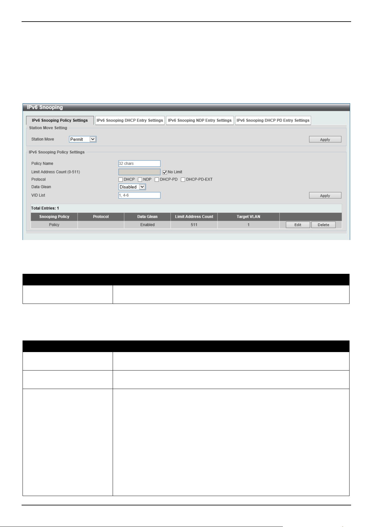
DGS-1520 Series Gigabit Ethernet Smart Managed Switch Web UI Reference Guide
446
IPv6
IPv6 Snooping
This window is used to display and configure the IPv6 snooping settings.
To view the following window, click Security > IMPB > IPv6 > IPv6 Snooping and select the IPv6 Snooping Policy
Settings tab, as shown below:
Figure 9-56 IPv6 Snooping Window
The fields that can be configured in Station Move Setting are described below:
Parameter Description
Station Move Select the station move options here. Options to choose from are Permit and
Deny.
Click the Apply button to accept the changes made.
The fields that can be configured in IPv6 Snooping Policy Settings are described below:
Parameter Description
Policy Name
Enter the IPv6 snooping policy name used here. This name can be up to 32
characters long.
Limit Address Count
Enter the address count limit value used here. This value must be between 0 and
511. Tick the No Limit option to disable this option.
Protocol
Select the protocol state here. Options to choose from are:
• DHCP - Specifies that addresses should be snooped in DHCPv6 packets.
• NDP - Specifies that addresses should be snooped in NDP packets.
• DHCP-PD - Specified that IPv6 prefix should be snooped in DHCPv6 PD
packets.
• DHCP-PD-EXT Specified that IPv6 prefix should be snooped in DHCPv6 PD
packets. PD snooping runs in the extension mode.
DHCPv6 snooping sniffs the DHCPv6 packets sent between the DHCPv6 client
and server in the address assigning procedure. When a DHCPv6 client
successfully got a valid IPv6 address, DHCPv6 snooping creates its binding
database. ND Snooping is designed for a stateless auto-configuration assigned
IPv6 address and manually configured IPv6 address. Before assigning an IPv6
address, the host must perform Duplicate Address Detection first. ND snooping
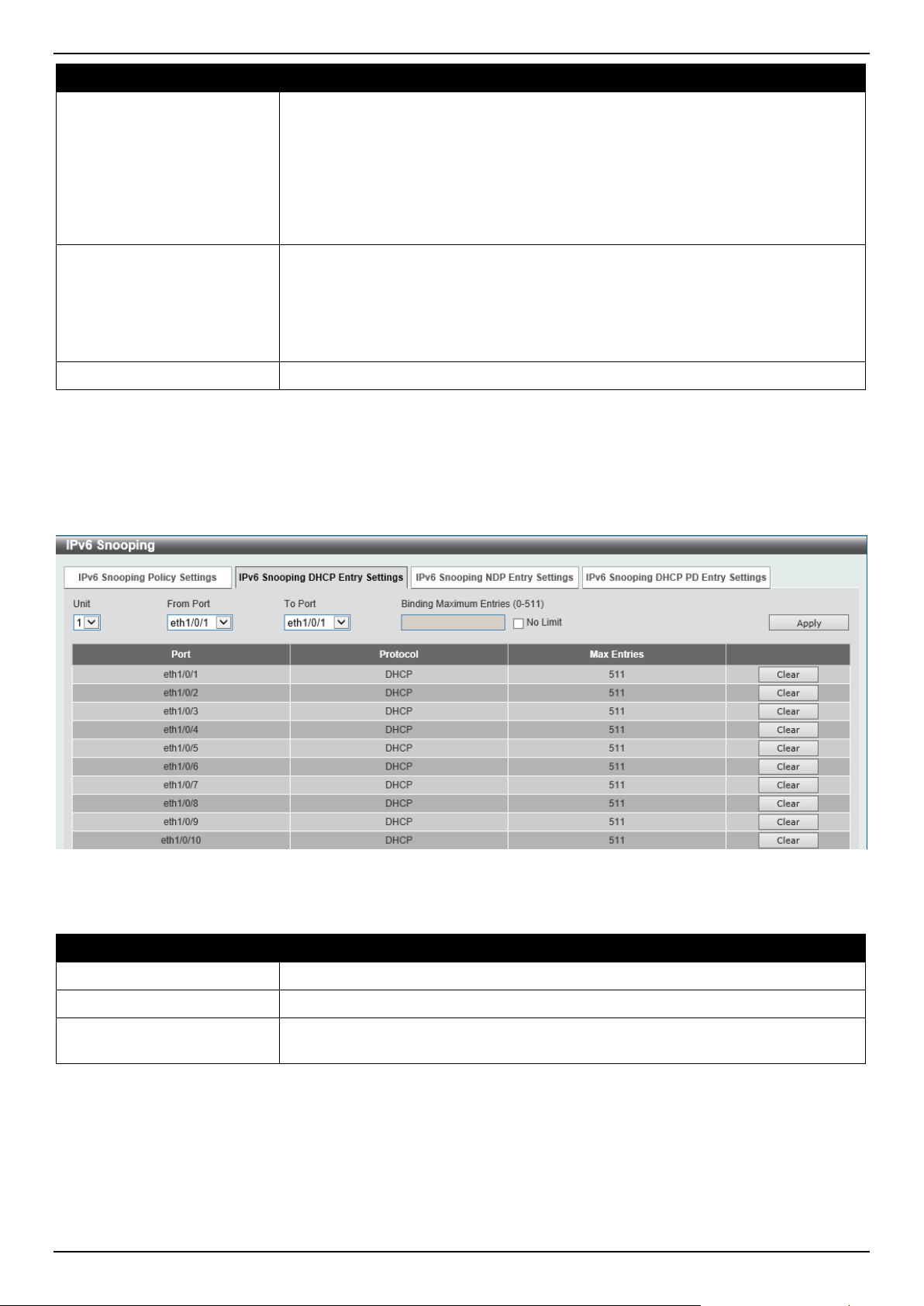
DGS-1520 Series Gigabit Ethernet Smart Managed Switch Web UI Reference Guide
447
Parameter Description
detects DAD messages (DAD Neighbor Solicitation (NS) and DAD Neighbor
Advertisement (NA)) to build its binding database. The NDP packet (NS and NA) is
also used to detect whether a host is still reachable and determine whether to
delete a binding or not.
DHCP-PD snooping performs DHCPv6 snooping of Prefix Delegation (PD) to
setup bindings between the Delegating Router (assigned with an IPv6 prefix) and
the corresponding Requesting Router. The bindings can be used to validate the
source prefix in the packets.
Data Glean
Select to enable or disable the data-glean function here. In some circumstances
(DAD-NS packet lost or Switch reboot), a valid IPv6 address cannot be found in
the binding table for some devices and as a result traffic to and from these devices
are denied by the IPv6 source guard. The data-glean function provides a method
for the Switch to recover the lost IPv6 addresses using IPv6 Duplicate Address
Detection (DAD).
VID List
Enter the VLAN ID list used here.
Click the Apply button to accept the changes made.
Click the Edit button to re-configure the specific entry.
Click the Delete button to remove the specified entry.
To view the following window, select the IPv6 Snooping DHCP Entry Settings tab, as shown below:
Figure 9-57 IPv6 Snooping (IPv6 Snooping DHCP Entry Settings) Window
The fields that can be configured are described below:
Parameter Description
Unit
Select the Switch stacking unit ID here.
From Port - To Port
Select the range of ports that will be used here.
Binding Max Entries
Enter the maximum number of IPv6 snooping binding entries that is allowed here.
The range is from 0 to 511.
Click the Apply button to accept the changes made.
Click the Clear button to clear DHCPv6 snooping entries from the specified port.
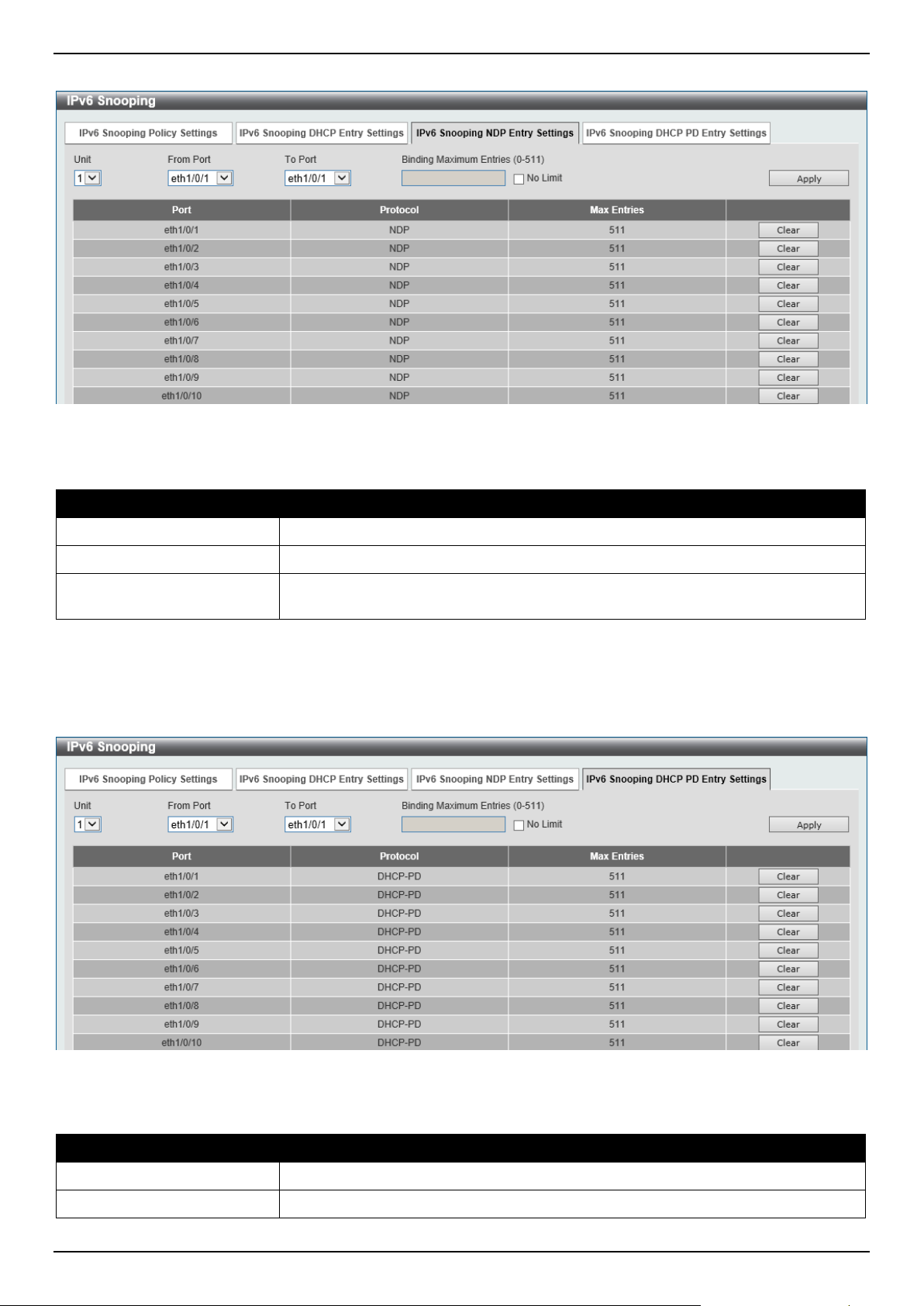
DGS-1520 Series Gigabit Ethernet Smart Managed Switch Web UI Reference Guide
448
To view the following window, select the IPv6 Snooping NDP Entry Settings tab, as shown below:
Figure 9-58 IPv6 Snooping (IPv6 Snooping NDP Entry Settings) Window
The fields that can be configured are described below:
Parameter Description
Unit
Select the Switch stacking unit ID here.
From Port - To Port
Select the range of ports that will be used here.
Binding Max Entries
Enter the maximum number of IPv6 snooping binding entries that is allowed here.
The range is from 0 to 511.
Click the Apply button to accept the changes made.
Click the Clear button to clear ND snooping entries from the specified port.
To view the following window, select the IPv6 Snooping DHCP-PD Entry Settings tab, as shown below:
Figure 9-59 IPv6 Snooping (IPv6 Snooping DHCP-PD Entry Settings) Window
The fields that can be configured are described below:
Parameter Description
Unit
Select the Switch stacking unit ID here.
From Port - To Port
Select the range of ports that will be used here.

DGS-1520 Series Gigabit Ethernet Smart Managed Switch Web UI Reference Guide
449
Parameter Description
Binding Max Entries
Enter the maximum number of IPv6 snooping binding entries that is allowed here.
The range is from 0 to 511.
Click the Apply button to accept the changes made.
Click the Clear button to clear DHCPv6 PD snooping entries from the specified port.
IPv6 ND Inspection
This window is used to display and configure the IPv6 ND inspection settings.
To view the following window, click Security > IMPB > IPv6 > IPv6 ND Inspection, as shown below:
Figure 9-60 IPv6 ND Inspection Window
The fields that can be configured are described below:
Parameter Description
Policy Name
Enter the policy name used here. This name can be up to 32 characters long.
Device Role Select the device role here. Options to choose from are Host and Router. By
default, the device's role is set as host and inspection for NS and NA messages
are performed. If the device role is set as router, the NS and NA inspection is not
performed. When performing NS/NA inspection, the message will be verified
against the dynamic binding table learned from the ND protocol or from the DHCP.
Mode
Select the mode of ND inspection here. Options to choose from are:
• Precise - Specifies to use the precise mode. ND inspection checks if the
target address is the same as the source address in DANA/NA packets.
• Fuzzy - Specifies to use the fuzzy mode. ND inspection checks if both the
target and the source addresses exist in the binding table.
Validate Source-MAC
Select to enable or disable the validation of the source MAC address option here.
When the Switch receives an ND message that contains a link-layer address, the
source MAC address is checked against the link-layer address. The packet will be
dropped if the link-layer address and the MAC addresses are different from each
other.
Target Port
Tick this option to specify the target port.
Unit
Select the Switch unit that will be used for this configuration here.
From Port - To Port
Select the appropriate port range used for the configuration here.
Click the Apply button to accept the changes made.
Click the Edit button to re-configure the specific entry.
Click the Delete button to remove the specified entry.
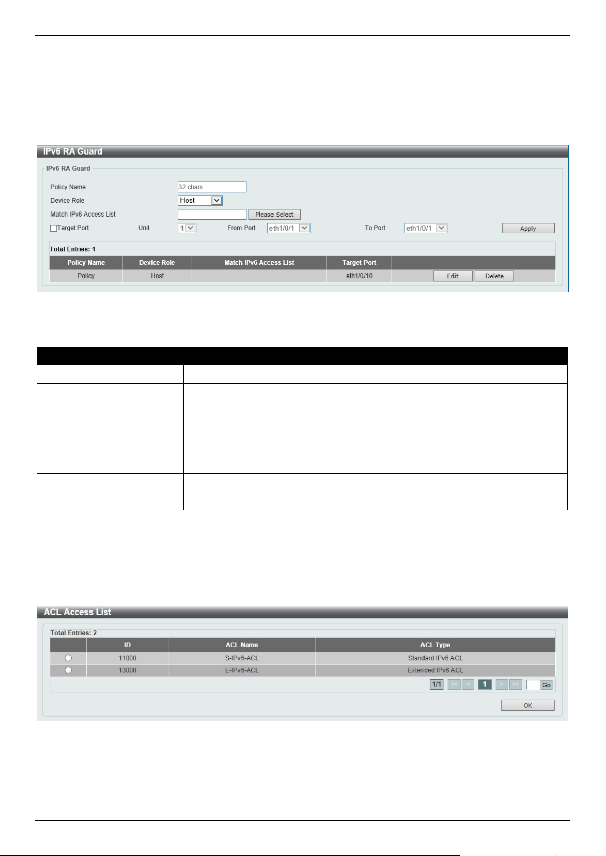
DGS-1520 Series Gigabit Ethernet Smart Managed Switch Web UI Reference Guide
450
IPv6 RA Guard
This window is used to display and configure the IPv6 Router Advertisement (RA) guard settings.
To view the following window, click Security > IMPB > IPv6 > IPv6 RA Guard, as shown below:
Figure 9-61 IPv6 RA Guard Window
The fields that can be configured are described below:
Parameter Description
Policy Name
Enter the policy name here. This name can be up to 32 characters long.
Device Role Select the device role here. Options to choose from are Host and Router. By
default, the device's role is Host, which will block all the RA packets. If the device's
role is Router, RA packets will be forwarded according to the port's bound ACL.
Match IPv6 Access List Enter or select the IPv6 access list to match here. Click the Please Select button
to select an existing ACL from the list.
Target Port
Tick this option to specify the target port.
Unit
Select the Switch unit that will be used for this configuration here.
From Port - To Port
Select the appropriate port range used for the configuration here.
Click the Apply button to accept the changes made.
Click the Edit button to re-configure the specific entry.
Click the Delete button to remove the specified entry.
After clicking the Please Select button, the following window will appear:
Figure 9-62 ACL Access List Window
Select the radio button next to the entry to use that ACL in the configuration.
Enter a page number and click the Go button to navigate to a specific page when multiple pages exist.
Click the OK button to accept the selection made.
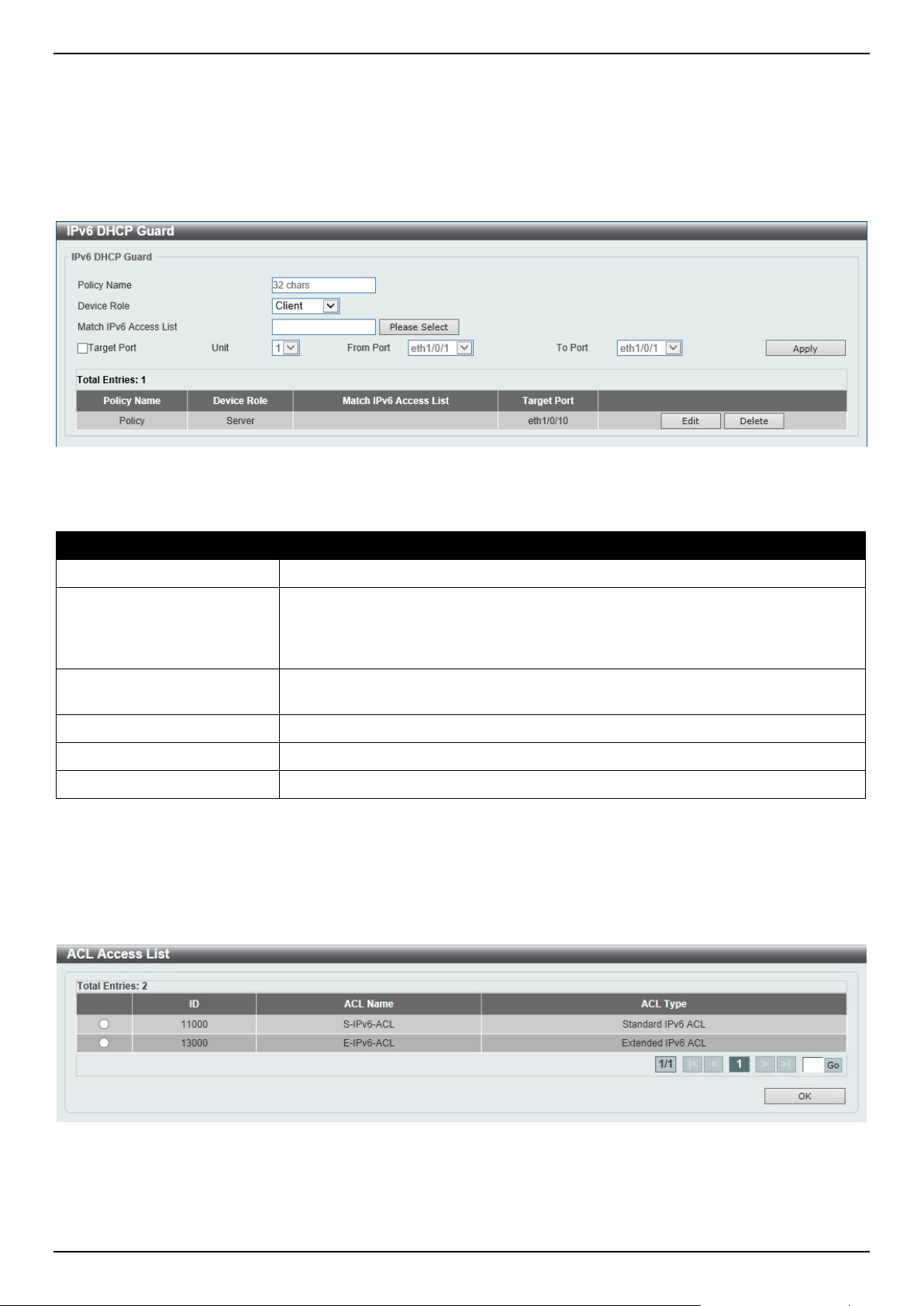
DGS-1520 Series Gigabit Ethernet Smart Managed Switch Web UI Reference Guide
451
IPv6 DHCP Guard
This window is used to display and configure the IPv6 DHCP guard settings.
To view the following window, click Security > IMPB > IPv6 > IPv6 DHCP Guard, as shown below:
Figure 9-63 IPv6 DHCP Guard Window
The fields that can be configured are described below:
Parameter Description
Policy Name
Enter the policy name here. This name can be up to 32 characters long.
Device Role Select the device role here. Options to choose from are Client and Server. By
default, the device's role is set as Client, which will block all the DHCPv6 packets
from the DHCPv6 Server. If the device's role is set as Server, DHCPv6 Server
packets will be forwarded according to the port's bound ACL.
Match IPv6 Access List Enter or select the IPv6 access list to match here. Click the Please Select button
to select an existing ACL from the list.
Target Port
Tick this option to specify the target port.
Unit
Select the Switch unit that will be used for this configuration here.
From Port - To Port
Select the appropriate port range used for the configuration here.
Click the Apply button to accept the changes made.
Click the Edit button to re-configure the specific entry.
Click the Delete button to remove the specified entry.
After clicking the Please Select button, the following window will appear:
Figure 9-64 ACL Access List Window
Select the radio button next to the entry to use that ACL in the configuration.
Enter a page number and click the Go button to navigate to a specific page when multiple pages exist.
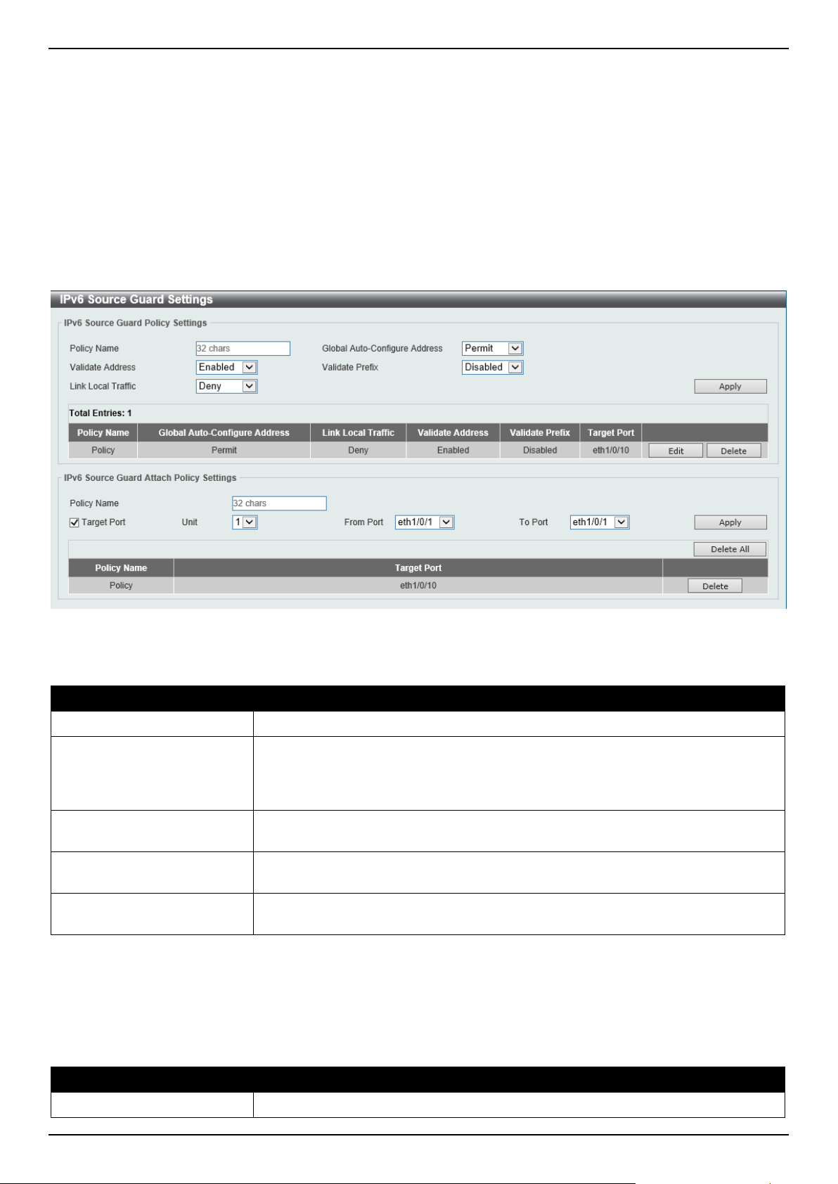
DGS-1520 Series Gigabit Ethernet Smart Managed Switch Web UI Reference Guide
452
Click the OK button to accept the selection made.
IPv6 Source Guard
IPv6 Source Guard Settings
This window is used to display and configure the IPv6 source guard settings.
To view the following window, click Security > IMPB > IPv6 > IPv6 Source Guard > IPv6 Source Guard Settings,
as shown below:
Figure 9-65 IPv6 Source Guard Settings Window
The fields that can be configured in IPv6 Source Guard Policy Settings are described below:
Parameter Description
Policy Name
Enter the policy name here. This name can be up to 32 characters long.
Global Auto-Configure
Address
Select to permit of deny data traffic from the auto-configured global address. It is
useful when all global addresses on a link are assigned by DHCP and the
administrator that wants to block hosts with self-configured addresses from
sending traffic.
Validate Address
Select to enable or disable the validate address feature here. This is used to
enable the IPv6 source guard to perform the validate address feature.
Validate Prefix
Select to enable or disable the validate prefix feature here. This is used to enable
the IPv6 source guard to perform the IPv6 prefix-guard operation.
Link Local Traffic
Select to permit of deny hardware permitted data traffic send by the link-local
address.
Click the Apply button to accept the changes made.
Click the Edit button to re-configure the specific entry.
Click the Delete button to remove the specified entry.
The fields that can be configured in IPv6 Source Guard Attach Policy Settings are described below:
Parameter Description
Policy Name
Enter the policy name here. This name can be up to 32 characters long.
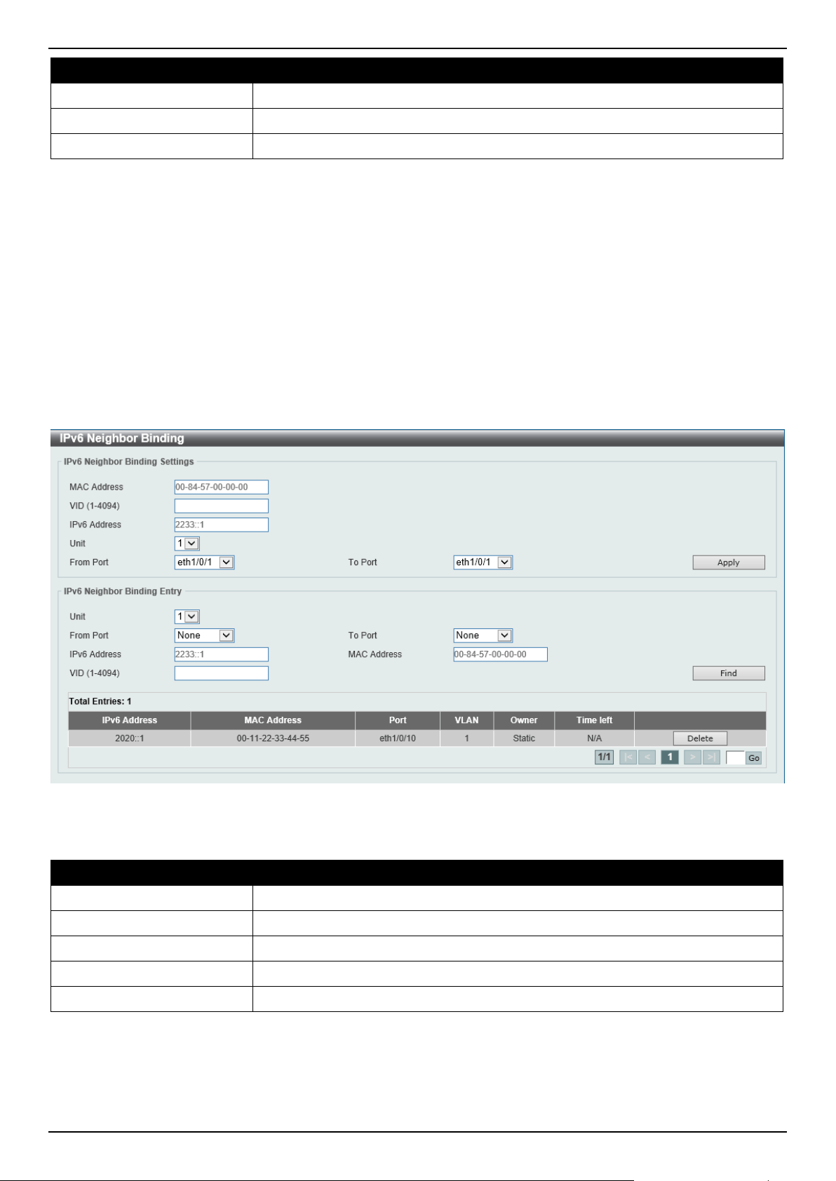
DGS-1520 Series Gigabit Ethernet Smart Managed Switch Web UI Reference Guide
453
Parameter Description
Target Port
Select this option to specify the target port.
Unit
Select the Switch unit that will be used for this configuration here.
From Port - To Port
Select the appropriate port range used for the configuration here.
Click the Apply button to accept the changes made.
Click the Delete All button to remove all the entries.
Click the Delete button to remove the specified entry.
Enter a page number and click the Go button to navigate to a specific page when multiple pages exist.
IPv6 Neighbor Binding
This window is used to display and configure the IPv6 neighbor binding settings.
To view the following window, click Security > IMPB > IPv6 > IPv6 Source Guard > IPv6 Neighbor Binding, as
shown below:
Figure 9-66 IPv6 Neighbor Binding Window
The fields that can be configured in IPv6 Neighbor Binding Settings are described below:
Parameter Description
MAC Address
Enter the MAC address used here.
VID
Enter the VLAN ID used here. This value must be between 1 and 4094.
IPv6 Address
Enter the IPv6 address used here.
Unit
Select the Switch unit that will be used for this configuration here.
From Port - To Port
Select the appropriate port range used for the configuration here.
Click the Apply button to accept the changes made.
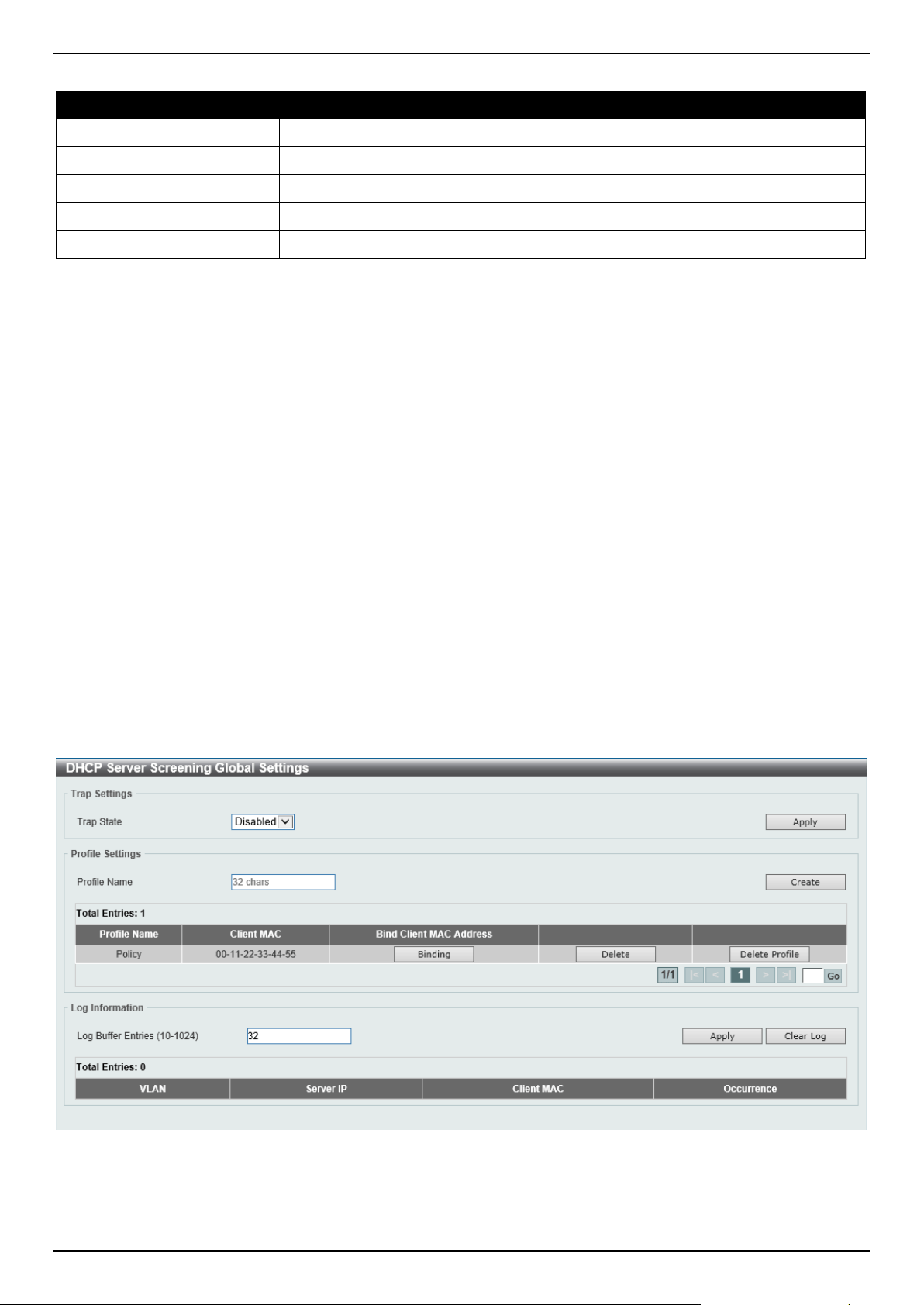
DGS-1520 Series Gigabit Ethernet Smart Managed Switch Web UI Reference Guide
454
The fields that can be configured in IPv6 Neighbor Binding Entry are described below:
Parameter Description
Unit
Select the Switch unit that will be used for this search here.
From Port - To Port
Select the appropriate port range used for the search here.
IPv6 Address
Enter the IPv6 address to find here.
MAC Address
Enter the MAC address to find here.
VID
Enter the VLAN ID to find here.
Click the Find button to locate a specific entry based on the information entered.
Click the Delete button to remove the specified entry.
Enter a page number and click the Go button to navigate to a specific page when multiple pages exist.
DHCP Server Screening
This function allows users to not only to restrict all DHCP server packets but also to receive any specified DHCP
server packet by any specified DHCP client. It is useful when one or more DHCP servers are present on the network
and both provide DHCP services to different distinct groups of clients.
When the DHCP Server Screening function is enabled on a port, all DHCP server packets received on this ports will
be redirected to the CPU for a software-based check. Legal DHCP server packets will be forwarded out and illegal
DHCP server packets will be dropped. When DHCP Server Screening function is enabled, all DHCP server packets
will be filtered from a specific port.
DHCP Server Screening Global Settings
This window is used to display and configure the global DHCP server screening settings.
To view the following window, click Security > DHCP Server Screening > DHCP Server Screening Global
Settings, as shown below:
Figure 9-67 DHCP Server Screening Global Settings Window
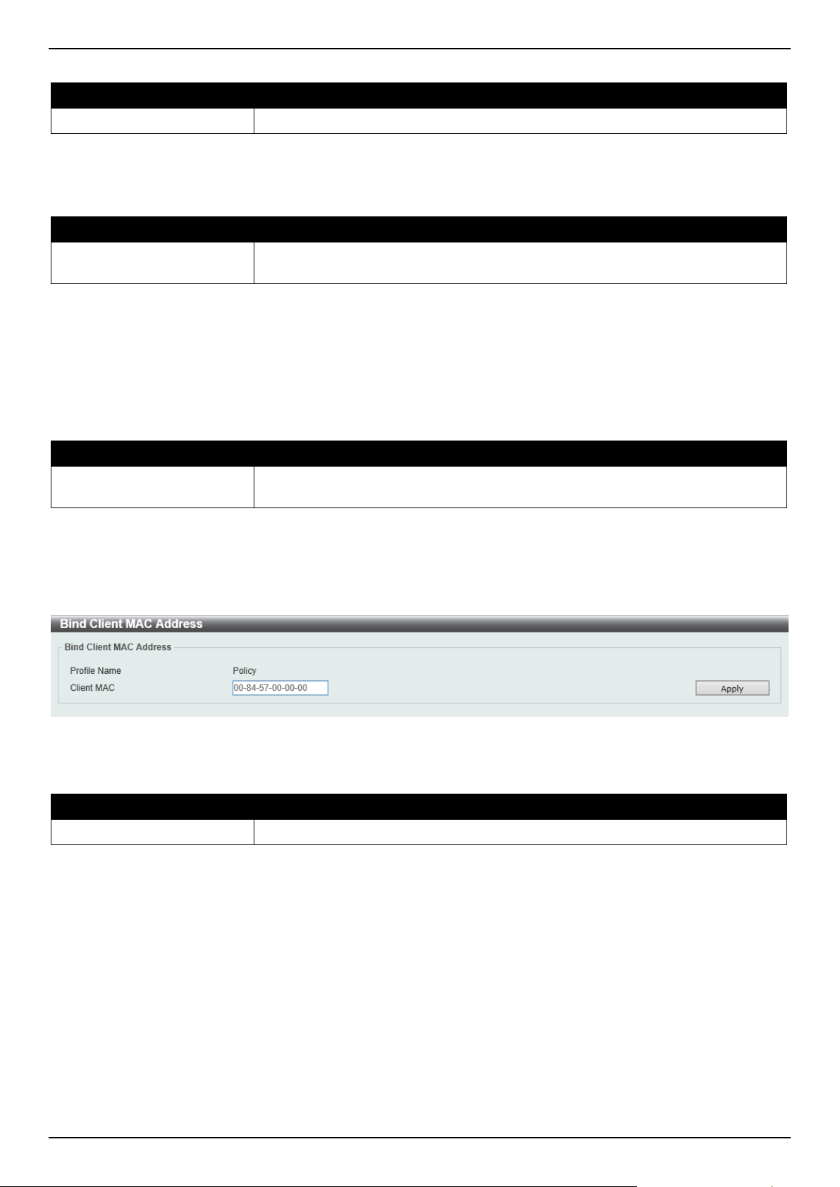
DGS-1520 Series Gigabit Ethernet Smart Managed Switch Web UI Reference Guide
455
The fields that can be configured in Trap Settings are described below:
Parameter Description
Trap State
Select to enable or disable the DHCP server-screening trap here.
Click the Apply button to accept the changes made.
The fields that can be configured in Profile Settings are described below:
Parameter Description
Profile Name
Enter the DHCP server screening profile name here. This name can be up to 32
characters long.
Click the Create button to create a new profile.
Click the Binding button to configure the client MAC address in the profile.
Click the Delete button to remove the specified entry.
Click the Delete Profile button to remove the specified profile.
The fields that can be configured in Log Information are described below:
Parameter Description
Log Buffer Entries
Enter the logged buffer entries value here. This value must be between 10 and
1024. By default, this value is 32.
Click the Apply button to accept the changes made.
Click the Clear Log button to clear the log.
After clicking the Binding button, the following window will appear:
Figure 9-68 Bind Client MAC Address Window
The fields that can be configured are described below:
Parameter Description
Client MAC
Enter the MAC address used here.
Click the Apply button to accept the changes made.
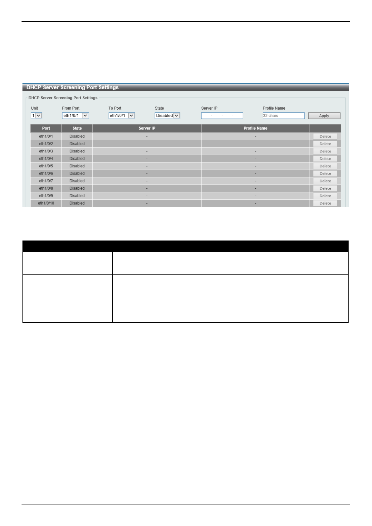
DGS-1520 Series Gigabit Ethernet Smart Managed Switch Web UI Reference Guide
456
DHCP Server Screening Port Settings
This window is used to display and configure the DHCP server screening port settings.
To view the following window, click Security > DHCP Server Screening > DHCP Server Screening Port Settings,
as shown below:
Figure 9-69 DHCP Server Screening Port Settings Window
The fields that can be configured are described below:
Parameter Description
Unit
Select the Switch unit that will be used for this configuration here.
From Port - To Port
Select the appropriate port range used for the configuration here.
State
Select to enable or disable the DHCP server screening function on the port(s)
specified.
Server IP
Enter the DHCP server IP address here.
Profile Name
Enter the DHCP server screening profile that will be used for the port(s) specified
here.
Click the Apply button to accept the changes made.
Click the Delete button to remove the specified entry.
ARP Spoofing Prevention
This window is used to display and configure the ARP spoofing prevention settings. When an entry is created, ARP
packets whose sender IP address matches the gateway IP address, of an entry, but its sender MAC address field
does not match the gateway MAC address, of the entry, will be dropped by the system. The ASP will bypass the ARP
packets whose sender IP address doesn't match the configured gateway IP address.
If an ARP address matches a configured gateway's IP address, MAC address, and port list, then bypass the Dynamic
ARP Inspection (DAI) check no matter if the receiving port is ARP trusted or untrusted.
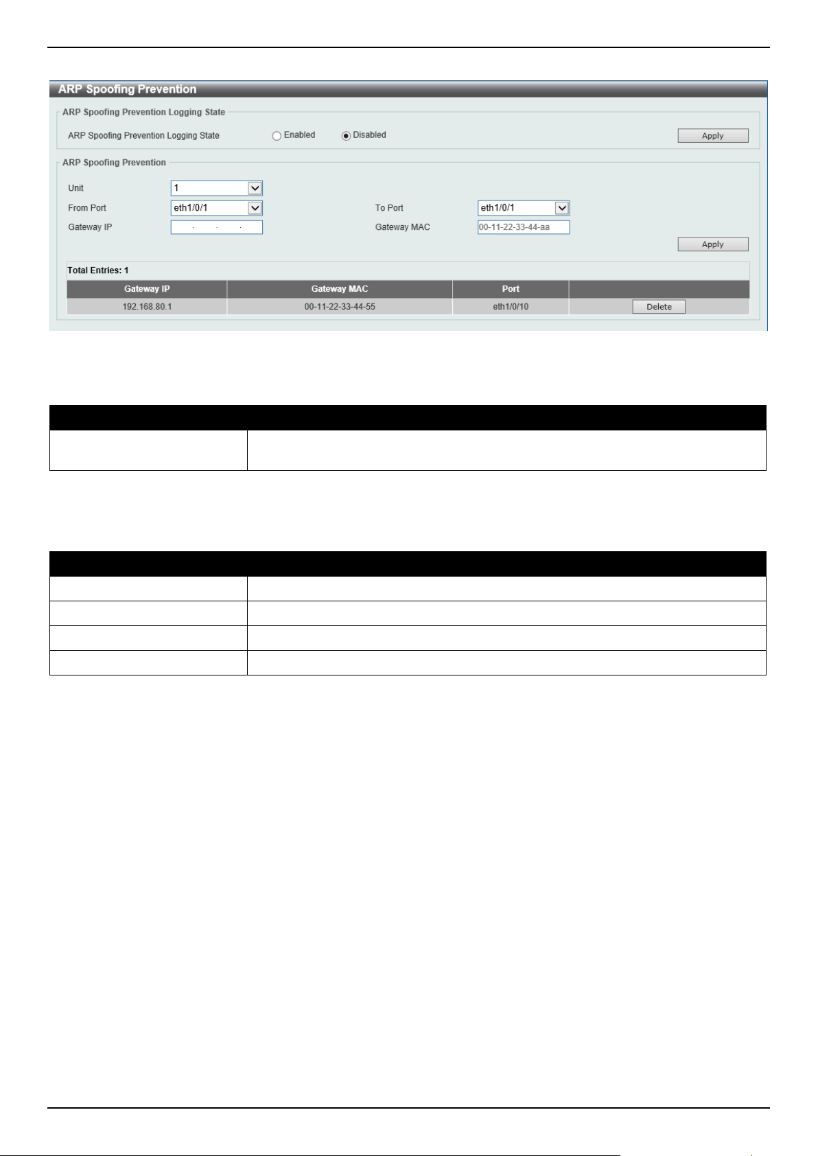
DGS-1520 Series Gigabit Ethernet Smart Managed Switch Web UI Reference Guide
457
To view the following window, click Security > ARP Spoofing Prevention, as shown below:
Figure 9-70 ARP Spoofing Prevention Window
The fields that can be configured in ARP Spoofing Prevention Logging State are described below:
Parameter Description
ARP Spoofing Prevention
Logging State
Select to enable or disable the ARP spoofing prevention logging state here.
Click the Apply button to accept the changes made.
The fields that can be configured in ARP Spoofing Prevention are described below:
Parameter Description
Unit
Select the Switch unit that will be used for this configuration here.
From Port - To Port
Select the appropriate port range used for the configuration here.
Gateway IP
Enter the gateway IP address used here.
Gateway MAC
Enter the gateway MAC address used here.
Click the Apply button to accept the changes made.
Click the Delete button to remove the specified entry.
BPDU Attack Protection
This window is used to display and configure the BPDU attack protection settings. In generally, there are two states in
the BPDU attack protection function. One is normal state, and another is under attack state. The under attack state
has three modes: drop, block, and shutdown. A BPDU protection enabled port will enter an under attack state when it
receives one STP BPDU packet and it will take action based on the configuration.
BPDU protection has a higher priority than the (Forward BPDU) FBPDU setting configured by configure STP
command in the determination of BPDU handling. That is, when FBPDU is configured to forward STP BPDU but
BPDU protection is enabled, then the port will not forward STP BPDU.
BPDU protection also has a higher priority than the BPDU tunnel port setting in determination of BPDU handling. That
is, when a port is configured as BPDU tunnel port for STP, it will forward STP BPDU. However, if the port is BPDU
protection enabled. Then the port will not forward STP BPDU.
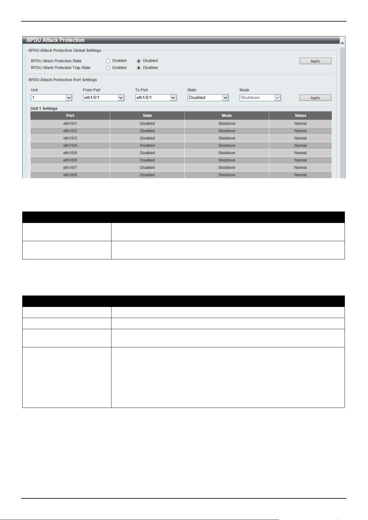
DGS-1520 Series Gigabit Ethernet Smart Managed Switch Web UI Reference Guide
458
To view the following window, click Security > BPDU Attack Protection, as shown below:
Figure 9-71 BPDU Attack Protection Window
The fields that can be configured in BPDU Attack Protection Global Settings are described below:
Parameter Description
BPDU Attack Protection
State
Select to enable or disable the global BPDU attack protection state here.
BPDU Attack Protection
Trap State
Select to enable or disable the BPDU attack protection trap state here.
Click the Apply button to accept the changes made.
The fields that can be configured in BPDU Attack Protection Port Settings are described below:
Parameter Description
Unit
Select the Switch unit that will be used for this configuration here.
From Port - To Port
Select the appropriate port range used for the configuration here.
State
Select to enable or disable the BPDU attack protection state on the port(s)
specified.
Mode
Select the BPDU attack protection mode that will be applied to the port(s)
specified. Options to choose from are:
• Drop - Drop all received BPDU packets when the port enters under attack
state.
• Block - Drop all packets (include BPDU and normal packets) when the port
enters under attack state.
• Shutdown - Shut down the port when the port enters under attack state.
Click the Apply button to accept the changes made.
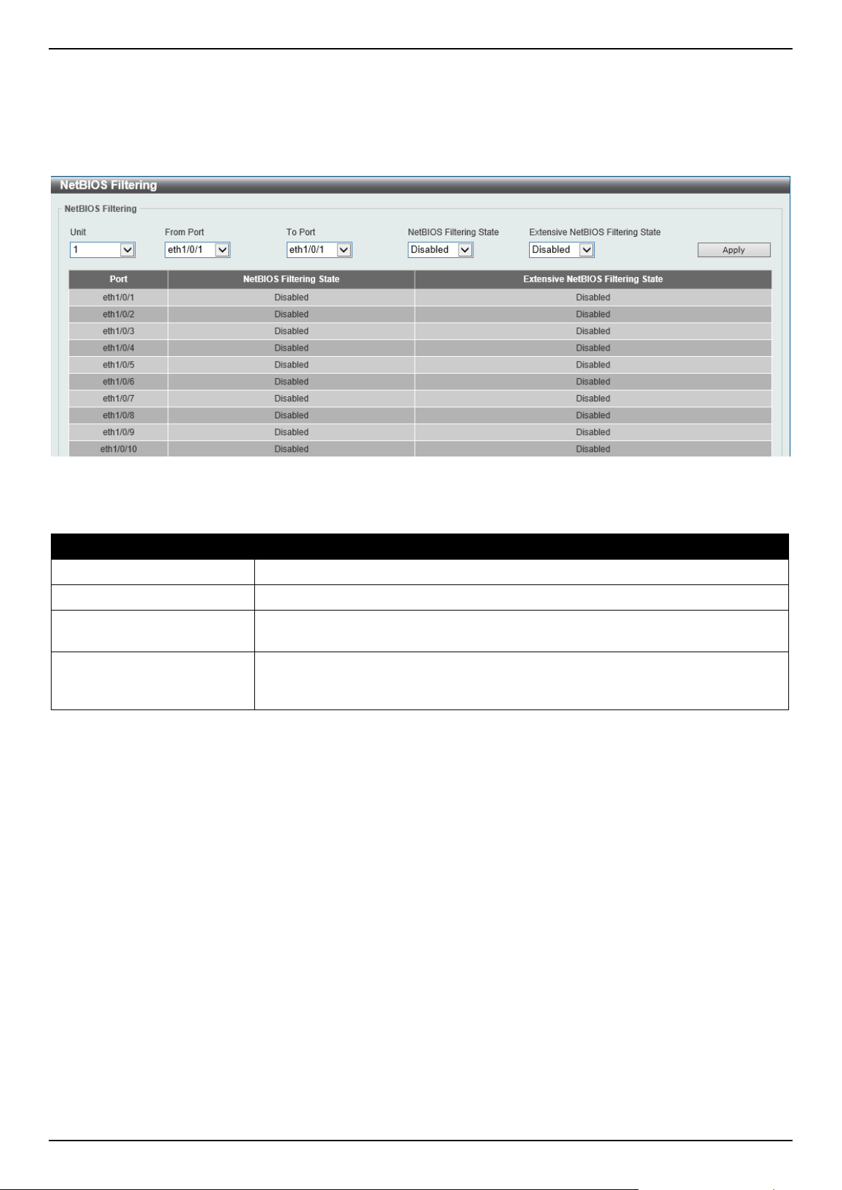
DGS-1520 Series Gigabit Ethernet Smart Managed Switch Web UI Reference Guide
459
NetBIOS Filtering
This window is used to display and configure the NetBIOS filtering settings.
To view the following window, click Security > NetBIOS Filtering, as shown below:
Figure 9-72 NetBIOS Filtering Window
The fields that can be configured are described below:
Parameter Description
Unit
Select the Switch unit that will be used for this configuration here.
From Port - To Port
Select the range of ports that will be used for this configuration here.
NetBIOS Filtering State
Select to enable or disable the NetBIOS filtering state on the specified port(s). This
is used to permit or deny NetBIOS packets on physical ports.
Extensive NetBIOS Filtering
State
Select to enable or disable the extensive NetBIOS filtering state on the specified
port(s). This is used to permit or deny NetBIOS packets over 802.3 frames on
physical ports.
Click the Apply button to accept the changes made.
MAC Authentication
This window is used to display and configure the MAC authentication settings. MAC authentication is a feature
designed to authenticate a user by MAC address when the user is trying to access the network via the Switch. The
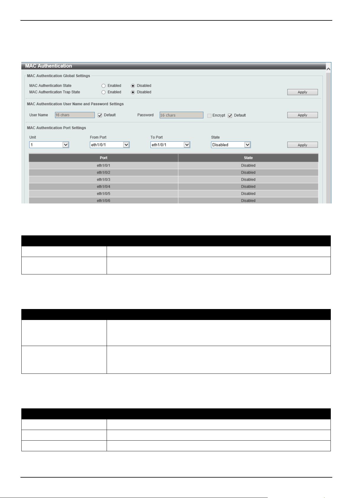
DGS-1520 Series Gigabit Ethernet Smart Managed Switch Web UI Reference Guide
460
Switch itself can perform the authentication based on a local database or be a RADIUS client and perform the
authentication process via the RADIUS protocol with a remote RADIUS server.
To view the following window, click Security > MAC Authentication, as shown below:
Figure 9-73 MAC Authentication Window
The fields that can be configured in MAC Authentication Global Settings are described below:
Parameter Description
MAC Authentication State
Select to enable or disable the global MAC authentication state.
MAC Authentication Trap
State
Select to enable or disable the MAC authentication trap state.
Click the Apply button to accept the changes made.
The fields that can be configured in MAC Authentication User Name and Password Settings are described below:
Parameter Description
User Name
Enter the username used for MAC authentication here. This name can be up to 16
characters long.
Tick the Default option to restore the username to the client MAC address here.
Password
Enter the password used for MAC authentication here.
Tick the Encrypt option save this password in the encrypted form.
Tick the Default option to restore the password to the client MAC address here.
Click the Apply button to accept the changes made.
The fields that can be configured in MAC Authentication Port Settings are described below:
Parameter Description
Unit
Select the Switch unit that will be used for this configuration here.
From Port - To Port
Select the appropriate port range used for the configuration here.
State
Select to enable or disable MAC authentication for the port(s) specified here.
Click the Apply button to accept the changes made.

DGS-1520 Series Gigabit Ethernet Smart Managed Switch Web UI Reference Guide
461
Web-based Access Control
Web-based Access Control (WAC) is a feature designed to authenticate a user when the user is trying to access the
Internet via the Switch. The authentication process uses the HTTP or HTTPS protocol. The Switch enters the
authenticating stage when users attempt to browse Web pages (e.g., http://www.dlink.com) through a Web browser.
When the Switch detects HTTP or HTTPS packets and this port is unauthenticated, the Switch will launch a pop-up
user name and password window to query users. Users are not able to access the Internet until the authentication
process is passed.
The Switch can be the authentication server itself and do the authentication based on a local database, or be a
RADIUS client and perform the authentication process via the RADIUS protocol with a remote RADIUS server. The
client user initiates the authentication process of WAC by attempting to gain Web access.
D-Link's implementation of WAC uses a virtual IP that is exclusively used by the WAC function and is not known by
any other modules of the Switch. In fact, to avoid affecting a Switch's other features, WAC will only use a virtual IP
address to communicate with hosts. Thus, all authentication requests must be sent to a virtual IP address but not to
the IP address of the Switch's physical interface.
Virtual IP works like this, when a host PC communicates with the WAC Switch through a virtual IP, the virtual IP is
transformed into the physical IPIF (IP interface) address of the Switch to make the communication possible. The host
PC and other servers' IP configurations do not depend on the virtual IP of WAC. The virtual IP does not respond to
any ICMP packets or ARP requests, which means it is not allowed to configure a virtual IP on the same subnet as the
Switch's IPIF (IP interface) or the same subnet as the host PCs' subnet.
As all packets to a virtual IP from authenticated and authenticating hosts will be trapped to the Switch's CPU, if the
virtual IP is the same as other servers or PCs, the hosts on the WAC-enabled ports cannot communicate with the
server or PC, which really own the IP address. If the hosts need to access the server or PC, the virtual IP cannot be
the same as the one of the server or PC. If a host PC uses a proxy to access the Web, to make the authentication
work properly the user of the PC should add the virtual IP to the exception of the proxy configuration. If the virtual IP is
not configured, then access cannot start Web authentication.
The Switch's implementation of WAC features a user-defined port number that allows the configuration of the TCP
port for either the HTTP or HTTPS protocols. This TCP port for HTTP or HTTPs is used to identify the HTTP or HTTPs
packets that will be trapped to the CPU for authentication processing, or to access the login page. By default, HTTP is
used. By default, the HTTP port number is 80, and HTTPS port number is 443.
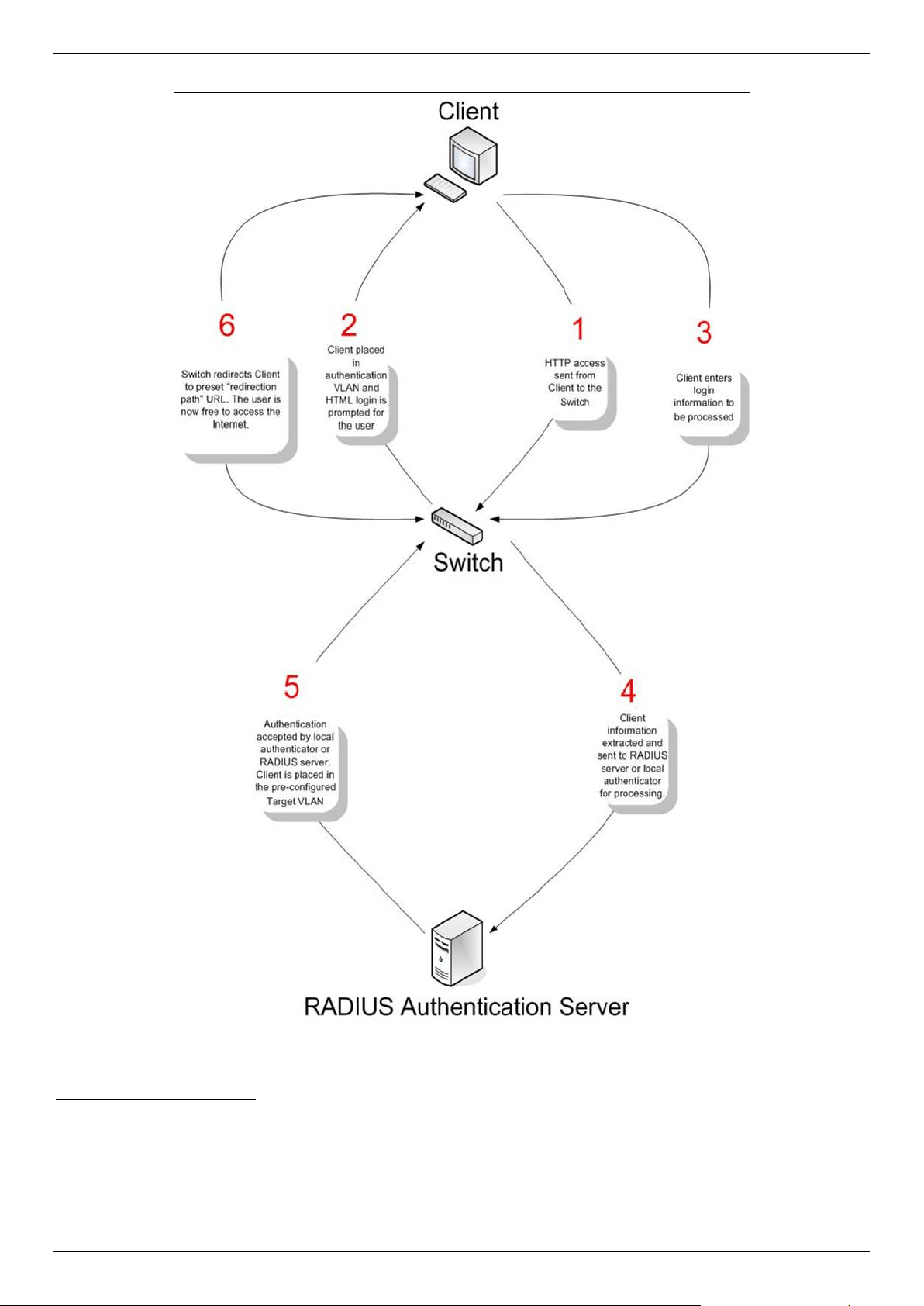
DGS-1520 Series Gigabit Ethernet Smart Managed Switch Web UI Reference Guide
462
The following diagram illustrates the basic six steps all parties go through in a successful Web Authentication process:
Figure 9-74 RADIUS Authentication Server
Conditions and Limitations
• If the client is utilizing DHCP to attain an IP address, the authenticating VLAN must provide a DHCP server or a
DHCP relay function so that client may obtain an IP address.
• Certain functions exist on the Switch that will filter HTTP packets, such as the ACL function. The user needs to
be very careful when setting filter functions for the target VLAN, so that these HTTP packets are not denied by
the Switch.
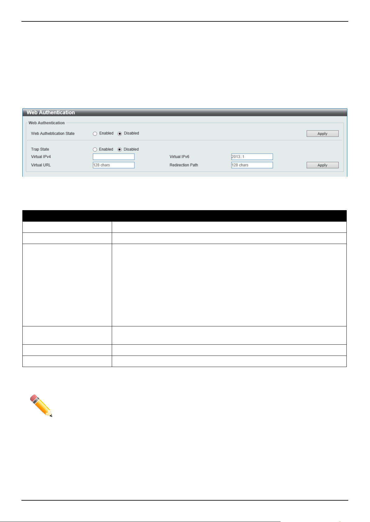
DGS-1520 Series Gigabit Ethernet Smart Managed Switch Web UI Reference Guide
463
• If a RADIUS server is to be used for authentication, the user must first establish a RADIUS Server with the
appropriate parameters, including the target VLAN, before enabling Web Authentication on the Switch.
Web Authentication
This window is used to display and configure the Web authentication settings.
To view the following window, click Security > Web-based Access Control > Web Authentication, as shown below:
Figure 9-75 Web Authentication Window
The fields that can be configured are described below:
Parameter Description
Web Authentication State
Select to enable or disable the global Web authentication state.
Trap State
Select to enable or disable the Web authentication trap state.
Virtual IPv4
Enter the virtual IPv4 address used here. The virtual IP of Web authentication is
just the characterization of the Web authentication function on the Switch. All Web
authentication processes communicate with this IP address, however, the virtual IP
does not respond to any ICMP packet or ARP request. Therefore, it's not allowed
to configure virtual IP in the same subnet as the Switch's IP interface or the same
subnet as the host PCs' subnet, otherwise the Web authentication cannot operate
correctly. The defined URL only takes effect when the virtual IP address is
configured. The users get the FQDN URL stored on the DNS server to get the
virtual IP address. The obtained IP address must match the virtual IP address
configured by the command. If the IPv4 virtual IP is not configured, the IPv4
access cannot start a Web authentication.
Virtual IPv6
Enter the virtual IPv6 address used here. If the IPv6 virtual IP is not configured, the
IPv6 access cannot start a Web authentication.
Virtual URL
Enter the virtual URL used here. This URL can be up to 128 characters long.
Redirection Path
Enter the redirection path here. This path can be up to 128 characters long.
Click the Apply button to accept the changes made.
NOTE: The WAC virtual IP address should be configured before enabling WAC because WAC will
not function correctly if the virtual IP is not configured.
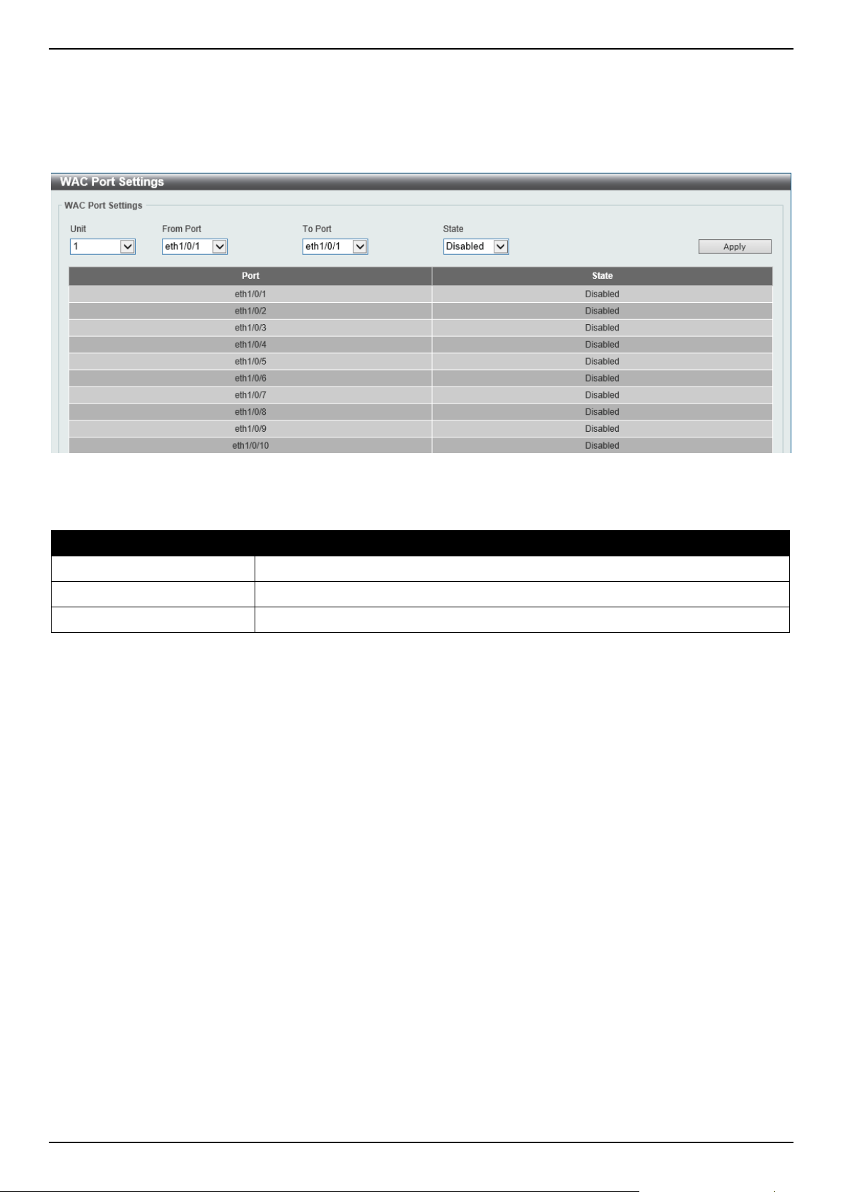
DGS-1520 Series Gigabit Ethernet Smart Managed Switch Web UI Reference Guide
464
WAC Port Settings
This window is used to display and configure the WAC port settings.
To view the following window, click Security > Web-based Access Control > WAC Port Settings, as shown below:
Figure 9-76 WAC Port Settings Window
The fields that can be configured are described below:
Parameter Description
Unit
Select the Switch unit that will be used for this configuration here.
From Port - To Port
Select the appropriate port range used for the configuration here.
State
Select to enable or disable the WAC feature on the port(s) specified.
Click the Apply button to accept the changes made.
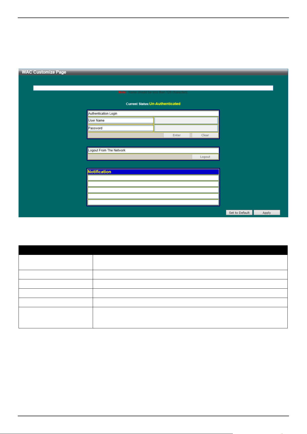
DGS-1520 Series Gigabit Ethernet Smart Managed Switch Web UI Reference Guide
465
WAC Customize Page
This window is used to display and configure the WAC customized login page.
To view the following window, click Security > Web-based Access Control > WAC Customize Page, as shown
below:
Figure 9-77 WAC Customize Page Window
The fields that can be configured are described below:
Parameter Description
Page Title
Enter a custom page title message here. This message can be up to 128
characters long.
Login Window Title
Enter a custom login window title here. This title can be up to 64 characters long.
User Name Title
Enter a custom username title here. This title can be up to 32 characters long.
Password Title
Enter a custom password title here. This title can be up to 32 characters long.
Logout Window Title
Enter a custom logout window title here. This title can be up to 64 characters long.
Notification
Enter additional information to display in the notification area here. This information
can be up to 128 characters long for each line. There a 5 lines available for
additional information.
Click the Set to Default button to replace the information with the default information.
Click the Apply button to accept the changes made.
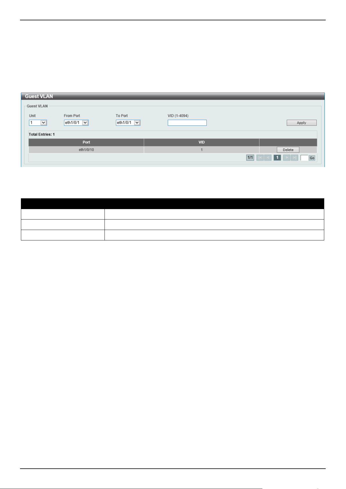
DGS-1520 Series Gigabit Ethernet Smart Managed Switch Web UI Reference Guide
466
Network Access Authentication
Guest VLAN
This window is used to display and configure the network access authentication guest VLAN settings.
To view the following window, click Security > Network Access Authentication > Guest VLAN, as shown below:
Figure 9-78 Guest VLAN Window
The fields that can be configured are described below:
Parameter Description
Unit
Select the Switch unit that will be used for this configuration here.
From Port - To Port
Select the appropriate port range used for the configuration here.
VID
Enter the VLAN ID used here. This value must be between 1 and 4094.
Click the Apply button to accept the changes made.
Click the Delete button to remove the specified entry.
Enter a page number and click the Go button to navigate to a specific page when multiple pages exist.
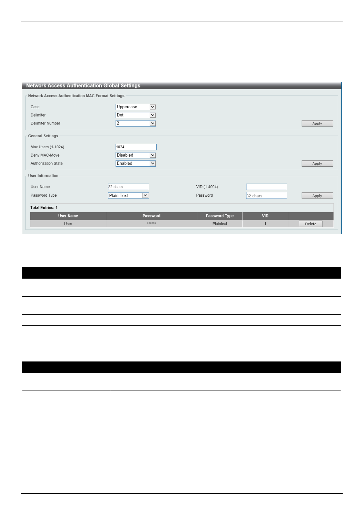
DGS-1520 Series Gigabit Ethernet Smart Managed Switch Web UI Reference Guide
467
Network Access Authentication Global Settings
This window is used to display and configure the global Network Access Authentication settings.
To view the following window, click Security > Network Access Authentication > Network Access Authentication
Global Settings, as shown below:
Figure 9-79 Network Access Authentication Global Settings Window
The fields that can be configured in Network Access Authentication MAC Format Settings are described below:
Parameter Description
Case
Select the case format that will be used for the network access authentication MAC
address here. Options to choose from are Lowercase and Uppercase.
Delimiter
Select the delimiter that will be used for the network access authentication MAC
address here. Options to choose from are Hyphen, Colon, Dot, and None.
Delimiter Number Select the delimiter number option here. Options to choose from are 1, 2, and 5.
Click the Apply button to accept the changes made.
The fields that can be configured in General Settings are described below:
Parameter Description
Max Users
Enter the maximum amount of users allowed here. This value must be between 1
and 1024. By default, this value is 1024.
Deny MAC-Move
Select to enable or disable the deny MAC-move feature here. This option controls
whether to allow authenticated hosts to do roaming across different Switch ports
and only controls whether a host, which is authenticated at a port set to the multi-
authenticate mode, is allowed to move to another port.
If a station is allowed to move, there are two situations. It may either need to be re-
authenticated or directly moved to the new port without re-authentication based on
the following rule. If the new port has the same authentication configuration as the
original port, then re-authentication is not needed. The host will inherit the same
authorization attributes with new port. The authenticated host can do roaming from
port 1 to port 2, and inherit the authorization attributes without re-authentication. If
the new port has the different authentication configuration as the original port, then
re-authentication is needed. The authenticated host on port 1 can move and re-
authenticated by port 2. If the new port has no authentication method enabled,
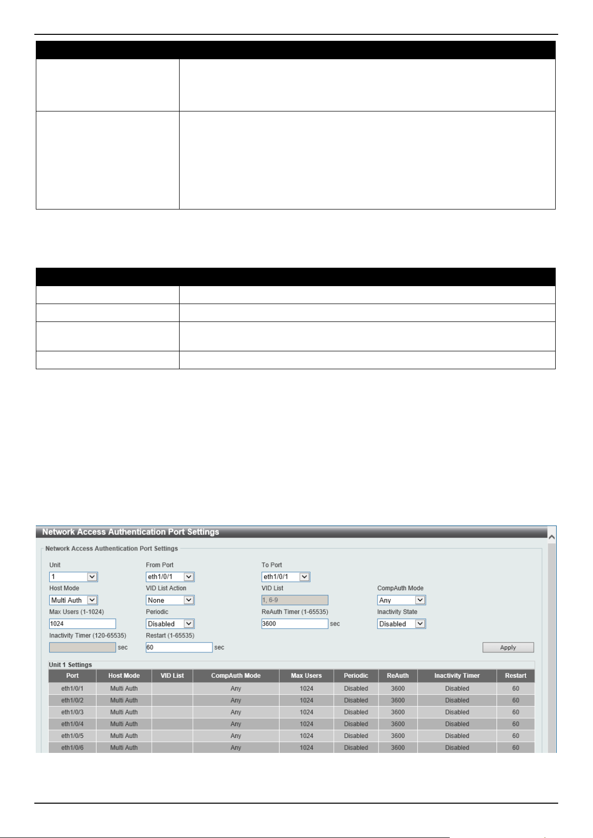
DGS-1520 Series Gigabit Ethernet Smart Managed Switch Web UI Reference Guide
468
Parameter Description
then the station is directly moved to the new port. The session with the original port
is removed. The authenticated host on port 1 can be moved to port 2.
If this feature is disabled and an authenticated host moves to another port, then
this is treated as a violation error.
Authorization State
Select to enable or disable the authorized state here. The option is used to enable
or disable the acceptance of an authorized configuration. When authorization is
enabled for authentication, the authorized attributes (for example VLAN, 802.1p
default priority, bandwidth, and ACL) assigned by the RADIUS server will be
accepted if the authorization status is enabled. Bandwidth and ACL are assigned
on a per-port basis. If in the multi-authenticated mode, VLAN and 802.1p are
assigned on a per-host basis. Otherwise, Bandwidth and ACL are assigned on a
per-port basis.
Click the Apply button to accept the changes made.
The fields that can be configured in User Information are described below:
Parameter Description
User Name
Enter the user name used here. This name can be up to 32 characters long.
VID
Enter the VLAN ID used here.
Password Type Select the password type option here. Options to choose from are Plain Text and
Encrypted.
Password
Enter the password used here.
Click the Apply button to accept the changes made.
Click the Delete button to remove the specified entry.
Network Access Authentication Port Settings
This window is used to display and configure the network access authentication port settings.
To view the following window, click Security > Network Access Authentication > Network Access Authentication
Port Settings, as shown below:
Figure 9-80 Network Access Authentication Port Settings Window

DGS-1520 Series Gigabit Ethernet Smart Managed Switch Web UI Reference Guide
469
The fields that can be configured are described below:
Parameter Description
Unit
Select the Switch unit that will be used for this configuration here.
From Port - To Port
Select the appropriate port range used for the configuration here.
Host Mode
Select the host mode option that will be associated with the selected port(s) here.
Options to choose from are Multi Host and Multi Auth. If the port is operated in
the multi-host mode, and if one of the hosts is authenticated, then all other hosts
are allowed to access the port. According to 802.1X authentication, if the re-
authentication fails or the authenticated user logs off, the port will be blocked for a
quiet period. The port restores the processing of EAPOL packets after the quiet
period. If the port is operated in the multi-authenticated mode, then each host
needs to be authenticated individually to access the port. A host is represented by
its MAC address. Only the authorized host is allowed to access.
VID List Action Select the VID list action here. Options to choose from are None, Add, and
Delete.
VID List After selecting the Multi Auth option as the Host Mode, the following parameter is
available. Enter the VLAN ID used here. This is useful when different VLANs on
the Switch have different authentication requirements. After the client is
authenticated, the client will not be re-authenticated when received from other
VLANs. This option is useful for trunk ports to do per-VLAN authentication control.
When a port's authentication mode is changed to multi-host, the previous
authentication VLAN(s) on this port will be cleared.
CompAuth Mode
Select the compound authentication mode option here. Options to choose from
are:
• Any - Specifies that if any of the authentication method (802.1X, MAC-
based Access Control or WAC) to passes, then pass.
• MAC-WAC - Specifies to verify MAC-based authentication first. If the client
passes, WAC will be verified next. Both authentication methods need to be
passed.
Max Users
Enter the maximum users value used here. This value must be between 1 and
1024.
Periodic
Select to enable or disable periodic re-authentication for the selected port here.
This parameter only affects the 802.1X protocol.
ReAuth Timer
Enter the re-authentication timer value here. This value must be between 1 and
65535 seconds. By default, this value is 3600 seconds.
Inactivity State
Select to enable or disable the inactivity state here.
Inactivity Timer When the Inactivity State is enabled, enter the inactivity timer value here. This
value must be between 120 and 65535 seconds. This parameter only affects the
WAC authentication protocol.
Restart
Enter the restart time value used here. This value must be between 1 and 65535
seconds.
Click the Apply button to accept the changes made.
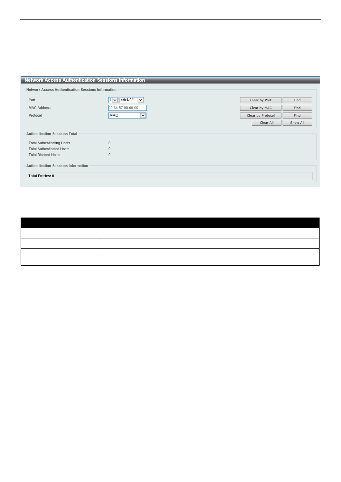
DGS-1520 Series Gigabit Ethernet Smart Managed Switch Web UI Reference Guide
470
Network Access Authentication Sessions Information
This window is used to view and clear the network access authentication session information.
To view the following window, click Security > Network Access Authentication > Network Access Authentication
Sessions Information, as shown below:
Figure 9-81 Network Access Authentication Sessions Information Window
The fields that can be configured are described below:
Parameter Description
Port
Select the appropriate Switch unit and port used for the query here.
MAC Address
Enter the MAC address used here.
Protocol Select the protocol option used here. Options to choose from are MAC, WAC, and
DOT1X.
Click the Clear by Port button to the clear the information based on the port selected.
Click the Clear by MAC button to the clear the information based on the MAC address entered.
Click the Clear by Protocol button to the clear the information based on the protocol selected.
Click the Clear All button to clear all the information in this table.
Click the Find button to locate a specific entry based on the information entered.
Click the Show All button to locate and display all the entries.
Safeguard Engine
Periodically, malicious hosts on the network will attack the Switch by utilizing packet flooding (ARP Storm) or other
methods. These attacks may increase the Switch's CPU load beyond its capability. To alleviate this problem, the
Safeguard Engine function was added to the Switch's software.
The Safeguard Engine can help the overall operability of the Switch by minimizing the workload of the Switch while the
attack is ongoing, thus making it capable to forward essential packets over its network in a limited bandwidth.
If the CPU load rises above the rising threshold value, the Safeguard Engine function will be activated and the Switch
will enter the exhausted mode. In the exhausted mode, the Switch will limit the bandwidth available for ARP and
broadcast IP packets. If the CPU load falls below the falling threshold value, the Safeguard Engine will be deactivated
and the Switch will exit the exhausted mode and enter the normal mode.

DGS-1520 Series Gigabit Ethernet Smart Managed Switch Web UI Reference Guide
471
Packets that are destined to the CPU can be classified into three groups. These groups, otherwise known as sub-
interfaces, are logical interfaces that the CPU will use to identify certain types of traffic. The three groups are
Protocol, Manage, and Route. Generally, the Protocol group should receive the highest priority when the Switch's
CPU processes received packets and the Route group should receive the lowest priority as the Switch's CPU usually
does get involved in the processing of routing packets. In the Protocol group, packets are protocol control packets
identified by the router. In the Manage group, packets are destined to any router or system network management
interface by means of interactive access protocols, like Telnet and SSH. In the Route group, packets are identified as
traversing routing packets that is generally processed by the router CPU.
In the following table a list of supported protocols are displayed with their respective sub-interfaces (groups):
Protocol Name Sub-interface (Group) Description
802.1X
Protocol Port-based Network Access Control
ARP
Protocol Address resolution Protocol
DHCP
Protocol Dynamic Host Configuration Protocol
DNS
Protocol Domain Name System
DVMRP
Protocol Distance Vector Multicast Routing Protocol
GVRP
Protocol GARP VLAN Registration Protocol
ICMPv4
Protocol Internet Control Message Protocol
ICMPv6-
Neighbor
Protocol IPv6 Internet Control Message Protocol Neighbor Discovery
Protocol (NS/NA/RS/RA)
ICMPv6-Other
Protocol IPv6 Internet Control Message Protocol except Neighbor Discovery
Protocol (NS/NA/RS/RA)
IGMP
Protocol Internet Group Management Protocol
LACP
Protocol Link Aggregation Control Protocol
NTP
Protocol Network Time Protocol
OSPF
Protocol Open Shortest Path First
PIM
Protocol Protocol Independent Multicast
RIP
Protocol Routing Information Protocol
SNMP
Manage Simple Network Management Protocol
SSH
Manage Secure Shell
STP
Protocol Spanning Tree Protocol
Telnet
Manage Telnet
TFTP
Manage Trivial File Transfer Protocol
VRRP
Protocol Virtual Router Redundancy Protocol
Web
Manage Hypertext Transfer Protocol (HTTP) and Hypertext Transfer
Protocol Secure (HTTPS)
A customized rate limit (in packets per second) can be assigned to the Safeguard Engine's sub-interfaces as a whole
or to individual protocols specified by the user in the management interface. Be careful when customizing the rate limit
for individual protocols, using this function, as improper rate limits can cause the Switch to process packets
abnormally.
NOTE: When Safeguard Engine is enabled, the Switch will allot bandwidth to various traffic flows
(ARP, IP) using the FFP (Fast Filter Processor) metering table to control the CPU utilization
and limit traffic. This may limit the speed of routing traffic over the network.
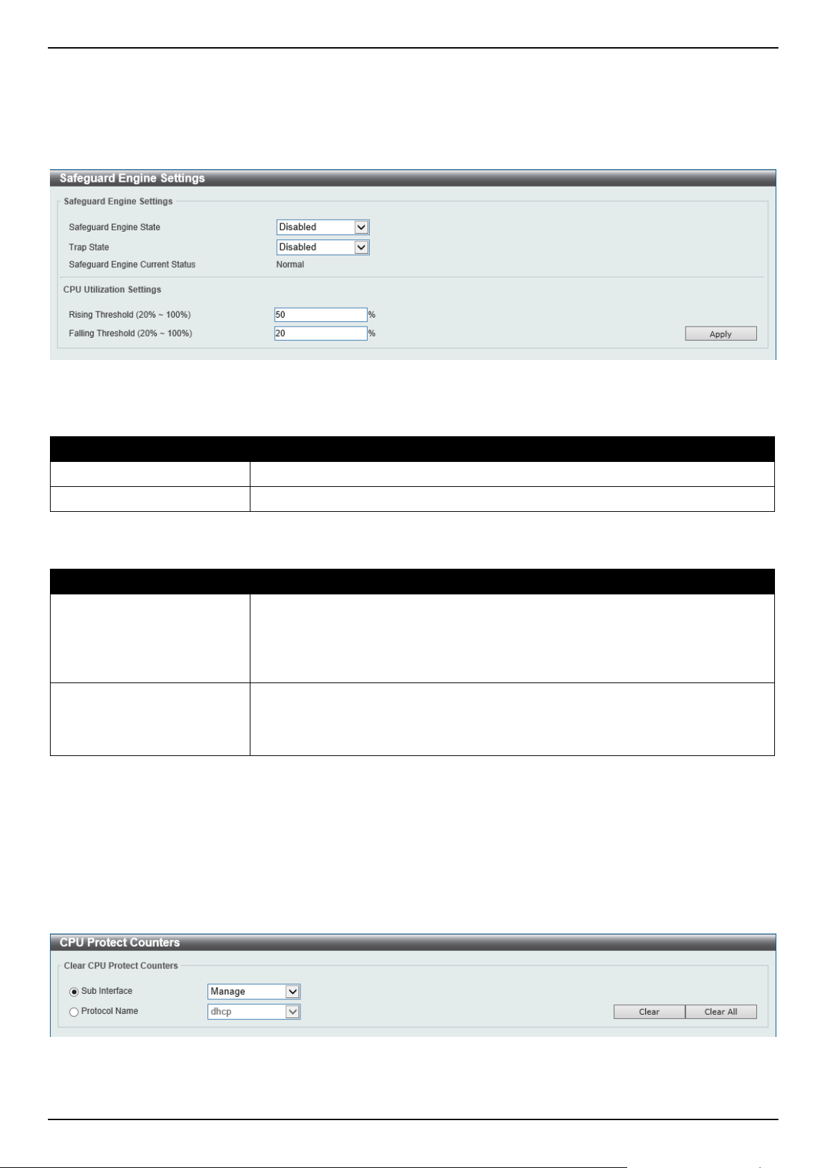
DGS-1520 Series Gigabit Ethernet Smart Managed Switch Web UI Reference Guide
472
Safeguard Engine Settings
This window is used to display and configure the safeguard engine settings.
To view the following window, click Security > Safeguard Engine > Safeguard Engine Settings, as shown below:
Figure 9-82 Safeguard Engine Settings Window
The fields that can be configured in Safeguard Engine Settings are described below:
Parameter Description
Safeguard Engine State
Select to enable or disable the safeguard engine feature here.
Trap State
Select to enable or disable the safeguard engine trap state here.
The fields that can be configured in CPU Utilization Settings are described below:
Parameter Description
Rising Threshold
Enter the rising threshold value here. This value must be between 20% and 100%.
This value is used to configure the acceptable level of CPU utilization before the
Safeguard Engine mechanism is enabled. Once the CPU utilization reaches this
percentage level, the Switch will move into Exhausted mode, based on the
parameters provided in this window.
Falling Threshold
Enter the falling threshold value here. This value must be between 20% and 100%.
This value is used to configure the acceptable level of CPU utilization as a
percentage, where the Switch leaves the Safeguard Engine state and returns to
normal mode.
Click the Apply button to accept the changes made.
CPU Protect Counters
This window is used to view and clear the CPU protection counter information.
To view the following window, click Security > Safeguard Engine > CPU Protect Counters, as shown below:
Figure 9-83 CPU Protect Counters Window
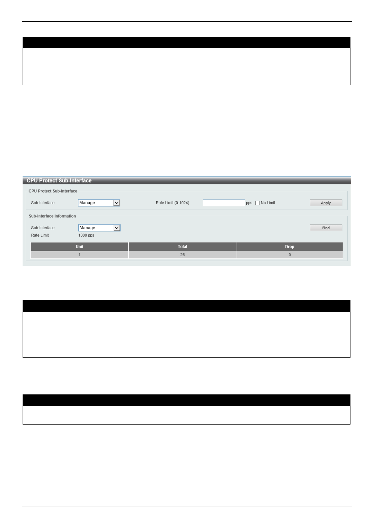
DGS-1520 Series Gigabit Ethernet Smart Managed Switch Web UI Reference Guide
473
The fields that can be configured are described below:
Parameter Description
Sub Interface Select the sub-interface option here. Options to choose from are Manage,
Protocol, Route, and All. This option specifies to clear the CPU protect related
counters of sub-interfaces.
Protocol Name
Select the protocol name option here.
Click the Clear button to clear the information based on the selections made.
Click the Clear All button to clear all the information in this table.
CPU Protect Sub-Interface
This window is used to display and configure the CPU protection sub-interface settings.
To view the following window, click Security > Safeguard Engine > CPU Protect Sub-Interface, as shown below:
Figure 9-84 CPU Protect Sub-Interface Window
The fields that can be configured in CPU Protect Sub-Interface are described below:
Parameter Description
Sub-Interface Select the sub-interface option here. Options to choose from are Manage,
Protocol, and Route.
Rate Limit
Enter the rate limit value used here. This value must be between 0 and 1024
packets per second.
Tick the No Limit option to disable the rate limit.
Click the Apply button to accept the changes made.
The fields that can be configured in Sub-Interface Information are described below:
Parameter Description
Sub-Interface Select the sub-interface option here. Options to choose from are Manage,
Protocol, and Route.
Click the Find button to locate a specific entry based on the information entered.
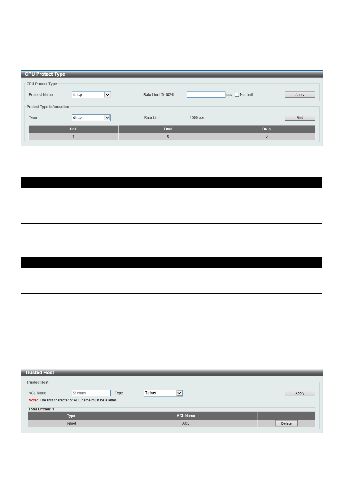
DGS-1520 Series Gigabit Ethernet Smart Managed Switch Web UI Reference Guide
474
CPU Protect Type
This window is used to display and configure the CPU protection type settings.
To view the following window, click Security > Safeguard Engine > CPU Protect Type, as shown below:
Figure 9-85 CPU Protect Type Window
The fields that can be configured in CPU Protect Type are described below:
Parameter Description
Protocol Name
Select the protocol name option here.
Rate Limit
Enter the rate limit value used here. This value must be between 0 and 1024
packets per second.
Tick the No Limit option to disable the rate limit.
Click the Apply button to accept the changes made.
The fields that can be configured in Protect Type Information are described below:
Parameter Description
Type Select the protocol type here. After selecting the protocol type, the Rate Limit
assigned to the protocol type will be displayed.
Select the Unit option to specify the unit ID of the Switch in the physical stack.
Click the Find button to locate a specific entry based on the information entered.
Trusted Host
This window is used to display and configure the trusted host settings.
To view the following window, click Security > Trusted Host, as shown below:
Figure 9-86 Trusted Host Window
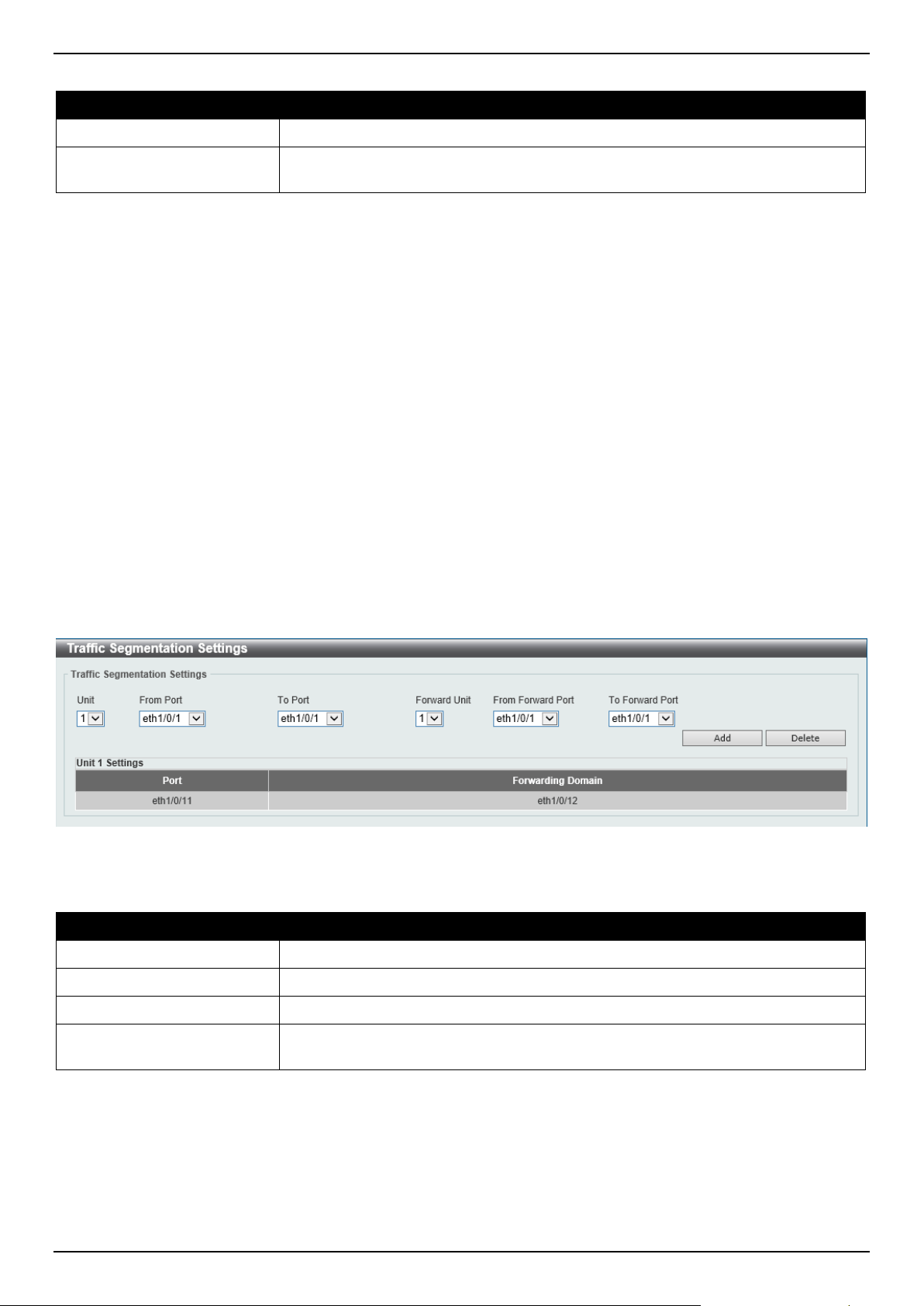
DGS-1520 Series Gigabit Ethernet Smart Managed Switch Web UI Reference Guide
475
The fields that can be configured are described below:
Parameter Description
ACL Name
Enter the access class' name here. This name can be up to 32 characters long.
Type Select the trusted host type here. Options to choose from are Telnet, SSH, Ping,
HTTP, and HTTPS.
Click the Apply button to accept the changes made.
Click the Delete button to remove the specific entry.
Traffic Segmentation Settings
This window is used to display and configure the traffic segmentation settings. When the traffic segmentation
forwarding domain is specified, packets received by the port will be restricted in Layer 2 packet forwarding to
interfaces within the domain. When the forwarding domain of a port is empty, Layer 2 forwarding for packets received
by the port is not restricted.
The traffic segmentation member list can be comprised of different interface types, for example port and port-channel
in the same forwarding domain. If the interfaces specified by the command include a port-channel, all the member
ports of this port-channel will be included in the forwarding domain.
If the forwarding domain of an interface is empty, then there is no restriction on Layer 2 forwarding of packets received
by the port.
To view the following window, click Security > Traffic Segmentation Settings, as shown below:
Figure 9-87 Traffic Segmentation Settings Window
The fields that can be configured are described below:
Parameter Description
Unit
Select the receiving Switch unit that will be used for this configuration here.
From Port - To Port
Select the receiving port range used for the configuration here.
Forward Unit
Select the forward Switch unit that will be used for this configuration here.
From Forward Port ~ To
Forward Port
Select the forward port range used for the configuration here.
Click the Add button to add a new entry based on the information entered.
Click the Delete button to remove an entry based on the information entered.
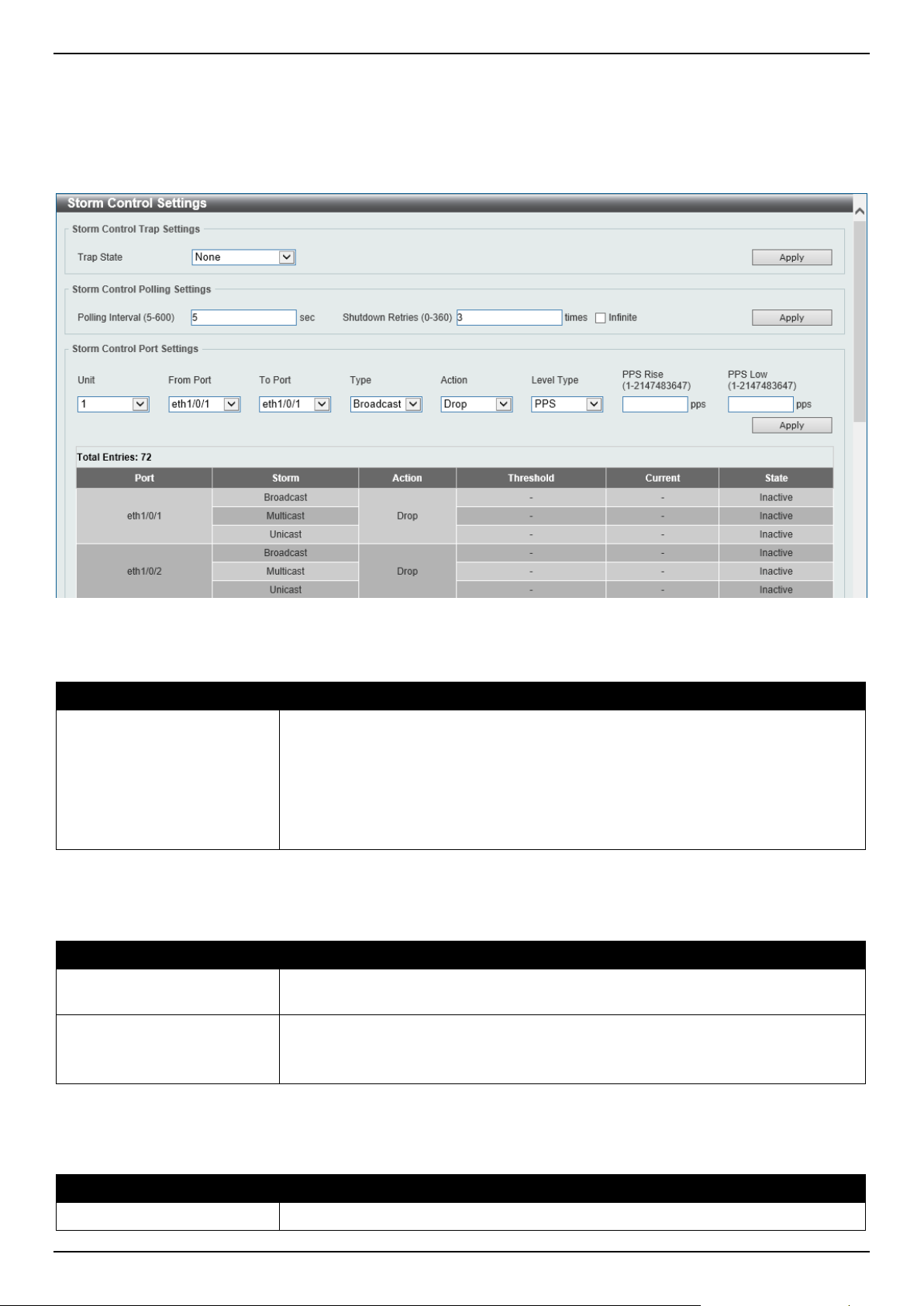
DGS-1520 Series Gigabit Ethernet Smart Managed Switch Web UI Reference Guide
476
Storm Control Settings
This window is used to display and configure the storm control settings.
To view the following window, click Security > Storm Control Settings, as shown below:
Figure 9-88 Storm Control Settings Window
The fields that can be configured in Storm Control Trap Settings are described below:
Parameter Description
Trap State
Select the storm control trap option here. Options to choose from are:
• None - No traps are sent.
• Storm Occur - A trap notification is sent when a storm event is detected.
• Storm Clear - A trap notification is sent when a storm event is cleared.
• Both - A trap notification is sent when a storm event is detected and
cleared.
Click the Apply button to accept the changes made.
The fields that can be configured in Storm Control Polling Settings are described below:
Parameter Description
Polling Interval
Enter the interval value used here. This value must be between 5 and 600
seconds. By default, this value is 5 seconds.
Shutdown Retries
Enter the shutdown retries value used here. This value must be between 0 and
360. By default, this value is 3.
Tick the Infinite option to disable this feature.
Click the Apply button to accept the changes made.
The fields that can be configured in Storm Control Port Settings are described below:
Parameter Description
Unit
Select the Switch unit that will be used for this configuration here.
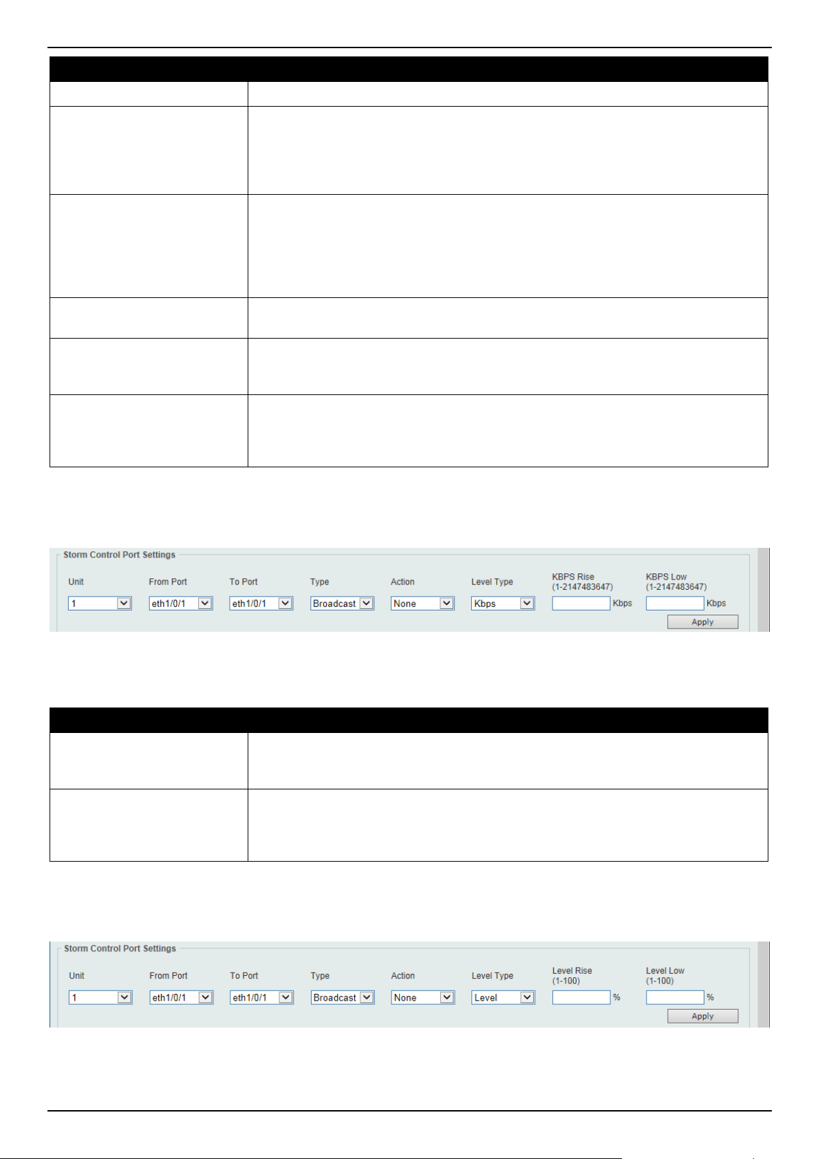
DGS-1520 Series Gigabit Ethernet Smart Managed Switch Web UI Reference Guide
477
Parameter Description
From Port - To Port
Select the appropriate port range used for the configuration here.
Type
Select the type of storm attack that will be controlled here. Options to choose from
are Broadcast, Multicast, and Unicast. When the action is configured as the
shutdown mode, the unicast refers to both known and unknown unicast packets;
that is, if the known and unknown unicast packets hit the specified threshold, the
port will be shutdown. Otherwise, unicast refers to unknown unicast packets.
Action
Select the action that will be taken here. Options to choose from are:
• None - Specifies not to filter the storm packets.
• Shutdown - Specifies to shut down the port when the value specified for
rise threshold is reached.
• Drop - Specifies to discards packets that exceed the risen threshold.
Level Type Select the level type option here. Options to choose from are PPS, Kbps, and
Level.
PPS Rise
Enter the rise packets per second value here. This option specifies the rise
threshold value in packets count per second. This value must be between 1 and
2147483647 packets per second.
PPS Low
Enter the low packets per second value here. This option specifies the low
threshold value in packets count per second. This value must be between 1 and
2147483647 packets per second. By default, this is 80% of the specified PPS Rise
value.
Click the Apply button to accept the changes made.
After selecting the Kbps option as the Level Type, the following parameters are available.
Figure 9-89 Storm Control Settings (Level Type - Kbps) Window
The additional fields that can be configured in Storm Control Port Settings are described below:
Parameter Description
KBPS Rise
Enter the rise KBPS value used here. This option specifies the rise threshold value
as a rate of kilobits per second at which traffic is received on the port. This value
must be between 1 and 2147483647 Kbps.
KBPS Low
Enter the low KBPS value used here. This option specifies the low threshold value
as a rate of kilobits per second at which traffic is received on the port. This value
must be between 1 and 2147483647 Kbps. By default, this is 80% of the specified
KBPS Rise value.
Click the Apply button to accept the changes made.
After selecting the Level option as the Level Type, the following parameters are available.
Figure 9-90 Storm Control Settings (Level Type - Level) Window

DGS-1520 Series Gigabit Ethernet Smart Managed Switch Web UI Reference Guide
478
The additional fields that can be configured in Storm Control Port Settings are described below:
Parameter Description
Level Rise
Enter the rise level value used here. This option specifies the rise threshold value
as a percentage of the total bandwidth per port at which traffic is received on the
port. This value must be between 1% and 100%.
Level Low
Enter the low-level value used here. This option specifies the low threshold value
as a percentage of the total bandwidth per port at which traffic is received on the
port. This value must be between 1% and 100%. By default, this is 80% of the
Level Rise value.
Click the Apply button to accept the changes made.
DoS Attack Prevention Settings
This window is used to display and configure the Denial-of-Service (DoS) attack prevention settings. The following
well-known DoS types, which can be detected by most Switches:
• Land Attack: This type of attack involves IP packets where the source and destination address are set to the
address of the target device. It may cause the target device to reply to itself continuously.
• Blat Attack: This type of attack will send packets with the TCP/UDP source port equal to the destination port of
the target device. It may cause the target device to respond to itself.
• TCP-Null: This type of attack involves port scanning by using specific packets, which contain a sequence
number of 0 and no flags.
• TCP-Xmas: This type of attack involves port scanning by using specific packets, which contain a sequence
number of 0 and the Urgent (URG), Push (PSH), and FIN flags.
• TCP SYN-FIN: This type of attack involves port scanning by using specific packets, which contain SYN and FIN
flags.
• TCP SYN SrcPort Less 1024: This type of attack involves port scanning by using specific packets, which
contain source port 0 to 1023, and SYN flag.
• Ping of Death Attack: A ping of death is a type of attack on a computer that involves sending a malformed or
otherwise a malicious ping to a computer. A ping is normally 64 bytes in size (many computers cannot handle a
ping larger than the maximum IP packet size which is 65535 bytes). The sending of a ping of this size can crash
the target computer. Traditionally, this bug has been relatively easy to exploit. Generally, sending a 65536 byte
ping packet is illegal according to networking protocol, but a packet of such a size can be sent if it is
fragmented; when the target computer reassembles the packet, a buffer overflow can occur, which often causes
a system crash.
• TCP Tiny Fragment Attack: The Tiny TCP Fragment attacker uses IP fragmentation to create extremely small
fragments and force the TCP header information into a separate packet fragment to pass through the check
function of the router and issue an attack.
• All Types: All of above types.
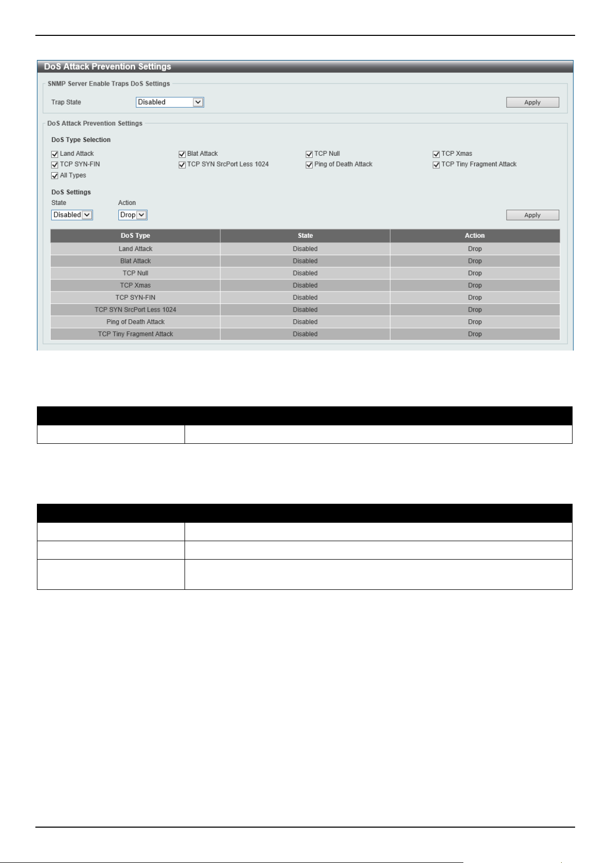
DGS-1520 Series Gigabit Ethernet Smart Managed Switch Web UI Reference Guide
479
To view the following window, click Security > DoS Attack Prevention Settings, as shown below:
Figure 9-91 DoS Attack Prevention Settings Window
The fields that can be configured in SNMP Server Enable Traps DoS Settings are described below:
Parameter Description
Trap State
Select to enable or disable the DoS attack prevention trap state here.
Click the Apply button to accept the changes made.
The fields that can be configured in DoS Attack Prevention Settings are described below:
Parameter Description
DoS Type Selection
Tick the DoS type option that will be prevented here.
State
Select to enable or disable the global DoS attack prevention state here.
Action
Select the action that will be taken when the DoS attack was detected here. The
only option to select here is Drop.
Click the Apply button to accept the changes made.
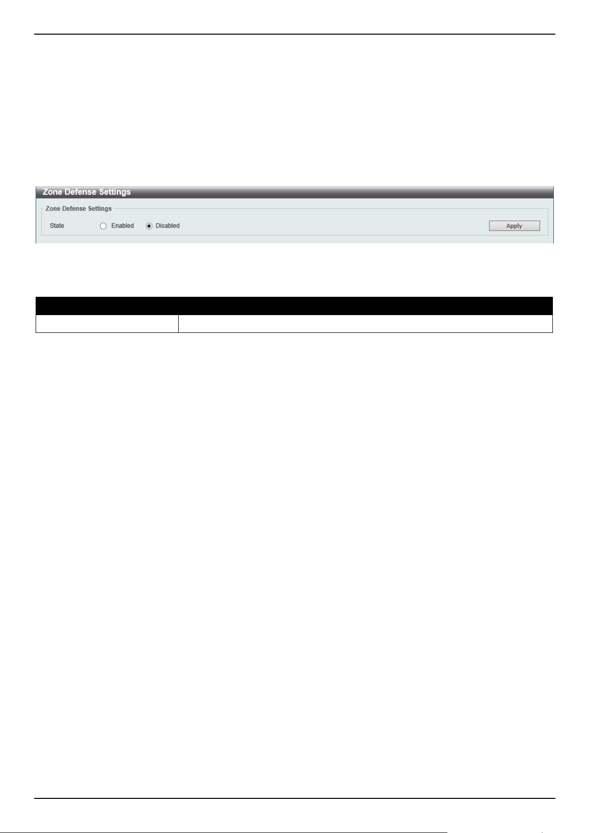
DGS-1520 Series Gigabit Ethernet Smart Managed Switch Web UI Reference Guide
480
Zone Defense Settings
This window is used to display and configure the Zone Defense settings. When Zone Defense is enabled, the ACL
resources will be reserved for Zone Defense. If the Switch does not have enough ACL resources for Zone Defense, it
cannot be enabled.
Zone Defense is triggered when abnormal network traffic conditions meet pre-configured thresholds on the firewall.
When this happens, the firewall immediately and automatically contacts the Switch and issues commands to them,
which result in blocking any traffic to and from the suspicious host.
To view the following window, click Security > Zone Defense Settings, as shown below:
Figure 9-92 Zone Defense Settings Window
The fields that can be configured are described below:
Parameter Description
State
Select to enable or disable the Zone Defense function here.
Click the Apply button to accept the changes made.
SSH
Secure Shell (SSH) is a program allowing secure remote login and secure network services over an insecure network
that allows a secure login to remote host computers, a safe method of executing commands on a remote end node,
and will provide secure encrypted and authenticated communication between two non-trusted hosts. SSH, with its
array of unmatched security features is an essential tool in today's networking environment. It is a powerful guardian
against numerous existing security hazards that now threaten network communications.
The steps required to use the SSH protocol for secure communication between a remote PC (the SSH client) and the
Switch (the SSH server) are as follows:
• Create a user account with admin-level access using the User Accounts window. This is identical to creating
any other admin-level User Account on the Switch, including specifying a password. This password is used to
logon to the Switch, once a secure communication path has been established using the SSH protocol.
• Configure the User Account to use a specified authorization method to identify users that are allowed to
establish SSH connections with the Switch using the SSH User Authentication Mode window. There are three
choices as to the method SSH will use to authorize the user, which are Host Based, Password, and Public Key.
• Configure the encryption algorithm that SSH will use to encrypt and decrypt messages sent between the SSH
client and the SSH server, using the SSH Authentication Method and Algorithm Settings window.
• Finally, enable SSH on the Switch using the SSH Configuration window.
After completing the preceding steps, a SSH Client on a remote PC can be configured to manage the Switch using a
secure, in band connection.
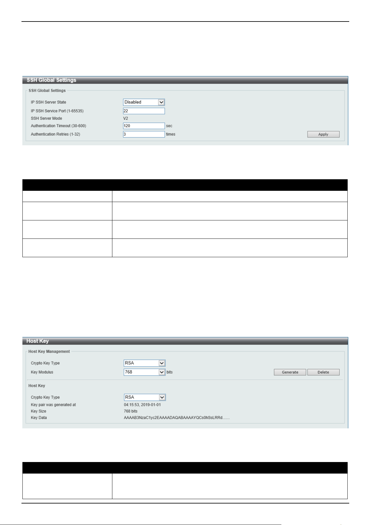
DGS-1520 Series Gigabit Ethernet Smart Managed Switch Web UI Reference Guide
481
SSH Global Settings
This window is used to display and configure the global SSH settings.
To view the following window, click Security > SSH > SSH Global Settings, as shown below:
Figure 9-93 SSH Global Settings Window
The fields that can be configured are described below:
Parameter Description
IP SSH Server State
Select to enable or disable the global SSH server state.
IP SSH Service Port
Enter the SSH service port number used here. This value must be between 1 and
65535. By default, this value is 22.
Authentication Timeout
Enter the authentication timeout value here. This value must be between 30 and
600 seconds. By default, this value is 120 seconds.
Authentication Retries
Enter the authentication retries value here. This value must be between 1 and 32.
By default, this value is 3.
Click the Apply button to accept the changes made.
Host Key
This window is used to view and generate the SSH host key.
To view the following window, click Security > SSH > Host Key, as shown below:
Figure 9-94 Host Key Window
The fields that can be configured in Host Key Management are described below:
Parameter Description
Crypto Key Type
Select the crypto key type used here. Options to choose from are the Rivest
Shamir Adleman (RSA) key type and the Digital Signature Algorithm (DSA) key
type.
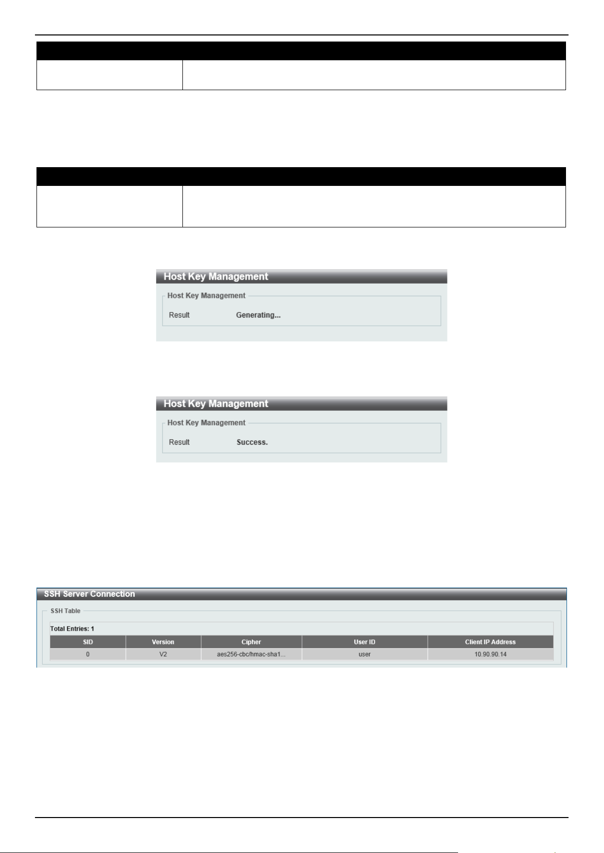
DGS-1520 Series Gigabit Ethernet Smart Managed Switch Web UI Reference Guide
482
Parameter Description
Key Modulus Select the key modulus value here. Options to choose from are 360, 512, 768,
1024, and 2048 bit.
Click the Generate button to generate a host key based on the selections made.
Click the Delete button to remove a host key based on the selections made.
The fields that can be configured in Host Key are described below:
Parameter Description
Crypto Key Type
Select the crypto key type used here. Options to choose from are the Rivest
Shamir Adleman (RSA) key type and the Digital Signature Algorithm (DSA) key
type.
After clicking the Generate button, the following window will appear:
Figure 9-95 Host Key (Generating) Window
After the key was successfully generated, the following window will appear.
Figure 9-96 Host Key (Generating, Success) Window
SSH Server Connection
This window is used to view the SSH server connections table.
To view the following window, click Security > SSH > SSH Server Connection, as shown below:
Figure 9-97 SSH Server Connection Window
SSH User Settings
This window is used to display and configure the SSH user settings.
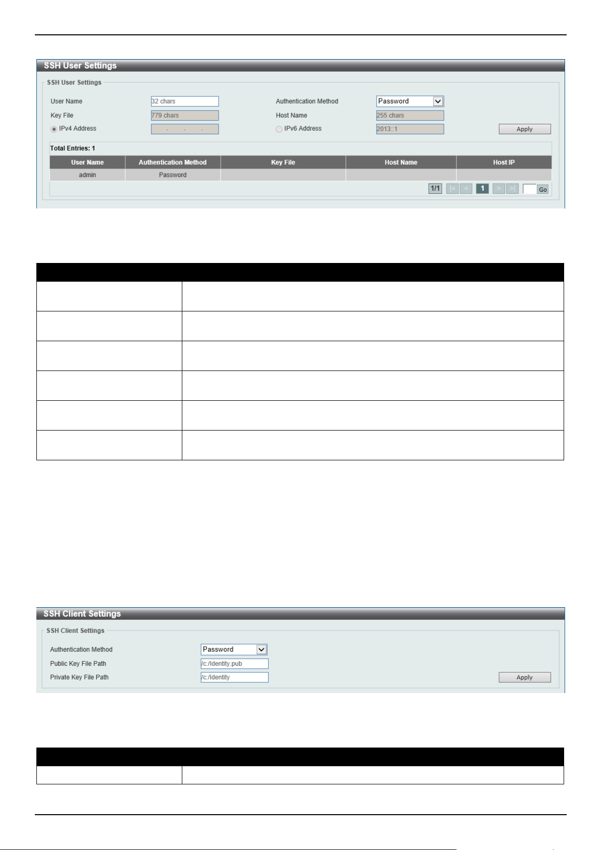
DGS-1520 Series Gigabit Ethernet Smart Managed Switch Web UI Reference Guide
483
To view the following window, click Security > SSH > SSH User Settings, as shown below:
Figure 9-98 SSH User Settings Window
The fields that can be configured are described below:
Parameter Description
User Name
Enter the SSH user's username used here. This name can be up to 32 characters
long.
Authentication Method
Select the authentication methods used here. Options to choose from are
Password, Public Key, and Host-based.
Key File After selecting the Public Key or Host-based option as the Authentication
Method, enter the public key here.
Host Name After selecting the Host-based option as the Authentication Method, enter the
host name here.
IPv4 Address After selecting the Host-based option as the Authentication Method, select and
enter the IPv4 address here.
IPv6 Address After selecting the Host-based option as the Authentication Method, select and
enter the IPv6 address here.
Click the Apply button to accept the changes made.
Enter a page number and click the Go button to navigate to a specific page when multiple pages exist.
SSH Client Settings
This window is used to display and configure the SSH client settings.
To view the following window, click Security > SSH > SSH Client Settings, as shown below:
Figure 9-99 SSH Client Settings Window
The fields that can be configured are described below:
Parameter Description
Authentication Method
Select the authentication method here. Options to choose from are:

DGS-1520 Series Gigabit Ethernet Smart Managed Switch Web UI Reference Guide
484
Parameter Description
• Password - Specifies to use the password authentication method for this
user account.
• Public Key - Specifies to use the public key authentication method for this
user account. Enter the URL of a local file to be used as the public key of
this user.
By default, the Password option is used.
Public Key File Path
Enter the path and filename of the local file to be used as the public key here.
Private Key File Path
Enter the path of the local file to be used as the private key here.
Click the Apply button to accept the changes made.
SSL
Secure Sockets Layer (SSL) is a security feature that will provide a secure communication path between a server and
client through the use of authentication, digital signatures, and encryption. These security functions are implemented
through the use of a cipher suite, which is a security string that determines the exact cryptographic parameters,
specific encryption algorithms, and key sizes to be used for an authentication session and consists of three levels:
• Key Exchange: The first part of the cipher suite string specifies the public key algorithm to be used. This
Switch utilizes the Rivest Shamir Adleman (RSA) public key algorithm and the Digital Signature Algorithm
(DSA), specified here as the DHE DSS Diffie-Hellman (DHE) public key algorithm. This is the first authentication
process between client and server as they "exchange keys" in looking for a match and therefore authentication
to be accepted to negotiate encryptions on the following level.
• Encryption: The second part of the cipher suite that includes the encryption used for encrypting the messages
sent between client and host. The Switch supports two types of cryptology algorithms:
o Stream Ciphers - There are two types of stream ciphers on the Switch, RC4 with 40-bit keys, and RC4
with 128-bit keys. These keys are used to encrypt messages and need to be consistent between client
and host for optimal use.
o CBC Block Ciphers - CBC refers to Cipher Block Chaining, which means that a portion of the
previously encrypted block of encrypted text is used in the encryption of the current block. The Switch
supports the 3DES EDE encryption code defined by the Data Encryption Standard (DES) and the
Advanced Encryption Standard (AES) to create the encrypted text.
• Hash Algorithm: This part of the cipher suite allows the user to choose a message digest function, which will
determine a Message Authentication Code. This Message Authentication Code will be encrypted with a sent
message to provide integrity and prevent against replay attacks. The Switch supports three hash algorithms,
MD5 (Message Digest 5), SHA (Secure Hash Algorithm), and SHA256.
These three parameters are uniquely assembled in four choices on the Switch to create a three-layered encryption
code for secure communication between the server and the client. The user may implement any one or combination of
the cipher suites available, yet different cipher suites will affect the security level and the performance of the secured
connection. The information included in the cipher suites is not included with the Switch and requires downloading
from a third source in a file form called a certificate. This function of the Switch cannot be executed without the
presence and implementation of the certificate file and can be downloaded to the Switch by utilizing a TFTP server or
the Switch file system. The Switch supports TLS 1.0, TLS 1.1, and TLS 1.2. Other versions of SSL may not be
compatible with this Switch and may cause problems upon authentication and transfer of messages from client to
server.
When the SSL function has been enabled, the web will become disabled. To manage the Switch through the web-
based management while utilizing the SSL function, the web browser must support SSL encryption and the header of
the URL must begin with https:// (Ex. https://xx.xx.xx.xx). Any other method will result in an error and no access can
be authorized for the web-based management.
Users can download a certificate file for the SSL function on the Switch from a TFTP server. The certificate file is a
data record used for authenticating devices on the network. It contains information on the owner, keys for
authentication and digital signatures. Both the server and the client must have consistent certificate files for optimal
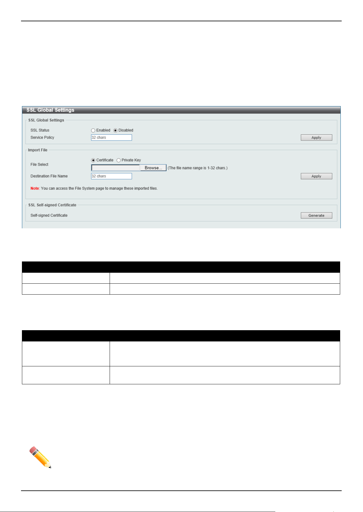
DGS-1520 Series Gigabit Ethernet Smart Managed Switch Web UI Reference Guide
485
use of the SSL function. Currently, the Switch comes with a certificate pre-loaded though the user may need to
download more, depending on user circumstances.
SSL Global Settings
This window is used to display and configure the global SSL settings.
To view the following window, click Security > SSL > SSL Global Settings, as shown below:
Figure 9-100 SSL Global Settings Window
The fields that can be configured in SSL Global Settings are described below:
Parameter Description
SSL Status
Select to enable or disable the global SSL status here.
Service Policy
Enter the service policy name here. This name can be up to 32 characters long.
Click the Apply button to accept the changes made.
The fields that can be configured in Import File are described below:
Parameter Description
File Select Select the file type that will be loaded here. Options to choose from are Certificate
and Private Key. After selecting the file type, browse to the appropriate file,
located on the local computer, by pressing the Browse button.
Destination File Name
Enter the destination file name used here. This name can be up to 32 characters
long.
Click the Apply button to accept the changes made.
Click the Generate button in the SSL-Self-signed Certificate section to generate a new self-signed certificate,
regardless if there is a built-in self-signed certificate or not. The certificate generated does not affect the user-
downloaded certificates.
NOTE: The SSL self-signed certificate only supports self-signature RSA certificates with a key length
of 2048 bits.
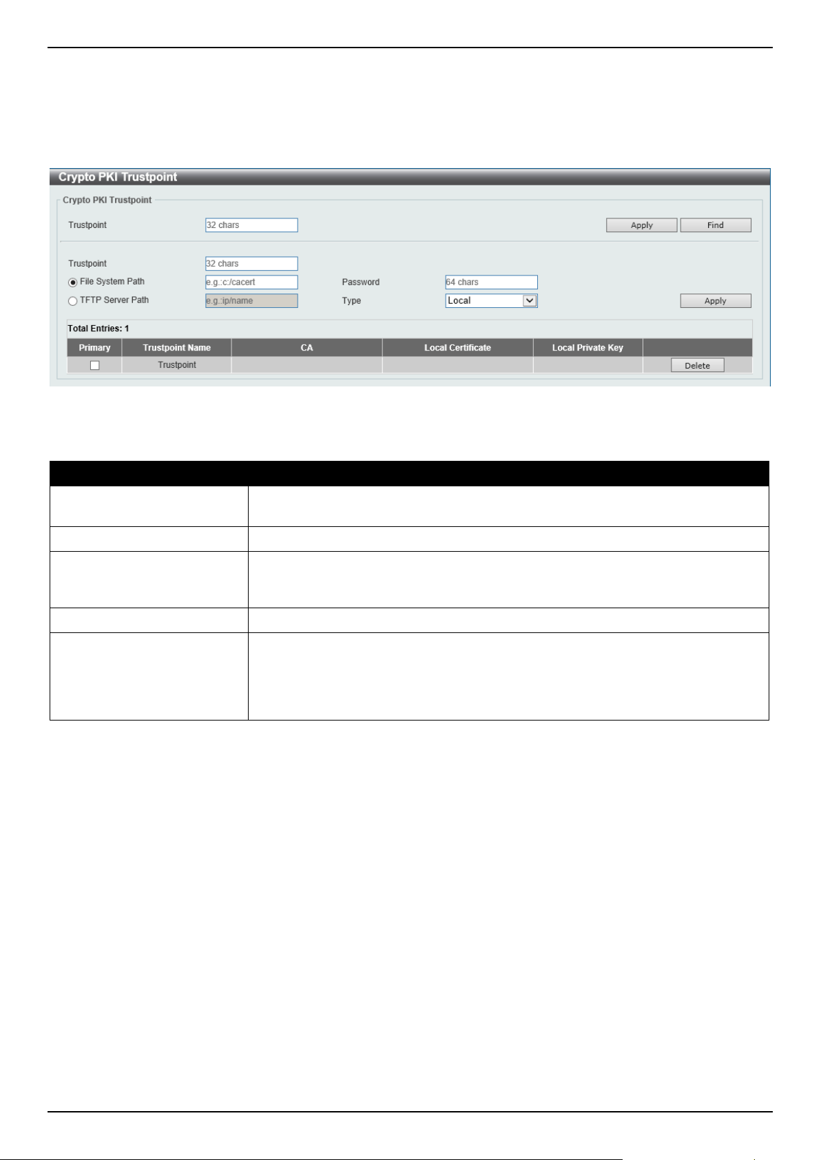
DGS-1520 Series Gigabit Ethernet Smart Managed Switch Web UI Reference Guide
486
Crypto PKI Trustpoint
This window is used to display and configure the crypto PKI trust point settings.
To view the following window, click Security > SSL > Crypto PKI Trustpoint, as shown below:
Figure 9-101 Crypto PKI Trustpoint Window
The fields that can be configured are described below:
Parameter Description
Trustpoint
Enter the name of the trust-point that is associated with the imported certificates
and key pairs here. This name can be up to 32 characters long.
File System Path
Enter the file system path for certificates and key pairs here.
Password
Enter the encrypted password phrase that is used to undo encryption when the
private keys are imported here. The password phrase is a string of up to 64
characters. If the password phrase is not specified, the NULL string will be used.
TFTP Server Path
Enter the TFTP server path here.
Type
Select the type of certificate that will be imported here. Options to choose from are:
• Both - Specifies to import the CA certificate, local certificate, and key pairs.
• CA - Specifies to import the CA certificate only.
• Local - Specifies to import local certificate and key pairs only.
Click the Apply button to accept the changes made.
Click the Find button to locate a specific entry based on the information entered.
Click the Delete button to remove the specified entry.
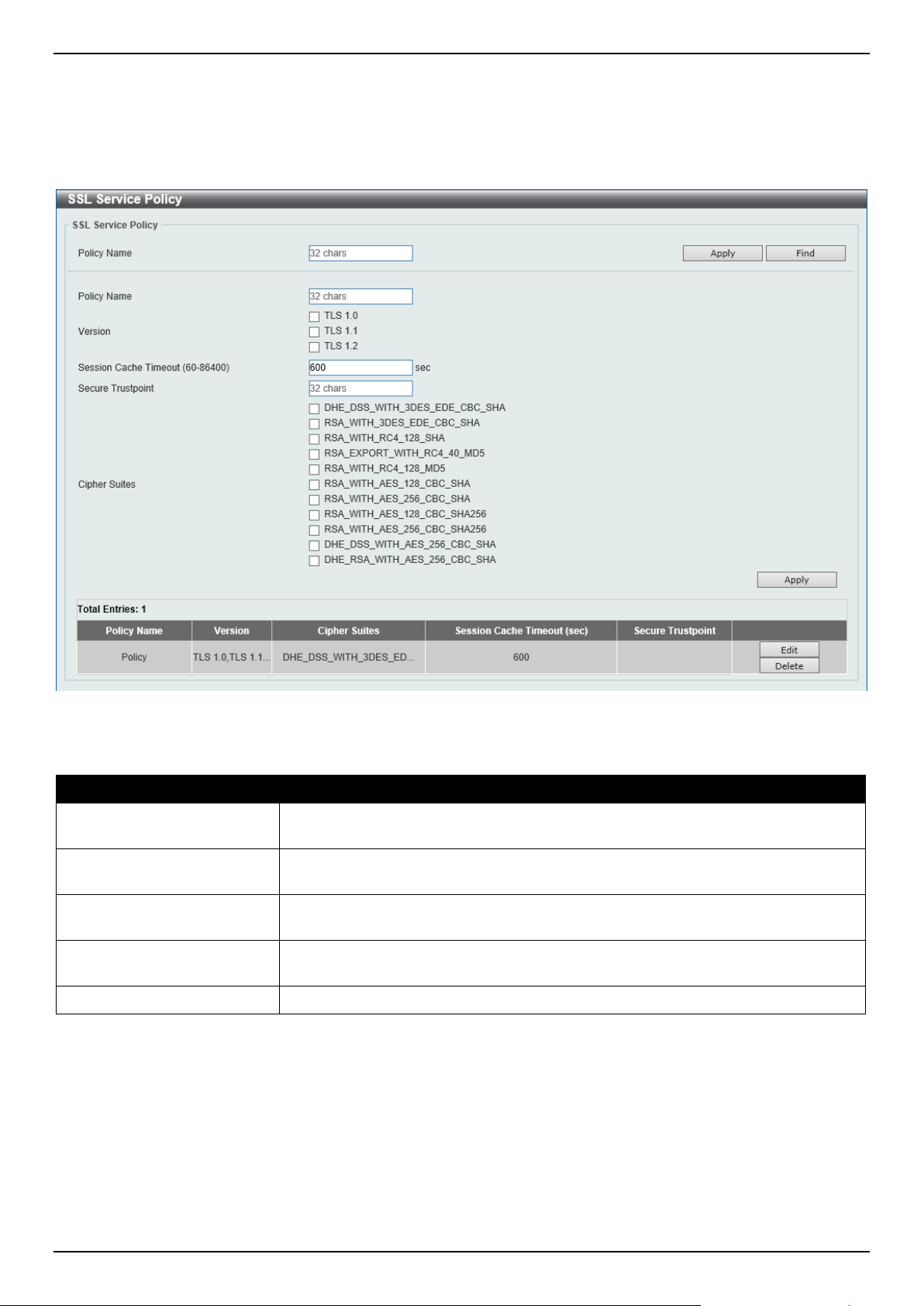
DGS-1520 Series Gigabit Ethernet Smart Managed Switch Web UI Reference Guide
487
SSL Service Policy
This window is used to display and configure the SSL service policy settings.
To view the following window, click Security > SSL > SSL Service Policy, as shown below:
Figure 9-102 SSL Service Policy Window
The fields that can be configured are described below:
Parameter Description
Policy Name
Enter the SSL service policy name here. This name can be up to 32 characters
long.
Version
Select the Transport Layer Security (TLS) version here. Options to choose from
are TLS 1.0, TLS 1.1, and TLS 1.2.
Session Cache Timeout
Enter the session cache timeout value used here. This value must be between 60
and 86400 seconds. By default, this value is 600 seconds.
Secure Trustpoint
Enter the secure trust point name here. This name can be up to 32 characters
long.
Cipher Suites
Select the cipher suites that will be associated with this profile here.
Click the Apply button to accept the changes made.
Click the Find button to locate a specific entry based on the information entered.
Click the Edit button to re-configure the specific entry.
Click the Delete button to remove the specified entry.
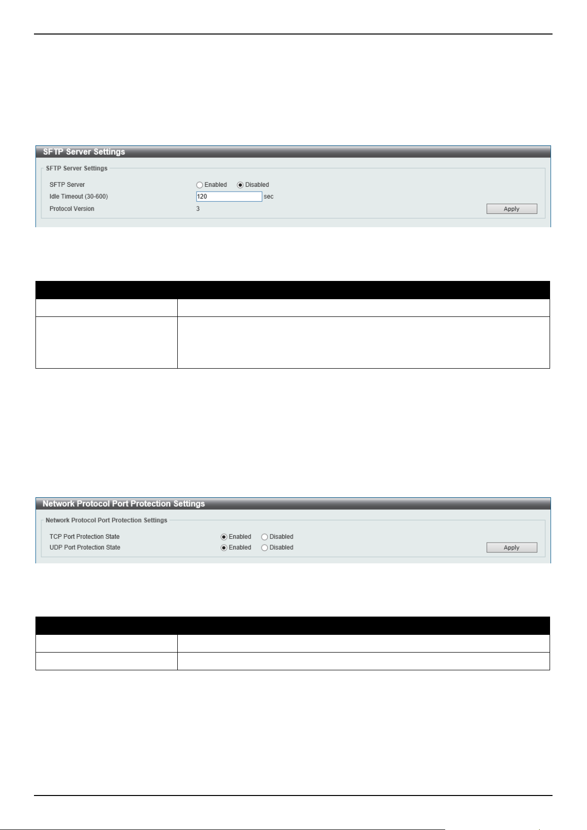
DGS-1520 Series Gigabit Ethernet Smart Managed Switch Web UI Reference Guide
488
SFTP Server Settings
This window is used to display and configure the Secure File Transfer Protocol (SFTP) server settings. SFTP is a
remotely secure file transfer protocol over a reliable data stream. Because SFTP itself does not provide authentication
and security, the SFTP server runs as a sub-system of the SSH server.
To view the following window, click Security > SFTP Server Settings, as shown below:
Figure 9-103 SFTP Server Settings Window
The fields that can be configured are described below:
Parameter Description
SFTP Server
Select to globally enable or disable the SFTP server feature here.
Idle Timeout
Enter the idle timeout value here. If the SFTP server detects no operation after the
duration of the idle timer for a specific SFTP session, the Switch will close this
SFTP session. The range is from 30 to 600 seconds. By default, this value is 120
seconds.
Click the Apply button to accept the changes made.
Network Protocol Port Protect Settings
This window is used to display and configure the network protocol port protection settings.
To view the following window, click Security > Network Protocol Port Protect Settings, as shown below:
Figure 9-104 Network Protocol Port Protect Settings Window
The fields that can be configured are described below:
Parameter Description
TCP Port Protect State
Select to enable or disable the TCP port network protocol protection function here.
UDP Port Protect State
Select to enable or disable the UDP port network protocol protection function here.
Click the Apply button to accept the changes made.
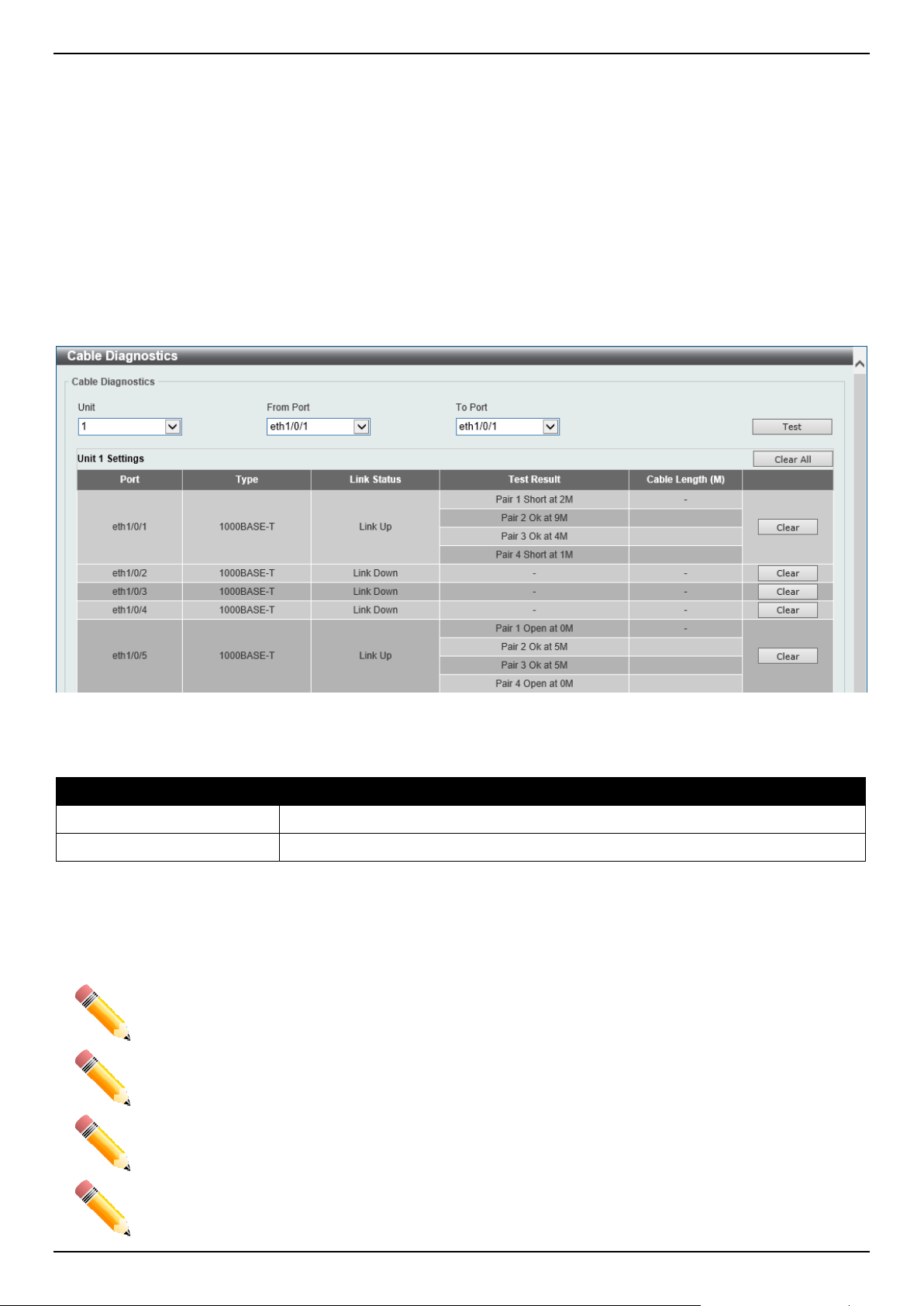
DGS-1520 Series Gigabit Ethernet Smart Managed Switch Web UI Reference Guide
489
10. OAM
Cable Diagnostics
DDM
Cable Diagnostics
The cable diagnostics feature is designed primarily for administrators or customer service representatives to verify and
test copper cables; it can rapidly determine the quality of the cables and the types of error.
To view the following window, click OAM > Cable Diagnostics, as shown below:
Figure 10-1 Cable Diagnostics Window
The fields that can be configured are described below:
Parameter Description
Unit
Select the Switch unit that will be used for this configuration here.
From Port - To Port
Select the appropriate port range used for the configuration here.
Click the Test button to test the specific port.
Click the Clear button to clear all the information for the specific port.
Click the Clear All button to clear all the information in this table.
NOTE: Cable diagnostic function limitations. Cable length detection is only supported on GE ports.
NOTE: The maximum cable diagnosis length is 120 meters.
NOTE: The deviation of cable length detection is about 5 meters for GE ports.
NOTE: For more accurate test results, use the TIA/EIA-568B pin assignment on the RJ45
connectors.
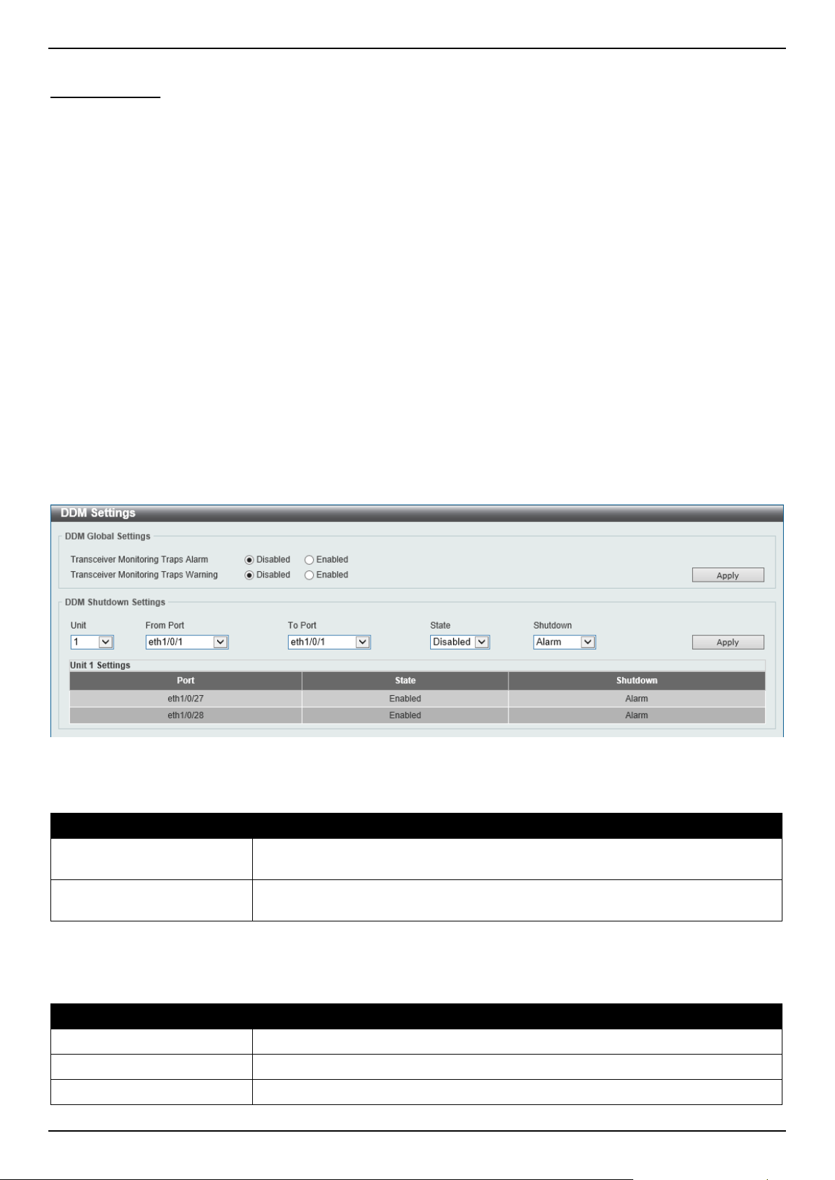
DGS-1520 Series Gigabit Ethernet Smart Managed Switch Web UI Reference Guide
490
Fault messages:
• Open - This pair is left open.
• Short - Two lines of this pair is shorted.
• CrossTalk - Lines of this pair is short with lines in other pairs.
• Unknown - The diagnosis does not obtain the cable status, please try again.
• NA - No cable was found, maybe it's because cable is out of diagnosis specification or the quality is too bad.
DDM
This folder contains windows that perform Digital Diagnostic Monitoring (DDM) functions on the Switch. There are
windows that allow the user to view the digital diagnostic monitoring status of SFP/SFP+ modules inserting to the
Switch and to configure alarm settings, warning settings, temperature threshold settings, voltage threshold settings,
bias current threshold settings, Tx power threshold settings, and Rx power threshold settings.
DDM Settings
The window is used to view and configure the action that will occur for specific ports when an exceeding alarm
threshold or warning threshold event is encountered.
To view the following window, click OAM > DDM > DDM Settings, as shown below:
Figure 10-2 DDM Settings Window
The fields that can be configured in DDM Global Settings are described below:
Parameter Description
Transceiver Monitoring
Traps Alarm
Select to enable or disable the transceiver monitoring traps alarm feature here.
Transceiver Monitoring
Traps Warning
Select to enable or disable the transceiver monitoring traps warning feature here.
Click the Apply button to accept the changes made.
The fields that can be configured in DDM Shutdown Settings are described below:
Parameter Description
Unit
Select the Switch unit that will be used for this configuration here.
From Port - To Port
Select the appropriate port range used for the configuration here.
State
Use the drop-down menu to enable or disable the DDM state.
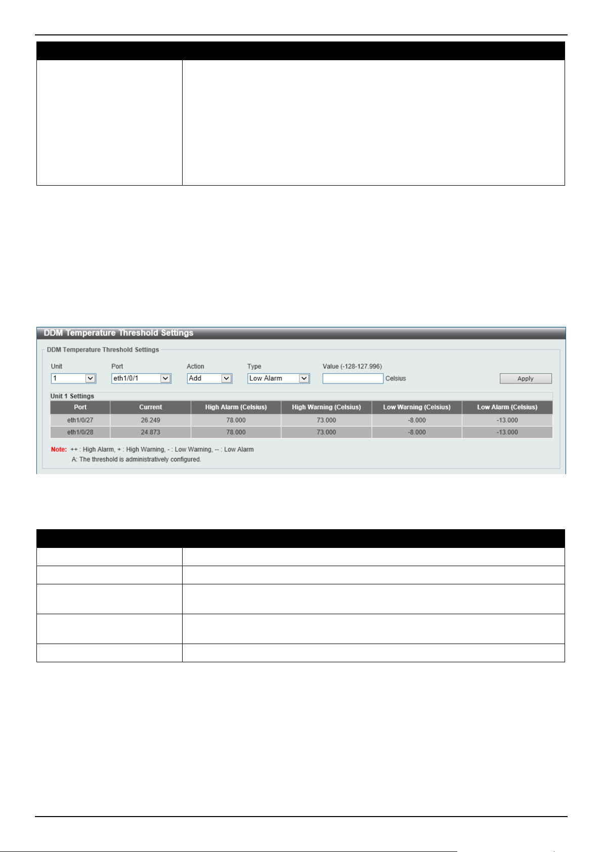
DGS-1520 Series Gigabit Ethernet Smart Managed Switch Web UI Reference Guide
491
Parameter Description
Shutdown
Specify whether to shut down the port, when the operating parameter exceeds the
alarm or warning threshold. Options to choose from are:
• Alarm - Shutdown the port when the configured alarm threshold range is
exceeded.
• Warning - Shutdown the port when the configured warning threshold range
is exceeded.
• None - The port will never shutdown regardless if the threshold ranges are
exceeded or not.
By default, the None option is used.
Click the Apply button to accept the changes made.
DDM Temperature Threshold Settings
This window is used to display and configure the DDM Temperature Threshold Settings for specific ports on the
Switch.
To view the following window, click OAM > DDM > DDM Temperature Threshold Settings, as shown below:
Figure 10-3 DDM Temperature Threshold Settings Window
The fields that can be configured are described below:
Parameter Description
Unit
Select the Switch unit that will be used for this configuration here.
Port
Select the port used for the configuration here.
Action Select the action that will be taken here. Options to choose from are Add and
Delete.
Type Select the type of temperature threshold. Options to choose from are Low Alarm,
Low Warning, High Alarm, and High Warning.
Value
Enter the threshold value. This value must be between -128 and 127.996 °C.
Click the Apply button to accept the changes made.
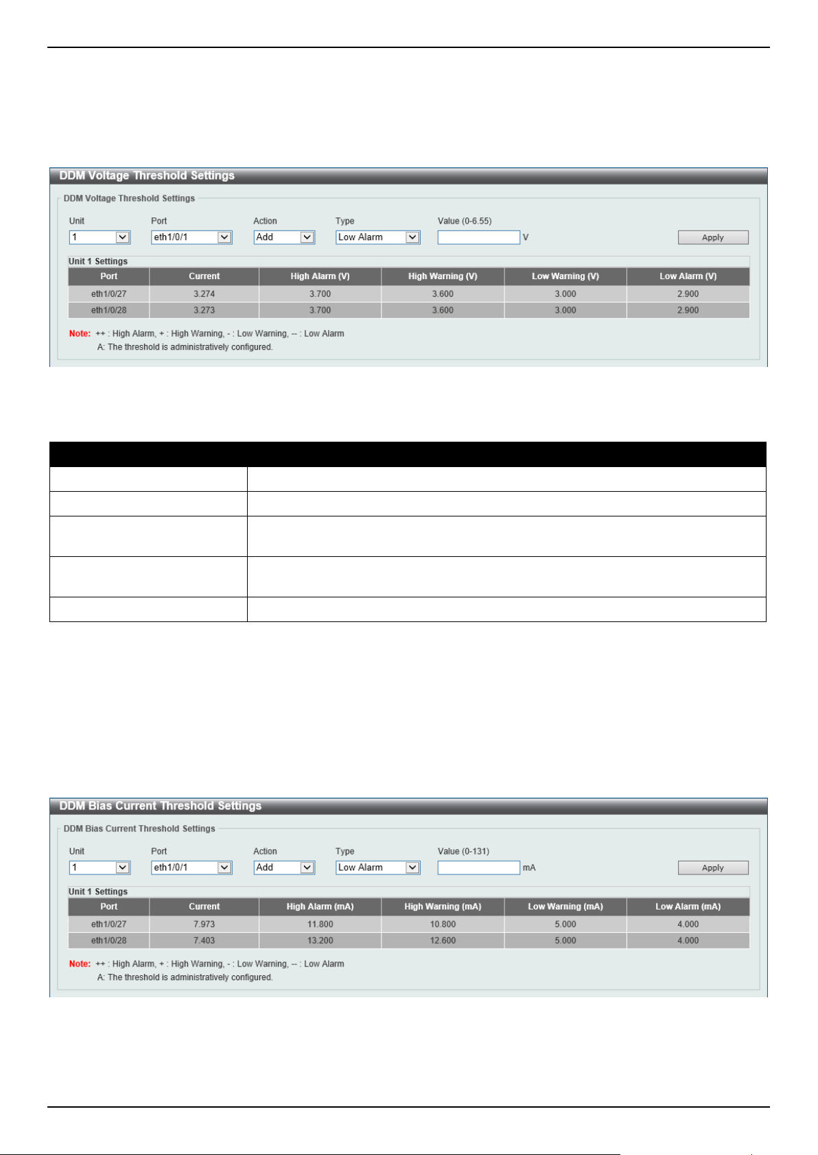
DGS-1520 Series Gigabit Ethernet Smart Managed Switch Web UI Reference Guide
492
DDM Voltage Threshold Settings
This window is used to display and configure the DDM Voltage Threshold Settings for specific ports on the Switch.
To view the following window, click OAM > DDM > DDM Voltage Threshold Settings, as shown below:
Figure 10-4 DDM Voltage Threshold Settings Window
The fields that can be configured are described below:
Parameter Description
Unit
Select the Switch unit that will be used for this configuration here.
Port
Select the port used for the configuration here.
Action Select the action that will be taken here. Options to choose from are Add and
Delete.
Type Select the type of voltage threshold. Options to choose from are Low Alarm, Low
Warning, High Alarm, and High Warning.
Value
Enter the threshold value. This value must be between 0 and 6.55 Volt.
Click the Apply button to accept the changes made.
DDM Bias Current Threshold Settings
This window is used to display and configure the threshold of the bias current for specific ports on the Switch.
To view the following window, click OAM > DDM > DDM Bias Current Threshold Settings, as shown below:
Figure 10-5 DDM Bias Current Threshold Settings Window
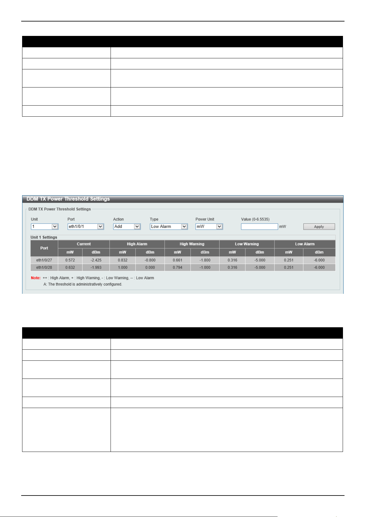
DGS-1520 Series Gigabit Ethernet Smart Managed Switch Web UI Reference Guide
493
The fields that can be configured are described below:
Parameter Description
Unit
Select the Switch unit that will be used for this configuration here.
Port
Select the port used for the configuration here.
Action Select the action that will be taken here. Options to choose from are Add and
Delete.
Type Select the type of bias current threshold. Options to choose from are Low Alarm,
Low Warning, High Alarm, and High Warning.
Value
Enter the threshold value. This value must be between 0 and 131 mA.
Click the Apply button to accept the changes made.
DDM TX Power Threshold Settings
This window is used to display and configure the threshold of TX power for specific ports on the Switch.
To view the following window, click OAM > DDM > DDM TX Power Threshold Settings, as shown below:
Figure 10-6 DDM TX Power Threshold Settings Window
The fields that can be configured are described below:
Parameter Description
Unit
Select the Switch unit that will be used for this configuration here.
Port
Select the port used for the configuration here.
Action Select the action that will be taken here. Options to choose from are Add and
Delete.
Type Select the type of TX power threshold. Options to choose from are Low Alarm,
Low Warning, High Alarm, and High Warning.
Power Unit Select the power unit here. Options to choose from are mW and dBm.
Value Enter the threshold value either in mW or dBm here.
• When selecting mW in the Power Unit drop-down list, this value must be
between 0 and 6.5535.
• When selecting dBm in the Power Unit drop-down list, this value must be
between -40 and 8.1647.
Click the Apply button to accept the changes made.
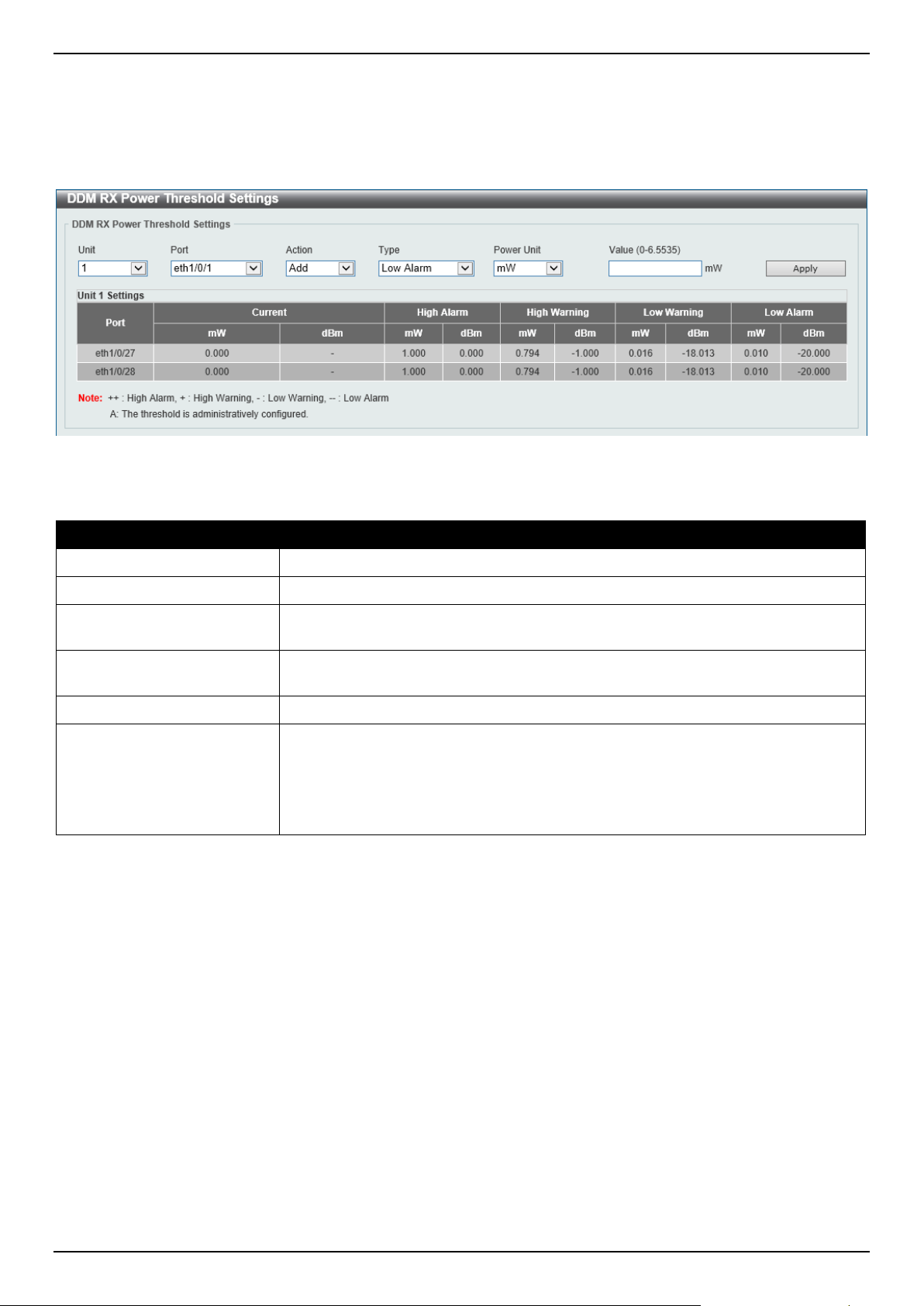
DGS-1520 Series Gigabit Ethernet Smart Managed Switch Web UI Reference Guide
494
DDM RX Power Threshold Settings
This window is used to display and configure the threshold of RX power for specific ports on the Switch.
To view the following window, click OAM > DDM > DDM RX Power Threshold Settings, as shown below:
Figure 10-7 DDM RX Power Threshold Settings Window
The fields that can be configured are described below:
Parameter Description
Unit
Select the Switch unit that will be used for this configuration here.
Port
Select the port used for the configuration here.
Action Select the action that will be taken here. Options to choose from are Add and
Delete.
Type Select the type of RX power threshold. Options to choose from are Low Alarm,
Low Warning, High Alarm, and High Warning.
Power Unit Select the power unit here. Options to choose from are mW and dBm.
Value Enter the threshold value either in mW or dBm here.
• When selecting mW in the Power Unit drop-down list, this value must be
between 0 and 6.5535.
• When selecting dBm in the Power Unit drop-down list, this value must be
between -40 and 8.1647.
Click the Apply button to accept the changes made.
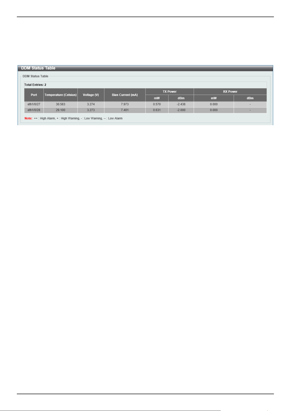
DGS-1520 Series Gigabit Ethernet Smart Managed Switch Web UI Reference Guide
495
DDM Status Table
This window is used to display the current operating digital diagnostic monitoring parameters and their values on the
SFP module for specified ports.
To view the following window, click OAM > DDM > DDM Status Table, as shown below:
Figure 10-8 DDM Status Table Window
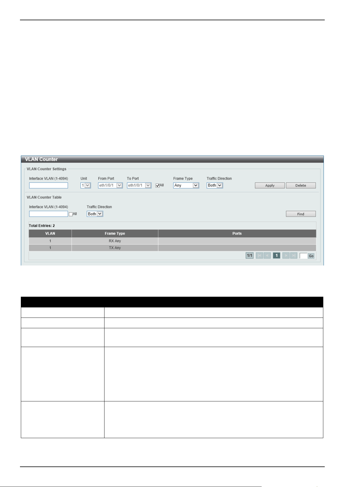
DGS-1520 Series Gigabit Ethernet Smart Managed Switch Web UI Reference Guide
496
11. Monitoring
VLAN Counter
Utilization
Statistics
Mirror Settings
sFlow
Device Environment
VLAN Counter
This window is used to display and configure the VLAN counter settings. This is used to create a control entry for
traffic statistics on specified Layer 2 VLAN interface(s).
To view the following window, click Monitoring > VLAN Counter, as shown below:
Figure 11-1 VLAN Counter Window
The fields that can be configured for VLAN Counter Settings are described below:
Parameter Description
Interface VLAN
Enter the VLAN ID that will be used here. The range is from 1 to 4094.
Unit
Select the Switch unit that will be used for this configuration here.
From Port - To Port
Select the range of ports that will be used for this configuration here.
Select the All option to use all the ports in this configuration.
Frame Type
Select the frame type here. Options to choose from are:
• Broadcast - Specifies to count only broadcast frames.
• Multicast - Specifies to count only multicast frames.
• Unicast - Specifies to count only unicast frames.
• Any - Specifies to count all frames regardless of the frame type.
• All - Specifies to count the four frame types mentioned above.
Traffic Direction
Select the traffic direction here. Options to choose from are:
• RX - Specifies to count ingress traffic.
• TX - Specifies to count egress traffic.
• Both - Specifies to count ingress and egress traffic.
Click the Apply button to accept the changes made.
Click the Delete button to delete the specified entry (or entries) based on the information entered/selected.
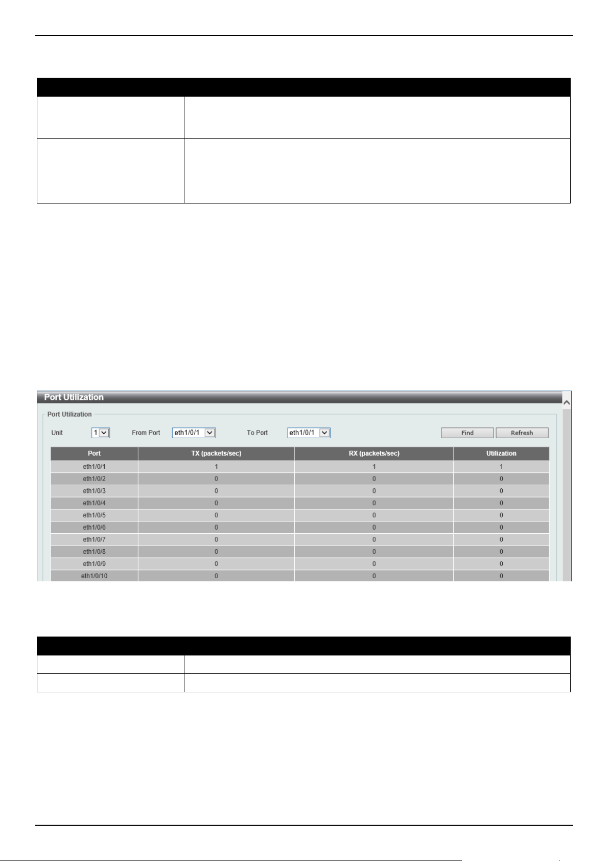
DGS-1520 Series Gigabit Ethernet Smart Managed Switch Web UI Reference Guide
497
The fields that can be configured for VLAN Counter Table are described below:
Parameter Description
Interface VLAN
Enter the VLAN ID that will be used in the display here. The range is from 1 to
4094. Select the All option to display counter information associated with all VLAN
interfaces.
Traffic Direction
Select the traffic direction to display here. Options to choose from are:
• RX - Specifies to display ingress traffic count settings.
• TX - Specifies to display egress traffic count settings.
• Both - Specifies to display ingress and egress traffic count settings.
Click the Find button to display entries in the table based on the information entered/selected.
Enter a page number and click the Go button to navigate to a specific page when multiple pages exist.
Utilization
Port Utilization
This window is used to view the port utilization table.
To view the following window, click Monitoring > Utilization > Port Utilization, as shown below:
Figure 11-2 Port Utilization Window
The fields that can be configured are described below:
Parameter Description
Unit
Select the Switch unit that will be used here.
From Port - To Port
Select the range of ports that will be used here.
Click the Find button to display entries in the table based on the information entered/selected.
Click the Refresh button to refresh the information displayed in the table.
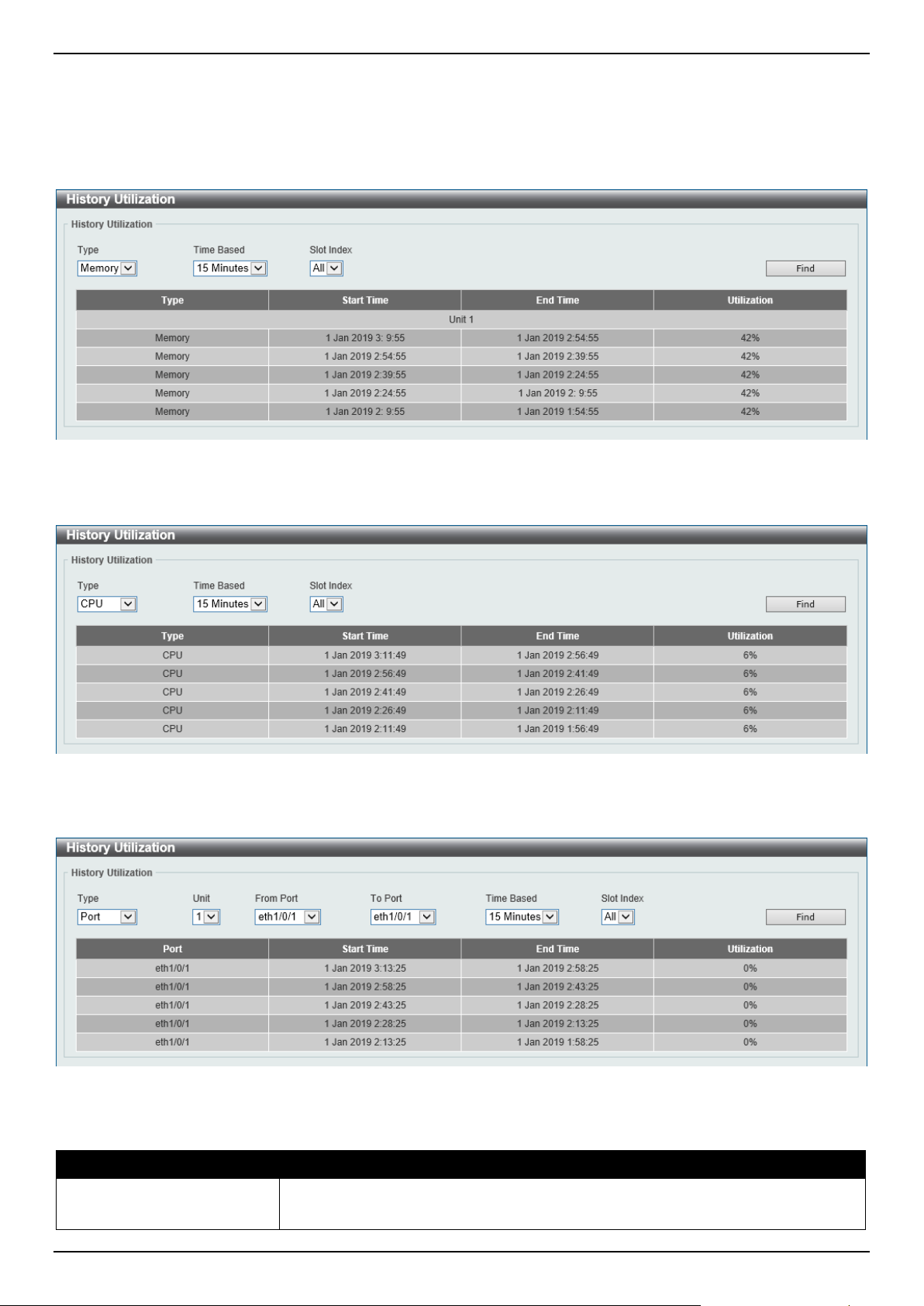
DGS-1520 Series Gigabit Ethernet Smart Managed Switch Web UI Reference Guide
498
History Utilization
This window is used to view the memory, CPU and port history utilization.
To view the following window, click Monitoring > Utilization > History Utilization, as shown below:
Figure 11-3 History Utilization (Memory) Window
After selecting CPU as the Type, the following window will appear:
Figure 11-4 History Utilization (CPU) Window
After selecting Port as the Type, the following window will appear:
Figure 11-5 History Utilization (Port) Window
The fields that can be configured are described below:
Parameter Description
Type
Select the history utilization type to display here. Options to choose from are:
• Memory - Specifies to display the historical memory utilization information.
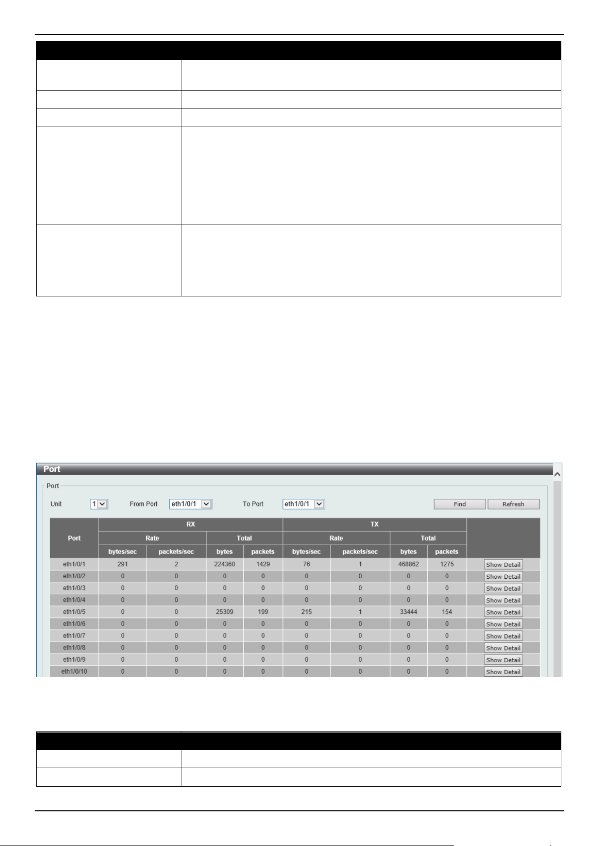
DGS-1520 Series Gigabit Ethernet Smart Managed Switch Web UI Reference Guide
499
Parameter Description
• CPU - Specifies to display the historical CPU utilization information.
• Port - Specifies to display the historical port utilization information.
Unit
Select the Switch unit that will be used here.
From Port - To Port
Select the range of ports that will be used here.
Time Based
Select the time-based statistical count value here. Options to choose from are:
• 15 Minutes - Specifies to display slots of 15-minute based information.
• 1 Day - Specifies to display slots of daily-based information.
For 15-minute based statistics, slot 1 represents the time from 15 minutes ago until
now, slot 2 represents the time from 30 minutes ago until 15 minutes ago and so
on. For 1-day based statistics, slot 1 represents the time from 24 hours ago until
now and slot 2 represents the time from 48 hours ago until 24 hours ago.
Slot Index
Select the slot index here.
• After selecting to use 15-minute slots, the options to choose from are All,
and 1 to 5.
• After selecting to use 1-day slots, the options to choose from are All, and 1
to 2.
Click the Find button to display entries in the table based on the information selected.
Statistics
Port
This window is used to view the port statistics information.
To view the following window, click Monitoring > Statistics > Port, as shown below:
Figure 11-6 Port Window
The fields that can be configured are described below:
Parameter Description
Unit
Select the Switch unit that will be used in this display here.
From Port - To Port
Select the range of ports that will be used in this display here.
Click the Find button to display entries in the table based on the information selected.
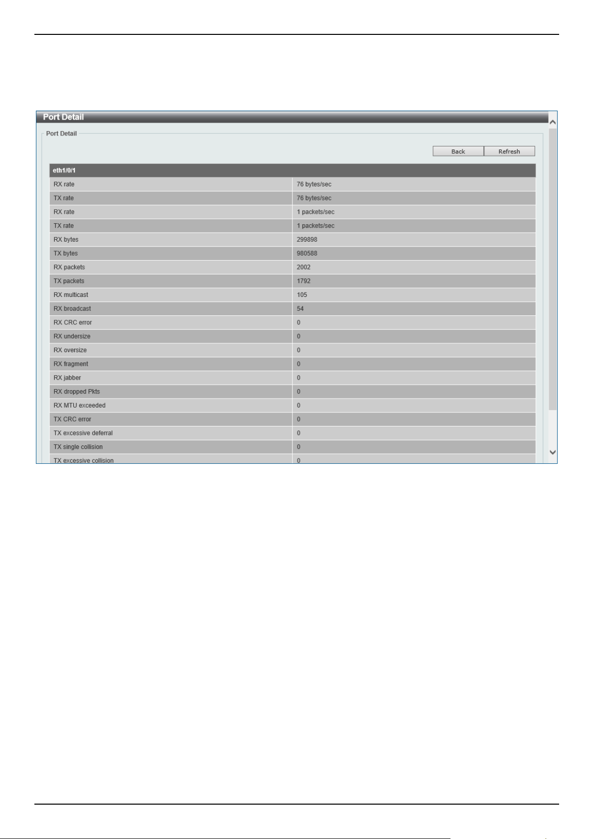
DGS-1520 Series Gigabit Ethernet Smart Managed Switch Web UI Reference Guide
500
Click the Refresh button to refresh the information displayed in the table.
Click the Show Detail button to view detailed statistics information on the specified port.
After clicking the Show Detail button, the following window will appear:
Figure 11-7 Port (Show Detail) Window
Click the Back button to return to the previous window.
Click the Refresh button to refresh the information displayed in the table.
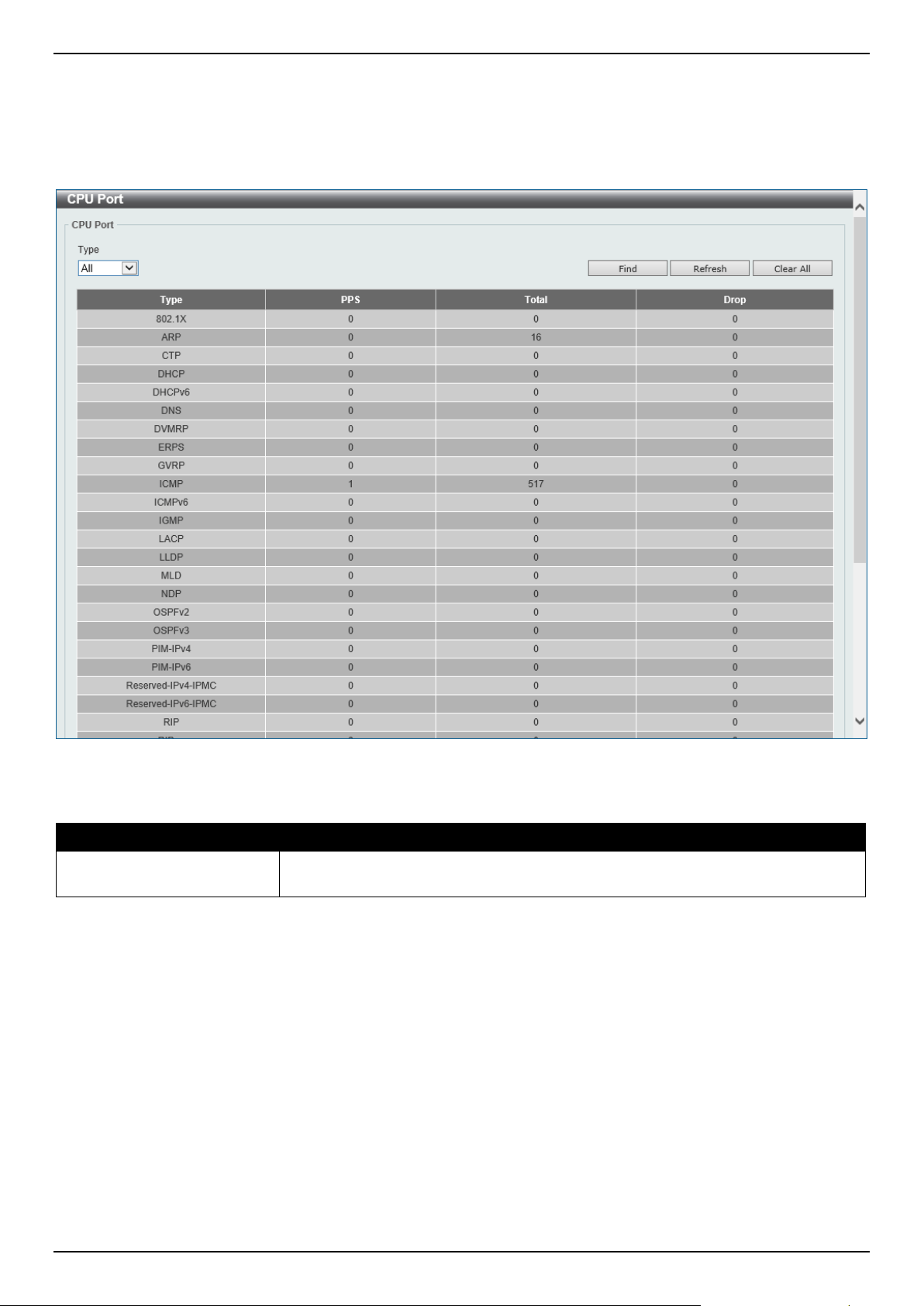
DGS-1520 Series Gigabit Ethernet Smart Managed Switch Web UI Reference Guide
501
CPU Port
This window is used to view the CPU statistics information.
To view the following window, click Monitoring > Statistics > CPU Port, as shown below:
Figure 11-8 CPU Port Window
The fields that can be configured are described below:
Parameter Description
Type Select the type of information to display here. Options to choose from are All,
Layer 2 (L2), Layer 3 (L3), and Protocol.
Click the Find button to display entries in the table based on the information selected.
Click the Refresh button to refresh the information displayed in the table.
Click the Clear All button clear all the statistics information displayed in the table.
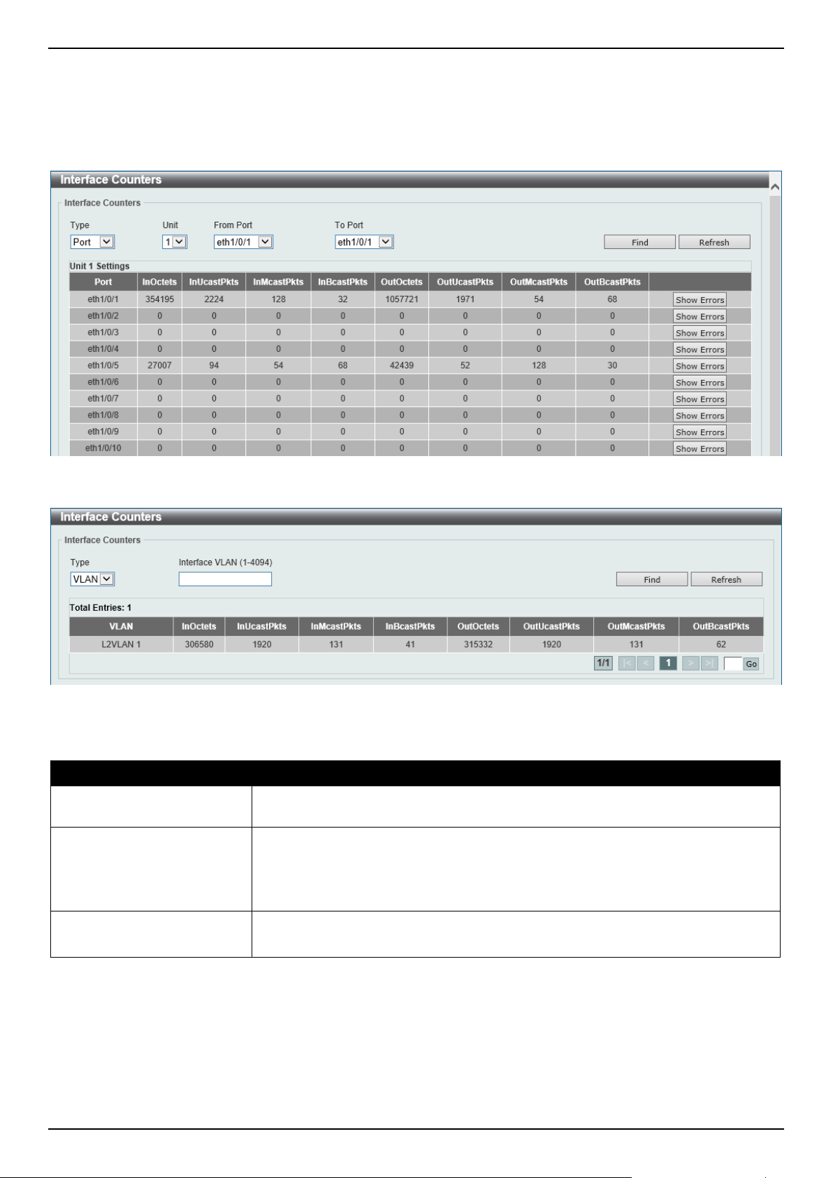
DGS-1520 Series Gigabit Ethernet Smart Managed Switch Web UI Reference Guide
502
Interface Counters
This window is used to view the interface counter information.
To view the following window, click Monitoring > Statistics > Interface Counters, as shown below:
Figure 11-9 Interface Counters (Port) Window
Figure 11-10 Interface Counters (VLAN) Window
The fields that can be configured are described below:
Parameter Description
Type Select the type of information to display here. Options to choose from are Port and
VLAN.
Port
Select this option to display interface counters per-port.
• Unit - Select the Switch unit that will be used in this display here.
• From Port / To Port - Select the range of ports that will be used in this
display here.
VLAN
Select this option to display interface counters per-VLAN.
• Interface VLAN - Enter the ID of the interface VLAN to display here.
Click the Find button to display entries in the table based on the information selected.
Click the Refresh button to refresh the information displayed in the table.
Click the Show Errors button to view detailed error information on the specified port.
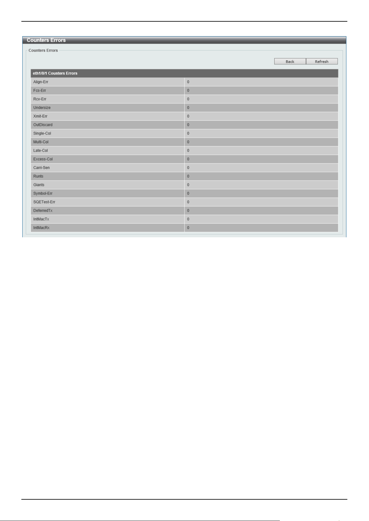
DGS-1520 Series Gigabit Ethernet Smart Managed Switch Web UI Reference Guide
503
After clicking the Show Errors button, the following window will appear:
Figure 11-11 Interface Counters (Show Errors) Window
Click the Back button to return to the previous window.
Click the Refresh button to refresh the information displayed in the table.
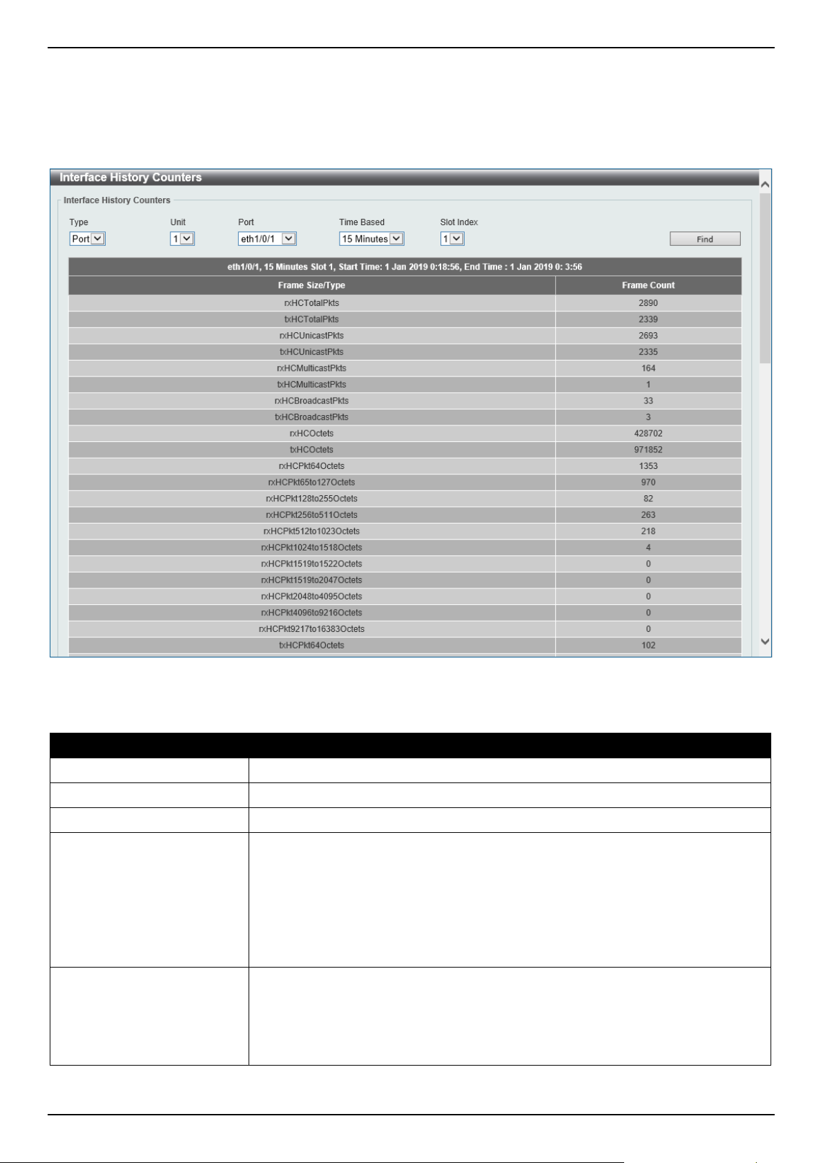
DGS-1520 Series Gigabit Ethernet Smart Managed Switch Web UI Reference Guide
504
Interface History Counters
This window is used to view the history counter information per interface.
To view the following window, click Monitoring > Statistics > Interface History Counters, as shown below:
Figure 11-12 Interface History Counters (Port) Window
The fields that can be configured are described below:
Parameter Description
Type
Select the type of information to display here.
Unit
Select the Switch unit that will be used in this display here.
Port
Select the port that will be used in this display here.
Time Based
Select the time-based statistical count value here. Options to choose from are:
• 15 Minutes - Specifies to display slots of 15-minute based information.
• 1 Day - Specifies to display slots of daily-based information.
For 15-minute based statistics, slot 1 represents the time from 15 minutes ago until
now, slot 2 represents the time from 30 minutes ago until 15 minutes ago and so
on. For 1-day based statistics, slot 1 represents the time from 24 hours ago until
now and slot 2 represents the time from 48 hours ago until 24 hours ago.
Slot index
Select the slot index here.
• After selecting to use 15-minute slots, the options to choose from are All,
and 1 to 5.
• After selecting to use 1-day slots, the options to choose from are All, and 1
to 2.
Click the Find button to display entries in the table based on the information selected/entered.
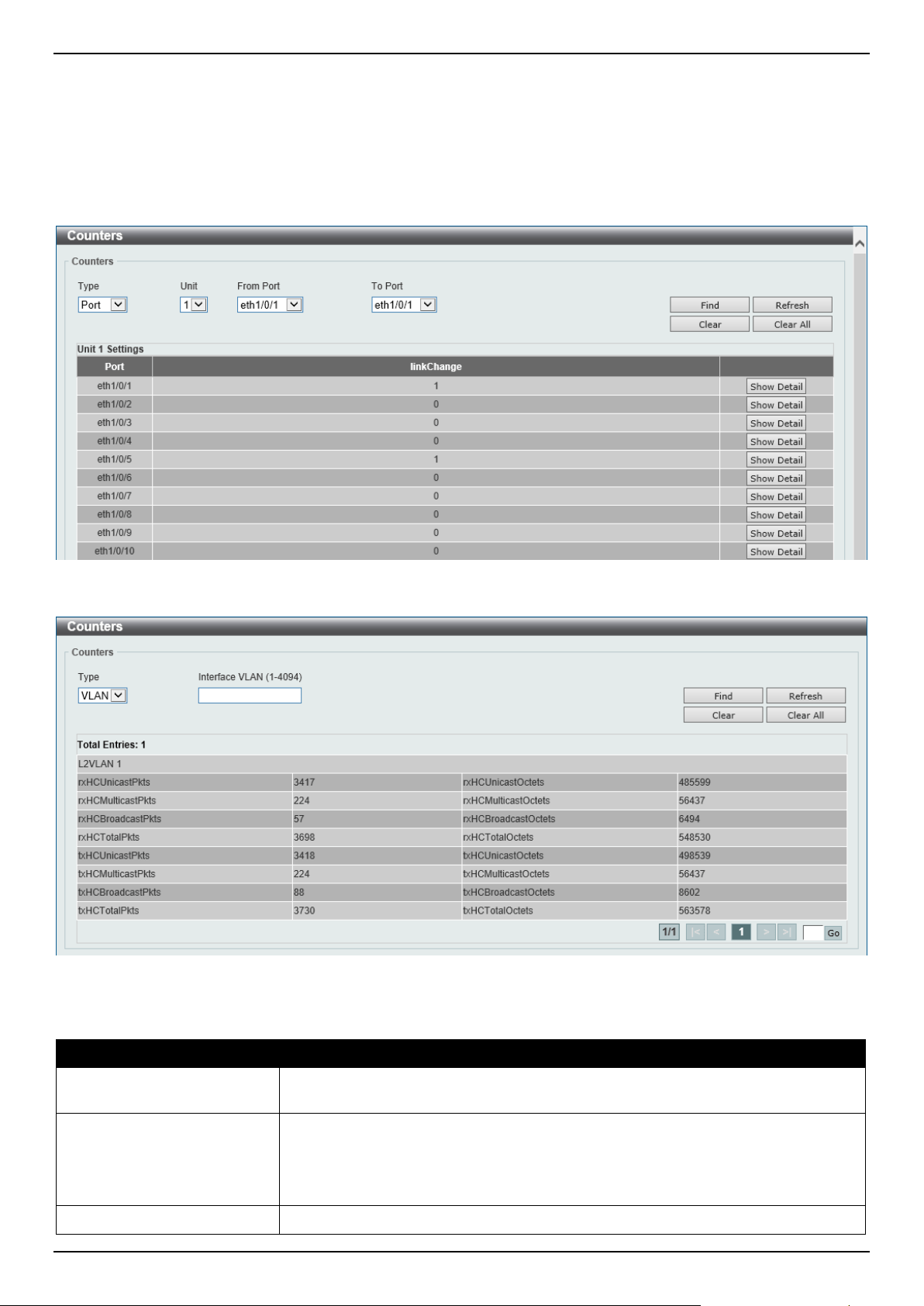
DGS-1520 Series Gigabit Ethernet Smart Managed Switch Web UI Reference Guide
505
Counters
This window is used to view and clear counter information.
To view the following window, click Monitoring > Statistics > Counters, as shown below:
Figure 11-13 Counters (Port) Window
Figure 11-14 Counters (VLAN) Window
The fields that can be configured are described below:
Parameter Description
Type Select the type of information to display here. Options to choose from are Port and
VLAN.
Port
Select this option to display counters per-port.
• Unit - Select the Switch unit that will be used in this display here.
• From Port / To Port - Select the range of ports that will be used in this
display here.
VLAN
Select this option to display counters per-VLAN.
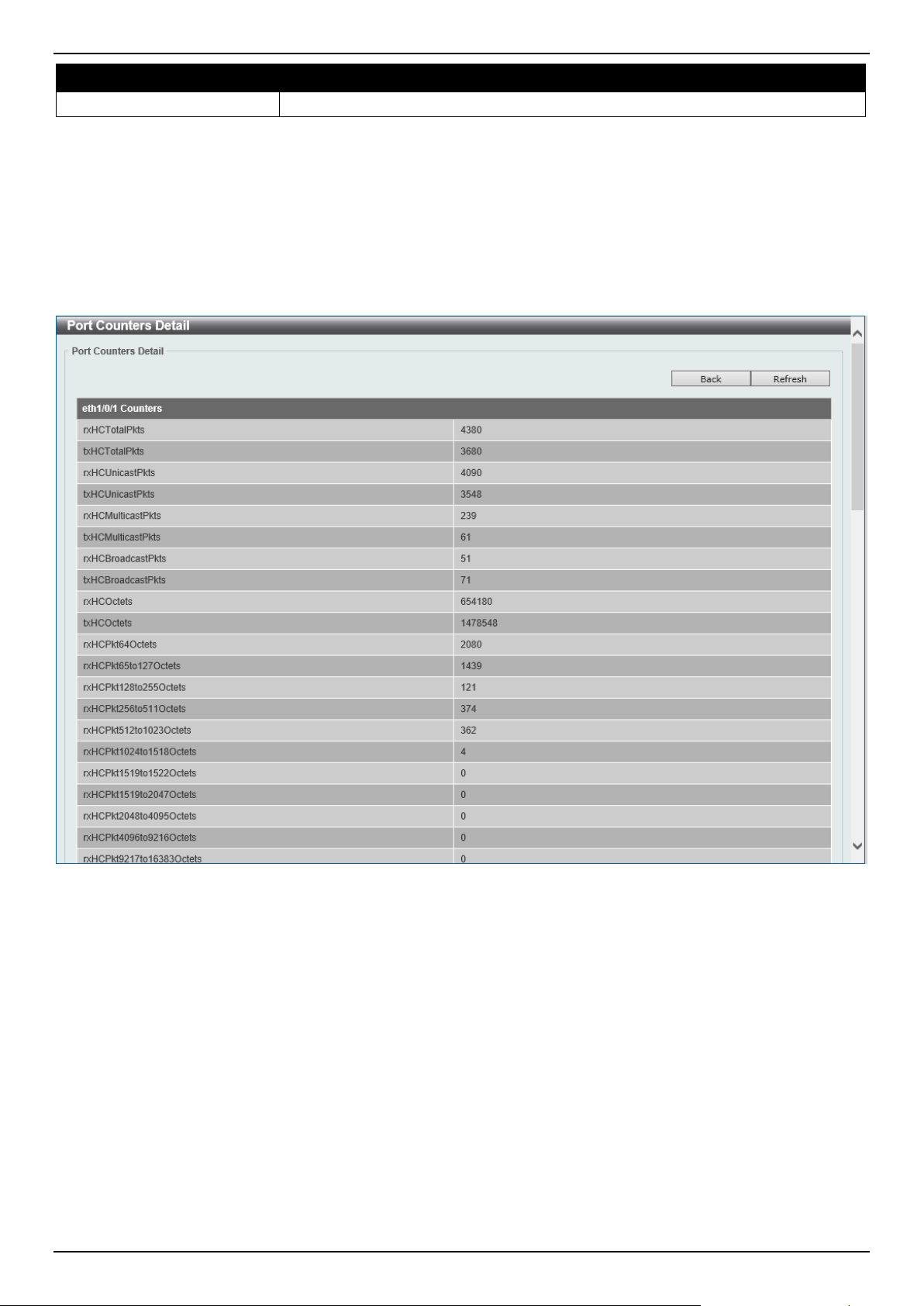
DGS-1520 Series Gigabit Ethernet Smart Managed Switch Web UI Reference Guide
506
Parameter Description
• Interface VLAN - Enter the ID of the interface VLAN to display here.
Click the Find button to display entries in the table based on the information selected.
Click the Refresh button to refresh the counter information displayed in the table.
Click the Clear button clear the counter information displayed in the table based on the information selected.
Click the Clear All button clear all the counter information displayed in the table.
Click the Show Detail button to view detailed counter information on the specified port.
After clicking the Show Detail button, the following window will appear:
Figure 11-15 Counters (Show Detail) Window
Click the Back button to return to the previous window.
Click the Refresh button to refresh the information displayed in the table.
Mirror Settings
This window is used to display and configure the mirror feature's settings. The Switch allows users to copy frames
transmitted and received on a port and redirect the copies to another port. Attach a monitoring device to the mirroring
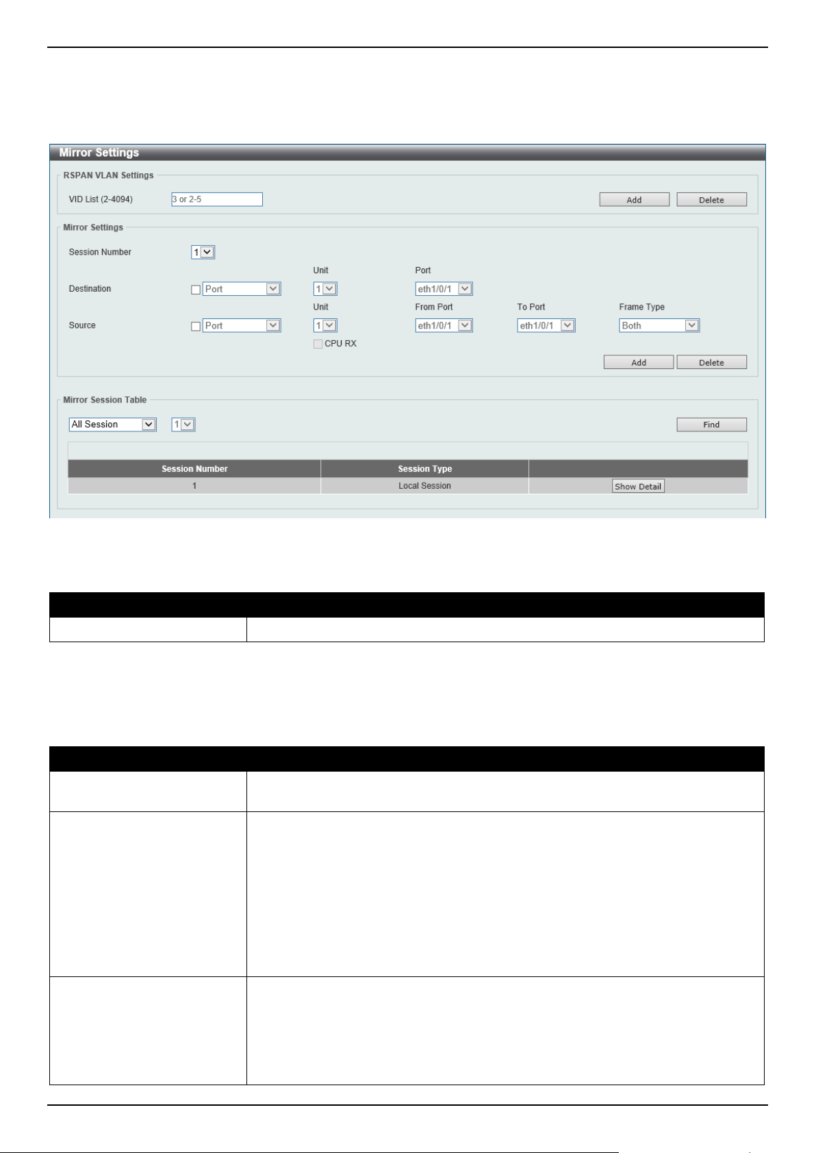
DGS-1520 Series Gigabit Ethernet Smart Managed Switch Web UI Reference Guide
507
port, such as a sniffer or an RMON probe, to view details about the packets passing through the first port. This is
useful for network monitoring and troubleshooting purposes.
To view the following window, click Monitoring > Mirror Settings, as shown below:
Figure 11-16 Mirror Settings Window
The fields that can be configured for RSPAN VLAN Settings are described below:
Parameter Description
VID List
Enter the VLAN list ID(s) that will be associated with this configuration here.
Click the Add button to add the VLAN(s) to the configuration.
Click the Delete button to delete the VLAN(s) from the configuration.
The fields that can be configured for Mirror Settings are described below:
Parameter Description
Session Number
Select the mirror session number for this entry here. This number is between 1 and
4.
Destination Tick the checkbox, next to the Destination option, to configure the destination for
this port mirror entry.
In the first drop-down menu, select the destination type option. Options to choose
from are:
• Port - After selecting this option, select the Switch Unit ID, and destination
Port number from the drop-down menus.
• Remote VLAN - After selecting this option, select the Switch Unit ID and
destination Port number from the drop-down menus and enter the VID in
the space provided. The VID must be between 2 and 4094.
Source Tick the checkbox, next to the Source option, to configure the source for this port
mirror entry.
In the first drop-down menu, select the source type option. Options to choose from
are:
• Port - After selecting this option, select the Switch Unit ID, From Port and
To Port numbers from the drop-down menus. Lastly select the Frame Type
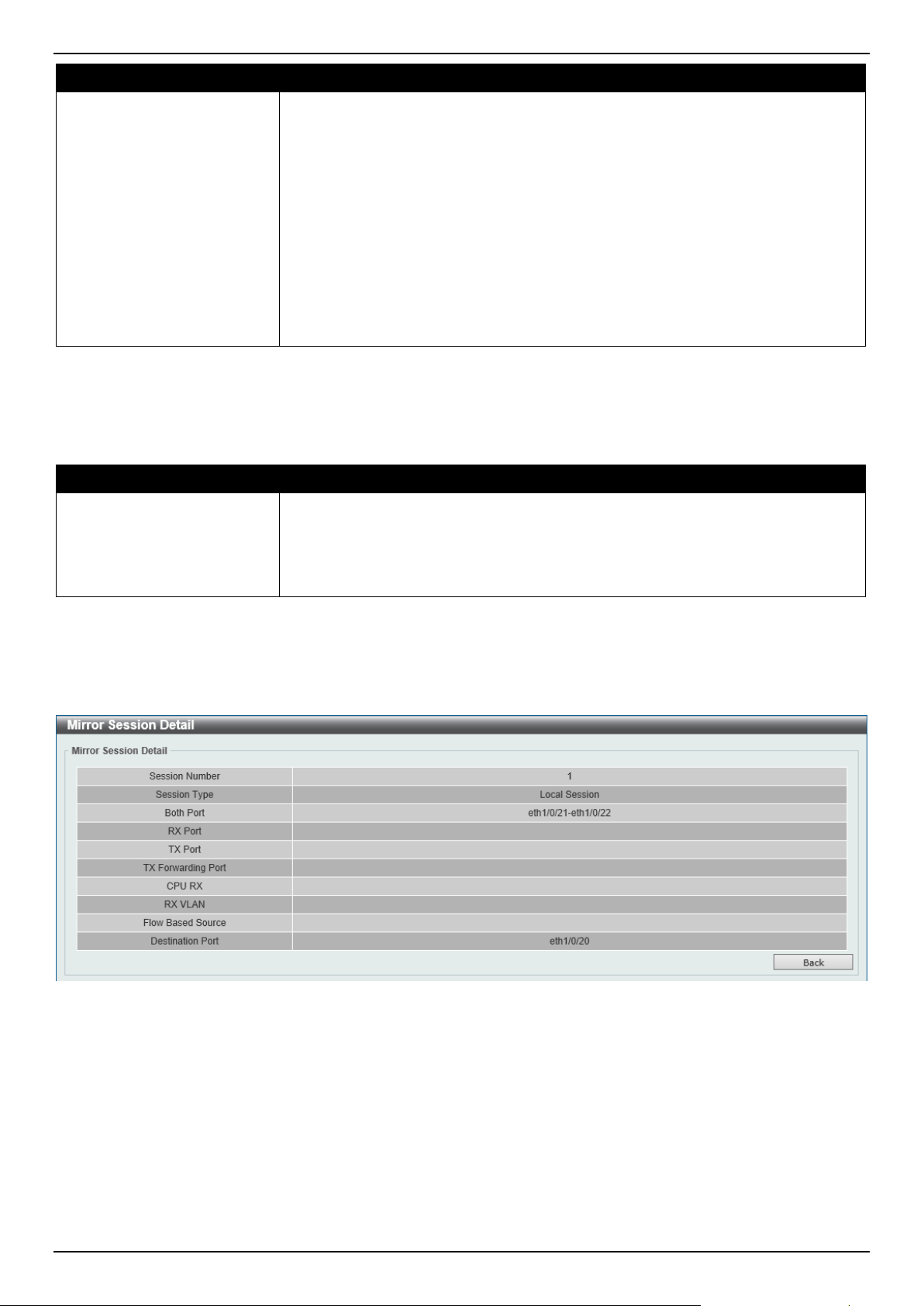
DGS-1520 Series Gigabit Ethernet Smart Managed Switch Web UI Reference Guide
508
Parameter Description
option from the last drop-down menu. Options to choose from are Both, RX,
TX, and TX Forwarding. When selecting Both, traffic in both the incoming
and outgoing directions will be mirrored. When selecting RX, traffic in only
the incoming direction will be mirrored. When selecting TX, traffic in only the
outgoing direction will be mirrored. Select the CPU RX option to also
monitor CPU RX traffic.
• ACL - After selecting this option, enter the ACL Name in the space
provided.
• VLAN - After selecting this option, enter the VID List in the space provided
and select the Frame Type from the drop-down menu. The only frame type
supported is RX.
• Remote VLAN - After selecting this option, enter the VID in the space
provided. The VID must be between 2 and 4094.
Click the Add button to add the newly configured mirror entry based on the information entered.
Click the Delete button to delete an existing mirror entry based on the information entered.
The fields that can be configured for Mirror Session Table are described below:
Parameter Description
Mirror Session Type
Select the mirror session type of information that will be displayed from the drop-
down menu. Options to choose from are All Session, Session Number, Remote
Session, and Local Session.
After selecting the Session Number option, select the session number from the
second drop-down menu. This number is from 1 to 4.
Click the Find button to locate a specific entry based on the information entered.
Click the Show Detail button to view detailed information about the mirror session.
After clicking the Show Detail button, the following window will appear:
Figure 11-17 Mirror Settings (Show Detail) Window
Click the Back button to return to the previous page.
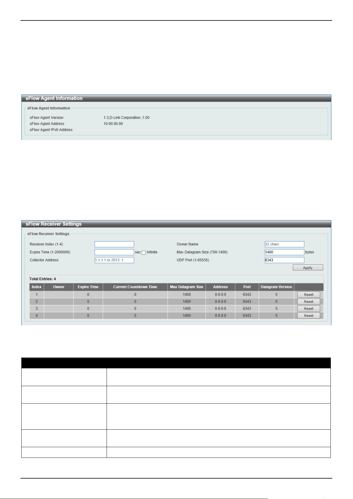
DGS-1520 Series Gigabit Ethernet Smart Managed Switch Web UI Reference Guide
509
sFlow
sFlow Agent Information
This window is used to view the sFlow agent information.
To view the following window, click Monitoring > sFlow > sFlow Agent Information, as shown below:
Figure 11-18 sFlow Agent Information Window
sFlow Receiver Settings
This window is used to display and configure receivers for the sFlow agents. Receivers cannot be added to or
removed from the sFlow agent.
To view the following window, click Monitoring > sFlow > sFlow Receiver Settings, as shown below:
Figure 11-19 sFlow Receiver Settings Window
The fields that can be configured are described below:
Parameter Description
Receiver Index
Enter the index number of the receiver here. This number must be between 1 and
4.
Owner Name
Enter the owner name of the receiver here. This name can be up to 32 characters
long.
Expire Time
Enter the expiration time for the entry here. The parameters of the entry will reset
when the timer expired. The range is from 1 to 2000000 seconds.
Selecting Infinite specifies that the entry will not expire.
Max Datagram Size
Enter the maximum number of data bytes of a single sFlow datagram here. The
range is from 700 to 1400 bytes. By default, this value is 1400 bytes.
Collector Address
Enter the remote sFlow collector's IPv4 or IPv6 address here.
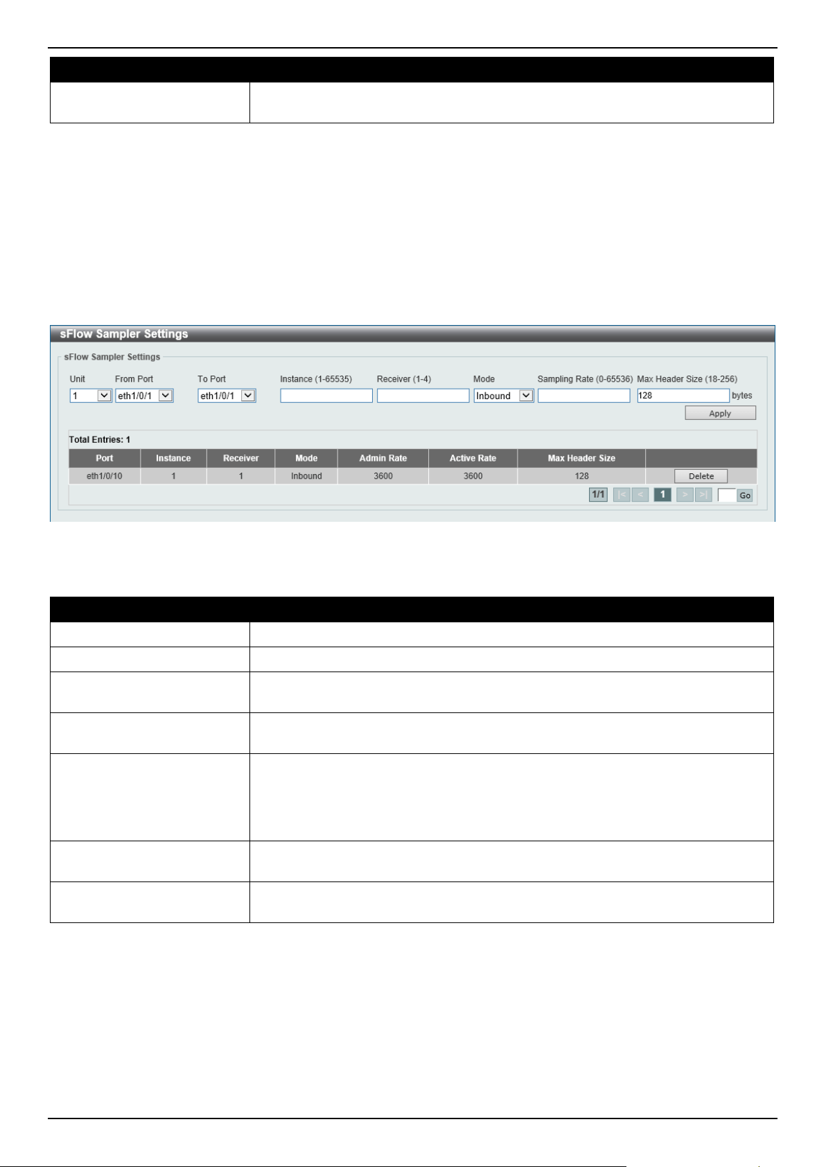
DGS-1520 Series Gigabit Ethernet Smart Managed Switch Web UI Reference Guide
510
Parameter Description
UDP Port
Enter the remote sFlow collector's UDP port number here. This number must be
between 1 and 65535. By default, this value is 6343.
Click the Apply button to accept the changes made.
Click the Reset button to reset the specified entry's settings to the default settings.
sFlow Sampler Settings
This window is used to display and configure the sFlow sampler settings.
To view the following window, click Monitoring > sFlow > sFlow Sampler Settings, as shown below:
Figure 11-20 sFlow Sampler Settings Window
The fields that can be configured are described below:
Parameter Description
Unit
Select the Switch unit that will be used for this configuration here.
From Port - To Port
Select the appropriate port range used for the configuration here.
Instance
Enter the instance index number if multiple samplers are associated with one
interface. The range is from 1 to 65535.
Receiver
Enter the receiver index for this sampler. If not specified, the value is 0. This value
must be between 1 and 4.
Mode
Select the mode here. Options to choose from are:
• Selecting Inbound specifies to sample ingress packets.
• Selecting Outbound specifies to sample egress packets.
By default, the Inbound option is used.
Sampling Rate
Enter the packet-sampling rate here. This value must be between 0 and 65536.
Entering 0 will disable this function. By default, this value is 0.
Max Header Size
Enter the maximum number of bytes that should be copied from sampled packets.
This value must be between 18 and 256 bytes. By default, this value is 128 bytes.
Click the Apply button to accept the changes made.
Click the Delete button to remove the specified entry.
Enter a page number and click the Go button to navigate to a specific page when multiple pages exist.
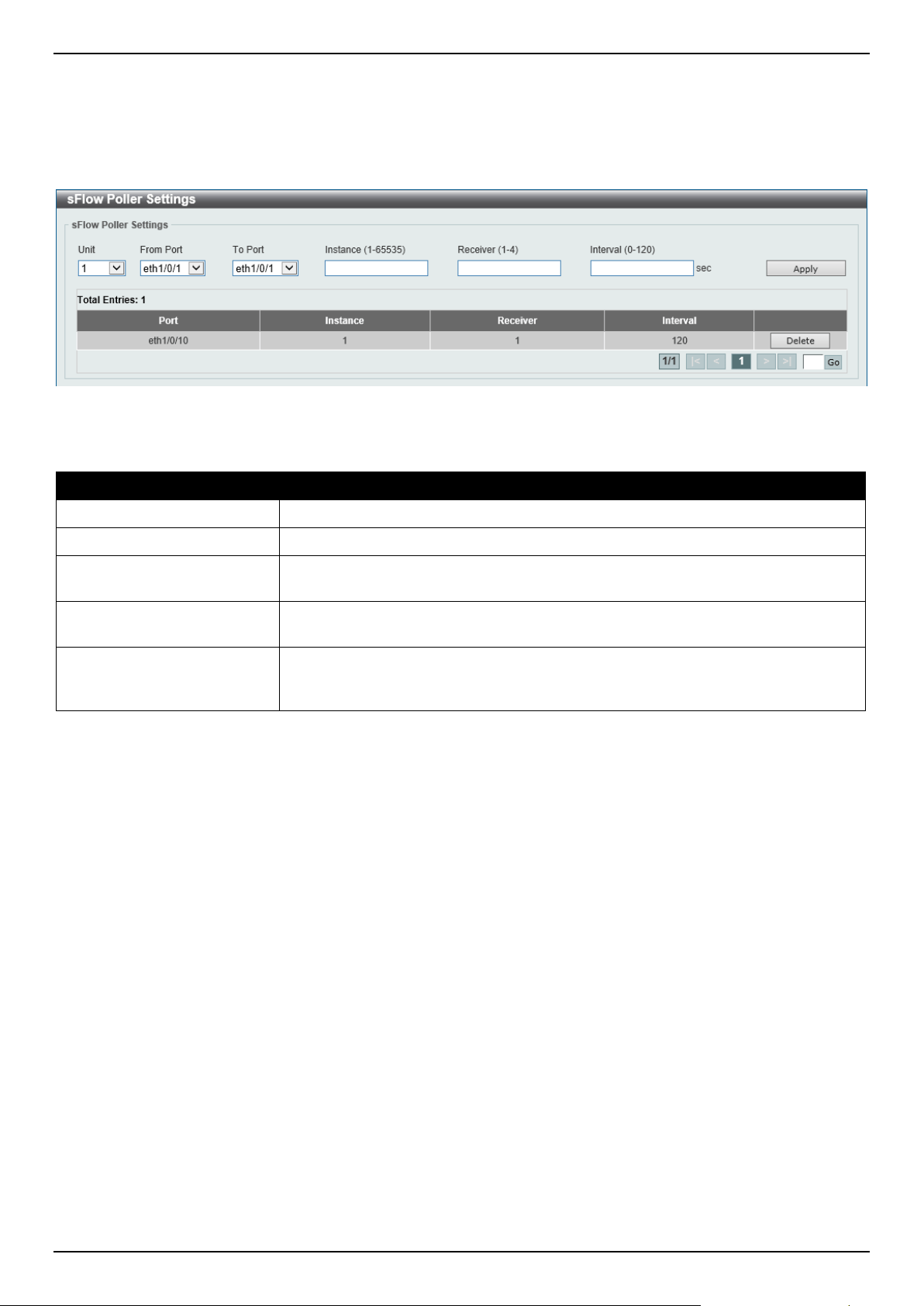
DGS-1520 Series Gigabit Ethernet Smart Managed Switch Web UI Reference Guide
511
sFlow Poller Settings
This window is used to display and configure the sFlow poller settings.
To view the following window, click Monitoring > sFlow > sFlow Poller Settings, as shown below:
Figure 11-21 sFlow Poller Settings Window
The fields that can be configured are described below:
Parameter Description
Unit
Select the Switch unit that will be used for this configuration here.
From Port - To Port
Select the appropriate port range used for the configuration here.
Instance
Enter the instance index number if multiple samplers are associated with one
interface. The range is from 1 to 65535.
Receiver
Enter the receiver index value for this poller here. This value must be between 1
and 4.
Interval
Enter the maximum number of seconds between successive polling samples. This
value must be between 0 and 120 seconds. Entering 0 will disable this feature. By
default, this value is 0.
Click the Apply button to accept the changes made.
Click the Delete button to remove the specified entry.
Enter a page number and click the Go button to navigate to a specific page when multiple pages exist.
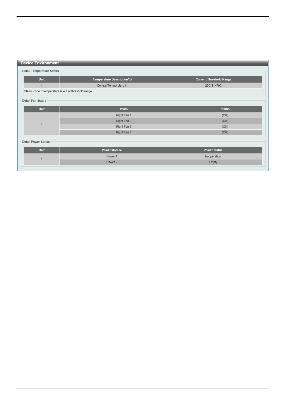
DGS-1520 Series Gigabit Ethernet Smart Managed Switch Web UI Reference Guide
512
Device Environment
The device environment feature displays the Switch internal temperature status.
To view the following window, click Monitoring > Device Environment, as shown below:
Figure 11-22 Device Environment Window
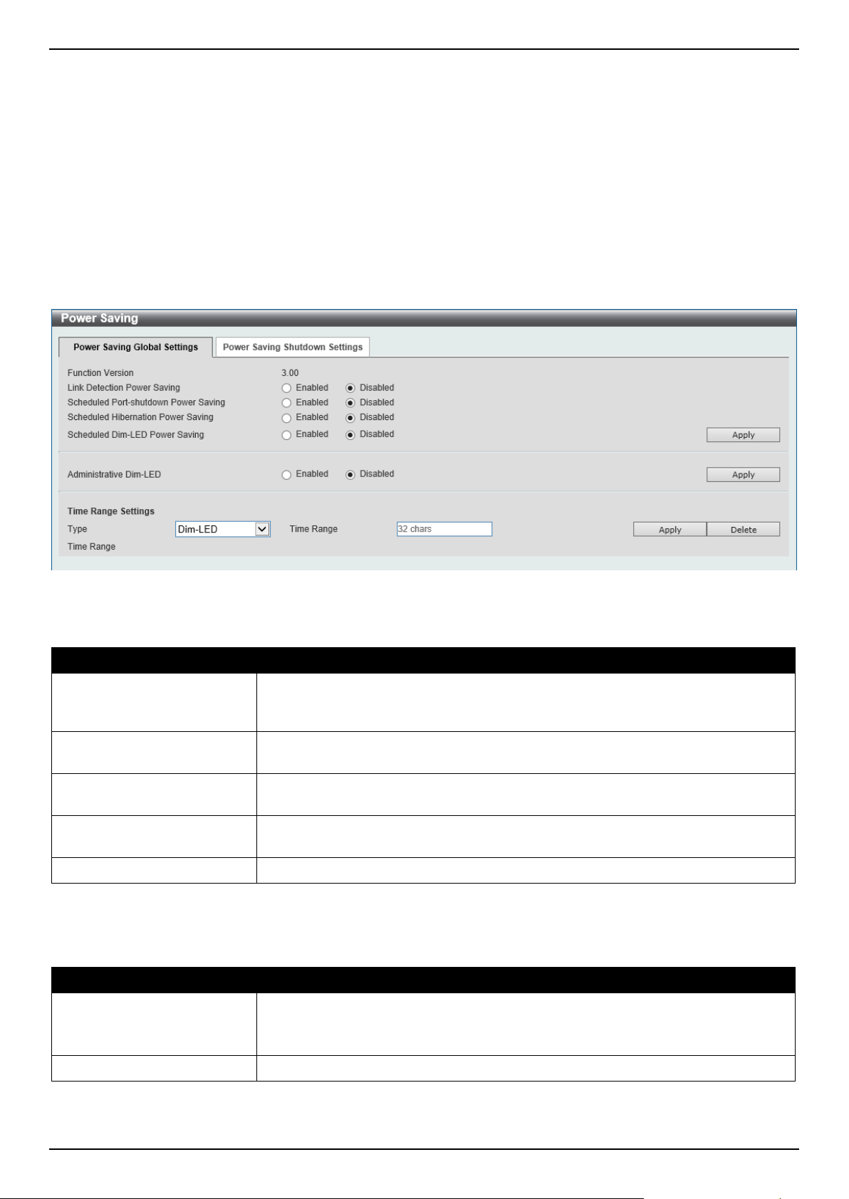
DGS-1520 Series Gigabit Ethernet Smart Managed Switch Web UI Reference Guide
513
12. Green
Power Saving
EEE
Power Saving
This window is used to display and configure the power saving settings of the Switch.
To view the following window, click Green > Power Saving and select the Power Saving Global Settings tab, as
shown below:
Figure 12-1 Power Saving Global Settings Window
The fields that can be configured in Power Saving Global Settings are described below:
Parameter Description
Link Detection Power
Saving
Select to enable or disable the link detection state. When enabled, a port, which
has a link down status, will be turned off to save power to the Switch. This will not
affect the port's capabilities when the port status is link up.
Scheduled Port-shutdown
Power Saving
Select to enable or disable applying the power saving by scheduled port shutdown.
Scheduled Hibernation
Power Saving
Select to enable or disable the scheduled hibernation power saving function here.
This function is not available when physical stacking is enabled.
Scheduled Dim-LED Power
Saving
Select to enable or disable applying the power saving by scheduled dimming
LEDs.
Administrative Dim-LED
Select to enable or disable the port LED function.
Click the Apply button to accept the changes made.
The fields that can be configured in Time Range Settings are described below:
Parameter Description
Type Select the type of power saving. Options to choose from are Dim-LED and
Hibernation.
Hibernation is not available when physical stacking is enabled.
Time Range
Enter the name of the time range to associate with the power saving type.
Click the Apply button to accept the changes made for each individual section.
Click the Delete button to remove the specified entry.
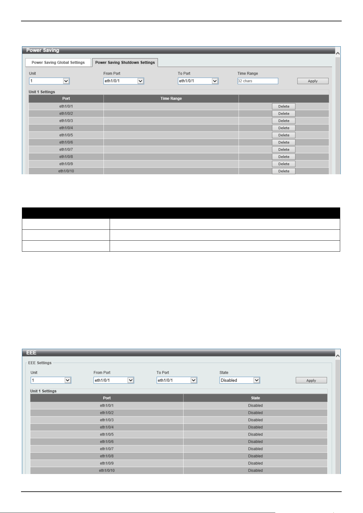
DGS-1520 Series Gigabit Ethernet Smart Managed Switch Web UI Reference Guide
514
To view the following window, select the Power Saving Shutdown Settings tab, as shown below:
Figure 12-2 Power Saving Shutdown Settings Window
The fields that can be configured are described below:
Parameter Description
Unit
Select the Switch unit that will be used for this configuration here.
From Port - To Port
Select the appropriate port range used for the configuration here.
Time Range
Enter the name of the time range to associate with the ports.
Click the Apply button to accept the changes made.
Click the Delete button to remove the specified entry.
EEE
Energy Efficient Ethernet (EEE) is defined in IEEE 802.3az. It is designed to reduce the energy consumption of a link
when no packets are being sent.
To view the following window, click Green > EEE, as shown below:
Figure 12-3 EEE Window

DGS-1520 Series Gigabit Ethernet Smart Managed Switch Web UI Reference Guide
515
The fields that can be configured are described below:
Parameter Description
Unit
Select the Switch unit that will be used for this configuration here.
From Port - To Port
Select the appropriate port range used for the configuration here.
State
Select this option to enable or disable the state of this feature here.
Click the Apply button to accept the changes made.
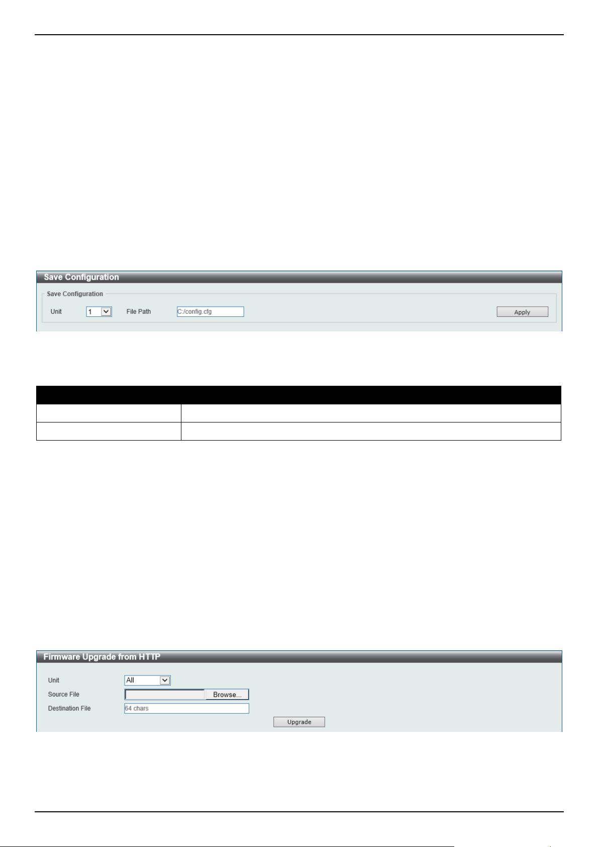
DGS-1520 Series Gigabit Ethernet Smart Managed Switch Web UI Reference Guide
516
13. Toolbar
Save
Tools
Online Help
Save
Save Configuration
This window is used to save the running configuration to the start-up configuration. This is to prevent the loss of
configuration in the event of a power failure.
To view the following window, click Save > Save Configuration, as shown below:
Figure 13-1 Save Configuration Window
The fields that can be configured are described below:
Parameter Description
Unit
Select the Switch unit that will be used for this configuration here.
File Path
Enter the filename and path in the space provided.
Click the Apply button to save the configuration.
Tools
Firmware Upgrade & Backup
Firmware Upgrade from HTTP
This window is used to initiate a firmware upgrade from a local PC using HTTP.
To view the following window, click Tools > Firmware Upgrade & Backup > Firmware Upgrade from HTTP, as
shown below:
Figure 13-2 Firmware Upgrade from HTTP Window
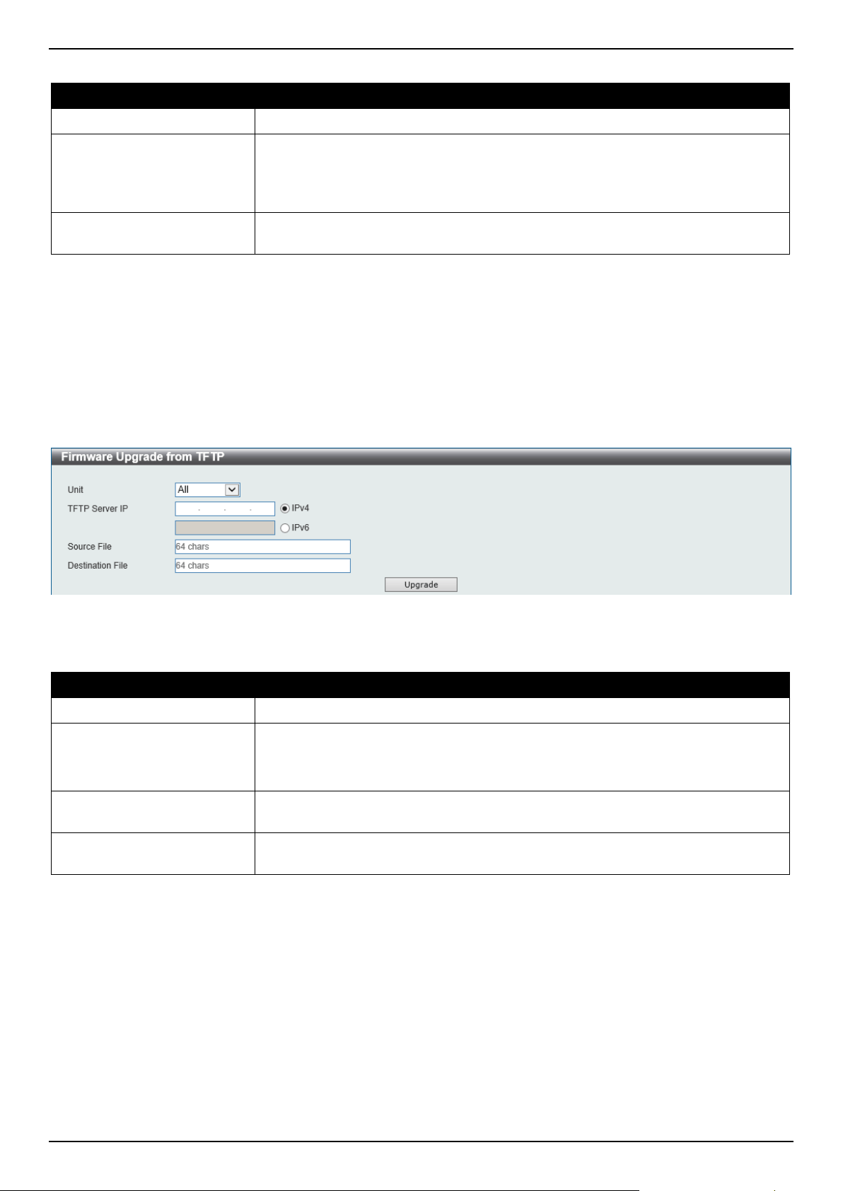
DGS-1520 Series Gigabit Ethernet Smart Managed Switch Web UI Reference Guide
517
The fields that can be configured are described below:
Parameter Description
Unit
Select the Switch unit that will be used for this configuration here.
Source File
In this field, the source firmware file's filename and path will be displayed after
selection.
To navigate to the location of the firmware file located on the local PC, either
double click in the text box or click the Browse button.
Destination File
Enter the destination path and location where the new firmware should be stored
on the Switch. This field can be up to 64 characters long.
Click the Upgrade button to initiate the firmware upgrade.
Firmware Upgrade from TFTP
This window is used to initiate a firmware upgrade from a TFTP server.
To view the following window, click Tools > Firmware Upgrade & Backup > Firmware Upgrade from TFTP, as
shown below:
Figure 13-3 Firmware Upgrade from TFTP Window
The fields that can be configured are described below:
Parameter Description
Unit
Select the Switch unit that will be used for this configuration here.
TFTP Server IP
Select and enter the IP address of the TFTP server here.
• IPv4 - Select and enter the IPv4 address of the TFTP server here.
• IPv6 - Select and enter the IPv6 address of the TFTP server here.
Source File
Enter the source filename and path of the firmware file located on the TFTP server
here. This field can be up to 64 characters long.
Destination File
Enter the destination path and location where the new firmware should be stored
on the Switch. This field can be up to 64 characters long.
Click the Upgrade button to initiate the firmware upgrade.

DGS-1520 Series Gigabit Ethernet Smart Managed Switch Web UI Reference Guide
518
Firmware Upgrade from SFTP
This window is used to initiate a firmware upgrade from an SFTP server.
To view the following window, click Tools > Firmware Upgrade & Backup > Firmware Upgrade from SFTP, as
shown below:
Figure 13-4 Firmware Upgrade from SFTP Window
The fields that can be configured are described below:
Parameter Description
Unit
Select the Switch unit that will be used for this configuration here.
SFTP Server IP
Select and enter the IP address of the SFTP server here.
• IPv4 - Select and enter the IPv4 address of the SFTP server here.
• IPv6 - Select and enter the IPv6 address of the SFTP server here.
User Name
Enter the user name used for the SFTP connection here. This name can be up to
32 characters long.
Password
Enter the password used for the SFTP connection here. This password can be up
to 15 characters long.
Source File
Enter the source filename and path of the firmware file located on the SFTP server
here. This field can be up to 64 characters long.
Destination File
Enter the destination path and location where the new firmware should be stored
on the Switch. This field can be up to 64 characters long.
Click the Upgrade button to initiate the firmware upgrade.
Firmware Backup to HTTP
This window is used to initiate a firmware backup to a local PC using HTTP.
To view the following window, click Tools > Firmware Upgrade & Backup > Firmware Backup to HTTP, as shown
below:
Figure 13-5 Firmware Backup to HTTP Window
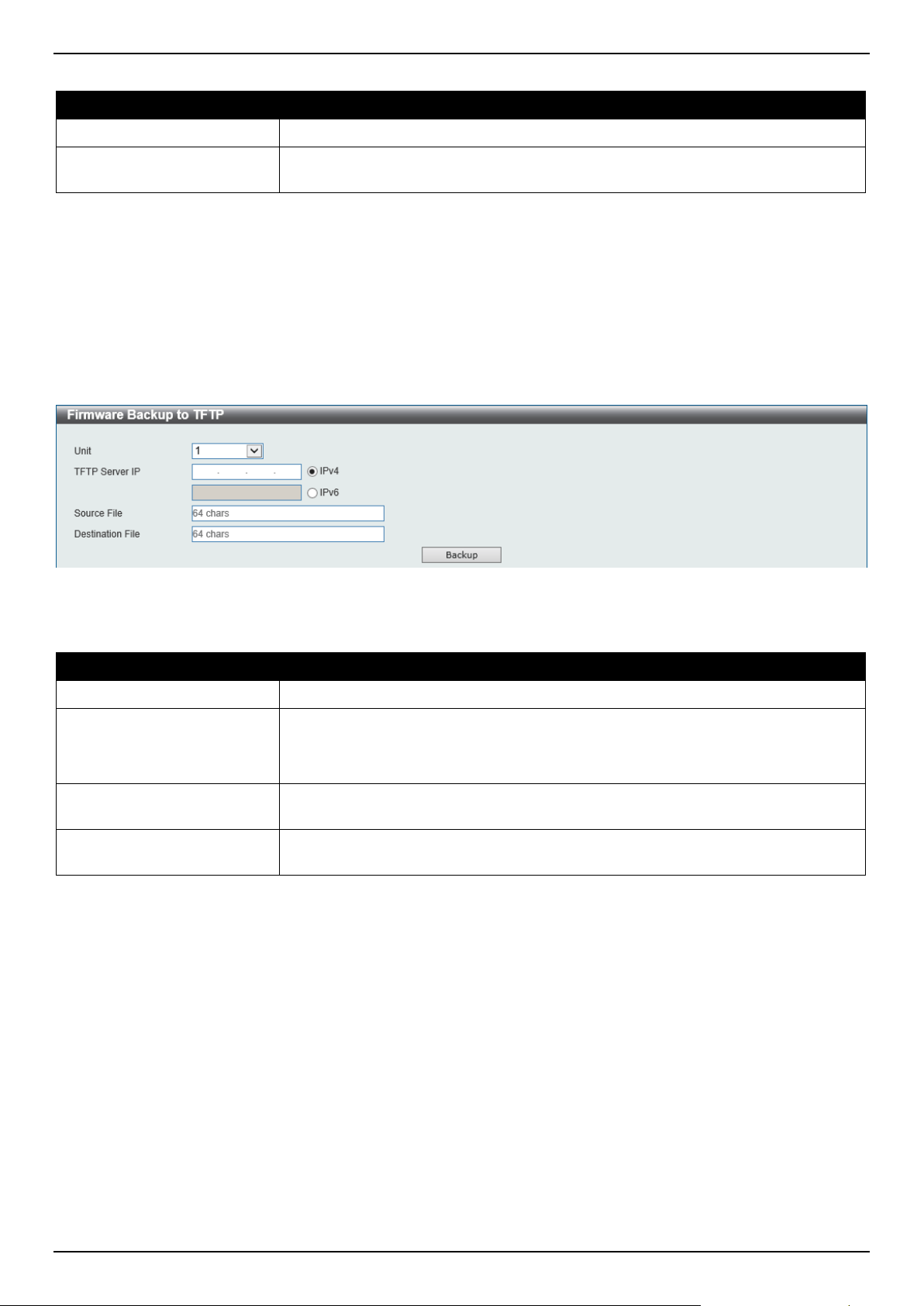
DGS-1520 Series Gigabit Ethernet Smart Managed Switch Web UI Reference Guide
519
The fields that can be configured are described below:
Parameter Description
Unit
Select the Switch unit that will be used for this configuration here.
Source File
Enter the source filename and path of the firmware file located on the Switch here.
This field can be up to 64 characters long.
Click the Backup button to initiate the firmware backup.
Firmware Backup to TFTP
This window is used to initiate a firmware backup to a TFTP server.
To view the following window, click Tools > Firmware Upgrade & Backup > Firmware Backup to TFTP, as shown
below:
Figure 13-6 Firmware Backup to TFTP Window
The fields that can be configured are described below:
Parameter Description
Unit
Select the Switch unit that will be used for this configuration here.
TFTP Server IP
Select and enter the IP address of the TFTP server here.
• IPv4 - Select and enter the IPv4 address of the TFTP server here.
• IPv6 - Select and enter the IPv6 address of the TFTP server here.
Source File
Enter the source filename and path of the firmware file located on the Switch here.
This field can be up to 64 characters long.
Destination File
Enter the destination filename and path of the firmware file to be backed up to the
TFTP server here. This field can be up to 64 characters long.
Click the Backup button to initiate the firmware backup.
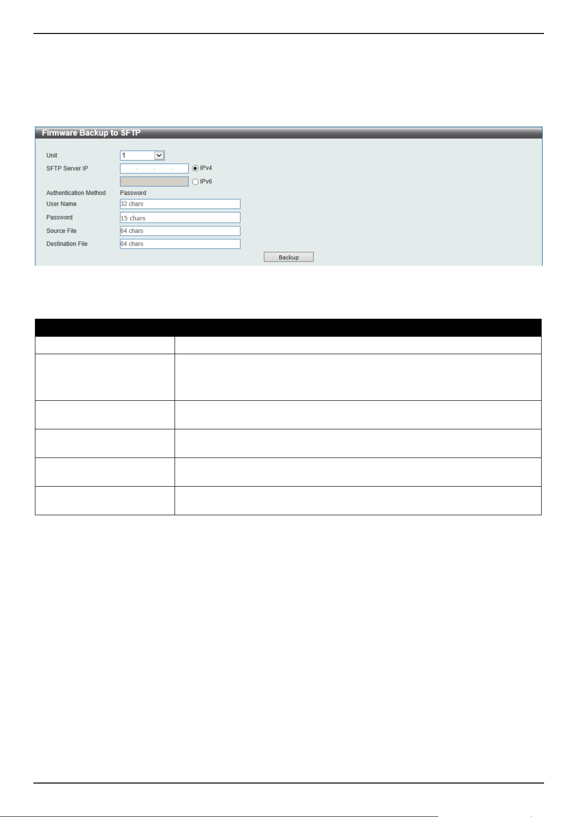
DGS-1520 Series Gigabit Ethernet Smart Managed Switch Web UI Reference Guide
520
Firmware Backup to SFTP
This window is used to initiate a firmware backup to an SFTP server.
To view the following window, click Tools > Firmware Upgrade & Backup > Firmware Backup to SFTP, as shown
below:
Figure 13-7 Firmware Backup to SFTP Window
The fields that can be configured are described below:
Parameter Description
Unit
Select the Switch unit that will be used for this configuration here.
SFTP Server IP
Select and enter the IP address of the SFTP server here.
• IPv4 - Select and enter the IPv4 address of the SFTP server here.
• IPv6 - Select and enter the IPv6 address of the SFTP server here.
User Name
Enter the user name used for the SFTP connection here. This name can be up to
32 characters long.
Password
Enter the password used for the SFTP connection here. This password can be up
to 15 characters long.
Source File
Enter the source filename and path of the firmware file located on the Switch here.
This field can be up to 64 characters long.
Destination File
Enter the destination filename and path of the firmware file to be backed up to the
SFTP server here. This field can be up to 64 characters long.
Click the Backup button to initiate the firmware backup.
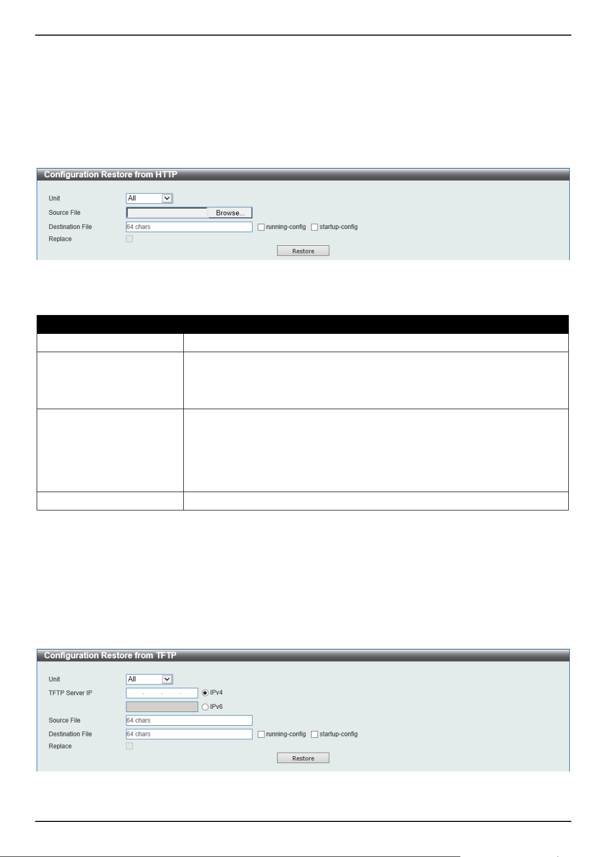
DGS-1520 Series Gigabit Ethernet Smart Managed Switch Web UI Reference Guide
521
Configuration Restore & Backup
Configuration Restore from HTTP
This window is used to initiate a configuration restore from a local PC using HTTP.
To view the following window, click Tools > Configuration Restore & Backup > Configuration Restore from HTTP,
as shown below:
Figure 13-8 Configuration Restore from HTTP Window
The fields that can be configured are described below:
Parameter Description
Unit
Select the Switch unit that will be used for this configuration here.
Source File
In this field, the source configuration file's filename and path will be displayed after
selection.
To navigate to the location of the configuration file located on the local PC, either
double click in the text box or click the Browse button.
Destination File
Enter the destination path and location where the configuration file should be
stored on the Switch. This field can be up to 64 characters long.
Select the running-config option to restore and overwrite the running
configuration file on the Switch.
Select the startup-config option to restore and overwrite the start-up configuration
file on the Switch.
Replace
Select this option to replace the configuration file on the Switch with this one.
Click the Restore button to initiate the configuration restore.
Configuration Restore from TFTP
This window is used to initiate a configuration restore from a TFTP server.
To view the following window, click Tools > Configuration Restore & Backup > Configuration Restore from TFTP,
as shown below:
Figure 13-9 Configuration Restore from TFTP Window
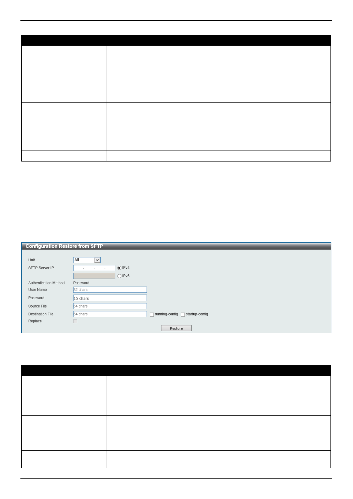
DGS-1520 Series Gigabit Ethernet Smart Managed Switch Web UI Reference Guide
522
The fields that can be configured are described below:
Parameter Description
Unit
Select the Switch unit that will be used for this configuration here.
TFTP Server IP
Select and enter the IP address of the TFTP server here.
• IPv4 - Select and enter the IPv4 address of the TFTP server here.
• IPv6 - Select and enter the IPv6 address of the TFTP server here.
Source File
Enter the source filename and path of the configuration file located on the TFTP
server here. This field can be up to 64 characters long.
Destination File
Enter the destination path and location where the configuration file should be
stored on the Switch. This field can be up to 64 characters long.
Select the running-config option to restore and overwrite the running
configuration file on the Switch.
Select the startup-config option to restore and overwrite the start-up configuration
file on the Switch.
Replace
Select this option to replace the configuration file on the Switch with this one.
Click the Restore button to initiate the configuration restore.
Configuration Restore from SFTP
This window is used to initiate a configuration restore from an SFTP server.
To view the following window, click Tools > Configuration Restore & Backup > Configuration Restore from SFTP,
as shown below:
Figure 13-10 Configuration Restore from SFTP Window
The fields that can be configured are described below:
Parameter Description
Unit
Select the Switch unit that will be used for this configuration here.
SFTP Server IP
Select and enter the IP address of the SFTP server here.
• IPv4 - Select and enter the IPv4 address of the SFTP server here.
• IPv6 - Select and enter the IPv6 address of the SFTP server here.
User Name
Enter the user name used for the SFTP connection here. This name can be up to
32 characters long.
Password
Enter the password used for the SFTP connection here. This password can be up
to 15 characters long.
Source File
Enter the source filename and path of the configuration file located on the SFTP
server here. This field can be up to 64 characters long.
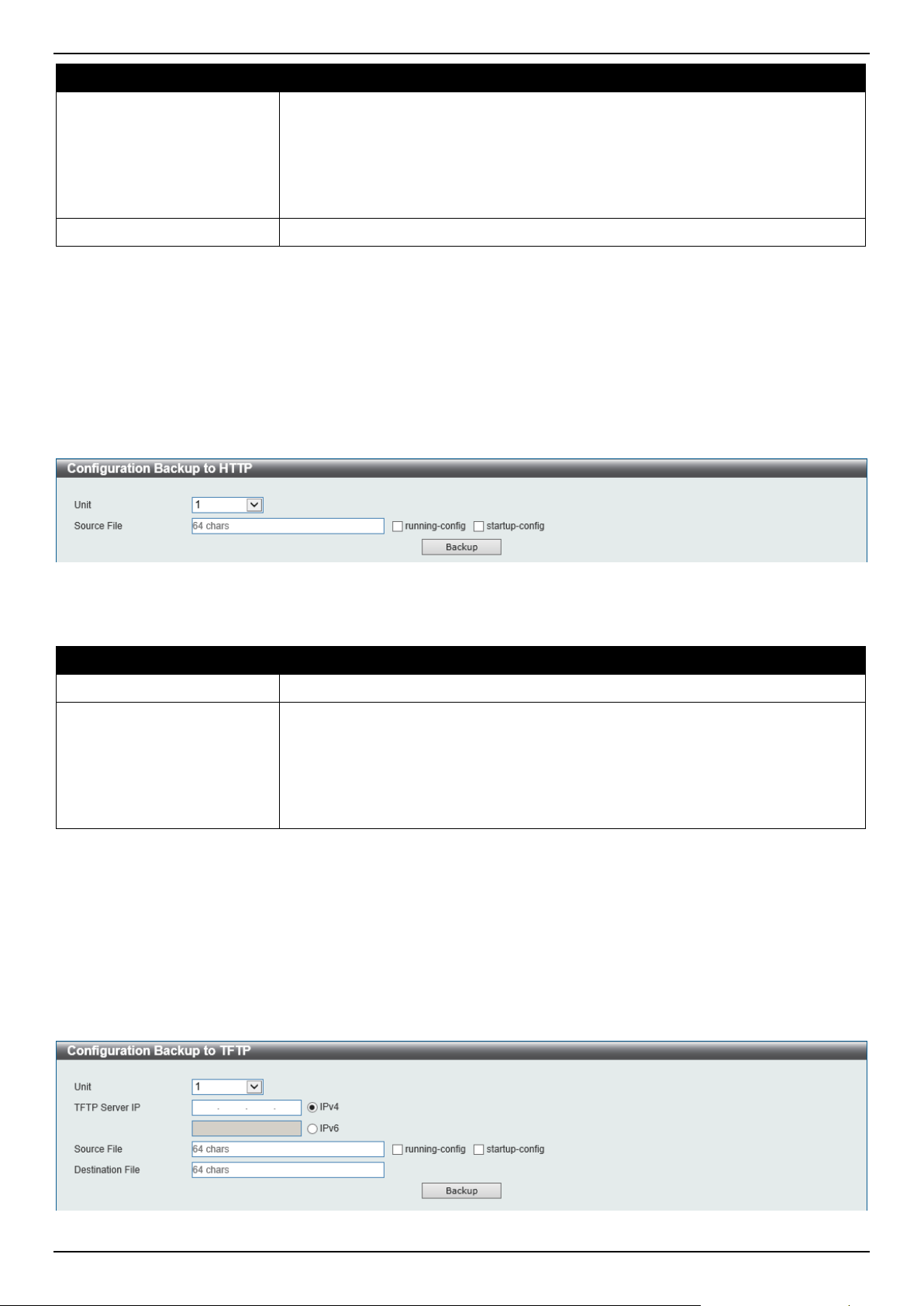
DGS-1520 Series Gigabit Ethernet Smart Managed Switch Web UI Reference Guide
523
Parameter Description
Destination File
Enter the destination path and location where the configuration file should be
stored on the Switch. This field can be up to 64 characters long.
Select the running-config option to restore and overwrite the running
configuration file on the Switch.
Select the startup-config option to restore and overwrite the start-up configuration
file on the Switch.
Replace
Select this option to replace the configuration file on the Switch with this one.
Click the Restore button to initiate the configuration restore.
Configuration Backup to HTTP
This window is used to initiate a configuration file backup to a local PC using HTTP.
To view the following window, click Tools > Configuration Restore & Backup > Configuration Backup to HTTP, as
shown below:
Figure 13-11 Configuration Backup to HTTP Window
The fields that can be configured are described below:
Parameter Description
Unit
Select the Switch unit that will be used for this configuration here.
Source File
Enter the source filename and path of the configuration file located on the Switch
here. This field can be up to 64 characters long.
Select the running-config option to back up the running configuration file from the
Switch.
Select the startup-config option to back up the start-up configuration file from the
Switch.
Click the Backup button to initiate the configuration file backup.
Configuration Backup to TFTP
This window is used to initiate a configuration file backup to a TFTP server.
To view the following window, click Tools > Configuration Restore & Backup > Configuration Backup to TFTP, as
shown below:
Figure 13-12 Configuration Backup to TFTP Window
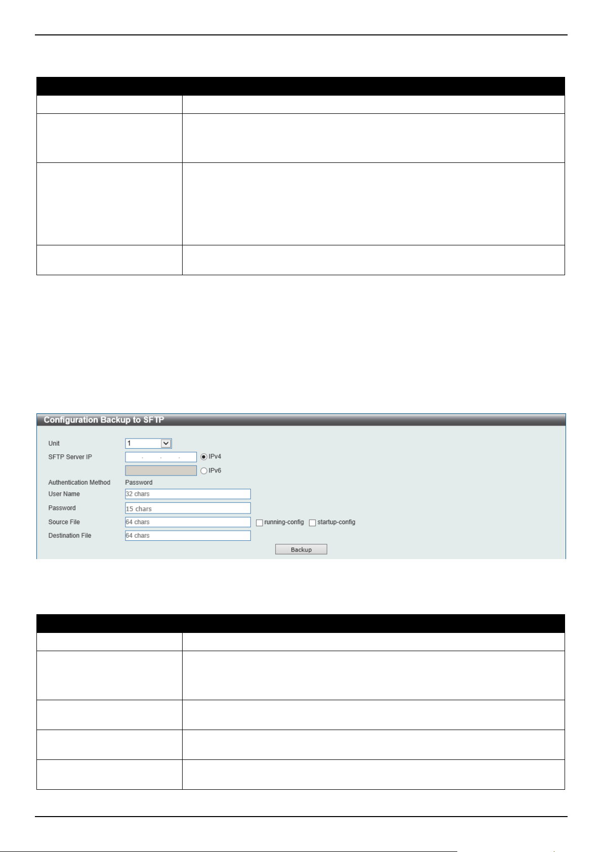
DGS-1520 Series Gigabit Ethernet Smart Managed Switch Web UI Reference Guide
524
The fields that can be configured are described below:
Parameter Description
Unit
Select the Switch unit that will be used for this configuration here.
TFTP Server IP
Select and enter the IP address of the TFTP server here.
• IPv4 - Select and enter the IPv4 address of the TFTP server here.
• IPv6 - Select and enter the IPv6 address of the TFTP server here.
Source File
Enter the source filename and path of the configuration file located on the Switch
here. This field can be up to 64 characters long.
Select the running-config option to back up the running configuration file from the
Switch.
Select the startup-config option to back up the start-up configuration file from the
Switch.
Destination File
Enter the destination path and location where the configuration file should be
stored on the TFTP server. This field can be up to 64 characters long.
Click the Backup button to initiate the configuration file backup.
Configuration Backup to SFTP
This window is used to initiate a configuration file backup to an SFTP server.
To view the following window, click Tools > Configuration Restore & Backup > Configuration Backup to SFTP, as
shown below:
Figure 13-13 Configuration Backup to SFTP Window
The fields that can be configured are described below:
Parameter Description
Unit
Select the Switch unit that will be used for this configuration here.
SFTP Server IP
Select and enter the IP address of the SFTP server here.
• IPv4 - Select and enter the IPv4 address of the SFTP server here.
• IPv6 - Select and enter the IPv6 address of the SFTP server here.
User Name
Enter the user name used for the SFTP connection here. This name can be up to
32 characters long.
Password
Enter the password used for the SFTP connection here. This password can be up
to 15 characters long.
Source File
Enter the source filename and path of the configuration file located on the Switch
here. This field can be up to 64 characters long.
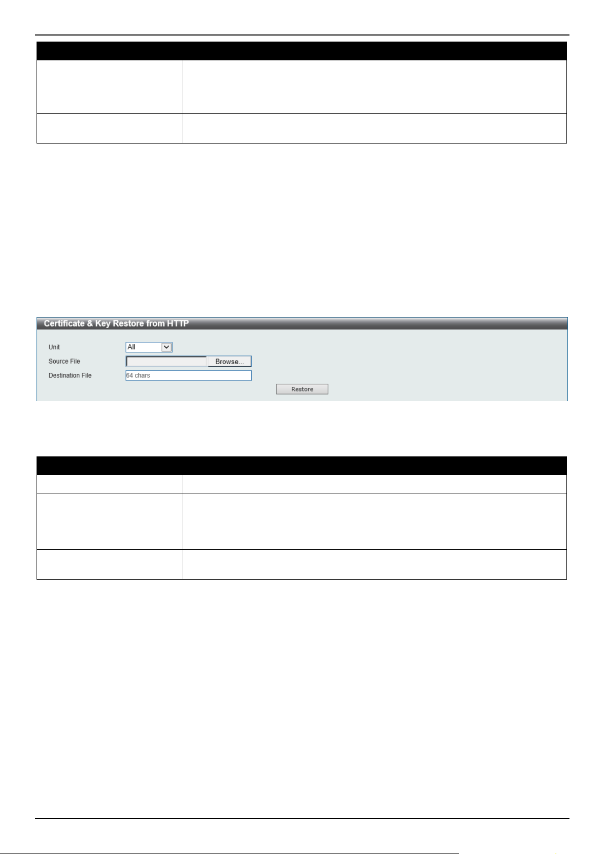
DGS-1520 Series Gigabit Ethernet Smart Managed Switch Web UI Reference Guide
525
Parameter Description
Select the running-config option to back up the running configuration file from the
Switch.
Select the startup-config option to back up the start-up configuration file from the
Switch.
Destination File
Enter the destination path and location where the configuration file should be
stored on the SFTP server. This field can be up to 64 characters long.
Click the Backup button to initiate the configuration file backup.
Certificate & Key Restore & Backup
Certificate & Key Restore from HTTP
This window is used to initiate a certificate and key restore from a local PC using HTTP.
To view the following window, click Tools > Certificate & Key Restore & Backup > Certificate & Key Restore from
HTTP, as shown below:
Figure 13-14 Certificate & Key Restore from HTTP Window
The fields that can be configured are described below:
Parameter Description
Unit
Select the Switch unit that will be used for this configuration here.
Source File
In this field, the source certificate and key file's filename and path will be displayed
after selection.
To navigate to the location of the certificate and key file located on the local PC,
either double click in the text box or click the Browse button.
Destination File
Enter the destination path and location where the new certificate and key should
be stored on the Switch. This field can be up to 64 characters long.
Click the Restore button to initiate the certificate and key restore.
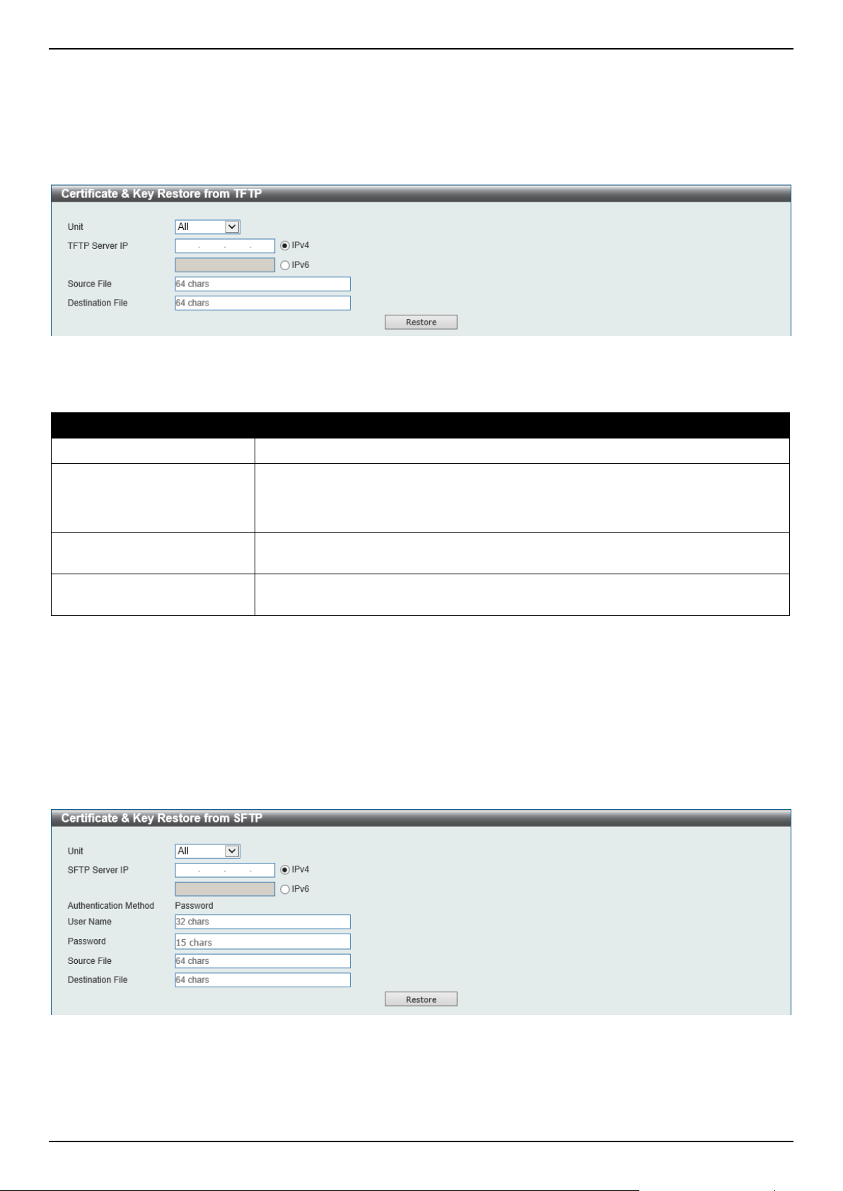
DGS-1520 Series Gigabit Ethernet Smart Managed Switch Web UI Reference Guide
526
Certificate & Key Restore from TFTP
This window is used to initiate a certificate and key restore from a TFTP server.
To view the following window, click Tools > Certificate & Key Restore & Backup > Certificate & Key Restore from
TFTP, as shown below:
Figure 13-15 Certificate & Key Restore from TFTP Window
The fields that can be configured are described below:
Parameter Description
Unit
Select the Switch unit that will be used for this configuration here.
TFTP Server IP
Select and enter the IP address of the TFTP server here.
• IPv4 - Select and enter the IPv4 address of the TFTP server here.
• IPv6 - Select and enter the IPv6 address of the TFTP server here.
Source File
Enter the source filename and path of the certificate and key file located on the
TFTP server here. This field can be up to 64 characters long.
Destination File
Enter the destination path and location where the new certificate and key should
be stored on the Switch. This field can be up to 64 characters long.
Click the Restore button to initiate the certificate and key restore.
Certificate & Key Restore from SFTP
This window is used to initiate a certificate and key restore from an SFTP server.
To view the following window, click Tools > Certificate & Key Restore & Backup > Certificate & Key Restore from
SFTP, as shown below:
Figure 13-16 Certificate & Key Restore from SFTP Window
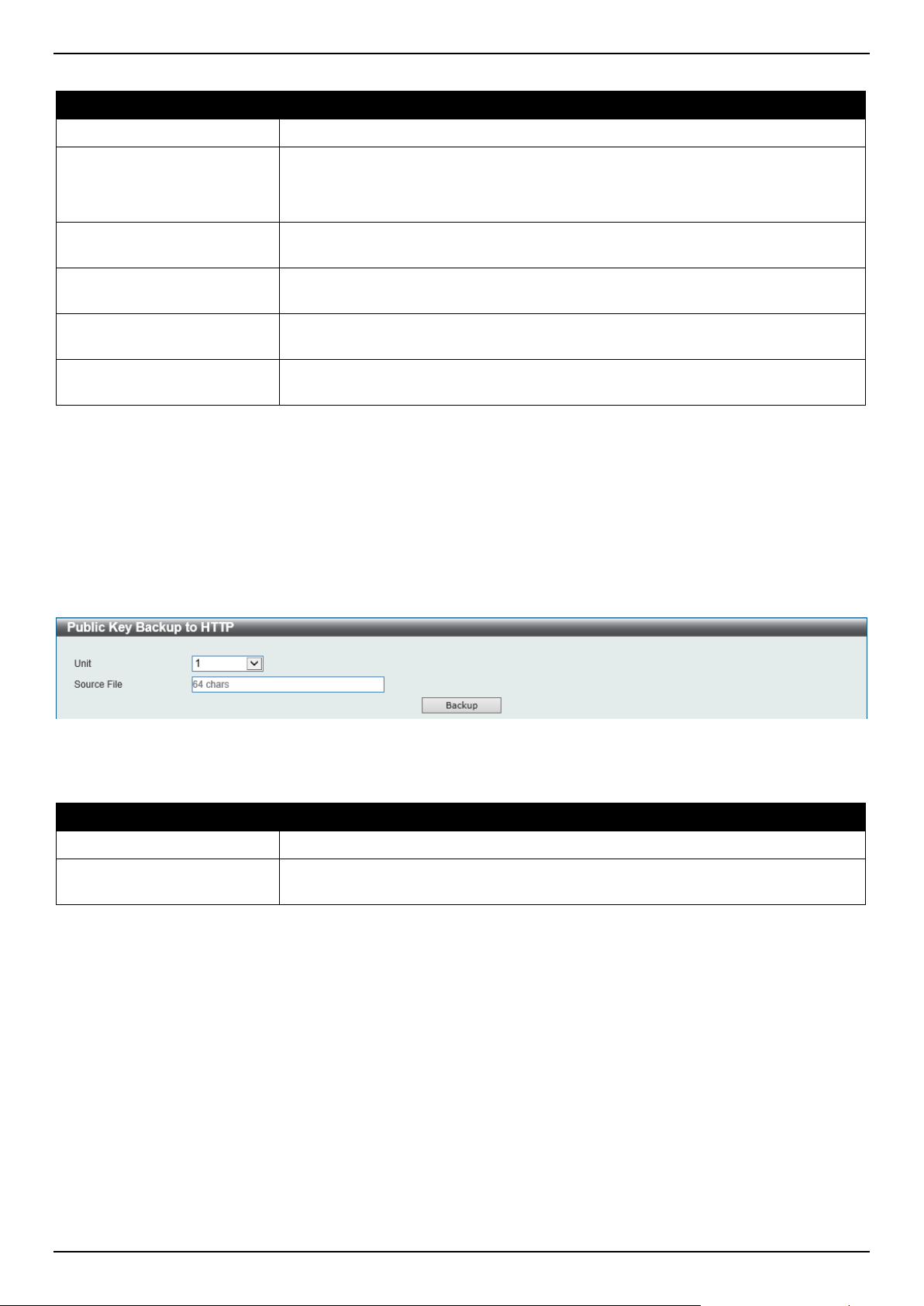
DGS-1520 Series Gigabit Ethernet Smart Managed Switch Web UI Reference Guide
527
The fields that can be configured are described below:
Parameter Description
Unit
Select the Switch unit that will be used for this configuration here.
SFTP Server IP
Select and enter the IP address of the SFTP server here.
• IPv4 - Select and enter the IPv4 address of the SFTP server here.
• IPv6 - Select and enter the IPv6 address of the SFTP server here.
User Name
Enter the user name used for the SFTP connection here. This name can be up to
32 characters long.
Password
Enter the password used for the SFTP connection here. This password can be up
to 15 characters long.
Source File
Enter the source filename and path of the certificate and key file located on the
SFTP server here. This field can be up to 64 characters long.
Destination File
Enter the destination path and location where the new certificate and key should
be stored on the Switch. This field can be up to 64 characters long.
Click the Restore button to initiate the certificate and key restore.
Certificate & Key Backup to HTTP
This window is used to initiate a certificate and key backup to a local PC using HTTP.
To view the following window, click Tools > Certificate & Key Upgrade & Backup > Certificate & Key Backup to
HTTP, as shown below:
Figure 13-17 Certificate & Key Backup to HTTP Window
The fields that can be configured are described below:
Parameter Description
Unit
Select the Switch unit that will be used for this configuration here.
Source File
Enter the source filename and path of the certificate and key file located on the
Switch here. This field can be up to 64 characters long.
Click the Backup button to initiate the certificate and key backup.
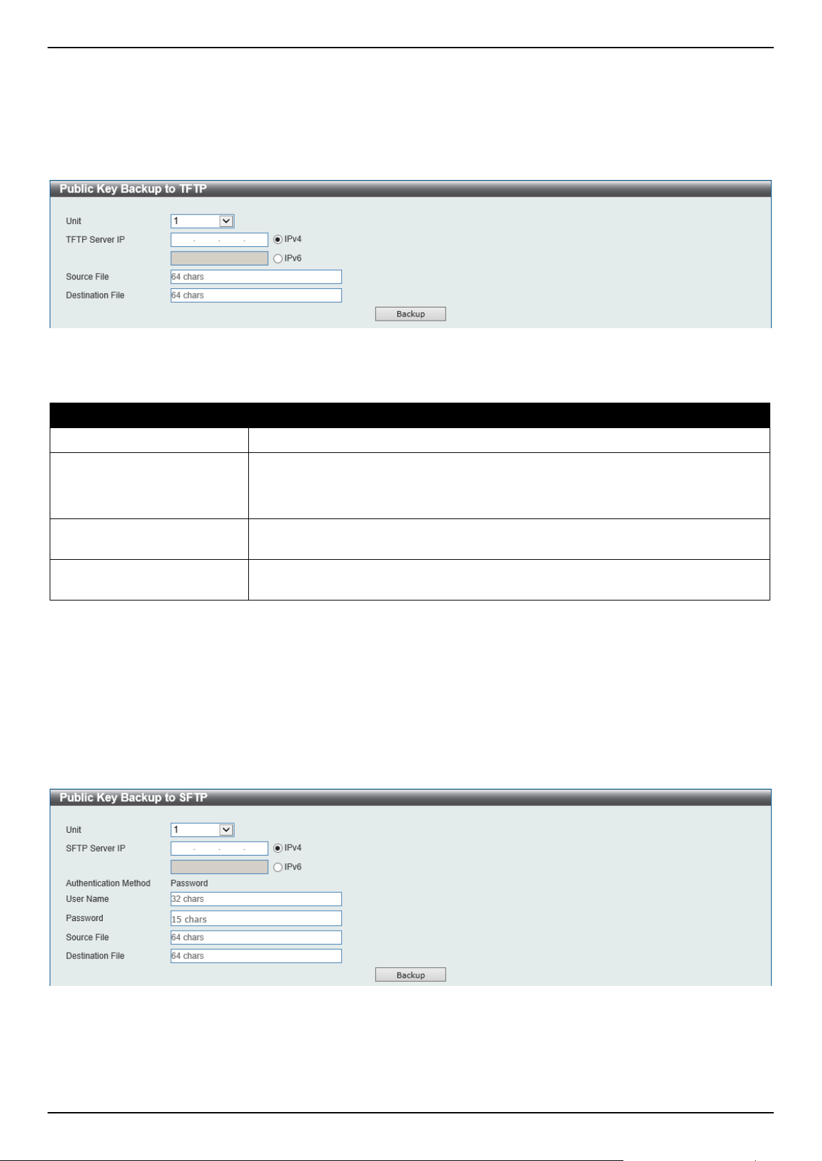
DGS-1520 Series Gigabit Ethernet Smart Managed Switch Web UI Reference Guide
528
Certificate & Key Backup to TFTP
This window is used to initiate a certificate and key backup to a TFTP server.
To view the following window, click Tools > Certificate & Key Upgrade & Backup > Certificate & Key Backup to
TFTP, as shown below:
Figure 13-18 Certificate & Key Backup to TFTP Window
The fields that can be configured are described below:
Parameter Description
Unit
Select the Switch unit that will be used for this configuration here.
TFTP Server IP
Select and enter the IP address of the TFTP server here.
• IPv4 - Select and enter the IPv4 address of the TFTP server here.
• IPv6 - Select and enter the IPv6 address of the TFTP server here.
Source File
Enter the source filename and path of the certificate and key file located on the
Switch here. This field can be up to 64 characters long.
Destination File
Enter the destination filename and path of the certificate and key file to be backed
up to the TFTP server here. This field can be up to 64 characters long.
Click the Backup button to initiate the certificate and key backup.
Certificate & Key Backup to SFTP
This window is used to initiate a certificate and key backup to an SFTP server.
To view the following window, click Tools > Certificate & Key Upgrade & Backup > Certificate & Key Backup to
SFTP, as shown below:
Figure 13-19 Certificate & Key Backup to SFTP Window
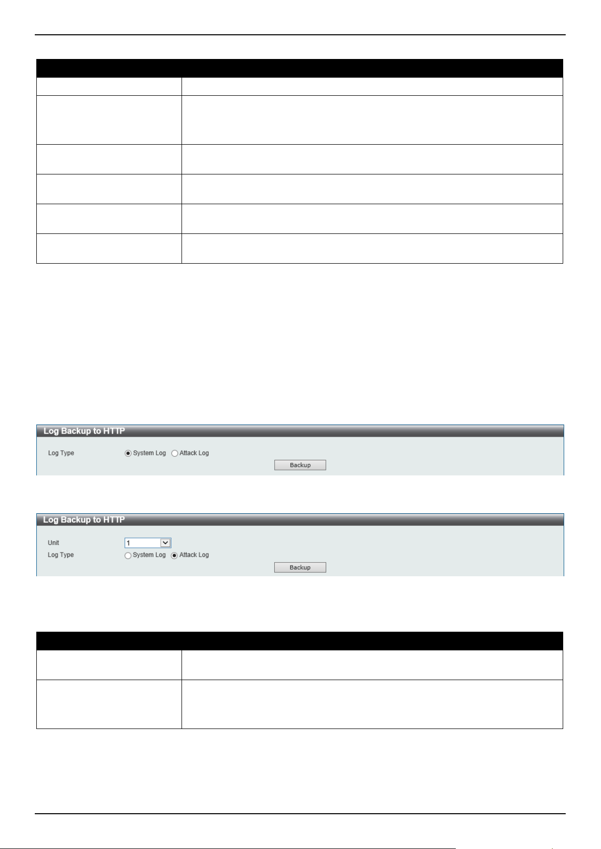
DGS-1520 Series Gigabit Ethernet Smart Managed Switch Web UI Reference Guide
529
The fields that can be configured are described below:
Parameter Description
Unit
Select the Switch unit that will be used for this configuration here.
SFTP Server IP
Select and enter the IP address of the SFTP server here.
• IPv4 - Select and enter the IPv4 address of the SFTP server here.
• IPv6 - Select and enter the IPv6 address of the SFTP server here.
User Name
Enter the user name used for the SFTP connection here. This name can be up to
32 characters long.
Password
Enter the password used for the SFTP connection here. This password can be up
to 15 characters long.
Source File
Enter the source filename and path of the certificate and key file located on the
Switch here. This field can be up to 64 characters long.
Destination File
Enter the destination filename and path of the certificate and key file to be backed
up to the SFTP server here. This field can be up to 64 characters long.
Click the Backup button to initiate the certificate and key backup.
Log Backup
Log Backup to HTTP
This window is used to initiate a system log backup to a local PC using HTTP.
To view the following window, click Tools > Log Backup > Log Backup to HTTP, as shown below:
Figure 13-20 Log Backup to HTTP (System Log) Window
Figure 13-21 Log Backup to HTTP (Attack Log) Window
The fields that can be configured are described below:
Parameter Description
Unit
Select the Switch unit that will be used for this configuration here. This is only
available when Attack Log is selected.
Log Type
Select the log type that will be backed up to the local PC using HTTP.
• System Log - Specifies that the system log will be backed up.
• Attack Log - Specifies that the attack log will be backed up.
Click the Backup button to initiate the system log backup.
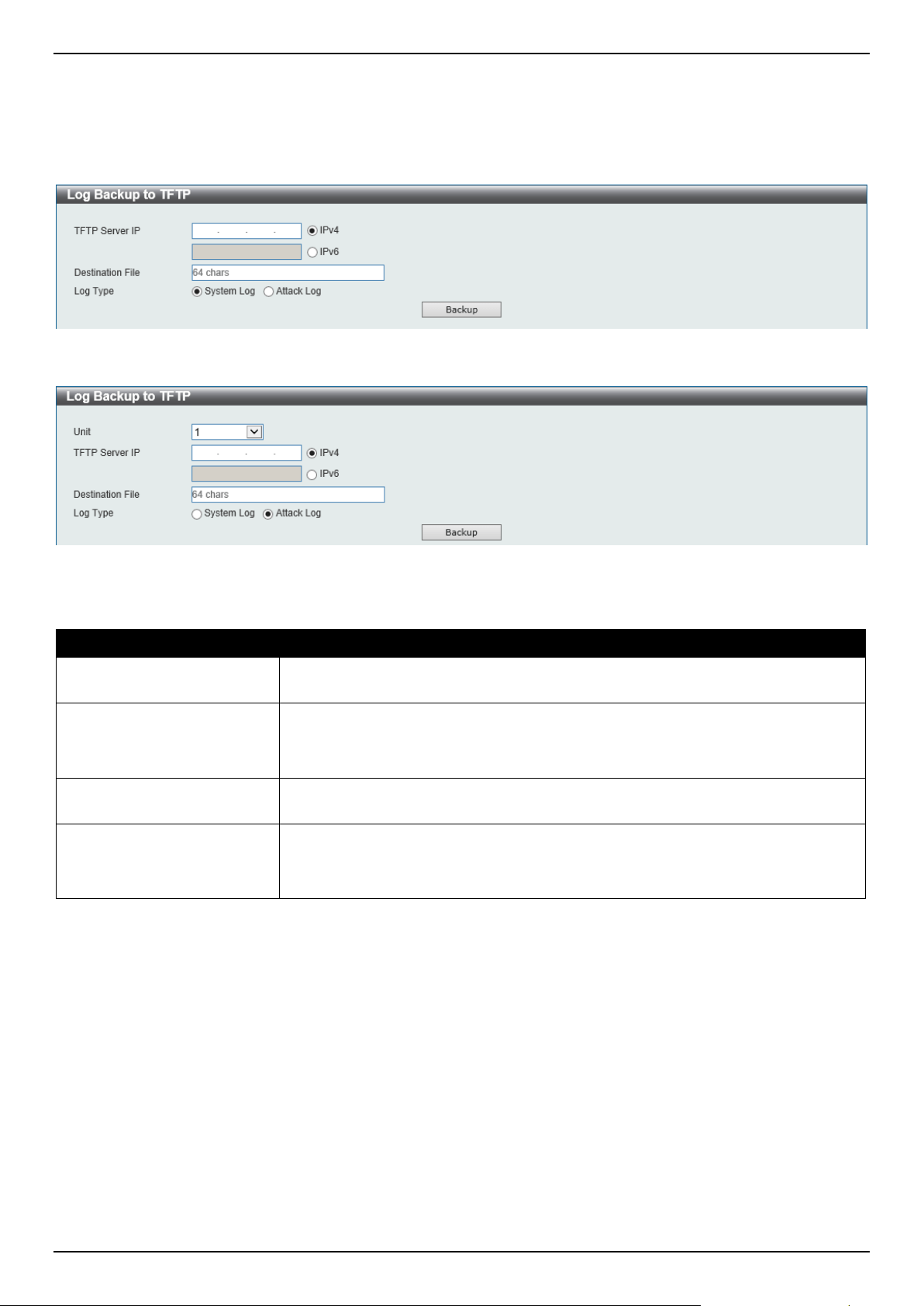
DGS-1520 Series Gigabit Ethernet Smart Managed Switch Web UI Reference Guide
530
Log Backup to TFTP
This window is used to initiate a system log backup to a TFTP server.
To view the following window, click Tools > Log Backup > Log Backup to TFTP, as shown below:
Figure 13-22 Log Backup to TFTP (System Log) Window
Figure 13-23 Log Backup to TFTP (Attack Log) Window
The fields that can be configured are described below:
Parameter Description
Unit
Select the Switch unit that will be used for this configuration here. This is only
available when Attack Log is selected.
TFTP Server IP
Select and enter the IP address of the TFTP server here.
• IPv4 - Select and enter the IPv4 address of the TFTP server here.
• IPv6 - Select and enter the IPv6 address of the TFTP server here.
Destination File
Enter the destination path and location where the log file should be stored on the
TFTP server. This field can be up to 64 characters long.
Log Type
Select the log type that will be backed up to the TFTP server.
• System Log - Specifies that the system log will be backed up.
• Attack Log - Specifies that the attack log will be backed up.
Click the Backup button to initiate the system log backup.
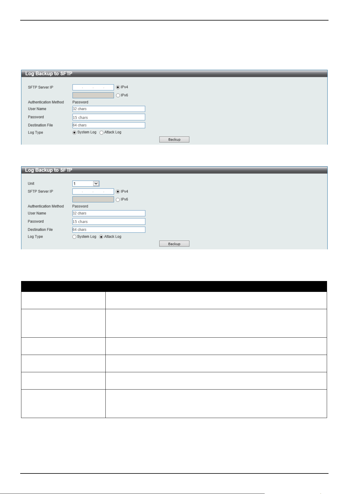
DGS-1520 Series Gigabit Ethernet Smart Managed Switch Web UI Reference Guide
531
Log Backup to SFTP
This window is used to initiate a system log backup to an SFTP server.
To view the following window, click Tools > Log Backup > Log Backup to SFTP, as shown below:
Figure 13-24 Log Backup to SFTP (System Log) Window
Figure 13-25 Log Backup to SFTP (Attack Log) Window
The fields that can be configured are described below:
Parameter Description
Unit
Select the Switch unit that will be used for this configuration here. This is only
available when Attack Log is selected.
SFTP Server IP
Select and enter the IP address of the SFTP server here.
• IPv4 - Select and enter the IPv4 address of the SFTP server here.
• IPv6 - Select and enter the IPv6 address of the SFTP server here.
User Name
Enter the user name used for the SFTP connection here. This name can be up to
32 characters long.
Password
Enter the password used for the SFTP connection here. This password can be up
to 15 characters long.
Destination File
Enter the destination path and location where the log file should be stored on the
SFTP server. This field can be up to 64 characters long.
Log Type
Select the log type that will be backed up to the SFTP server.
• System Log - Specifies that the system log will be backed up.
• Attack Log - Specifies that the attack log will be backed up.
Click the Backup button to initiate the system log backup.
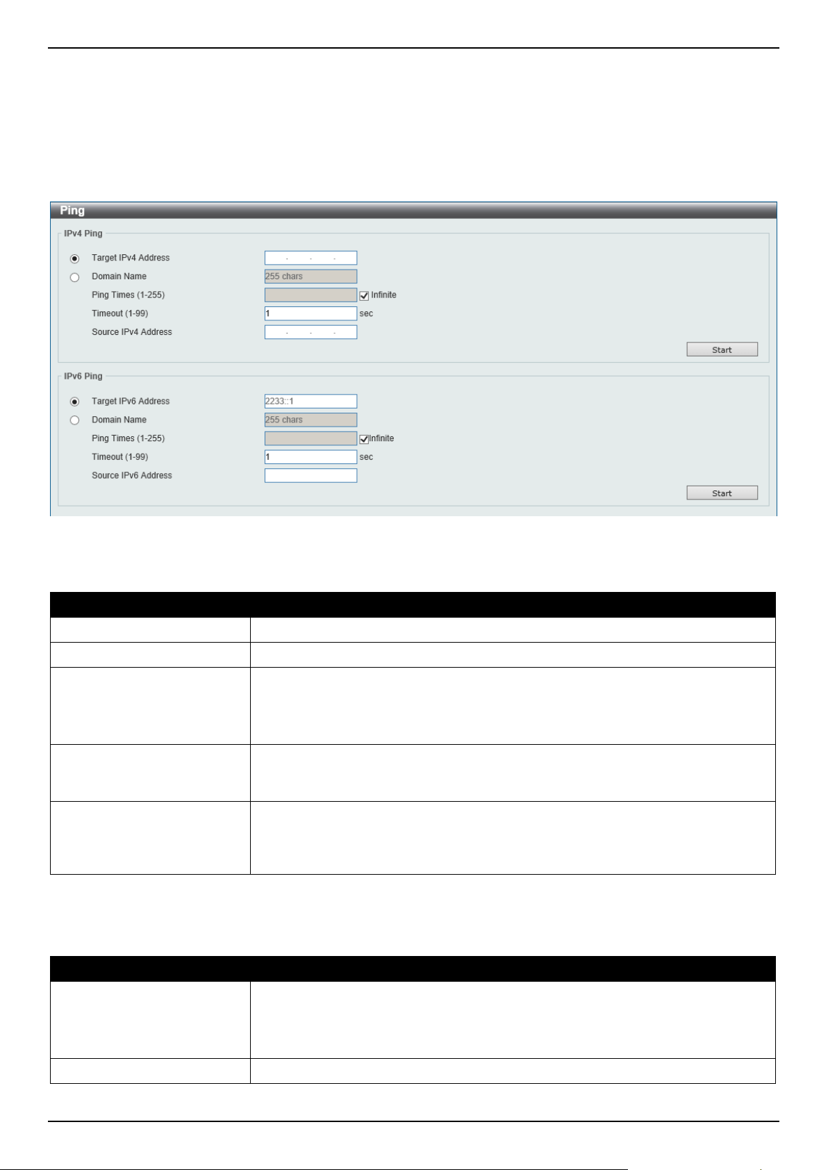
DGS-1520 Series Gigabit Ethernet Smart Managed Switch Web UI Reference Guide
532
Ping
Ping is a small program that sends ICMP Echo packets to the IP address you specify. The destination node then
responds to or "echoes" the packets sent from the Switch. This is very useful to verify connectivity between the Switch
and other nodes on the network.
To view the following window, click Tools > Ping, as shown below:
Figure 13-26 Ping Window
The fields that can be configured in IPv4 Ping are described below:
Parameter Description
Target IPv4 Address
Select and enter the IPv4 address to be pinged.
Domain Name
Select and enter the domain name of the system to discover.
Ping Times
Enter the number of times desired to attempt to Ping the IPv4 address configured
in this window. Users may enter a number of times between 1 and 255.
Tick the Infinite check box to keep sending ICMP Echo packets to the specified IP
address until the program is stopped.
Timeout
Select a timeout period between 1 and 99 seconds for this Ping message to reach
its destination. If the packet fails to find the IP address in this specified time, the
Ping packet will be dropped.
Source IPv4 Address
Enter the source IPv4 address. If the current Switch has more than one IP
address, you can enter one of them to this field. When entered, this IPv4 address
will be used as the packets' source IP address sent to the remote host, or as
primary IP address.
Click the Start button to initiate the Ping Test for each individual section.
The fields that can be configured in IPv6 Ping are described below:
Parameter Description
Target IPv6 Address
Select and enter the IPv6 address to be pinged. If the IPv6 address is a link-local
address or a multicast address, the IP interface name needs to be specified in the
following format: IPV6-ADDRESS%INTERFACE-ID.
For example, ff02::1%vlan110.
Domain Name
Select and enter the domain name of the system to discover.
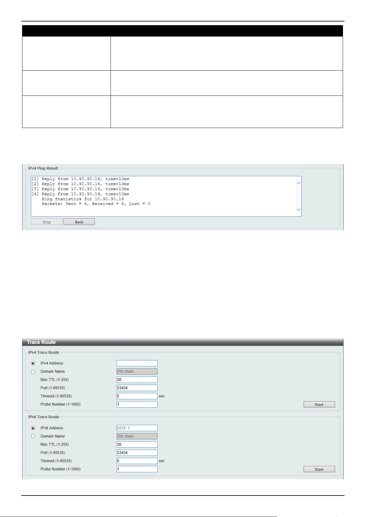
DGS-1520 Series Gigabit Ethernet Smart Managed Switch Web UI Reference Guide
533
Parameter Description
Ping Times
Enter the number of times desired to attempt to Ping the IPv6 address configured
in this window. Users may enter a number of times between 1 and 255.
Tick the Infinite check box to keep sending ICMPv6 Echo packets to the specified
IPv6 address until the program is stopped.
Timeout
Select a timeout period between 1 and 99 seconds for this Ping message to reach
its destination. If the packet fails to find the IPv6 address in this specified time, the
Ping packet will be dropped.
Source IPv6 Address
Enter the source IPv6 address. If the current Switch has more than one IPv6
address, you can enter one of them to this field. When entered, this IPv6 address
will be used as the packets' source IPv6 address sent to the remote host, or as
primary IPv6 address.
Click the Start button to initiate the Ping Test for each individual section.
After clicking the Start button in IPv4 Ping section, the following IPv4 Ping Result section will appear:
Figure 13-27 Ping (Start) Window
Click the Stop button to halt the Ping Test.
Click the Back button to return to the IPv4 Ping section.
Trace Route
The trace route page allows the user to trace a route between the Switch and a given host on the network.
To view the following window, click Tools > Trace Route, as shown below:
Figure 13-28 Trace Route Window

DGS-1520 Series Gigabit Ethernet Smart Managed Switch Web UI Reference Guide
534
The fields that can be configured in IPv4 Trace Route are described below:
Parameter Description
IPv4 Address
Select and enter the IPv4 address of the destination here.
Domain Name
Select and enter the domain name of the destination here.
Max TTL
Enter the Time-To-Live (TTL) value of the trace route request here. This is the
maximum number of routers that a trace route packet can pass. The trace route
option will cross while seeking the network path between two devices. The range
for the TTL is 1 to 255 hops.
Port
Enter the port number here. The value range is from 1 to 65535.
Timeout
Enter the timeout period while waiting for a response from the remote device here.
A value of 1 to 65535 seconds can be specified. By default, this value is 5
seconds.
Probe Number
Enter the probe time number here. The range is from 1 to 1000. By default, this
value is 1.
Click the Start button to initiate the route trace for each individual section.
The fields that can be configured in IPv6 Trace Route are described below:
Parameter Description
IPv6 Address
Select and enter the IPv6 address of the destination here.
Domain Name
Select and enter the domain name of the destination here.
Max TTL
Enter the Time-To-Live (TTL) value of the trace route request here. This is the
maximum number of routers that a trace route packet can pass. The trace route
option will cross while seeking the network path between two devices. The range
for the TTL is 1 to 255 hops.
Port
Enter the port number here. The value range is from 1 to 65535.
Timeout
Enter the timeout period while waiting for a response from the remote device here.
A value of 1 to 65535 seconds can be specified. By default, this value is 5
seconds.
Probe Number
Enter the probe time number here. The range is from 1 to 1000. By default, this
value is 1.
Click the Start button to initiate the route trace for each individual section.
After clicking the Start button in IPv4 Trace Route section, the following IPv4 Trace Route Result section will
appear:
Figure 13-29 Trace Route (Start) Window
Click the Back button to stop the trace route and return to the IPv4 Trace Route section.
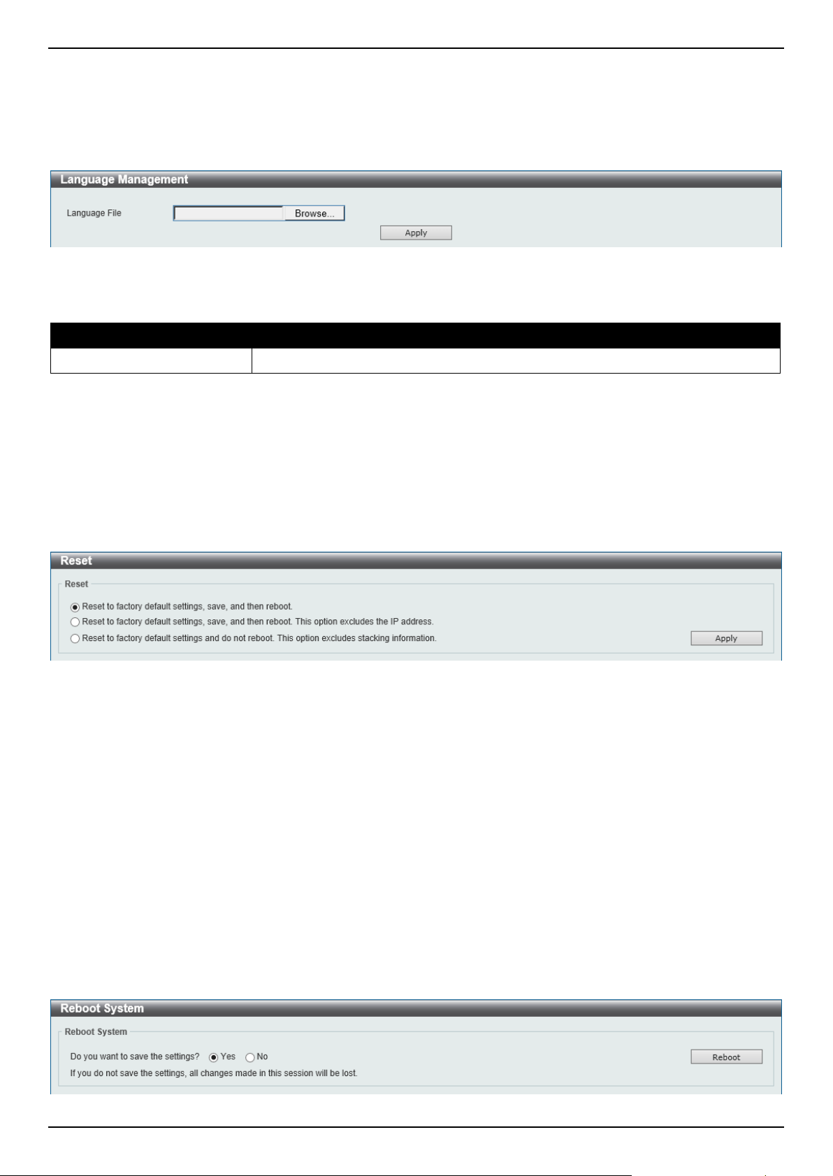
DGS-1520 Series Gigabit Ethernet Smart Managed Switch Web UI Reference Guide
535
Language Management
This window is used to install the language file to the Switch.
To view the following window, click Tools > Language Management, as shown below:
Figure 13-30 Language Management Window
The fields that can be configured are described below:
Parameter Description
Language File Click the Browse button to navigate to the language file on the local PC.
Click the Apply button to install the new language pack.
Reset
This window is used to reset the Switch's configuration to the factory default settings.
To view the following window, click Tools > Reset, as shown below:
Figure 13-31 Reset Window
Select one of the following options:
• Reset to factory default settings, save, and then reboot.
• Reset to factory default settings, save, and then reboot. This option excludes the IP address.
• Reset to factory default settings and do not reboot. This option excludes stacking information.
Click the Apply button to initiate the reset.
Reboot System
This window is used to reboot the Switch and alternatively save the configuration before doing so.
To view the following window, click Tools > Reboot System, as shown below:
Figure 13-32 Reboot System Window
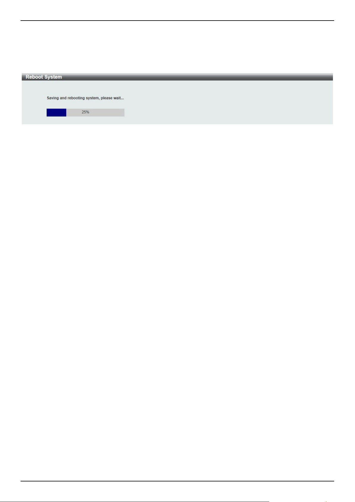
DGS-1520 Series Gigabit Ethernet Smart Managed Switch Web UI Reference Guide
536
When rebooting the Switch, any configuration changes that was made during this session, will be lost unless the Yes
option is selected when asked to save the settings.
Click the Reboot button to alternatively save the settings and reboot the Switch.
Figure 13-33 Reboot System (Rebooting) Window
Wizard
Click this option to start the Smart Wizard. For more information about the Smart Wizard, refer to Smart Wizard on
page 3.
Online Help
D-Link Support Site
Click this option to connect to the D-Link support website. An Internet connection is required.
User Guide
Click this option to connect to the online user guide for the Switch. An Internet connection is required.

DGS-1520 Series Gigabit Ethernet Smart Managed Switch Web UI Reference Guide
537
Appendix A - Password Recovery Procedure
This section describes the procedure for resetting passwords on the D-Link DGS-1520 Series Switch.
Authenticating any user who tries to access networks is necessary and important. The basic authentication method
used to accept qualified users is through a local login, utilizing a Username and Password. Sometimes, passwords will
be forgotten or destroyed, so network administrators need to reset these passwords. This section will explain how the
Password Recovery feature can help network administrators reach this goal.
The following steps explain how to use the Password Recovery feature on this Switch to easily recover passwords.
Complete these steps to reset the password:
• For security reasons, the Password Recovery feature requires the user to physically access the device.
Therefore, this feature is only applicable when there is a direct connection to the console port of the device. It is
necessary for the user needs to attach a terminal or PC with terminal emulation to the console port of the
Switch.
• Power on the Switch. After the UART init is loaded to 100%, the Switch will allow 2 seconds for the user to
press the hotkey [^] (Shift+6) to enter the "Password Recovery Mode." Once the Switch enters the "Password
Recovery Mode," all ports on the Switch will be disabled.
Boot Procedure 1.00.007
-------------------------------------------------------------------------------
Power On Self Test ........................................ 100 %
MAC Address : 80-26-89-15-28-00
H/W Version : A1
Please Wait, Loading V1.00.017 Runtime Image .............. 100 %
UART init ................................................. 100 %
Password Recovery Mode
Switch(reset-config)#
In the Password Recovery Mode, only the following commands can be used.
Command Description
no enable password
This command is used to delete all account level passwords.
no login password
This command is used to clear the local login methods.
no username
This command is used to delete all local user accounts.
password-recovery
This command is used to initiate the password recovery procedure.
reload
This command is used to save and reboot the Switch.
reload clear running-
config
This command is used to reset the running configuration to the factory default
settings and then reboot the Switch.
show running-config
This command is used to display the current running configuration.
show username
This command is used to display local user account information.

DGS-1520 Series Gigabit Ethernet Smart Managed Switch Web UI Reference Guide
538
Appendix B - System Log Entries
The System Log entries are listed in this appendix.
802.1X
Log Description Severity
Event Description: 802.1X Authentication failure.
Log Message: 802.1X authentication fail [due to <reason>] from (Username: <username>,
<interface-id>, MAC: <mac-address>)
Parameters Description:
reason: The reason for the failed authentication. The possible reason may be:
(1) user authentication failure.
(2) no server(s) responding.
(3) no servers configured.
(4) no resources.
(5) user timeout expired.
username: The user that is being authenticated.
interface-id: The interface name.
macaddr: The MAC address of the authenticated device.
Critical
Event Description: 802.1X Authentication successful.
Log Message: 802.1X authentication success (Username: <username>, <interface-id>,
MAC: <mac-address>)
Parameters Description:
username: The user that is being authenticated.
interface-id: The interface name.
macaddr: The MAC address of the authenticated device.
Informational
AAA
Log Description Severity
Event Description: AAA global state is enabled or disabled.
Log Message: AAA is <status>
Parameters Description:
status: The status indicates the AAA enabled or disabled.
Informational
Event Description: Successful login.
Log Message: Successful login through <exec-type> [from <client-ip>] authenticated by
AAA <aaa-method> <server-ip> (Username: <username>)
Parameters Description:
exec-type: It indicates the EXEC types. For example, Console, Telnet, SSH, Web, Web
(SSL).
client-ip: It indicates the client’s IP address if valid through IP protocol.
aaa-method: It indicates the authentication method. For example, none, local, server.
server-ip: It indicates the AAA server IP address if authentication method is remote server.
username: It indicates the username for authentication.
Informational
Event Description: Login failed.
Log Message: Login failed through <exec-type> [from <client-ip>] authenticated by AAA
<aaa-method> <server-ip> (Username: <username>)
Parameters Description:
exec-type: It indicates the EXEC types. For example, Console, Telnet, SSH, Web, Web
(SSL).
Warning

DGS-1520 Series Gigabit Ethernet Smart Managed Switch Web UI Reference Guide
539
Log Description Severity
client-ip: It indicates the client’s IP address if valid through IP protocol.
aaa-method: It indicates the authentication method. For example, none, local, server.
server-ip: It indicates the AAA server IP address if authentication method is remote server.
username: It indicates the username for authentication.
Event Description: Login failed due to AAA server timeout or improper configuration.
Log Message: Login failed through <exec-type> [from <client-ip>] due to AAA server
<server-ip> timeout (Username: <username>)
Parameters Description:
exec-type: It indicates the EXEC types. For example, Console, Telnet, SSH, Web, Web
(SSL).
client-ip: It indicates the client’s IP address if valid through IP protocol.
server-ip: It indicates the AAA server IP address if authentication method is remote server.
username: It indicates the username for authentication.
Warning
Event Description: Enable privilege successfully.
Log Message: Successful enable privilege through <exec-type> [from <client-ip>]
authenticated by AAA <aaa-method> <server-ip> (Username: <username>)
Parameters Description:
exec-type: It indicates the EXEC types. For example, Console, Telnet, SSH, Web, Web
(SSL).
client-ip: It indicates the client’s IP address if valid through IP protocol.
aaa-method: It indicates the authentication method. For example, none, local, server.
server-ip: It indicates the AAA server IP address if authentication method is remote server.
username: It indicates the username for authentication.
Informational
Event Description: Enable privilege failure.
Log Message: Enable privilege failed through <exec-type> [from <client-ip>] authenticated
by AAA <aaa-method> <server-ip> (Username: <username>)
Parameters Description:
exec-type: It indicates the EXEC types, e.g.: Console, Telnet, SSH, Web, Web (SSL).
client-ip: It indicates the client’s IP address if valid through IP protocol.
aaa-method: It indicates the authentication method. For example, none, local, server.
server-ip: It indicates the AAA server IP address if authentication method is remote server.
username: It indicates the username for authentication.
Warning
Event Description: the remote server does not respond to the enable password
authentication request.
Log Message: Enable privilege failed through <exec-type> [from <client-ip>] due to AAA
server <server-ip> timeout (Username: <username>)
Parameters Description:
exec-type: It indicates the EXEC types. For example, Console, Telnet, SSH, Web, Web
(SSL).
client-ip: It indicates the client’s IP address if valid through IP protocol.
server-ip: It indicates the AAA server IP address if authentication method is remote server.
username: It indicates the username for authentication.
Warning
Event Description: RADIUS assigned a valid VLAN ID attributes.
Log Message: RADIUS server <server-ip> assigned VID: <vid> to port <interface-id>
(Username: <username>)
Parameters Description:
server-ip: It indicates the RADIUS server IP address.
vid: The assign VLAN ID that authorized by from RADIUS server.
interface-id: It indicates the port number of the client authenticated.
username: It indicates the username for authentication.
Informational
Event Description: RADIUS assigned a valid bandwidth attributes. Informational

DGS-1520 Series Gigabit Ethernet Smart Managed Switch Web UI Reference Guide
540
Log Description Severity
Log Message: RADIUS server <server-ip> assigned <direction> bandwidth: <threshold> to
port <interface -id> (Username: <username>)
Parameters Description:
server-ip: It indicates the RADIUS server IP address.
direction: It indicates the direction for bandwidth control, e.g.: ingress or egress.
threshold: The assign threshold of bandwidth that authorized by from RADIUS server.
interface-id: It indicates the port number of the client authenticated.
username: It indicates the username for authentication.
Event Description: RADIUS assigned a valid priority attributes.
Log Message: RADIUS server <server-ip> assigned 802.1p default priority: <priority> to
port <interface -id> (Username: <username>)
Parameters Description:
server-ip: It indicates the RADIUS server IP address.
priority: The assign priority that authorized by from RADIUS server.
interface-id: It indicates the port number of the client authenticated.
username: It indicates the username for authentication.
Informational
Event Description: RADIUS assigned ACL script but fails to apply to the system due to
insufficient resource.
Log Message: RADIUS server <server-ip> assigns <username> ACL failure at port
<interface -id> (<acl-script>)
Parameters Description:
server-ip: It indicates the RADIUS server IP address.
username: It indicates the username for authentication.
interface-id: It indicates the port number of the client authenticated.
acl-script: The assign ACL script that authorized by from RADIUS server.
Warning
Event Description: This log will be generated when RADIUS assigned ACL script is applied
to the system due to insufficient resource.
Log Message" RADIUS server <server-ip> assigns <username> ACL success at port <
interface -id> (<acl-script>)
Parameters Description:
server-ip: It indicates the RADIUS server IP address.
username: It indicates the username for authentication.
interface-id: It indicates the port number of the client authenticated.
acl-script: The assign ACL script that authorized by from RADIUS server.
Informational
ARP
Log Description Severity
Event Description: Gratuitous ARP detected duplicate IP.
Log Message: Conflict IP was detected with this device (IP: <ipaddr>, MAC: <macaddr>,
Port <[unitID:]portNum>, Interface: <ipif_name>)
Parameters Description:
ipaddr: The IP address, which is duplicated with our device.
macaddr: The MAC address of the device that has duplicated IP address as our device.
unitID: 1.Interger value;2.The ID of the device in the stacking system.
portNum: 1.Interger value;2.The logic port number of the device.
ipif_name: The name of the interface of the switch, which has the conflict IP address.
Warning

DGS-1520 Series Gigabit Ethernet Smart Managed Switch Web UI Reference Guide
541
ARP Spoofing Prevention
Log Description Severity
Event Description: a fake ARP packet detect by ARP Spoofing Prevention.
Log Message: Gateway <ipaddr> is under attack by <macaddr> from <interface-id>
Parameters Description:
ipaddr: The IP address of gateway.
macaddr: The MAC address of hacker.
interface-id: The interface where hacker is located.
Warning
Auto Image
Log Description Severity
Event Description: This message means that auto-image firmware upgraded successfully.
Log Message: The downloaded firmware was successfully executed by DHCP AutoImage
update (TFTP Server IP: <ipaddr>)
Parameters Description:
ipaddr: TFTP Server IP address.
Informational
Event Description: This message means that auto-image firmware upgraded
unsuccessfully.
Log Message: The downloaded firmware was not successfully executed by DHCP
AutoImage update (TFTP Server IP: <ipaddr>)
Parameters Description:
ipaddr: TFTP Server IP address.
Informational
Auto Save
Log Description Severity
Event Description: Record the event when the configure information of DDP is saved
automatically.
Log Message:CONFIG-6-DDPSAVECONFIG: [Unit <unitID>,]Configuration automatically
saved to flash due to configuring from DDP(Username: <username>, IP: <ipaddr>)
Parameters Description:
Unit: Box ID.
username: The current login user.
ipaddr: The client IP address.
Informational
Auto Surveillance VLAN
Log Description Severity
Event Description: When a new surveillance device is detected on an interface.
Log Message: New surveillance device detected (<interface-id>, MAC: <mac-address>)
Parameters Description:
interface-id: Interface name.
mac-address: Surveillance device MAC address.
Informational
Event Description: When an interface, which is enabled surveillance VLAN joins the
surveillance VLAN automatically.
Log Message: <interface-id> add into surveillance VLAN <vid>
Informational

DGS-1520 Series Gigabit Ethernet Smart Managed Switch Web UI Reference Guide
542
Log Description Severity
Parameters Description:
interface-id: Interface name.
vid: VLAN ID.
Event Description: When an interface leaves the surveillance VLAN and at the same time,
no surveillance device is detected in the aging interval for that interface, the log message
will be sent.
Log Message: <interface-id> remove from surveillance VLAN <vid>
Parameters Description:
interface-id: Interface name.
vid: VLAN ID.
Informational
BPDU Protection
Log Description Severity
Event Description: Record the event when the BPDU attack happened.
Log Message: <interface-id> enter STP BPDU under protection state (mode: <mode>)
Parameters Description:
interface-id: Interface on which detected STP BPDU attack.
mode: BPDU Protection mode of the interface. Mode can be drop, block, or shutdown.
Informational
Event Description: Record the event when the STP BPDU attack recovered.
Log Message: <interface-id> recover from BPDU under protection state
Parameters Description:
interface-id: Interface on which detected STP BPDU attack.
Informational
Configuration/Firmware
Log Description Severity
Event Description: Firmware upgraded successfully.
Log Message: [Unit <unitID>,]Firmware upgraded by <session> successfully (Username:
<username>[, IP: <ipaddr>, MAC: <macaddr>], Server IP: <serverIP>, File Name:
<pathFile>)
Parameters Description:
unitID: The unit ID.
session: The user’s session.
username: The current login user.
ipaddr: The client IP address.
macaddr: The client MAC address.
serverIP: Server IP address.
pathFile: Path and file name on server.
Informational
Event Description: Firmware upgraded unsuccessfully.
Log Message: [Unit <unitID>,]Firmware upgraded by <session> unsuccessfully (Username:
<username>[, IP: <ipaddr>, MAC: <macaddr>], Server IP: <serverIP>, File Name:
<pathFile>)
Parameters Description:
unitID: The unit ID.
session: The user’s session.
username: The current login user.
ipaddr: The client IP address.
Warning

DGS-1520 Series Gigabit Ethernet Smart Managed Switch Web UI Reference Guide
543
Log Description Severity
macaddr: The client MAC address.
serverIP: Server IP address.
pathFile: Path and file name on server.
Event Description: Firmware uploaded successfully.
Log Message: [Unit <unitID>,]Firmware uploaded by <session> successfully (Username:
<username>[, IP: <ipaddr>, MAC: <macaddr>], Server IP: <serverIP>, File Name:
<pathFile>)
Parameters Description:
unitID: The unit ID.
session: The user’s session.
username: The current login user.
ipaddr: The client IP address.
macaddr: The client MAC address.
serverIP: Server IP address.
pathFile: Path and file name on server.
Informational
Event Description: Firmware uploaded unsuccessfully.
Log Message: [Unit <unitID>,]Firmware uploaded by <session> unsuccessfully (Username:
<username>[, IP: <ipaddr>, MAC: <macaddr>], Server IP: <serverIP>, File Name:
<pathFile>)
Parameters Description:
unitID: The unit ID.
session: The user’s session.
username: The current login user.
ipaddr: The client IP address.
macaddr: The client MAC address.
serverIP: Server IP address.
pathFile: Path and file name on server.
Warning
Event Description: Configuration downloaded successfully.
Log Message: [Unit <unitID>,]Configuration downloaded by <session> successfully.
(Username: <username>[, IP: <ipaddr>, MAC: <macaddr>], Server IP: <serverIP>, File
Name: <pathFile>)
Parameters Description:
unitID: The unit ID.
session: The user’s session.
username: The current login user.
ipaddr: The client IP address.
macaddr: The client MAC address.
serverIP: Server IP address.
pathFile: Path and file name on server.
Informational
Event Description: Configuration downloaded unsuccessfully.
Log Message: [Unit <unitID>,]Configuration downloaded by <session> unsuccessfully.
(Username: <username>[, IP: <ipaddr>, MAC: <macaddr>], Server IP: <serverIP>, File
Name: <pathFile>)
Parameters Description:
unitID: The unit ID.
session: The user’s session.
username: The current login user.
ipaddr: The client IP address.
macaddr: The client MAC address.
serverIP: Server IP address.
pathFile: Path and file name on server.
Warning

DGS-1520 Series Gigabit Ethernet Smart Managed Switch Web UI Reference Guide
544
Log Description Severity
Event Description: Configuration uploaded successfully.
Log Message: [Unit <unitID>,]Configuration uploaded by <session> successfully.
(Username: <username>[, IP: <ipaddr>, MAC: <macaddr>], Server IP: <serverIP>, File
Name: <pathFile>)
Parameters Description:
unitID: The unit ID.
session: The user’s session.
username: The current login user.
ipaddr: The client IP address.
macaddr: The client MAC address.
serverIP: Server IP address.
pathFile: Path and file name on server.
Informational
Event Description: Configuration uploaded unsuccessfully.
Log Message: [Unit <unitID>,]Configuration uploaded by <session> unsuccessfully.
(Username: <username>[, IP: <ipaddr>, MAC: <macaddr>], Server IP: <serverIP>, File
Name: <pathFile>)
Parameters Description:
unitID: The unit ID.
session: The user’s session.
username: The current login user.
ipaddr: The client IP address.
macaddr: The client MAC address.
serverIP: Server IP address.
pathFile: Path and file name on server.
Warning
Event Description: Configuration saved to flash by console.
Log Message: [Unit <unitID>, ]Configuration saved to flash by console (Username:
<username>)
Parameters Description:
unitID: The unit ID.
username: The current login user.
Informational
Event Description: Configuration saved to flash by remote.
Log Message: [Unit <unitID>, ]Configuration saved to flash (Username: <username>, IP:
<ipaddr>)
Parameters Description:
unitID: The unit ID.
username: The current login user.
ipaddr: The client IP address.
Informational
Event Description: Log message uploaded successfully.
Log Message: [Unit <unitID>,] Log message uploaded by <session> successfully.
(Username: <username>[, IP: <ipaddr>, MAC: <macaddr>])
Parameters Description:
unitID: The unit ID.
session: The user’s session.
username: The current login user.
ipaddr: The client IP address.
macaddr: The client MAC address.
Informational
Event Description: Log message uploaded unsuccessfully.
Log Message: [Unit <unitID>,] Log message uploaded by <session> unsuccessfully.
(Username: <username>[, IP: <ipaddr>, MAC: <macaddr>])
Parameters Description:
unitID: The unit ID.
Warning

DGS-1520 Series Gigabit Ethernet Smart Managed Switch Web UI Reference Guide
545
Log Description Severity
session: The user’s session.
username: The current login user.
ipaddr: The client IP address.
macaddr: The client MAC address.
Event Description: Unknown type files downloaded unsuccessfully.
Log Message: [Unit <unitID>,]Downloaded by <session> unsuccessfully. (Username:
<username>[, IP: <ipaddr>, MAC: <macaddr>], Server IP: <serverIP>, File Name:
<pathFile>)
Parameters Description:
unitID: The unit ID.
session: The user’s session.
username: The current login user.
ipaddr: The client IP address.
macaddr: The client MAC address.
serverIP: The server IP address.
pathFile: Path and file name on server.
Warning
NOTE:
1. The user’s session refers to Console, Web, SNMP, Telnet, SSH, and DDP sessions.
2. If the Switch is in the standalone state, there will be no unit ID in the log message.
3. If the configuration or firmware was downloaded or uploaded through the console, there will be no
IP address and MAC address information in the log message.
DAD
Log Description Severity
Event Description: When DUT receives Neighbor Solicitation (NS) message with
reduplicated address in the DAD duration, DUT will add a log.
Log Message: Duplicate address <ipv6address> on <interface-id> via receiving Neighbor
Solicitation Messages
Parameters Description:
ipv6address: IPv6 address in Neighbor Solicitation Messages.
interface-id: port interface ID.
Warning
Event Description: When DUT receives Neighbor Advertisement (NA) message with
reduplicated address in the DAD duration, DUT will add a log.
Log Message: Duplicate address <ipv6address> on <interface-id> via receiving Neighbor
Advertisement Messages
Parameters Description:
ipv6address: IPv6 address in Neighbor Advertisement Messages.
interface-id: port interface ID.
Warning
DAI
Log Description Severity
Event Description: Detect illegal ARP packet.
Log Message: Illegal ARP <type> packets (IP: <ip-address>, MAC: <mac-address>, VLAN
<vlan-id>, on <interface-id>)
Parameters Description:
Warning

DGS-1520 Series Gigabit Ethernet Smart Managed Switch Web UI Reference Guide
546
Log Description Severity
type: The type of ARP packet, it indicates that ARP packet is request or ARP response.
ipaddr: IP address.
macaddr: MAC address.
vlanid: VLAN ID.
interface-id: Interface name.
Event Description: Detect legal ARP packet.
Log Message: Legal ARP <type> packets (IP: <ip-address>, MAC: <mac-address>, VLAN
<vlan-id>, on <interface-id>)
Parameters Description:
type: The type of ARP packet, it indicates that ARP packet is request or ARP response.
ipaddr: IP address.
macaddr: MAC address.
vlanid: VLAN ID.
interface-id: Interface name.
Informational
DDM
Log Description Severity
Event Description: when the any of SFP parameters exceeds from the warning threshold.
Log Message: Optical transceiver <interface-id> <component> <high-low> warning
threshold exceeded
Parameters Description:
interface-id: port interface ID.
component: DDM threshold type.
It can be one of the following types:
temperature
supply voltage
bias current
TX power
RX power
high-low: High or low threshold.
Warning
Event Description: when the any of SFP parameters exceeds from the alarm threshold.
Log Message: Optical transceiver <interface-id> <component> <high-low> alarm threshold
exceeded
Parameters Description:
interface-id: port interface ID.
component: DDM threshold type.
It can be one of the following types:
temperature
supply voltage
bias current
TX power
RX power
high-low: High or low threshold.
Critical
Event Description: when the any of SFP parameters recovers from the warning threshold.
Log Message: Optical transceiver <interface-id> <component> back to normal
Parameters Description:
interface-id: port interface ID.
component: DDM threshold type.
Warning

DGS-1520 Series Gigabit Ethernet Smart Managed Switch Web UI Reference Guide
547
Log Description Severity
It can be one of the following types:
temperature
supply voltage
bias current
TX power
RX power
DHCPv6 Client
Log Description Severity
Event Description: DHCPv6 client interface administrator state changed.
Log Message: DHCPv6 client on interface <ipif-name> changed state to [enabled |
disabled]
Parameters Description:
<ipif-name>: Name of the DHCPv6 client interface.
Informational
Event Description: DHCPv6 client obtains an IPv6 address from a DHCPv6 server.
Log Message: DHCPv6 client obtains an ipv6 address <ipv6address> on interface <ipif-
name>
Parameters Description:
ipv6address: IPv6 address obtained from a DHCPv6 server.
ipif-name: Name of the DHCPv6 client interface.
Informational
Event Description: The IPv6 address obtained from a DHCPv6 server starts renewing.
Log Message: The IPv6 address <ipv6address> on interface <ipif-name> starts renewing
Parameters Description:
ipv6address: IPv6 address obtained from a DHCPv6 server.
ipif-name: Name of the DHCPv6 client interface.
Informational
Event Description: The IPv6 address obtained from a DHCPv6 server renews success.
Log Message: The IPv6 address <ipv6address> on interface <ipif-name> renews success
Parameters Description:
ipv6address: IPv6 address obtained from a DHCPv6 server.
ipif-name: Name of the DHCPv6 client interface.
Informational
Event Description: The IPv6 address obtained from a DHCPv6 server starts rebinding.
Log Message: The IPv6 address <ipv6address> on interface <ipif-name> starts rebinding
Parameters Description:
ipv6address: IPv6 address obtained from a DHCPv6 server.
ipif-name: Name of the DHCPv6 client interface.
Informational
Event Description: The IPv6 address obtained from a DHCPv6 server rebinds success.
Log Message: The IPv6 address <ipv6address> on interface <ipif-name> rebinds success
Parameters Description:
ipv6address: IPv6 address obtained from a DHCPv6 server.
ipif-name: Name of the DHCPv6 client interface.
Informational
Event Description: The IPv6 address from a DHCPv6 server was deleted.
Log Message: The IPv6 address <ipv6address> on interface <ipif-name> was deleted
Parameters Description:
ipv6address: IPv6 address obtained from a DHCPv6 server.
ipif-name: Name of the DHCPv6 client interface.
Informational
Event Description: DHCPv6 client PD interface administrator state changed. Informational

DGS-1520 Series Gigabit Ethernet Smart Managed Switch Web UI Reference Guide
548
Log Description Severity
Log Message: DHCPv6 client PD on interface <intf-name> changed state to <enabled |
disabled>
Parameters Description:
intf-name: Name of the DHCPv6 client PD interface.
Event Description: DHCPv6 client PD obtains an IPv6 prefix from a delegation router.
Log Message: DHCPv6 client PD obtains an ipv6 prefix <ipv6networkaddr> on interface
<intf-name>
Parameters Description:
ipv6networkaddr: IPv6 prefix obtained from a delegation router.
intf-name: Name of the DHCPv6 client PD interface.
Informational
Event Description: The IPv6 prefix obtained from a delegation router starts renewing.
Log Message: The IPv6 prefix <ipv6networkaddr> on interface <intf-name> starts renewing
Parameters Description:
ipv6networkaddr: IPv6 prefix obtained from a delegation router.
intf-name: Name of the DHCPv6 client PD interface.
Informational
Event Description: The IPv6 prefix obtained from a delegation router renews success.
Log Message: The IPv6 prefix <ipv6networkaddr> on interface <intf-name> renews
success.
Parameters Description:
ipv6anetworkaddr: IPv6 prefix obtained from a delegation router.
intf-name: Name of the DHCPv6 client PD interface.
Informational
Event Description: The IPv6 prefix obtained from a delegation router starts rebinding.
Log Message: The IPv6 prefix <ipv6networkaddr> on interface <intf-name> starts rebinding
Parameters Description:
ipv6address: IPv6 prefix obtained from a delegation router.
intf-name: Name of the DHCPv6 client PD interface.
Informational
Event Description: The IPv6 prefix obtained from a delegation router rebinds success.
Log Message: The IPv6 prefix <ipv6networkaddr> on interface <intf-name> rebinds
success
Parameters Description:
ipv6address: IPv6 prefix obtained from a delegation router.
intf-name: Name of the DHCPv6 client PD interface.
Informational
Event Description: The IPv6 prefix from a delegation router was deleted.
Log Message: The IPv6 prefix <ipv6networkaddr> on interface <intf-name> was deleted
Parameters Description:
ipv6address: IPv6 prefix obtained from a delegation router.
intf-name: Name of the DHCPv6 client PD interface.
Informational
DHCPv6 Relay
Log Description Severity
Event Description: DHCPv6 relay on a specify interface’s administrator state changed.
Log Message: DHCPv6 relay on interface <ipif-name> changed state to [enabled |
disabled]
Parameters Description:
<ipif-name>: Name of the DHCPv6 relay agent interface.
Informational

DGS-1520 Series Gigabit Ethernet Smart Managed Switch Web UI Reference Guide
549
DHCPv6 Server
Log Description Severity
Event Description: The address of the DHCPv6 Server pool is used up.
Log Message: The address of the DHCPv6 Server pool <pool-name> is used up
Parameters Description:
<pool-name>: Name of the DHCPv6 Server pool.
Informational
Event Description: The number of allocated IPv6 addresses is equal to 4096.
Log Message: The number of allocated ipv6 addresses of the DHCPv6 Server pool is
equal to 4096
Informational
DNS Resolver
Log Description Severity
Event Description: Duplicate Domain name cache added, leads a dynamic domain name
cache be deleted.
Log Message: Duplicate Domain name case name: <domainname>, static IP: <ipaddr>,
dynamic IP:<ipaddr>
Parameters Description:
domainname: the domain name string.
ipaddr: IP address.
Informational
DoS Prevention
Log Description Severity
Event Description: Detect DOS attack.
Log Message: <dos-type> is dropped from (IP: <ip-address> Port <interface-id>)
Parameters Description:
dos-type: DOS attack type.
ip-address: IP address.
interface-id: Interface name.
Notification
ErrDisable
Log Description Severity
Event Description: When a port enters the error-disabled state.
Log Message: Port <interface-id> enters error disable state due to <reason-id>
Parameters Description:
interface-id: The port number.
reason-id: Loopback Detection, Port Security Violation, Storm Control, BPDU Protect, ARP
Rate Limit, DHCP Rate Limit, L2 Protocol Tunneling, Digital Diagnostics Monitoring,
Scheduled Port-shutdown by Power Saving, Scheduled Hibernation by Power Saving.
Warning
Event Description: When a port leaves the error-disabled state.
Log Message: Port <interface-id> leaves the error disable state which is previously caused
by <reason-id>
Parameters Description:
interface-id: The port number.
Warning

DGS-1520 Series Gigabit Ethernet Smart Managed Switch Web UI Reference Guide
550
Log Description Severity
reason-id: Loopback Detection, Port Security Violation, Storm Control, BPDU Protect, ARP
Rate Limit, DHCP Rate Limit, L2 Protocol Tunneling, Scheduled Port-shutdown by Power
Saving, Scheduled Hibernation by Power Saving.
Event Description: When a port enters the error-disabled state.
Log Message: Port <interface-id> VLAN <vid> enters error disable state due to <reason-
id>
Parameters Description:
interface-id: The port number.
reason-id: Loopback Detection, Port Security Violation, Storm Control, BPDU Protect, ARP
Rate Limit, DHCP Rate Limit, L2 Protocol Tunneling, Scheduled Port-shutdown by Power
Saving, Scheduled Hibernation by Power Saving.
vid: VLAN ID.
Warning
Event Description: When a port leaves the error-disabled state.
Log Message: Port <interface-id> VLAN <vid> leaves the error disable state which is
previously caused by <reason-id>
Parameters Description:
interface-id: The port number.
reason-id: Loopback Detection, Port Security Violation, Storm Control, BPDU Protect, ARP
Rate Limit, DHCP Rate Limit, L2 Protocol Tunneling, Scheduled Port-shutdown by Power
Saving, Scheduled Hibernation by Power Saving.
vid: VLAN ID.
Warning
Interface
Log Description Severity
Event Description: When port is down.
Log Message: Port <port-type>< interface-id> link down
Parameters Description:
port-type: Port type.
interface-id: Interface name.
Informational
Event Description: When port is up.
Log Message: Port <port-type>< interface-id> link up, <link-speed>
Parameters Description:
port-type: Port type.
interface-id: Interface name.
link-speed: Port link speed.
Informational
IP Source Guard
Log Description Severity
Event Description: When there is no hardware rule resource to set DHCP Snooping entry
into IPSG table, the syslog will be record.
Log Message: Failed to set IPSG entry due to no hardware rule resource. (IP: <IPADDR>,
MAC: <MACADDR>, VID: <VLANID>, Interface <INTERFACE-ID>)
Parameters Description:
ipaddr: IP address.
macaddr: MAC address.
vlanid: VLAN ID.
interface-id: Interface name.
Warning

DGS-1520 Series Gigabit Ethernet Smart Managed Switch Web UI Reference Guide
551
IPv6 Snooping
Log Description Severity
Event Description: IPv6 data glean failed.
Log Message: Failed to glean (IP: <IPADDR>, MAC: <MACADDR>, VID: <VLANID>, Port
<INTERFACE-ID>)
Parameters Description:
IPADDR: The IP address of IPv6 Snooping entry.
MACADDR: The MAC address of IPv6 Snooping entry.
VLANID: The VID of IPv6 Snooping entry.
INTERFACE_ID: The port of IPv6 Snooping entry.
Notification
Event Description: IPv6 data glean succeeded.
Log Message: Glean to recover (IP: <IPADDR>, MAC: <MACADDR>, VID: <VLANID>,
Port <INTERFACE-ID>)
Parameters Description:
IPADDR: The IP address of IPv6 Snooping entry.
MACADDR: The MAC address of IPv6 Snooping entry.
VLANID: The VID of IPv6 Snooping entry.
INTERFACE_ID: The port of IPv6 Snooping entry.
Informational
IPv6 Source Guard
Log Description Severity
Event Description: When there is no hardware rule resource to set IPv6 Snooping entry
into IPv6SG table, the syslog will be record.
Log Message: Failed to set IPv6SG entry due to no hardware rule resource. (IP:
<IPADDR>, MAC: <MACADDR>, VID: <VLANID>, Interface <INTERFACE-ID>)
Parameters Description:
ipaddr: The IPv6 address of IPv6 Snooping entry.
macaddr: The MAC address of IPv6 Snooping entry.
vlanid: The VID of IPv6 Snooping entry.
interface-id: The interface of IPv6 Snooping entry.
Warning
LACP
Log Description Severity
Event Description: Link Aggregation Group link up.
Log Message: Link Aggregation Group <group_id> link up
Parameters Description:
group_id: The group id of the link up aggregation group.
Informational
Event Description: Link Aggregation Group link down.
Log Message: Link Aggregation Group <group_id> link down
Parameters Description:
group_id: The group id of the link down aggregation group.
Informational
Event Description: Member port attach to Link Aggregation Group.
Log Message: <ifname> attach to Link Aggregation Group <group_id>
Parameters Description:
Informational

DGS-1520 Series Gigabit Ethernet Smart Managed Switch Web UI Reference Guide
552
Log Description Severity
Ifname: The interface name of the port that attach to aggregation group.
group_id: The group id of the aggregation group that port attaches to.
Event Description: Member port detach from Link Aggregation Group.
Log Message: <ifname> detach from Link Aggregation Group <group_id>
Parameters Description:
Ifname: The interface name of the port that detach from aggregation group.
group_id: The group id of the aggregation group that port detaches from.
Informational
LBD
Log Description Severity
Event Description: Record the event when an interface detect loop.
Log Message: <interface-id> LBD loop occurred
Parameters Description:
interface-id: Interface on which loop is detected.
Critical
Event Description: Record the event when an interface detect loop.
Log Message: <interface-id > VLAN <vlan-id> LBD loop occurred
Parameters Description:
interface-id: Interface on which loop is detected.
vlan-id: VLAN on which loop is detected.
Critical
Event Description: Record the event when an interface loop recovered.
Log Message: <interface-id> LBD loop recovered
Parameters Description:
interface-id: Interface on which loop is detected.
Critical
Event Description: Record the event when an interface loop recovered.
Log Message: interface-id> VLAN <vlan-id> LBD loop recovered
Parameters Description:
interface-id: Interface on which loop is detected.
vlan-id: VLAN on which loop is detected.
Critical
Event Description: Record the event when the number of VLANs that loop back has
occurred exceeds a reserved number.
Log Message: Loop VLAN numbers overflow
Critical
LLDP-MED
Log Description Severity
Event Description: LLDP-MED topology change detected.
Log Message: LLDP-MED topology change detected (on port <portNum>. chassis id:
<chassisType>, <chassisID>, port id: <portType>, <portID>, device class: <deviceClass>)
Parameters Description:
portNum: The port number.
chassisType: chassis ID subtype.
Value list:
1. chassisComponent(1)
2. interfaceAlias(2)
3. portComponent(3)
4. macAddress(4)
Notification

DGS-1520 Series Gigabit Ethernet Smart Managed Switch Web UI Reference Guide
553
Log Description Severity
5. networkAddress(5)
6. interfaceName(6)
7. local(7)
chassisID: chassis ID.
portType: port ID subtype.
Value list:
1. interfaceAlias(1)
2. portComponent(2)
3. macAddress(3)
4. networkAddress(4)
5. interfaceName(5)
6. agentCircuitId(6)
7. local(7)
portID: port ID.
deviceClass: LLDP-MED device type.
Event Description: Conflict LLDP-MED device type detected.
Log Message: Conflict LLDP-MED device type detected (on port <portNum>, chassis id:
<chassisType>, <chassisID>, port id: <portType>, <portID>, device class: <deviceClass>)
Parameters Description:
portNum: The port number.
chassisType: chassis ID subtype.
Value list:
1. chassisComponent(1)
2. interfaceAlias(2)
3. portComponent(3)
4. macAddress(4)
5. networkAddress(5)
6. interfaceName(6)
7. local(7)
chassisID: chassis ID.
portType: port ID subtype.
Value list:
1. interfaceAlias(1)
2. portComponent(2)
3. macAddress(3)
4. networkAddress(4)
5. interfaceName(5)
6. agentCircuitId(6)
7. local(7)
portID: port ID.
deviceClass: LLDP-MED device type.
Notification
Event Description: Incompatible LLDP-MED TLV set detected.
Log Message: Incompatible LLDP-MED TLV set detected (on port <portNum>, chassis id:
<chassisType>, <chassisID>, port id: <portType>, <portID>, device class: <deviceClass>)
Parameters Description:
portNum: The port number.
chassisType: chassis ID subtype.
Value list:
1. chassisComponent(1)
2. interfaceAlias(2)
3. portComponent(3)
Notification

DGS-1520 Series Gigabit Ethernet Smart Managed Switch Web UI Reference Guide
554
Log Description Severity
4. macAddress(4)
5. networkAddress(5)
6. interfaceName(6)
7. local(7)
chassisID: chassis ID.
portType: port ID subtype.
Value list:
1. interfaceAlias(1)
2. portComponent(2)
3. macAddress(3)
4. networkAddress(4)
5. interfaceName(5)
6. agentCircuitId(6)
7. local(7)
portID: port ID.
deviceClass: LLDP-MED device type.
Login/Logout
Log Description Severity
Event Description: Login through console successfully.
Log Message: [Unit <unitID>,]Successful login through Console (Username: <username>)
Parameters Description:
unitID: The unit ID.
username: The current login user.
Informational
Event Description: Login through console unsuccessfully.
Log Message: [Unit <unitID>,] Login failed through Console (Username: <username>)
Parameters Description:
unitID: The unit ID.
username: The current login user.
Warning
Event Description: Console session timed out.
Log Message: [Unit <unitID>,] Console session timed out (Username: <username>)
Parameters Description:
unitID: The unit ID.
username: The current login user.
Informational
Event Description: Logout through console.
Log Message: [Unit <unitID>,] Logout through Console (Username: <username>)
Parameters Description:
unitID: The unit ID.
username: The current login user.
Informational
Event Description: Login through Telnet successfully.
Log Message: Successful login through Telnet (Username: <username>, IP: <ipaddr>)
Parameters Description:
username: The current login user.
ipaddr: The client IP address.
Informational
Event Description: Login through Telnet unsuccessfully.
Log Message: Login failed through Telnet (Username: <username>, IP: <ipaddr>)
Parameters Description:
Warning

DGS-1520 Series Gigabit Ethernet Smart Managed Switch Web UI Reference Guide
555
Log Description Severity
username: The current login user.
ipaddr: The client IP address.
Event Description: Telnet session timed out.
Log Message: Telnet session timed out (Username: <username>, IP: <ipaddr>)
Parameters Description:
username: The current login user.
ipaddr: The client IP address.
Informational
Event Description: Logout through Telnet.
Log Message: Logout through Telnet (Username: <username>, IP: <ipaddr>)
Parameters Description:
username: The current login user.
ipaddr: The client IP address.
Informational
Event Description: Login through SSH successfully.
Log Message: Successful login through SSH (Username: <username>, IP: <ipaddr>)
Parameters Description:
username: The current login user.
ipaddr: The client IP address.
Informational
Event Description: Login through SSH unsuccessfully.
Log Message: Login failed through SSH (Username: <username>, IP: <ipaddr>)
Parameters Description:
username: The current login user.
ipaddr: The client IP address.
Critical
Event Description: SSH session timed out.
Log Message: SSH session timed out (Username: <username>, IP: <ipaddr>)
Parameters Description:
username: The current login user.
ipaddr: The client IP address.
Informational
Event Description: Logout through SSH.
Log Message: Logout through SSH (Username: <username>, IP: <ipaddr>)
Parameters Description:
username: The current login user.
ipaddr: The client IP address.
Informational
MAC-based Access Control
Log Description Severity
Event Description: A host has passed MAC authentication.
Log Message: MAC-based Access Control host login success (MAC: <mac-address>,
<interface-id>, VID: <vlan-id>)
Parameters Description:
mac-address: The host MAC addresses.
interface-id: The interface on which the host is authenticated.
vlan-id: The VLAN ID on which the host exists.
Informational
Event Description: A host has aged out.
Log Message: MAC-based Access Control host aged out (MAC: <mac-address>,
<interface-id>, VID: <vlan-id>)
Parameters Description:
mac-address: The host MAC addresses.
Informational

DGS-1520 Series Gigabit Ethernet Smart Managed Switch Web UI Reference Guide
556
Log Description Severity
interface-id: The interface on which the host is authenticated.
vlan-id: The VLAN ID on which the host exists.
Event Description: A host failed to pass the authentication.
Log Message: MAC-based Access Control host login fail (MAC: <mac-address>,
<interface-id>, VID: <vlan-id>)
Parameters Description:
mac-address: The host MAC addresses.
interface-id: The interface on which the host is authenticated.
vlan-id: The VLAN ID on which the host exists.
Critical
Event Description: The authorized user number on the whole device has reached the
maximum user limit.
Log Message: MAC-based Access Control enters stop learning state
Warning
Event Description: The authorized user number on the whole device is below the maximum
user limit in a time interval.
Log Message: MAC-based Access Control recovers from stop learning state
Warning
Event Description: The authorized user number on an interface has reached the maximum
user limit.
Log Message: <interface-id> enters MAC-based Access Control stop learning state
Parameters Description:
interface-id: The interface on which the host is authenticated.
Warning
Event Description: The authorized user number on an interface is below the maximum user
limit in a time interval.
Log Message: <interface-id> recovers from MAC-based Access Control stop learning state
Parameters Description:
interface-id: The interface on which the host is authenticated.
Warning
MSTP Debug
Log Description Severity
Event Description: Used to record the event that Spanning Tree Protocol is enabled.
Log Message: Spanning Tree Protocol is enabled
Informational
Event Description: Used to record the event that Spanning Tree Protocol is disabled.
Log Message: Spanning Tree Protocol is disabled
Informational
Event Description: Used to record MSTP instance topology change event.
Log Message: Topology changed (Instance : <Instance-id>,<interface_id>,
MAC:<macaddr>)
Parameters Description:
Instance-id: MST instance ID. Instance 0 represents for default instance, CIST.
interface_id: The port number, which detects or receives topology change information.
macaddr: The system of bridge MAC address.
Notification
Event Description: Used to record MSTP instance new root bridge selected.
Log Message: [CIST | CIST Regional | MSTI Regional] New Root bridge selected
([Instance: <Instance-id>] MAC: <macaddr> Priority :<priority>)
Parameters Description:
Instance-id: MST instance id. Instance 0 represents for default instance, CIST.
macaddr: The system of bridge MAC address.
priority: The bridge priority value must be divisible by 4096.
Informational
Event Description: Used to record MSTP instance new root port selected.
Log Message: New root port selected (Instance:<Instance-id>, <interface_id>)
Notification

DGS-1520 Series Gigabit Ethernet Smart Managed Switch Web UI Reference Guide
557
Log Description Severity
Parameters Description:
Instance-id: MST instance id. Instance 0 represents for default instance, CIST.
interface_id: The port number, which detects or receives topology change information.
Event Description: Used to record MSTP instance port state change event.
Log Message: Spanning Tree port status change (Instance :<Instance-id>, <interface_id>)
<old_status> -> <new_status>
Parameters Description:
Instance-id: MST instance id. Instance 0 represents for default instance, CIST.
interface_id: The port number, which detects or receives topology change information.
old status:
new status:
The port of STP state. The value may be Disable, Discarding, Learning, Forwarding.
Notification
Event Description: Used to record MSTP instance port role change event.
Log Message: Spanning Tree port role change (Instance :<Instance-id>, <interface_id>)
<old_role> -> <new_role>
Parameters Description:
Instance-id: MST instance id. Instance 0 represents for default instance, CIST.
Interface_id: The port number, which detects or receives topology change information.
old role:
new role :
The port role of stp. The value may be DisabledPort, AlternatePort, BackupPort, RootPort,
DesignatedPort, MasterPort.
Informational
Event Description: Use to record action to create an MST instance.
Log Message: Spanning Tree instance created (Instance :<Instance-id>)
Parameters Description:
Instance-id: MST instance id. Instance 0 represents for default instance, CIST.
Informational
Event Description: Use to record action to delete an MST instance.
Log Message: Spanning Tree instance deleted (Instance :<Instance-id>)
Parameters Description:
Instance-id: MST instance id. Instance 0 represents for default instance, CIST.
Informational
Event Description: Use to record action to change the STP version.
Log Message: Spanning Tree version change (new version :<new_version>)
Parameters Description:
new_version: Running under which version of STP.
Informational
Event Description: Used to record the configuration name and revision level changed in the
MST Configuration Identification.
Log Message: Spanning Tree MST configuration ID name and revision level change
(name: <name>, revision level <revision_level>)
Parameters Description:
name: The name given for a specified MST region.
revision_level: Switches using the same given name but with a different revision level are
considered members of different MST regions.
Informational
Event Description: Use to record action to maps a VLAN(s) to an MST instance.
Log Message: Spanning Tree MST configuration ID VLAN mapping table change
(instance: <Instance-id> add vlan <startvlanid> [- <endvlanid>])
Parameters Description:
Instance-id: MST instance id. Instance 0 represents for default instance, CIST.
startvlanid: The start vid of add VLAN range.
endvlanid: The end vid of add VLAN range.
Informational
Event Description: Use to record action to delete a VLAN(s) from an MST instance. Informational

DGS-1520 Series Gigabit Ethernet Smart Managed Switch Web UI Reference Guide
558
Log Description Severity
Log Message: Spanning Tree MST configuration ID VLAN mapping table change
(instance: <Instance-id> delete vlan <startvlanid> [- <endvlanid>])
Parameters Description:
Instance-id: MST instance id. Instance 0 represents for default instance, CIST.
startvlanid: The start vid of delete VLAN range.
endvlanid: The end vid of delete VLAN range.
Event Description: Used to record the event that port role change to alternate due to guard
root.
Log Message: Spanning Tree port role change (Instance :<instance-id>, <interface-id>) to
alternate port due to the guard root
Parameters Description:
Instance-id: MST instance id. Instance 0 represents for default instance, CIST.
Interface_id: The port number, which detect the event.
Informational
Event Description: Used to record the event that port change to blocking state due to loop
guard.
Log Message: Spanning Tree loop guard blocking (Instance :< instance-id >, <interface-
id>)
Parameters Description:
Instance-id: MST instance id. Instance 0 represents for default instance, CIST.
Interface_id: The port number, which detect the event.
Informational
OSPFv2
Log Description Severity
Event Description: OSPF interface link state changed.
Log Message: OSPF interface <intf-name> changed state to [Up | Down]
Parameters Description:
intf-name: Name of OSPF interface.
Informational
Event Description: OSPF interface administrator state changed.
Log Message: OSPF protocol on interface <intf-name> changed state to [Enabled |
Disabled]
Parameters Description:
intf-name: Name of OSPF interface.
Informational
Event Description: One OSPF interface changed from one area to another.
Log Message: OSPF interface <intf-name> changed from area <area-id> to area <area-id>
Parameters Description:
intf-name: Name of OSPF interface.
area-id: OSPF area ID.
Informational
Event Description: One OSPF neighbor state changed from Loading to Full.
Log Message: OSPF nbr <nbr-id> on interface <intf-name> changed state from Loading to
Full
Parameters Description:
intf-name: Name of OSPF interface.
nbr-id: Neighbor's router ID.
Notification
Event Description: One OSPF neighbor state changed from Full to Down.
Log Message: OSPF nbr <nbr-id> on interface <intf-name> changed state from Full to
Down
Parameters Description:
intf-name: Name of OSPF interface.
Notification

DGS-1520 Series Gigabit Ethernet Smart Managed Switch Web UI Reference Guide
559
Log Description Severity
nbr-id: Neighbor's router ID.
Event Description: One OSPF neighbor state’s dead timer expired.
Log Message: OSPF nbr <nbr-id> on interface <intf-name> dead timer expired
Parameters Description:
intf-name: Name of OSPF interface.
nbr-id: Neighbor's router ID.
Notification
Event Description: One OSPF virtual neighbor state changed from Loading to Full.
Log Message: OSPF nbr <nbr-id> on virtual link changed state from Loading to Full
Parameters Description:
nbr-id: Neighbor's router ID.
Notification
Event Description: One OSPF virtual neighbor state changed from Full to Down.
Log Message: OSPF nbr <nbr-id> on virtual link changed state from Full to Down
Parameters Description:
nbr-id: Neighbor's router ID.
Notification
Event Description: OSPF router ID was changed.
Log Message: OSPF router ID changed to <router-id>
Parameters Description:
router-id: OSPF router ID.
Informational
Peripheral
Log Description Severity
Event Description: Fan Recovered.
Log Message: Unit <id>, <fan-descr> back to normal
Parameters Description:
Unit <id>: The unit ID.
fan-descr: The FAN ID and position.
Critical
Event Description: Fan Fail.
Log Message: Unit <id> <fan-descr> failed
Parameters Description:
Unit <id>: The unit ID.
fan-descr: The FAN ID and position.
Critical
Event Description: Temperature sensor enters alarm state.
Log Message: Unit <unit-id> <thermal-sensor-descr> detects abnormal temperature
<degree>
Parameters Description:
unitID: The unit ID.
thermal-sensor-descr: The sensor ID and position.
degree: The current temperature.
Critical
Event Description: Temperature recovers to normal.
Log Message: Unit <unit-id> <thermal-sensor-descr> temperature back to normal
Parameters Description:
unitID: The unit ID.
thermal-sensor-descr: The sensor ID and position.
Critical
Event Description: Power failed.
Log Message: Unit <unit-id> <power-descr> failed
Parameters Description:
unitID: The unit ID.
Critical

DGS-1520 Series Gigabit Ethernet Smart Managed Switch Web UI Reference Guide
560
Log Description Severity
power-descr: The power position and ID.
Event Description: Power is recovered.
Log Message: Unit <unit-id> <power-descr> back to normal
Parameters Description:
unitID: The unit ID.
power-descr: The power position and ID.
Critical
Event Description: Press the factory reset button.
Log Message: Unit <unit-id> factory reset button pressed
Parameters Description:
unitID: The unit ID.
Critical
PoE
Log Description Severity
Event Description: Total power usage threshold is exceeded.
Log Message: Unit <unit-id> usage threshold <percentage> is exceeded
Parameters Description:
unit-id: The box ID.
percentage: Usage threshold.
Warning
Event Description: Total power usage threshold is recovered.
Log Message: Unit <unit-id> usage threshold <percentage> is recovered
Parameters Description:
unit-id: The box ID.
percentage: Usage threshold.
Warning
Event Description: PD doesn’t reply the ping request.
Log Message: PD alive check failed. (Port: <portNum>, PD: <ipaddr>)
portNum: The port number.
ipaddr: The IP (IPv4/IPv6) address of PD.
Warning
Port Security
Log Description Severity
Event Description: Address full on a port.
Log Message: MAC address <mac-address> causes port security violation on <interface-
id>
Parameters Description:
macaddr: The violation MAC address.
interface-id: The interface name.
Warning
Event Description: Address full on system.
Log Message: Limit on system entry number has been exceeded
Warning
Safeguard
Log Description Severity
Event Description: When the CPU utilization is over the rising threshold, the switch enters
exhausted mode, and the syslog will be recorded.
Warning

DGS-1520 Series Gigabit Ethernet Smart Managed Switch Web UI Reference Guide
561
Log Description Severity
Log Message: Unit <unit-id>, Safeguard Engine enters EXHAUSTED mode
Parameters Description:
unit-id: Unit ID.
Event Description: When the CPU utilization is lower than the falling threshold, the switch
enters normal mode, and the syslog will be recorded.
Log Message: Unit <unit-id>, Safeguard Engine enters NORMAL mode
Parameters Description:
unit-id: Unit ID.
Informational
SNMP
Log Description Severity
Event Description: SNMP request received with invalid community string.
Log Message: SNMP request received from <ipaddr> with invalid community string
Parameters Description:
ipaddr: The IP address.
Informational
SSH
Log Description Severity
Event Description: SSH server is enabled.
Log Message: SSH server is enabled
Informational
Event Description: SSH server is disabled.
Log Message: SSH server is disabled
Informational
Stacking
Log Description Severity
Event Description: Hot insertion.
Log Message: Unit: <unitID>, MAC: <macaddr> Hot insertion
Parameters Description:
unitID: Box ID.
Macaddr: MAC address.
Informational
Event Description: Hot removal.
Log Message: Unit: <unitID>, MAC: <macaddr> Hot removal
Parameters Description:
unitID: Box ID.
Macaddr: MAC address.
Informational
Event Description: Stacking topology change.
Log Message: Stacking topology is <Stack_TP_TYPE>. Master(Unit <unitID>,
MAC:<macaddr>)
Parameters Description:
Stack_TP_TYPE: The stacking topology type is one of the following:
1. Ring
2. Chain
unitID: Box ID.
Informational

DGS-1520 Series Gigabit Ethernet Smart Managed Switch Web UI Reference Guide
562
Log Description Severity
Macaddr: MAC address.
Event Description: Backup master changed to master.
Log Message: Backup master changed to master. Master (Unit: <unitID>)
Parameters Description:
unitID: Box ID.
Informational
Event Description: Slave changed to master.
Log Message: Slave changed to master. Master (Unit: <unitID>)
Parameters Description:
unitID: Box ID.
Informational
Event Description: Box ID conflict.
Log Message: Hot insert failed, box ID conflict: Unit <unitID> conflict (MAC: <macaddr>
and MAC: <macaddr>)
Parameters Description:
unitID: Box ID.
macaddr: The MAC addresses of the conflicting boxes.
Critical
Event Description: Stacking port linkup. A Stacking port will act as a SIO interface or a
member of a SIO interface (SIO Trunk). This log entry is only available on projects that
stacking port has got a port number indicator on device’s panel.
Log Message: Stacking port <port> link up
Parameters Description:
port: The logical port number of a Stacking port.
Critical
Event Description: Stacking port link down. A Stacking port will act as a SIO interface or a
member of a SIO interface (SIO Trunk). This log entry is only available on projects that
stacking port has got a port number indicator on device’s panel.
Log Message: Stacking port <port> link down
Parameters Description:
port: The logical port number of a Stacking port.
Critical
Event Description: SIO interface linkup. For SIO Trunk, the first member port link up will
trigger this event.
Log Message: SIO interface Unit <unitID> <SIOn > link up
Parameters Description:
unitID: Box ID.
SIOn: The SIO interface number. Current Supported SIO interface number should be SIO1
and SIO2.
Critical
Event Description: SIO interface link down. For SIO Trunk, the last member port link down
will trigger this event.
Log Message: SIO interface Unit <unitID> <SIOn > link down
Parameters Description:
unitID: Box ID.
SIOn: The SIO interface number. Current Supported SIO interface number should be SIO1
and SIO2.
Critical
Storm Control
Log Description Severity
Event Description: Storm occurrence.
Log Message: <Broadcast | Multicast | Unicast> storm is occurring on <interface-id>
Parameters Description:
Broadcast: Storm is resulted by broadcast packets(DA = FF:FF:FF:FF:FF:FF).
Warning

DGS-1520 Series Gigabit Ethernet Smart Managed Switch Web UI Reference Guide
563
Log Description Severity
Multicast: Storm is resulted by multicast packets, including unknown L2 multicast, known
L2 multicast, unknown IP multicast and known IP multicast.
Unicast: Storm is resulted by unicast packets, including both known and unknown unicast
packets.
interface-id: The interface ID on which a storm is occurring.
Event Description: Storm cleared.
Log Message: <Broadcast | Multicast | Unicast> storm is cleared on <interface-id>
Parameters Description:
Broadcast: Broadcast storm is cleared.
Multicast: Multicast storm is cleared.
Unicast: Unicast storm (including both known and unknown unicast packets) is cleared.
interface-id: The interface ID on which a storm is cleared.
Informational
Event Description: Port shut down due to a packet storm.
Log Message: <interface-id> is currently shut down due to the <Broadcast | Multicast |
Unicast> storm
Parameters Description:
interface-id: The interface ID on which is error-disabled by storm.
Broadcast: The interface is disabled by broadcast storm.
Multicast: The interface is disabled by multicast storm.
Unicast: The interface is disabled by unicast storm (including both known and unknown
unicast packets).
Warning
System
Log Description Severity
Event Description: This log will be generated when system warm start.
Log Message: [Unit <unitID>, ]System warm start
Parameters Description:
unitID: The unit ID.
Critical
Event Description: This log will be generated when system cold start.
Log Message: [Unit <unitID>, ]System cold start
Parameters Description:
unitID: The unit ID.
Critical
Event Description: This log will be generated when system start up.
Log Message: [Unit <unitID>, ]System started up.
Parameters Description:
unitID: The unit ID.
Critical
Telnet
Log Description Severity
Event Description: Successful login through Telnet.
Log Message: Successful login through Telnet (Username: <username>, IP: <ipaddr>)
Parameters Description:
ipaddr: The IP address of Telnet client.
username: the user name that used to login Telnet server.
Informational
Event Description: Login failed through Telnet.
Log Message: Login failed through Telnet (Username: <username>, IP: <ipaddr>)
Warning

DGS-1520 Series Gigabit Ethernet Smart Managed Switch Web UI Reference Guide
564
Log Description Severity
Parameters Description:
ipaddr: The IP address of Telnet client.
username: the user name that used to login Telnet server.
Event Description: Logout through Telnet.
Log Message: Logout through Telnet (Username: <username>, IP: <ipaddr>)
Parameters Description:
ipaddr: The IP address of Telnet client.
username: the user name that used to login Telnet server.
Informational
Event Description: Telnet session timed out.
Log Message: Telnet session timed out (Username: <username>, IP: <ipaddr>)
Parameters Description:
ipaddr: The IP address of Telnet client.
username: the user name that used to login Telnet server.
Informational
Voice VLAN
Log Description Severity
Event Description: When a new voice device is detected on an interface.
Log Message: New voice device detected (<interface-id>, MAC: <mac-address>)
Parameters Description:
interface-id: Interface name.
mac-address: Voice device MAC address.
Informational
Event Description: When an interface, which is in auto voice VLAN mode, joins the voice
VLAN.
Log Message: <interface-id> add into voice VLAN <vid>
Parameters Description:
interface-id: Interface name.
vid: VLAN ID.
Informational
Event Description: When an interface leaves the voice VLAN and at the same time, no
voice device is detected in the aging interval for that interface, the log message will be
sent.
Log Message: <interface-id> remove from voice VLAN <vid>
Parameters Description:
interface-id: Interface name.
vid: VLAN ID.
Informational
VRRP Debug
Log Description Severity
Event Description: One virtual router state becomes Master.
Log Message: VR <vr-id> at interface <intf-name> switch to Master
Parameters Description:
vr-id: VRRP virtual router ID.
intf-name: Interface name on which virtual router is based.
Informational
Event Description: One virtual router state becomes Backup.
Log Message: VR <vr-id> at interface <intf-name> switch to Backup
Parameters Description:
Informational

DGS-1520 Series Gigabit Ethernet Smart Managed Switch Web UI Reference Guide
565
Log Description Severity
vr-id: VRRP virtual router ID.
intf-name: Interface name on which virtual router is based.
Event Description: One virtual router state becomes Init.
Log Message: VR <vr-id> at interface <intf-name> switch to Init
Parameters Description:
vr-id: VRRP virtual router ID.
intf-name: Interface name on which virtual router is based.
Informational
Event Description: Authentication type mismatch of one received VRRP advertisement
message.
Log Message: Authentication type mismatch on VR <vr-id> at interface <intf-name>
Parameters Description:
vr-id: VRRP virtual router ID.
intf-name: Interface name on which virtual router is based.
Warning
Event Description: Authentication checking fail of one received VRRP advertisement
message.
Log Message: Authentication fails on VR <vr-id> at interface <intf-name>. Auth type <auth-
type>
Parameters Description:
vr-id: VRRP virtual router ID.
intf-name: Interface name on which virtual router is based.
Auth-type: VRRP interface authentication type.
Warning
Event Description: Checksum error of one received VRRP advertisement message.
Log Message: Received an ADV msg with incorrect checksum on VR <vr-id> at interface
<intf-name>
Parameters Description:
vr-id: VRRP virtual router ID.
intf-name: Interface name on which virtual router is based.
Warning
Event Description: Virtual router ID mismatch of one received VRRP advertisement
message.
Log Message: Received ADV msg virtual router ID mismatch. VR <vr-id> at interface <intf-
name>
Parameters Description:
vr-id: VRRP virtual router ID.
intf-name: Interface name on which virtual router is based.
Warning
Event Description: Advertisement interval mismatch of one received VRRP advertisement
message.
Log Message: Received ADV msg adv interval mismatch. VR <vr-id> at interface <intf-
name>
Parameters Description:
vr-id: VRRP virtual router ID.
intf-name: Interface name on which virtual router is based.
Warning
Event Description: A virtual MAC address is added into switch L2 table.
Log Message: Added a virtual MAC <vrrp-mac-addr> into L2 table
Parameters Description:
vrrp-mac-addr: VRRP virtual MAC address.
Notification
Event Description: A virtual MAC address is deleted from switch L2 table.
Log Message: Deleted a virtual MAC <vrrp-mac-addr> from L2 table
Parameters Description:
vrrp-mac-addr: VRRP virtual MAC address.
Notification
Event Description: A virtual MAC address is adding into switch L3 table. Notification

DGS-1520 Series Gigabit Ethernet Smart Managed Switch Web UI Reference Guide
566
Log Description Severity
Log Message: Added a virtual IP <vrrp-ip-addr> MAC <vrrp-mac-addr> into L3 table
Parameters Description:
vrrp-ip-addr: VRRP virtual IP address.
vrrp-mac-addr: VRRP virtual MAC address.
Event Description: A virtual MAC address is deleting from switch L3 table.
Log Message: Deleted a virtual IP <vrrp-ip-addr> MAC <vrrp-mac-addr> from L3 table
Parameters Description:
vrrp-ip-addr: VRRP virtual IP address.
vrrp-mac-addr: VRRP virtual MAC address.
Notification
Event Description: Failed when adding a virtual MAC into switch chip L2 table.
Log Message: Failed to add virtual MAC <vrrp-mac-addr> into chip L2 table. Errcode <vrrp-
errcode>
Parameters Description:
vrrp-mac-addr: VRRP virtual MAC address.
vrrp-errcode: Errcode of VRRP protocol behavior.
Error
Event Description: Failed when deleting a virtual MAC from switch chip L2 table.
Log Message: Failed to delete virtual MAC <vrrp-mac-addr> from chip L2 table. Errcode
<vrrp-errcode>
Parameters Description:
vrrp-mac-addr: VRRP virtual MAC address.
vrrp-errcode: Errcode of VRRP protocol behavior.
Error
Event Description: Failed when adding a virtual MAC into switch L3 table. The L3 table is
full.
Log Message: Failed to add virtual IP <vrrp-ip-addr> MAC <vrrp-mac-addr> into L3 table.
L3 table is full
Parameters Description:
vrrp-ip-addr: VRRP virtual IP address.
vrrp-mac-addr: VRRP virtual MAC address.
Error
Event Description: Failed when adding a virtual MAC into switch L3 table. The port where
the MAC is learned from is invalid.
Log Message: Failed to add virtual IP <vrrp-ip-addr> MAC <vrrp-mac-addr> into L3 table.
Port <mac-port> is invalid
Parameters Description:
vrrp-ip-addr: VRRP virtual IP address.
vrrp-mac-addr: VRRP virtual MAC address.
mac-port: port number of VRRP virtual MAC.
Error
Event Description: Failed when adding a virtual MAC into switch L3 table. The interface
where the MAC is learned from is invalid.
Log Message: Failed to add virtual IP <vrrp-ip-addr> MAC <vrrp-mac-addr> into L3 table.
Interface <mac-intf> is invalid
Parameters Description:
vrrp-ip-addr: VRRP virtual IP address.
vrrp-mac-addr: VRRP virtual MAC address.
mac-intf: interface id on which VRRP virtual MAC address is based.
Error
Event Description: Failed when adding a virtual MAC into switch L3 table. The box where
the MAC is learned from is invalid.
Log Message: Failed to add virtual IP <vrrp-ip-addr> MAC <vrrp-mac-addr> into L3 table.
Box id <mac-box> is invalid
Parameters Description:
vrrp-ip-addr: VRRP virtual IP address.
vrrp-mac-addr: VRRP virtual MAC address.
Error

DGS-1520 Series Gigabit Ethernet Smart Managed Switch Web UI Reference Guide
567
Log Description Severity
mac-box: stacking box number of VRRP virtual MAC.
Event Description: Failed when adding a virtual MAC into switch chip’s L3 table.
Log Message: Failed to add virtual IP <vrrp-ip-addr> MAC <vrrp-mac-addr> into chip L3
table. Errcode <vrrp-errcode>
Parameters Description:
vrrp-ip-addr: VRRP virtual IP address.
vrrp-mac-addr: VRRP virtual MAC address.
vrrp-errcode: Err code of VRRP protocol behavior.
Error
Event Description: Failed when deleting a virtual MAC from switch chip’s L3 table.
Log Message: Failed to delete virtual IP <vrrp-ip-addr> MAC <vrrp-mac-addr> from chip L3
table. Errcode <vrrp-errcode>
Parameters Description:
vrrp-ip-addr: VRRP virtual IP address.
vrrp-mac-addr: VRRP virtual MAC address.
vrrp-errcode: Err code of VRRP protocol behavior.
Error
Web
Log Description Severity
Event Description: Successful login through Web.
Log Message: Successful login through Web (Username: <username>, IP: <ipaddr>)
Parameters Description:
username: The use name that used to login HTTP server.
ipaddr: The IP address of HTTP client.
Informational
Event Description: Login failed through Web.
Log Message: Login failed through Web (Username: <username>, IP: <ipaddr>)
Parameters Description:
username: The use name that used to login HTTP server.
ipaddr: The IP address of HTTP client.
Warning
Event Description: Web session timed out.
Log Message: Web session timed out (Username: <username>, IP: <ipaddr>)
Parameters Description:
username: The use name that used to login HTTP server.
ipaddr: The IP address of HTTP client.
Informational
Event Description: Logout through Web.
Log Message: Logout through Web (Username: <username>, IP: <ipaddr>)
Parameters Description:
username: The use name that used to login HTTP server.
ipaddr: The IP address of HTTP client.
Informational
Event Description: Successful login through Web (SSL).
Log Message: Successful login through Web(SSL) (Username: <username>, IP: <ipaddr>)
Parameters Description:
username: The use name that used to login SSL server.
ipaddr: The IP address of SSL client.
Informational
Event Description: Login failed through Web (SSL).
Log Message: Login failed through Web(SSL) (Username: <username>, IP: <ipaddr>)
Parameters Description:
username: The use name that used to login SSL server.
Warning

DGS-1520 Series Gigabit Ethernet Smart Managed Switch Web UI Reference Guide
568
Log Description Severity
ipaddr: The IP address of SSL client.
Event Description: Web (SSL) session timed out.
Log Message: Web(SSL) session timed out (Username: <username>, IP: <ipaddr>)
Parameters Description:
username: The use name that used to login SSL server.
ipaddr: The IP address of SSL client.
Informational
Event Description: Logout through Web (SSL).
Log Message: Logout through Web(SSL) (Username: <username>, IP: <ipaddr>)
Parameters Description:
username: The use name that used to login SSL server.
ipaddr: The IP address of SSL client.
Informational
Web Authentication
Log Description Severity
Event Description: When a host has passed the authentication.
Log Message: Web-Authentication host login success (Username: <string>, IP: <ipaddr |
ipv6address>, MAC: <mac-address>, <interface-id>, VID: <vlan-id>)
Parameters Description:
Username: The host username.
IP: The host IP address.
mac-address: The host MAC addresses.
interface-id: The interface on which the host is authenticated.
vlan-id: The VLAN ID on which the host exists.
Informational
Event Description: When a host fail to pass the authentication.
Log Message: Web-Authentication host login fail (Username: <string>, IP: <ipaddr |
ipv6address>, MAC: <mac-address>, <interface-id>, VID: <vlan-id>)
Parameters Description:
Username: The host username.
IP: The host IP address.
mac-address: The host MAC addresses.
interface-id: The interface on which the host is authenticated.
vlan-id: The VLAN ID on which the host exists.
Critical
Event Description: when the authorized user number on the whole device has reached the
maximum user limit.
Log Message: Web-Authentication enters stop learning state
Warning
Event Description: when the authorized user number on the whole device is below the
maximum user limit in a time interval.
Log Message: Web-Authentication recovers from stop learning state
Warning
ZTP
Log Description Severity
Event Description: This message means that ZTP Firmware upgraded successfully.
Log Message: The downloaded firmware was successfully executed by ZTP update (TFTP
Server IP: <ipaddr>)
Parameters Description:
ipaddr: TFTP Server IP address.
Informational

DGS-1520 Series Gigabit Ethernet Smart Managed Switch Web UI Reference Guide
569
Log Description Severity
Event Description: This message means that ZTP Firmware upgraded unsuccessfully.
Log Message: The downloaded firmware was not successfully executed by ZTP update
(TFTP Server IP: <ipaddr>)
Parameters Description:
ipaddr: TFTP Server IP address.
Informational

DGS-1520 Series Gigabit Ethernet Smart Managed Switch Web UI Reference Guide
570
Appendix C - Trap Entries
The Trap Log entries are listed in this appendix.
802.1X
Trap Name Description OID
dDot1xExtLoggedSuccess The trap is sent when a host has successfully logged in
(passed 802.1X authentication).
Binding objects:
(1) ifIndex
(2) dnaSessionClientMacAddress
(3) dnaSessionAuthVlan
(4) dnaSessionAuthUserName
1.3.6.1.4.1.171.14.30.0.1
dDot1xExtLoggedFail The trap is sent when a host failed to pass 802.1X
authentication (login failed).
Binding objects:
(1) ifIndex
(2) dnaSessionClientMacAddress
(3) dnaSessionAuthVlan
(4) dnaSessionAuthUserName
(5) dDot1xExtNotifyFailReason
1.3.6.1.4.1.171.14.30.0.2
Authentication Fail
Trap Name Description OID
authenticationFailure An authenticationFailure trap signifies that the SNMPv2
entity, acting in an agent role, has received a protocol
message that is not properly authenticated. While all
implementations of the SNMPv2 must be capable of
generating this trap, the snmpEnableAuthenTraps
object indicates whether this trap will be generated.
1.3.6.1.6.3.1.1.5.5
BPDU Protection
Trap Name Description OID
dBpduProtectionAttackOcc
ur
This trap is sent when the BPDU attack happened on
an interface.
Binding objects:
(1) ifIndex
(2) dBpduProtectionIfCfgMode
1.3.6.1.4.1.171.14.47.0.1
dBpduProtectionAttackRec
over
This trap is sent when the BPDU attack recovered on
an interface.
Binding objects:
(1) ifIndex
1.3.6.1.4.1.171.14.47.0.2

DGS-1520 Series Gigabit Ethernet Smart Managed Switch Web UI Reference Guide
571
DDM
Trap Name Description OID
dDdmAlarmTrap A notification is generated when an abnormal alarm
situation occurs or recovers from an abnormal alarm
situation to normal status. Only when the current value
> low warning or current value < high warning will send
recover trap.
Binding objects:
(1) dDdmNotifyInfoIfIndex,
(2) dDdmNotifyInfoComponent
(3) dDdmNotifyInfoAbnormalLevel
(4) dDdmNotifyInfoThresholdExceedOrRecover
1.3.6.1.4.1.171.14.72.0.1
dDdmWarningTrap A notification is generated when an abnormal warning
situation occurs or recovers from an abnormal warning
situation to normal status.
Binding objects:
(1) dDdmNotifyInfoIfIndex,
(2) dDdmNotifyInfoComponent
(3) dDdmNotifyInfoAbnormalLevel
(4) dDdmNotifyInfoThresholdExceedOrRecover
1.3.6.1.4.1.171.14.72.0.2
DHCP Server Screen Prevention
Trap Name Description OID
dDhcpFilterAttackDetected When DHCP Server Screen is enabled, if the switch
received the forge DHCP Server packet, the switch will
trap the event if any attacking packet is received.
Binding objects:
(1) dDhcpFilterLogBufServerIpAddr
(2) dDhcpFilterLogBufClientMacAddr
(3) dDhcpFilterLogBufferVlanId
(4) dDhcpFilterLogBufferOccurTime
1.3.6.1.4.1.171.14.133.0.1
DoS Prevention
Trap Name Description OID
dDosPreveAttackDetected
Packet
The trap is sent when detect DOS attack.
Binding objects:
(1) dDoSPrevCtrlAttackType
(2) dDosPrevNotiInfoDropIpAddr
(3) dDosPrevNotiInfoDropPortNumber
1.3.6.1.4.1.171.14.59.0.2
ErrDisable
Trap Name Description OID
dErrDisNotifyPortDisabled
Assert
The trap is sent when a port enters into error-disabled
state.
Binding objects:
1.3.6.1.4.1.171.14.45.0.1

DGS-1520 Series Gigabit Ethernet Smart Managed Switch Web UI Reference Guide
572
Trap Name Description OID
(1) dErrDisNotifyInfoPortIfIndex
(2) dErrDisNotifyInfoReasonID
dErrDisNotifyPortDisabled
Clear
The trap is sent when a port loop restarts after the
interval time.
Binding objects:
(1) dErrDisNotifyInfoPortIfIndex
(2) dErrDisNotifyInfoReasonID
1.3.6.1.4.1.171.14.45.0.2
Gratuitous ARP
Trap Name Description OID
agentGratuitousARPTrap The trap is sent when IP address conflicted.
Binding objects:
(1) ipaddr
(2) macaddr
(3) portNumber
(4) agentGratuitousARPInterfaceName
1.3.6.1.4.1.171.14.75.0.1
IP-MAC-Port Binding
Trap Name Description OID
dImpbViolationTrap The address violation notification is generated when
IP-MAC-Port Binding address violation is detected.
Binding objects:
(1) ifIndex
(2) dImpbViolationIpAddrType
(3) dImpbViolationIpAddress
(4) dImpbViolationMacAddress
(5) dImpbViolationVlan
1.3.6.1.4.1.171.14.22.0.1
LACP
Trap Name Description OID
linkup A linkUp trap signifies that the SNMP entity, acting in
an agent role, has detected that the ifOperStatus object
for one of its communication links left the down state
and transitioned into some other state (but not into the
notPresent state). This other state is indicated by the
included value of ifOperStatus.
Binding objects:
(1) ifIndex
(2) ifAdminStatus
(3) ifOperStatus
1.3.6.1.6.3.1.1.5.4
linkDown A linkDown trap signifies that the SNMP entity, acting
in an agent role, has detected that the ifOperStatus
object for one of its communication links is about to
enter the down state from some other state (but not
from the notPresent state). This other state is indicated
by the included value of ifOperStatus.
1.3.6.1.6.3.1.1.5.3

DGS-1520 Series Gigabit Ethernet Smart Managed Switch Web UI Reference Guide
573
Trap Name Description OID
Binding objects:
(1) ifIndex
(2) ifAdminStatus
(3) ifOperStatus
LBD
Trap Name Description OID
swPortLoopOccurred The trap is sent when a port loop occurs.
Binding objects:
(1) swLoopDetectPortIndex
1.3.6.1.4.1.171.14.46.0.1
swPortLoopRestart The trap is sent when a port loop restarts after the
interval time.
Binding objects:
(1) swLoopDetectPortIndex
1.3.6.1.4.1.171.14.46.0.2
swVlanLoopOccurred The trap is sent when a port loop occurs under LBD
VLAN-based mode.
Binding objects:
(1) swLoopDetectPortIndex
(2) swVlanLoopDetectVID
1.3.6.1.4.1.171.14.46.0.3
swVlanLoopRestart The trap is sent when a port loop restarts under LBD
VLAN-based mode after the interval time.
Binding objects:
(1) swLoopDetectPortIndex
(2) swVlanLoopDetectVID
1.3.6.1.4.1.171.14.46.0.4
LLDP-MED
Trap Name Description OID
lldpRemTablesChange An lldpRemTablesChange notification is sent when the
value of lldpStatsRemTableLastChangeTime changes.
Binding objects:
(1) lldpStatsRemTablesInserts
(2) lldpStatsRemTablesDeletes
(3) lldpStatsRemTablesDrops
(4) lldpStatsRemTablesAgeouts
1.0.8802.1.1.2.0.0.1
lldpXMedTopologyChange
Detected
A notification generated by the local device sensing a
change in the topology that indicates that a new remote
device attached to a local port, or a remote device
disconnected or moved from one port to another.
Binding objects:
(1) lldpRemChassisIdSubtype
(2) lldpRemChassisId
(3) lldpXMedRemDeviceClass
1.0.8808.1.1.2.1.5.4795.0.1

DGS-1520 Series Gigabit Ethernet Smart Managed Switch Web UI Reference Guide
574
MAC-based Access Control
Trap Name Description OID
dMacAuthLoggedSuccess The trap is sent when a MAC-based Access Control
host is successfully logged in.
Binding objects:
(1) ifIndex
(2) dnaSessionClientMacAddress
(3) dnaSessionAuthVlan
1.3.6.1.4.1.171.14.153.0.1
dMacAuthLoggedFail The trap is sent when a MAC-based Access Control
host login fails.
Binding objects:
(1) ifIndex
(2) dnaSessionClientMacAddress
(3) dnaSessionAuthVlan
1.3.6.1.4.1.171.14.153.0.2
dMacAuthLoggedAgesOut The trap is sent when a MAC-based Access Control
host ages out.
Binding objects:
(1) ifIndex
(2) dnaSessionClientMacAddress
(3) dnaSessionAuthVlan
1.3.6.1.4.1.171.14.153.0.3
MAC Notification
Trap Name Description OID
dL2FdbMacNotification This trap indicates the MAC addresses variation in the
address table.
Binding objects:
(1) dL2FdbMacChangeNotifyInfo
1.3.6.1.4.1.171.14.3.0.1
dL2FdbMacNotificationWith
VID
This trap indicates the MAC addresses variation in the
address table.
Binding objects:
(1) dL2FdbMacChangeNotifyInfoWithVID
1.3.6.1.4.1.171.14.3.0.2
MSTP
Trap Name Description OID
newRoot The newRoot trap indicates that the sending agent has
become the new root of the Spanning Tree; the trap is
sent by a bridge soon after its election as the new root,
e.g., upon expiration of the Topology Change Timer,
immediately subsequent to its election. Implementation
of this trap is optional.
1.3.6.1.2.1.17.0.1
topologyChange A topologyChange trap is sent by a bridge when any of
its configured ports transitions from the Learning state
to the Forwarding state or from the Forwarding state to
the Blocking state. The trap is not sent if a newRoot
trap is sent for the same transition. Implementation of
this trap is optional.
1.3.6.1.2.1.17.0.2

DGS-1520 Series Gigabit Ethernet Smart Managed Switch Web UI Reference Guide
575
Peripheral
Trap Name Description OID
dEntityExtFanStatusChg The commander switch will send this notification when
a fan fails (dEntityExtEnvFanStatus is 'fault') or
recovers (dEntityExtEnvFanStatus is 'ok').
Binding objects:
(1) dEntityExtEnvFanUnitId
(2) dEntityExtEnvFanIndex
(3) dEntityExtEnvFanStatus
1.3.6.1.4.1.171.14.5.0.1
dEntityExtThermalStatusC
hg
The commander switch will send this notification when
a thermal alarms (dEntityExtEnvTempStatus is
'abnormal') or recover(dEntityExtEnvTempStatus is
'ok').
Binding objects:
(1) dEntityExtEnvTempUnitId
(2) dEntityExtEnvTempIndex
(3) dEntityExtEnvTempStatus
1.3.6.1.4.1.171.14.5.0.2
dEntityExtPowerStatusChg The commander switch will send this notification when
a power module fails recovers or is removed.
Binding objects:
(1) dEntityExtEnvPowerUnitId
(2) dEntityExtEnvPowerIndex
(3) dEntityExtEnvPowerStatus
1.3.6.1.4.1.171.14.5.0.3
dEntityExtFactoryResetButt
on
Press factory reset button notification.
Binding objects:
(1) dEntityExtUnitIndex
1.3.6.1.4.1.171.14.5.0.5
PIM6-SM
Trap Name Description OID
pimNeighborLoss A pimNeighborLoss notification signifies the loss of an
adjacency with a neighbor. This notification should be
generated when the neighbor timer expires, and the
router has no other neighbor on the same interface
with the same IP version and a lower IP address than
itself.
This notification is generated whenever the counter
pimNeighborLossCount is incremented, subject to the
rate limit specified by
pimNieghborLossNotificationsPeriod.
Binding objects:
(1) pimNeighborUpTime
1.3.6.1.2.1.157.0.1
pimInvalidRegister A pimInvalidRegister notification signifies that an
invalid PIM Register message was received by this
device.
This notification is generated whenever the counter
pimInvalidRegisterMsgsRcvd is incremented, subject to
the rate limit specified by
pimInvalidRegisterNotificationPeriod.
Binding objects:
(1) pimGroupMappingPimMode
(2) pimInvalidRegisterAddressType
1.3.6.1.2.1.157.0.2

DGS-1520 Series Gigabit Ethernet Smart Managed Switch Web UI Reference Guide
576
Trap Name Description OID
(3) pimInvalidRegisterOrigin
(4) pimInvalidRegisterGroup
(5) pimInvalidRegisterRp
pimInvalidJoinPrune A pimInvalidJoinPrune notification signifies that an
invalid PIM Join/Prune message was received by this
device.
This notification is generated whenever the counter
pimInvalidJoinPruneMsgsRcvd is incremented, subject
to the rate limit specified by
pimInvalidJoinPruneNotificationPeriod.
Binding objects:
(1) pimGroupMappingPimMode
(2) pimInvalidJoinPruneAddressType
(3) pimInvalidJoinPruneOrigin
(4) pimInvalidJoinPruneGroup
(5) pimInvalidJoinPruneRp
(6) pimNeighborUpTime
1.3.6.1.2.1.157.0.3
pimRPMappingChage A pimRPMappingChange notification signifies a
change to the active RP mapping on this device.
This notification is generated whenever the counter
pimRPMappingChangeCount is incremented, subject
to the rate limit specified by
pimRPMappingChangeNotificationPeriod.
Binding objects:
(1) pimGroupMappingPimMode
(2) pimGroupMappingPrecedence
1.3.6.1.2.1.157.0.4
pimInterfaceElection A pimInterfaceElection notification signifies that a new
DR or DF has been elected on a network.
This notification is generated whenever the counter
pimInterfaceElectionWinCount is incremented, subject
to the rate limit specified by
pimInterfaceElectionNotificationPeriod.
Binding objects:
(1) pimInterfaceAddressType
(2) pimInterfaceAddress
1.3.6.1.2.1.157.0.5
PoE
Trap Name Description OID
pethMainPowerUsageOnN
otification
This trap indicates PSE Threshold usage indication is
on, the usage power is above the threshold. At least
500 ms must elapse between notifications being
emitted by the same object instance.
Binding objects:
(1) pethMainPseConsumptionPower
1.3.6.1.2.1.105.0.2
pethMainPowerUsageOffN
otification
This trap indicates PSE Threshold usage indication is
off. The usage power is below the threshold. At least
500 ms must elapse between notifications being
emitted by the same object instance.
Binding objects:
(1) pethMainPseConsumptionPower
1.3.6.1.2.1.105.0.3

DGS-1520 Series Gigabit Ethernet Smart Managed Switch Web UI Reference Guide
577
Trap Name Description OID
dPoeIfPowerDeniedNotifica
tion
This Notification indicates if PSE state diagram enters
the state POWER_DENIED. At least 500 ms must
elapse between notifications being emitted by the
same object instance.
Binding objects:
(1) pethPsePortPowerDeniedCounter
1.3.6.1.4.1.171.14.24.0.1
dPoeIfPowerOverLoadNotif
ication
This trap indicates if PSE state diagram enters the
state ERROR_DELAY_OVER. At least 500 ms must
elapse between notifications being emitted by the
same object instance.
Binding objects:
(1) pethPsePortOverLoadCounter
1.3.6.1.4.1.171.14.24.0.2
dPoeIfPowerShortCircuitNo
tification
This trap indicates if PSE state diagram enters the
state ERROR_DELAY_SHORT. At least 500 ms must
elapse between notifications being emitted by the
same object instance.
Binding objects:
(1) pethPsePortShortCounter
1.3.6.1.4.1.171.14.24.0.3
dPoeIfPdAliveFailOccurNot
ification
This trap indicates if the PD device has the stop
working or no response problem. At least 500 ms must
elapse between notifications being emitted by the
same object instance.
1.3.6.1.4.1.171.14.24.0.4
Port
Trap Name Description OID
linkup A notification is generated when port linkup.
Binding objects:
(1) ifIndex
(2) ifAdminStatus
(3) ifOperStatus
1.3.6.1.6.3.1.1.5.4
linkDown A notification is generated when port link down.
Binding objects:
(1) ifIndex
(2) ifAdminStatus
(3) ifOperStatus
1.3.6.1.6.3.1.1.5.3
Port Security
Trap Name Description OID
dPortSecMacAddrViolation When the port security trap is enabled, new MAC
addresses that violate the pre-defined port security
configuration will trigger trap messages to be sent out.
Binding objects:
(1) ifIndex
(2) dPortSecIfCurrentStatus
(3) dPortSecIfViolationMacAddress
1.3.6.1.4.1.171.14.8.0.1

DGS-1520 Series Gigabit Ethernet Smart Managed Switch Web UI Reference Guide
578
RMON
Trap Name Description OID
risingAlarm The SNMP trap that is generated when an alarm entry
crosses its rising threshold and generates an event that
is configured for sending SNMP traps.
Binding objects:
(1) alarmIndex
(2) alarmVariable
(3) alarmSampleType
(4) alarmValue
(5) alarmRisingThreshold
1.3.6.1.2.1.16.0.1
fallingAlarm The SNMP trap that is generated when an alarm entry
crosses its falling threshold and generates an event
that is configured for sending SNMP traps.
Binding objects:
(1) alarmIndex
(2) alarmVariable
(3) alarmSampleType
(4) alarmValue
(5) alarmFallingThreshold
1.3.6.1.2.1.16.0.2
Safeguard
Trap Name Description OID
dSafeguardChgToExhaust
ed
This trap indicates System change operation mode
from normal to exhaust.
Binding objects:
(1) dSafeguardEngineCurrentMode
1.3.6.1.4.1.171.14.19.1.1.0.
1
dSafeguardChgToNormal This trap indicates system change operation mode
from exhausted to normal.
Binding objects:
(1) dSafeguardEngineCurrentMode
1.3.6.1.4.1.171.14.19.1.1.0.
2
SIM
Trap Name Description OID
swSingleIPMSColdStart The commander switch will send this notification when
its member generates a cold start notification.
Binding objects:
(1) swSingleIPMSID
(2) swSingleIPMSMacAddr
1.3.6.1.4.1.171.12.8.6.0.11
swSingleIPMSWarmStart The commander switch will send this notification when
its member generates a warm start notification.
Binding objects:
(1) swSingleIPMSID
(2) swSingleIPMSMacAddr
1.3.6.1.4.1.171.12.8.6.0.12
swSingleIPMSLinkDown The commander switch will send this notification when
its member generates a link down notification.
Binding objects:
1.3.6.1.4.1.171.12.8.6.0.13

DGS-1520 Series Gigabit Ethernet Smart Managed Switch Web UI Reference Guide
579
Trap Name Description OID
(1) swSingleIPMSID
(2) swSingleIPMSMacAddr
(3) ifIndex
swSingleIPMSLinkUp The commander switch will send this notification when
its member generates a link up notification.
Binding objects:
(1) swSingleIPMSID
(2) swSingleIPMSMacAddr
(3) ifIndex
1.3.6.1.4.1.171.12.8.6.0.14
swSingleIPMSAuthFail The commander switch will send this notification when
its member generates an authentication failure
notification.
Binding objects:
(1) swSingleIPMSID
(2) swSingleIPMSMacAddr
1.3.6.1.4.1.171.12.8.6.0.15
swSingleIPMSnewRoot The commander switch will send this notification when
its member generates a new root notification.
Binding objects:
(1) swSingleIPMSID
(2) swSingleIPMSMacAddr
1.3.6.1.4.1.171.12.8.6.0.16
swSingleIPMSTopologyCh
ange
The commander switch will send this notification when
its member generates a topology change notification.
Binding objects:
(1) swSingleIPMSID
(2) swSingleIPMSMacAddr
1.3.6.1.4.1.171.12.8.6.0.17
Stacking
Trap Name Description OID
dStackInsertNotification Unit Hot Insert notification.
Binding objects:
(1) dStackNotifyInfoBoxId
(2) dStackInfoMacAddr
1.3.6.1.4.1.171.14.9.0.1
dStackRemoveNotification Unit Hot Remove notification.
Binding objects:
(1) dStackNotifyInfoBoxId
(2) dStackInfoMacAddr
1.3.6.1.4.1.171.14.9.0.2
dStackFailureNotification Unit Failure notification.
Binding objects:
(1) dStackNotifyInfoBoxId
1.3.6.1.4.1.171.14.9.0.3
dStackTPChangeNotificatio
n
The stacking topology change notification.
Binding objects:
(1) dStackNotifyInfoTopologyType
(2) dStackNotifyInfoBoxId
(3) dStackInfoMacAddr
1.3.6.1.4.1.171.14.9.0.4
dStackRoleChangeNotificat
ion
The stacking unit role change notification.
Binding objects:
(1) dStackNotifyInfoRoleChangeType
1.3.6.1.4.1.171.14.9.0.5

DGS-1520 Series Gigabit Ethernet Smart Managed Switch Web UI Reference Guide
580
Trap Name Description OID
(2) dStackNotifyInfoBoxId
Start
Trap Name Description OID
coldStart A coldStart trap signifies that the SNMPv2 entity, acting
in an agent role, is reinitializing itself and that its
configuration may have been altered.
1.3.6.1.6.3.1.1.5.1
warmStart A warmStart trap signifies that the SNMPv2 entity,
acting in an agent role, is reinitializing itself such that
its configuration is unaltered.
1.3.6.1.6.3.1.1.5.2
Storm Control
Trap Name Description OID
dStormCtrlOccurred This trap is sent when dStormCtrlNotifyEnable is
'stormOccurred' or 'both' and a storm is detected.
Binding objects:
(1) ifIndex
(2) dStormCtrlNotifyTrafficType
1.3.6.1.4.1.171.14.25.0.1
dStormCtrlStormCleared This trap is sent when dStormCtrlNotifyEnable is
'stormCleared' or 'both' and a storm is cleared.
Binding objects:
(1) ifIndex
(2) dStormCtrlNotifyTrafficType
1.3.6.1.4.1.171.14.25.0.2
System File
Trap Name Description OID
dsfUploadImage The notification is sent when the user uploads image
file successfully.
1.3.6.1.4.1.171.14.14.0.1
dsfDownloadImage The notification is sent when the user downloads
image file successfully.
1.3.6.1.4.1.171.14.14.0.2
dsfUploadCfg The notification is sent when the user uploads
configuration file successfully.
1.3.6.1.4.1.171.14.14.0.3
dsfDownloadCfg The notification is sent when the user downloads
configuration file successfully.
1.3.6.1.4.1.171.14.14.0.4
dsfSaveCfg The notification is sent when the user saves
configuration file successfully.
1.3.6.1.4.1.171.14.14.0.5
VRRP
Trap Name Description OID
vrrpTrapNewMaster The newMaster trap indicates that the sending agent
has transitioned to 'Master' state.
Binding objects:
1.3.6.1.2.1.68.0.1

DGS-1520 Series Gigabit Ethernet Smart Managed Switch Web UI Reference Guide
581
Trap Name Description OID
(1) vrrpOperMasterIpAddr
vrrpTrapAuthFailure A vrrpAuthFailure trap signifies that a packet has been
received from a router whose authentication key or
authentication type conflicts with this router's
authentication key or authentication type.
Implementation of this trap is optional.
Binding objects:
(1) vrrpTrapPacketSrc
(2) vrrpTrapAuthErrorType
1.3.6.1.2.1.68.0.2
Web Authentication
Trap Name Description OID
swWACLoggedSuccess The trap is sent when a WAC client pass the
authentication.
Binding objects:
(1) swWACAuthStatePort
(2) swWACAuthStateOriginalVid
(3) swWACAuthStateMACAddr
(4) swWACAuthUserName
(5) swWACClientAddrType
(6) swWACClientAddress
1.3.6.1.4.1.171.14.154.0.1
swWACLoggedFail The trap is sent when a WAC client failed to pass the
authentication.
Binding objects:
(1) swWACAuthStatePort
(2) swWACAuthStateOriginalVid
(3) swWACAuthStateMACAddr
(4) swWACAuthUserName
(5) swWACClientAddrType
(6) swWACClientAddress
1.3.6.1.4.1.171.14.154.0.2
ZTP
Trap Name Description OID
swResetButtonPressedTra
p
This object indicates which function is triggered by
pressing Reset Button.
Binding objects:
(1) swResetButtonMode
1.3.6.1.4.1.171.12.120.2.0.
1

DGS-1520 Series Gigabit Ethernet Smart Managed Switch Web UI Reference Guide
582
Appendix D - RADIUS Attributes Assignment
The RADIUS Attributes Assignment on the Switch is used in the following modules: Console, Telnet, SSH, Web,
802.1X, MAC-based Access Control, and WAC.
The description that follows explains the following RADIUS Attributes Assignment types:
• Privilege Level
• Ingress/Egress Bandwidth
• 802.1p Default Priority
• VLAN
• ACL
To assign the Privilege Level by the RADIUS server, the proper parameters should be configured on the RADIUS
server. The table below shows the parameters for the bandwidth.
The parameters of the Vendor-Specific attributes are:
Vendor-Specific Attribute Description Value Usage
Vendor-ID Defines the vendor. 171 (DLINK) Required
Vendor-Type Defines the attribute. 1 Required
Attribute-Specific Field Used to assign the privilege level of the user to
operate the Switch.
Range (1-
15)
Required
If the user has configured the privilege level attribute of the RADIUS server (for example, level 15) and the Console,
Telnet, SSH, and Web authentication is successful, the device will assign the privilege level (according to the RADIUS
server) to this access user. However, if the user does not configure the privilege level attribute and authenticates
successfully, the device will not assign any privilege level to the access user. If the privilege level is configured less
than the minimum supported value or greater than the maximum supported value, the privilege level will be ignored.
To assign the Ingress/Egress Bandwidth by the RADIUS server, the proper parameters should be configured on the
RADIUS Server. The table below shows the parameters for bandwidth.
The parameters of the Vendor-Specific attributes are:
Vendor-Specific Attribute Description Value Usage
Vendor-ID Defines the vendor. 171 (DLINK) Required
Vendor-Type Defines the attribute. 2 (for ingress bandwidth)
3 (for egress bandwidth)
Required
Attribute-Specific Field Used to assign the bandwidth of a port. Unit (Kbits) Required
If the user has configured the bandwidth attribute of the RADIUS server (for example, ingress bandwidth 1000Kbps)
and 802.1X authentication is successful, the device will assign the bandwidth (according to the RADIUS server) to the
port. However, if the user does not configure the bandwidth attribute and authenticates successfully, the device will
not assign any bandwidth to the port. If the bandwidth attribute is configured on the RADIUS server with a value of "0",
the effective bandwidth will be set "no_limited", and if the bandwidth is configured less than "0" or greater than
maximum supported value, the bandwidth will be ignored.
To assign the 802.1p Default Priority by the RADIUS server, the proper parameters should be configured on the
RADIUS server. The table below shows the parameters for 802.1p default priority.

DGS-1520 Series Gigabit Ethernet Smart Managed Switch Web UI Reference Guide
583
The parameters of the Vendor-Specific attributes are:
Vendor-Specific Attribute Description Value Usage
Vendor-ID Defines the vendor. 171 (DLINK) Required
Vendor-Type Defines the attribute. 4 Required
Attribute-Specific Field Used to assign the 802.1p default priority of the port. 0 to 7 Required
If the user has configured the 802.1p priority attribute of the RADIUS server (for example, priority 7) and the 802.1X,
or MAC based authentication is successful, the device will assign the 802.1p default priority (according to the RADIUS
server) to the port. However, if the user does not configure the priority attribute and authenticates successfully, the
device will not assign a priority to this port. If the priority attribute is configured on the RADIUS server is a value out of
range (>7), it will not be set to the device.
To assign the VLAN by the RADIUS server, the proper parameters should be configured on the RADIUS server. To
use VLAN assignment, RFC 3580 defines the following tunnel attributes in RADIUS packets.
The table below shows the parameters for a VLAN:
RADIUS Tunnel Attribute Description Value Usage
Tunnel-Type This attribute indicates the tunneling protocol(s) to be used
(in the case of a tunnel initiator) or the tunneling protocol in
use (in the case of a tunnel terminator).
13
(VLAN)
Required
Tunnel-Medium-Type This attribute indicates the transport medium being used. 6 (802) Required
Tunnel-Private-Group-ID This attribute indicates group ID for a particular tunneled
session.
A string
(VID)
Required
A summary of the Tunnel-Private-Group-ID Attribute format is shown below.
0 1 2 3
0 1 2 3 4 5 6 7 8 9 0 1 2 3 4 5 6 7 8 9 0 1 2 3 4 5 6 7 8 9 0 1
+-+-+-+-+-+-+-+-+-+-+-+-+-+-+-+-+-+-+-+-+-+-+-+-+-+-+-+-+-+-+-+-+
| Type | Length | Tag | String...
+-+-+-+-+-+-+-+-+-+-+-+-+-+-+-+-+-+-+-+-+-+-+-+-+-+-+-+-+-+-+-+-+
The table below shows the definition of Tag field (different with RFC 2868):
Tag field value String field format
0x01 VLAN name (ASCII)
0x02 VLAN ID (ASCII)
Others
(0x00, 0x03 ~ 0x1F,
>0x1F)
When the Switch receives the VLAN setting string, it will think it is the VLAN ID first. In other
words, the Switch will check all existing VLAN IDs and check if there is one matched. If the
Switch can find one matched, it will move to that VLAN. If the Switch cannot find the
matched VLAN ID, it will think the VLAN setting string as a "VLAN Name". Then it will check
that it can find out a matched VLAN Name.
NOTE: A tag field of greater than 0x1F is interpreted as the first octet of the following field.
If the user has configured the VLAN attribute of the RADIUS server (for example, VID 3) and the 802.1X, or MAC
based Access Control, or WAC authentication is successful, the port will be assigned to VLAN 3. However if the user

DGS-1520 Series Gigabit Ethernet Smart Managed Switch Web UI Reference Guide
584
does not configure the VLAN attributes, when the port is not guest VLAN member, it will be kept in its current
authentication VLAN, and when the port is guest VLAN member, it will be assigned to its original VLAN.
To assign the ACL by the RADIUS server, the proper parameters should be configured on the RADIUS server. The
table below shows the parameters for an ACL.
VSA14 ACL Script
The parameters of the Vendor-Specific Attribute are:
RADIUS Tunnel Attribute Description Value Usage
Vendor-ID Defines the vendor. 171 (DLINK) Required
Vendor-Type Defines the attribute. 14 (for ACL script) Required
Attribute-Specific Field Used to assign the ACL script.
The format is based on Access
Control List (ACL) Commands.
ACL Script
For example:
ip access-list a1;permit host
10.90.90.100;exit; mac access-
list extended m1;permit host
00-00-00-01-90-10 any; exit;
Required
If the user has configured the ACL attribute of the RADIUS server (for example, ACL script: ip access-list a1;permit
host 10.90.90.100;exit; mac access-list extended m1;permit host 00-00-00-01-90-10 any; exit;), and the 802.1X, MAC-
based Access Control, JWAC or WAC authentication is successful, the device will assign the ACL script according to
the RADIUS server. The enter Access-List Configuration Mode and exit Access-List Configuration Mode must be
a pair, otherwise the ACP script will be reject. For more information about the ACL module, please refer to Access
Control List (ACL) Commands chapter.
NAS-Filter-Rule (92)
The table below shows the parameters for NAS-Filter-Rule:
RADIUS Tunnel Attribute Description Value Usage
NAS-Filter-Rule This attribute indicates the filter
rules to be applied for the user.
A string (concatenating the
individual filter rules, separated
by a NULL (0x00) octet)
Required
Filter Rule Format
Use the permit command to add a permit entry. Use the deny command to add a deny entry.
{permit | deny} in tcp from any to {any | DST-IP-ADDR | DST-IP-NET-ADDR | DST-IPV6-ADDR | DST-IPV6-NET-
ADDR} [TCP-PORT-RANGE]
{permit | deny} in udp from any to {any | DST-IP-ADDR | DST-IP-NET-ADDR | DST-IPV6-ADDR | DST-IPV6-NET-
ADDR} [UDP-PORT-RANGE]
{permit | deny} in icmp from any to {any | DST-IP-ADDR | DST-IP-NET-ADDR | DST-IPV6-ADDR | DST-IPV6-NET-
ADDR} [ICMP-TYPE]
{permit | deny} in ip from any to {any | DST-IP-ADDR | DST-IP-NET-ADDR | DST-IPV6-ADDR | DST-IPV6-NET-
ADDR}
{permit | deny} in IP-PROT-VALUE from any to {any | DST-IP-ADDR | DST-IP-NET-ADDR | DST-IPV6-ADDR |
DST-IPV6-NET-ADDR}
Parameters
Parameter Description
in
Specifies the ingress traffic.

DGS-1520 Series Gigabit Ethernet Smart Managed Switch Web UI Reference Guide
585
Parameter Description
any
Specifies any source IP address or any destination IP address to be configured.
DST-IP-ADDR
Specifies a specific destination host IP address.
DST-IP-NET-ADDR
Specifies a group of destination IP addresses with a mask width of the form
1.2.3.4/24.
DST-IPV6-ADDR
Specifies a specific destination host IPv6 address.
DST-IPV6-NET-ADDR
Specifies a group of destination IPv6 network of the form 2000::1/64.
tcp, udp, icmp
Specifies Layer 4 protocols.
ip
Specifies that any protocol will match.
IP-PROT-VALUE
Specifies the IP protocol value. The valid value is from 0 to 255.
TCP-PORT-RANGE
(Optional) Specifies to match TCP port or port range. The form is like 22-23, 80.
UDP-PORT-RANGE
(Optional) Specifies to match UDP port or port range. The form is like 56, 67-68.
ICMP-TYPE
(Optional) Specifies the ICMP message type. The valid number for the message
type is from 0 to 255.
Example
This example shows how to deny host’s telnet service on the RADIUS server.
Nas-filter-Rule="deny in tcp from any to any 23"
Nas-filter-Rule+="permit in ip from any to any"
This example shows how to limit host to access a group of IP address on the RADIUS server.
Nas-filter-Rule="permit in ip from any to 10.10.10.1/24"
Nas-filter-Rule+="permit in ip from any to fe80::d1:1/64"
The parameters of the Vendor-Specific Attribute are:
RADIUS Tunnel Attribute Description Value Usage
Vendor-ID Defines the vendor. 171 (DLINK) Required
Vendor-Type Defines the attribute. 14 (for ACL script) Required
Attribute-Specific Field IPv6 filter rule. Used to accept
IPv6 address related inputs.
This attribute indicates either of
the following IP modes for NAS-
Filter-Rule
1=Forward IPv4 and IPv6 traffic
2=Forward IPv4-only traffic (drop
any IPv6 traffic)
If this attribute is not assigned by
RADIUS server, forward IPv4-
only traffic, any IPv6 packet will
be dropped.
Required
NOTE: If both proprietary ACL script (VSA14) and standard NAS-Filter-Rule (92) are assigned at the
same time, NAS-Filter-Rule (92) will take effect, and VSA14 will be ignored.

DGS-1520 Series Gigabit Ethernet Smart Managed Switch Web UI Reference Guide
586
Appendix E - IETF RADIUS Attributes Support
Remote Authentication Dial-In User Service (RADIUS) attributes carry specific authentication, authorization,
information, and configuration details for the request and reply. This appendix lists the RADIUS attributes currently
supported by the Switch.
RADIUS attributes are supported by the IETF standard and Vendor-Specific Attribute (VSA). VSA allows the vendor to
create an additionally owned RADIUS attribute. For more information about D-Link VSA, refer to the RADIUS
Attributes Assignment Appendix.
IETF standard RADIUS attributes are defined in the RFC 2865 Remote Authentication Dial-In User Service (RADIUS),
RFC 2866 RADIUS Accounting, RFC 2868 RADIUS Attributes for Tunnel Protocol Support, and RFC 2869 RADIUS
Extensions.
The following table lists the IETF RADIUS attributes supported by the D-Link Switch.
RADIUS Authentication Attributes:
Number IETF Attribute
1 User-Name
2 User-Password
3 CHAP-Password
4 NAS-IP-Address
5 NAS-Port
6 Service-Type
7 Framed-Protocol
8 Framed-IP-Address
12 Framed-MTU
18 Reply-Message
24 State
26 Vendor-Specific
27 Session-Timeout
29 Termination-Action
30 Called-Station-ID
31 Calling-Station-ID
32 NAS-Identifier
60 CHAP-Challenge
61 NAS-Port-Type
64 Tunnel-Type
65 Tunnel-Medium-Type
77 Connect-Info
79 EAP-Message
80 Message-Authenticator
81 Tunnel-Private-Group-ID
85 Acct-Interim-Interval
87 NAS-Port-ID
95 NAS-IPv6-Address

DGS-1520 Series Gigabit Ethernet Smart Managed Switch Web UI Reference Guide
587
RADIUS Accounting Attributes:
Number IETF Attribute
1 User-Name
4 NAS-IP-Address
5 NAS-Port
6 Service-Type
8 Framed-IP-Address
31 Calling-Station-ID
32 NAS-Identifier
40 Acct-Status-Type
41 Acct-Delay-Time
42 Acct-Input-Octets
43 Acct-Output-Octets
44 Acct-Session-ID
45 Acct-Authentic
46 Acct-Session-Time
47 Acct-Input-Packets
48 Acct-Output-Packets
49 Acct-Terminate-Cause
52 Acct-Input-Gigawords
53 Acct-Output-Gigawords
61 NAS-Port-Type
95 NAS-IPv6-Address

DGS-1520 Series Gigabit Ethernet Smart Managed Switch Web UI Reference Guide
588
Appendix F - ERPS Information
Only hardware-based ERPS supports the Fast Link Drop Interrupt feature with a recovery time of 50 milliseconds in a
16-node ring. The distance must be less than 1200 kilometers.
Model Name ERPS Port 1 to 8 Port 9 to 26 Port 27 to 28
DGS-1520-28
Hardware-based V V
Software-based V
Model Name ERPS Port 1 to 4 Port 5 to 26 Port 27 to 28
DGS-1520-28MP
Hardware-based V V
Software-based V
Model Name ERPS Port 1 to 8 Port 9 to 24 Port 25 to 32 Port 33 to 50 Port 51 to 52
DGS-1520-52
Hardware-based V V V
Software-based V V
Model Name ERPS Port 1 to 8 Port 9 to 24 Port 25 to 28 Port 29 to 50 Port 51 to 52
DGS-1520-52MP
Hardware-based V V V
Software-based V V