Loading ...
Loading ...
Loading ...

DGS-1520 Series Gigabit Ethernet Smart Managed Switch Web UI Reference Guide
17
The fields that can be configured are described below:
Parameter Description
Unit
Select the Switch unit that will be used for this configuration here.
From Port - To Port
Select the appropriate port range used for the configuration here.
Loopback Mode
Select the loopback mode here. Options to choose from are:
• None - Specifies not to enable the loopback mode.
• Internal MAC - Specifies the internal loopback mode at the MAC layer.
• Internal PHY Default - Specifies the internal loopback mode at the PHY
layer to test the default medium.
• Internal PHY Copper - Specifies the internal loopback mode at the PHY
layer to test the copper medium.
• Internal PHY Fiber - Specifies the internal loopback mode at the PHY layer
to test the fiber medium.
• External MAC - Specifies the external loopback mode at the MAC layer.
• External PHY Default - Specifies the external loopback mode at the PHY
layer to test the default medium.
• External PHY Copper - Specifies the external loopback mode at the PHY
layer to test the copper medium.
• External PHY Fiber - Specifies the external loopback mode at the PHY
layer to test the fiber medium.
Click the Apply button to accept the changes made.
PoE
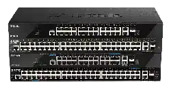
The DGS-1520-28MP and DGS-1520-52MP switches support Power over Ethernet (PoE) as defined by the IEEE
802.3af and 802.3at. All ports can support PoE up to 30W. The Switch ports can supply about 48 VDC power to
Powered Devices (PDs) over Category 5 or Category 3 UTP Ethernet cables. The Switch follows the standard Power
Sourcing Equipment (PSE) pin-out Alternative A, whereby power is sent out over pins 1, 2, 3, and 6. The Switches
work with all D-Link 802.3af capable devices.
The Switch includes the following PoE features:
• Auto-discovery recognizes the connection of a PD and automatically sends power to it.
• The auto-disable feature occurs under two conditions:
o If the total power consumption exceeds the system power limit
o If the per-port power consumption exceeds the per port power limit
• Active circuit protection automatically disables the port if there is a short. Other ports will remain active.
Based on IEEE 802.3af/at, power is received and supplied according to the following classifications:
Class Maximum power used by the PD Maximum power supplied by the Switch
0
12.95 Watts 15.4 Watts
1
3.84 Watts 4 Watts
2
6.49 Watts 7 Watts
3
12.95 Watts 15.4 Watts
4
25.5 Watts 30 Watts
Loading ...
Loading ...
Loading ...
