Loading ...
Loading ...
Loading ...
DGS-1520 Series Gigabit Ethernet Smart Managed Switch Web UI Reference Guide
100
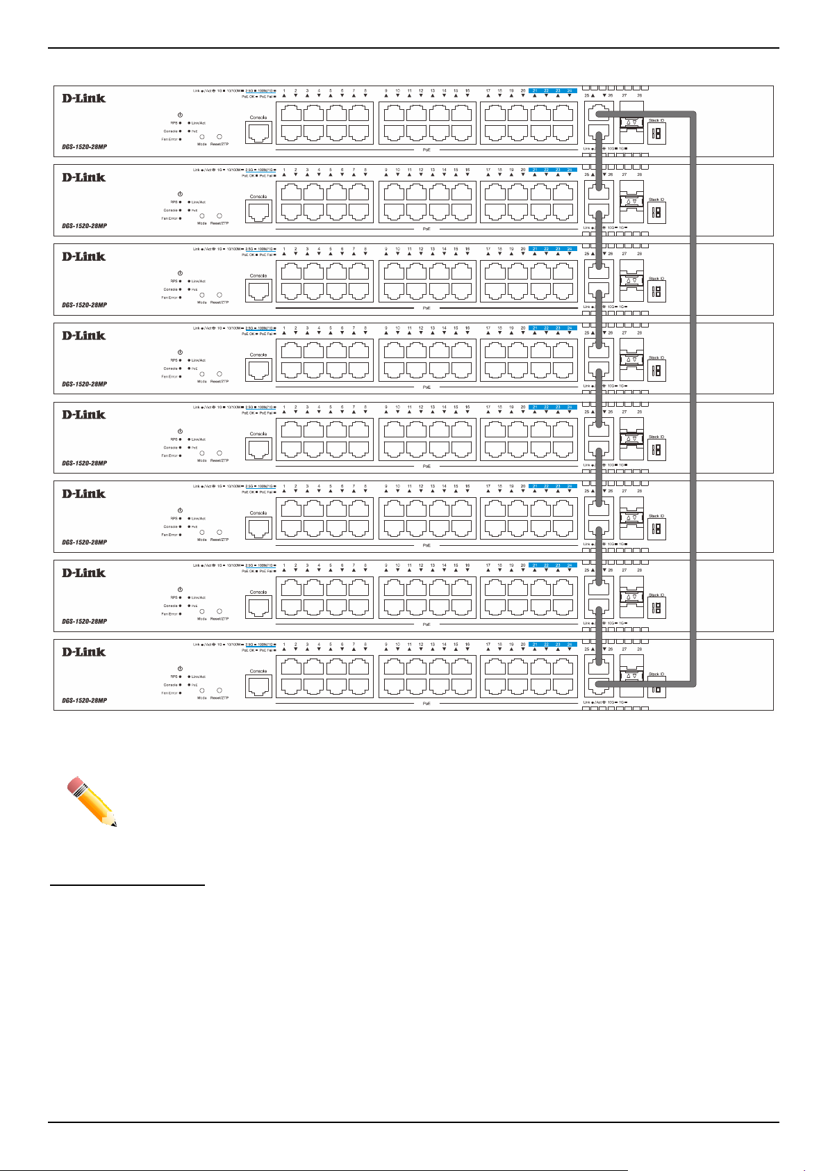
In the following diagram, switches are stacked in the Duplex Ring topology using the two 10GBASE-T ports.
Figure 4-85 Duplex Ring Stacking Topology
NOTE: Stacking Input/Output logical port 1 (SIO1) and SIO2 are logical stacking port pairs. A logical
stacking port pair must always be connected to the same Switch in the stack. Splitting logical
stacking port pairs between different Switches in the stack might not guarantee a stable
stacking connection. See Stacking Bandwidth on page 103 for more information.
Switch Roles in a Stack
Within each of these topologies, each Switch plays a role in the Switch stack. These roles can be set by the user per
individual Switch, or if desired, can be automatically determined by the Switch stack.
Three possible roles exist when stacking with the Switch.
• Primary Master - The Primary Master is the leader of the stack. It will maintain normal operations, monitor
operations and the running topology of the Stack. This Switch will also assign Stack Unit IDs, synchronize
configurations, and transmit commands to remaining Switches in the Switch stack. The Primary Master can be
manually set by assigning this Switch the highest priority (a lower number denotes a higher priority) before
physically assembling the stack, or it can be determined automatically by the stack through an election process.
This determines the lowest MAC address and then will assign that Switch as the Primary Master if all priorities
are the same. The Primary master is physically displayed by the seven segment LED to the far right on the front
panel of the Switch where the LED will flash between its given Box ID and 'H'.
Loading ...
Loading ...
Loading ...