Loading ...
Loading ...
Loading ...
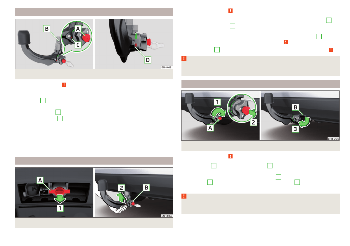
Check the setting of the standby position
Fig. 220 Ready position
Read and observe on page 183 first.
Correctly adjusted standby position » Fig. 220
The key
A
is in the unlocked position - the arrow on the key points to the
symbol
.
The locking ball
B
can be pushed fully into the tow bar.
The red marking
C
on the hand wheel points to the white marking on the
ball bar.
There is a clear gap of approx. 4 mm
D
between the hand wheel and the
tow bar.
When in the ready position, the key cannot be removed from the lock. The ball
bar is thus set ready for installation.
Assembling the tow bar – Step 1
Fig. 221
Remove cap for receiving shaft / use ball bar
Read and observe on page 183 first.
›
To prepare for the installation, remove the cap for the receiving shaft
A
in
the direction of arrow
1
» Fig. 221.
›
To install, hold the ball rod from underneath » Fig. 221.
›
Push the ball rod into the receiving shaft in the direction of arrow
2
until it
stops. The ball rod must audibly snap into place » .
The hand wheel
B
rotates back automatically and rests on the ball rod » .
WARNING
Do not hold the hand wheel with your hand when attaching the ball bar -
there is a risk of finger injury.
Assembling the tow bar – Step 2
Fig. 222
Secure the lock and remove key / place cap on lock
Read and observe on page 183 first.
›
Turn the key
A
in the direction of arrow
1
, so that the arrow on the key
symbol » Fig. 222 shows.
›
Remove the key in the direction of the arrow
2
.
›
Fit the cap
B
on the lock in the direction of the arrow
3
.
›
Check that the ball rod is securely attached » page 186.
WARNING
After fitting the tow bar, always secure the lock and remove the key. The
tow bar must not be operated with the key inserted.
185
Towing device and trailer
Loading ...
Loading ...
Loading ...